Embed Size (px)
DESCRIPTION
1. Mine Subsidence- Prediction and Reduction2. Mineral Conservation and Development Rules, 19883. Mines and Minerals (Development and Regulation) Act, 1957
Citation preview

ENVIRONMENTAL MANAGEMENTAssignment IV
National Institute of Technology, Rourkela
DEPARTMENT OF MINING ENGINEERING
Ashish Kumar
Roll Number: - 110MN0496
Mine Subsidence- Prediction and Reduction
INTRODUCTION
Subsidence is an inevitable consequence of underground mining—it may be small and localized or extend over large areas, it may be immediate or delayed for many years. During recent years, with the expansion of urbanization and increased concern for the environment, it is no longer possible to ignore its aftermath. In the United States, mining companies have, therefore, begun to devote attention to the subject and study it in a methodical manner. Appropriate regulations have also been promulgated by various government agencies, depending on the needs of the region, in order to protect the public interest.
The problems associated with subsidence have been recognized since the inception of mining and mentioned in the literature as far back as Agricola’s De Re Metallica in 1556. The initial “vertical theory” was modified by the researches of Coulomb, Toillez, Gonot, Rziha, and Fayol (Peele, 1952). Significant contributions may also be credited to Rucloux, Durmond, Callon, Goupilliere, Schulz, von Sparre, von Dechen, Hausse, and Jicinsky (Peele 1952). In the early part of the century, Briggs (1929) presented his comprehensive treatise on the subject. In the United States, the early investigations of Richardson (1907), Young and Stoek (1916), Rice (1923), Rutledge (1923), Crane
(1925, 1929, 1931), and Allen (1934) are notable. The motivation behind these studies was the severe damage caused to structures, communications, and agricultural lands; the victims (mostly property owners) demanded compensation and restitution from the mine operators, and frequently resorted to court action. In order to defend against unjustified claims, measurements of ground movements were made. These data, along with theoretical concepts on the development of these movements, gradually evolved into the subject of mine subsidence engineering. Courses specifically devoted to the subject have been taught in German academies since 1931 and in US universities only since 1963.
The major objectives of subsidence engineering are
1. Prediction of ground movements.
2. Determining the effects of such movements on structures and renewable resources.
3. Minimizing damage due to subsidence.
Thus it is evident that subsidence engineering not only entails the study of ground movements, structural geology, and Geomechanics (both soil and rock mechanics), but also encompasses a knowledge of surveying, mining and property law, mining methods and techniques, construction procedures, communications technology, agricultural science, hydrology and hydrogeology, urban planning, and socioeconomic considerations.
Although the mining of all underground minerals may result in subsidence, most studies to date have concentrated on the extraction of flat bedded deposits—primarily coal. Hence throughout this discussion, reference to coal mining is made frequently. The information presented herein is, therefore, most pertinent to coal mining, although it generally applies to other bedded deposits. The principles may be also extrapolated to other mining methods, but the conclusions need validation by actual experience.
The pumping of geofluids, such as petroleum, natural gas, geothermal brines, and water, constitute “mining” in the strict sense and also cause subsidence. The effects of fluid withdrawal have been investigated at some length, although they are beyond the scope of this chapter. But the lowering of the water table in the region adjoining mining activity also induces ground movements, thereby causing surface damage, which must not be overlooked.
PRINCIPLES OF SUBSIDENCE
Development of Subsidence
Whenever a cavity is created underground, due to the mining of minerals or for any other reason, the stress field in the surrounding strata is disturbed. These stress changes produce deformations and displacements of the strata, the extent of which depends on the magnitude of the stresses and the cavity dimensions (Chapter 10.2). With time, supporting structures deteriorate and the cavity enlarges, resulting in instability. This induces the superjacent strata to move into the void. Gradually, these movements work up to the surface, manifesting themselves as a depression. This is commonly referred to as subsidence. Thus mine subsidence may be defined as ground movements that occur due to the collapse of the overlying strata into mine voids. Surface subsidence generally entails both vertical and lateral movements.
Surface subsidence manifests itself in three major ways:
1. Cracks, fissures, or step fractures.
2. Pits or sinkholes.
3. Troughs or sags.
Surface fractures may be in the form of open cracks, stepped slips, or cave-in pits and reflect tension or shear stresses in the ground surface.
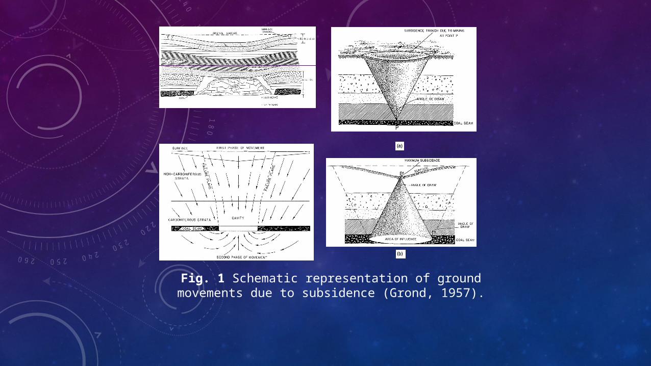
Fig. 1 Schematic representation of ground movements due to subsidence (Grond, 1957).
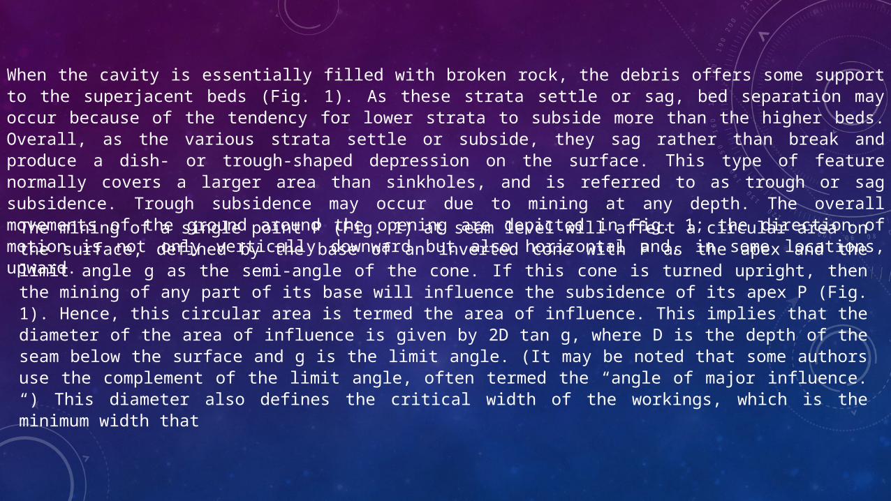
When the cavity is essentially filled with broken rock, the debris offers some support to the superjacent beds (Fig. 1). As these strata settle or sag, bed separation may occur because of the tendency for lower strata to subside more than the higher beds. Overall, as the various strata settle or subside, they sag rather than break and produce a dish- or trough-shaped depression on the surface. This type of feature normally covers a larger area than sinkholes, and is referred to as trough or sag subsidence. Trough subsidence may occur due to mining at any depth. The overall movements of the ground around the opening are depicted in Fig. 1; the direction of motion is not only vertically downward but also horizontal and, in some locations, upward.
The mining of a single point P (Fig. 1) at seam level will affect a circular area on the surface, defined by the base of an inverted cone with P as the apex and the limit angle g as the semi-angle of the cone. If this cone is turned upright, then the mining of any part of its base will influence the subsidence of its apex P (Fig. 1). Hence, this circular area is termed the area of influence. This implies that the diameter of the area of influence is given by 2D tan g, where D is the depth of the seam below the surface and g is the limit angle. (It may be noted that some authors use the complement of the limit angle, often termed the “angle of major influence. “) This diameter also defines the critical width of the workings, which is the minimum width that
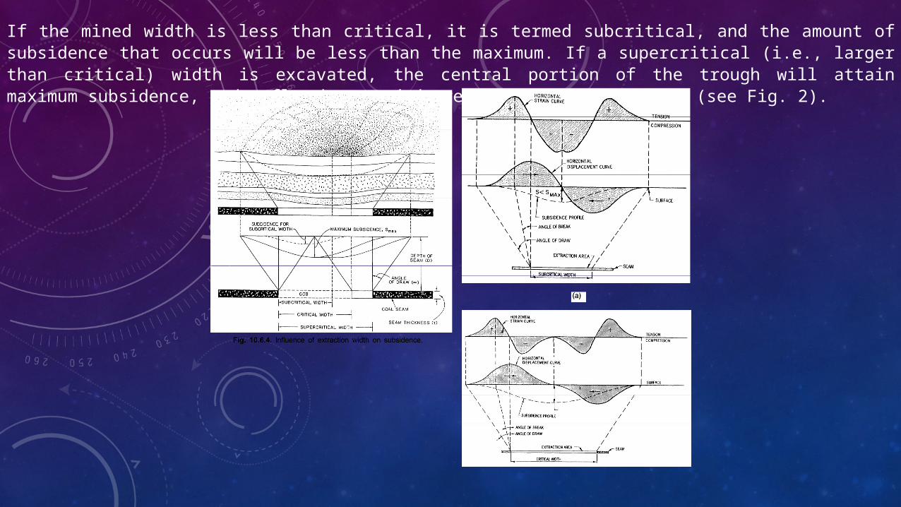
If the mined width is less than critical, it is termed subcritical, and the amount of subsidence that occurs will be less than the maximum. If a supercritical (i.e., larger than critical) width is excavated, the central portion of the trough will attain maximum subsidence, and a flat-bottomed depression will be produced (see Fig. 2).

Components of Subsidence
Subsidence consists of five major components, which influence damage to surface structures and renewable resources (see Fig. 10.6.7):
1. Vertical displacement (settlement, sinking, or lowering).
2. Horizontal displacement (lateral movement).
3. Slope (or tilt), i.e., the derivative of the vertical displacement with respect to the horizontal.
4. Horizontal strain, i.e., the derivative of the horizontal displacement, with respect to the horizontal.
5. Vertical curvature (or flexure), which may be approximated by the derivative of the slope, or the second derivative of the vertical displacement with respect to the horizontal.
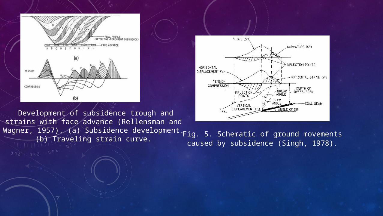
Development of subsidence trough and strains with face advance (Rellensman and Wagner, 1957). (a) Subsidence
development. (b) Traveling strain curve. Fig. 5. Schematic of ground movements caused by subsidence (Singh, 1978).
Factors Affecting Mine SubsidenceSeveral geologic and mining parameters and the nature of the structure affect the magnitude and extent of subsidence that occur due to coal mining (Henry, 1956; King and Whetton,
1. Effective Seam Thickness: The thicker the seam extracted, the larger the amount of surface subsidence that is possible. In some cases, the entire seam may not be mined or some pillars or other nonminable coal may be left in place. Hence the effective seam thickness should be considered. In thick beds, the slenderness (height-to-width ratio) of the pillars is higher for a given extraction ratio. Slender pillars are normally more prone to failure.
2. Multiple Seams: Where multiple worked-out mining horizons exist, collapse could be initiated from any one of several levels, thereby increasing the likelihood of subsidence events, because the adjacent strata are disturbed. This is especially true when the prior mining was in an overlying seam.
3. Seam Depth: A school of thought exists that at greater depths, an arch is formed over the mine cavity, preventing surface subsidence. In recent years, this has been gradually refuted. Perhaps the time period that elapses before subsidence effects are observed at the surface is prolonged, but the total amount of subsidence does not appear to be changed; that is, subsidence is independent of depth (Orchard, 1964). Pit depths generally do not exceed certain limits, as discussed previously (see 10.6.2.1).
4. Dip of Seam: When the coal seam being mined is inclined, an asymmetric subsidence trough is formed that is skewed toward the rise; that is, the limit angle is greater on the dip side of the workings. The strains are also smaller toward the dip direction. Pillars in steeply dipping seams tend to be less stable.
5. Competence of Mine Roof and Floor: Since subsidence propagates from the mine level, the characteristics of the mine roof and floor are vital in the initiation of subsidence movements. Soft fireclay floors, especially if susceptible to further weakening due to moisture, induce pillar punching or heave. Weak roofs, composed of shales, siltstones, and limestones, permit falls that are accentuated if punching also occurs. Competent roof beds tend to support the overlying strata longer and hence delay the subsidence. Also, when these fracture, they occupy a greater bulk volume than weaker strata (which compact more). When both the roof and floor are strong, the pillars tend to spall and crush.
6.Nature of Overburden: Strong massive beds above the mine level tend to prop the overburden for a prolonged period and defer the occurrence of subsidence.
7. Near-surface Geology: The soils and unconsolidated rocks near the surface tend to accentuate subsidence effects. The geologic materials are less homogeneous and isotropic than the underlying strata, and often behave in an inconsistent manner. Cracks and fissures may initially form in a 50-ft (15-m) thick layer from the surface (Singh and Kendorski, 1981). Later, these may be filled by plastic deformation or material transportation by water. Occasionally, however, water flow may accentuate these fissures and form gullies. Structures and renewable resource lands are thereby adversely affected.
8. Geologic Discontinuities: The existence of faults, folds, and the like may increase subsidence potential. Mining disturbs the equilibrium of forces in the strata and may trigger movement along a fault plane, due to ease of slippage, causing either settlement or upthrust at the surface, which may appear as a series of step fractures. The effects of the other parameters may need to be discounted in areas of adverse geological conditions.
9. Fractures and Lineaments: Natural fractures and lineaments affect surface subsidence, but a strong correlation has not been established to date.
10. In Situ Stresses: High horizontal stresses tend to restrain surface subsidence by forming a ground arch in the immediate mine roof (Lee and Abel, 1983). The arch height and stability are sensitive to the ratio of vertical to horizontal stresses. Highly stressed arches may fail violently (e.g., the Urad molybdenum mine, Colorado). Roof instability and floor heave, resulting from high horizontal stresses and their orientation, need to be taken into account when laying out coal mines in the Allegheny Plateau (Aggson, 1978).
11. Degree of Extraction: Lower extraction ratios tend to delay subsidence. It is less prevalent in areas superjacent to first mining, since sufficient pillar support is generally available without crushing of pillars. In second mining, the cross section of the pillars is reduced by splitting and slicing. Localized stress buildups promote crushing, and excessively wide roof areas exposed between pillars stimulate roof failure. Third mining is almost invariably followed by roof collapse in the workings. Surface manifestations are a function of time, dependent on the rate of upward propagation of settlement.
12. Surface Topography: As may be anticipated, sloping ground tends to emphasize downward movements because of gravity. Tensile strains may become more marked on hilltops and decrease in valleys. Surface effects are influenced accordingly.
13. Groundwater: Deformation of the strata around mined areas may alter drainage gradients, resulting in the formation of surface or underground reservoirs (in aquifers). Low-lying areas, such as in central Illinois, may become flooded. Rocks may be weakened by saturation. Erosion patterns could change, and in limestone areas, caverns or karst areas may be created over a period of time.
14. Water Level Elevation and Fluctuations: Water reduces the strength and stiffness of pillars and the roof and floor markedly. Periodic changes in mine humidity promote deterioration of all these members. Floor softening permits punching, resulting in instability and subsidence. Flow through fissures cause seepage pressures, endangering the stability of the rock mass. Cleavage and bedding planes are lubricated by water, inducing movements.
15. Mined Area: The critical width needs to be exceeded along both the lateral and longitudinal axes to achieve maximum subsidence. This is especially important if competent strata present in the overburden tend to bridge across the panel and decrease subsidence when the panel width is less than the critical width, even though the length of the panel is greater.
16. Method of Working: The type of initial subsidence experienced, namely pit or trough, depends on whether room and pillar or longwall mining is being practiced. With room and pillar mining, the eventual collapse of pillars may lead to trenching or sagging of the surface. The displacements and strains over short distances, when they start appearing on the surface, are significant. Nearly immediate but predictable subsidence occurs with longwall mining. Harmonic mining, either by working adjacent longwalls in the same seam or superposed panels in different seams, can be effectively utilized to neutralize compressive and tensile strains and thereby protect surface structures. However, the method is not readily applied and is restricted for use only where mining costs become subservient to historical or social demands.
17. Rate of Face Advance: Surface subsidence follows the face as it progresses in the panel. If the coal extraction rate varies markedly, the traveling strains also fluctuate. This results in large differential settlements. A fairly rapid, even rate of face advance is best (Legget, 1972).

Measurement of Subsidence
In order to make subsidence measurements, it is essential to erect monuments that will undergo the same vertical or horizontal displacements as the ground. Several designs of monuments have been used, some of which are depicted in Fig. 10.6.8. Whichever design is selected for use, it should be stable and firmly anchored about 5 ft (1.5 m) below the ground surface so as not to be affected by frost or other surface effects.
The choice of measuring instruments that may be used for subsidence measurements depends on a number of parameters (Panek, 1970):
1. Objectives of the investigation.
2. Area to be covered.
3. Topography of the region.
4. Profiles along which monuments are installed.
5. Spacing and number of monuments or observation stations.
6. Total cost that can be tolerated.
7. Duration of the investigation; survey frequency.
Labor requirements for surveying and data reduction

The horizontal distance between monuments depends on the subsidence gradient. Generally, however, a compromise has to be reached between placing the monuments too close, which increases installation and measurement cost, and too far apart, which does not give enough readings to depict the measured variables adequately. The British National Coal Board (NCB) (Anon., 1975a) has recommended a monument spacing of 0.05D, where D is the depth of the mined bed. In the United States, the tendency is to increase this distance (Deere, 1961; Gentry and Abel, 1978), and spacings of 0.05D to 0.1D have been advocated (Panek, 1970). The accuracy of the measurements should be such as to detect strains of 10–4, which is about 1/10th the strain-level for structural damage. The method of measurement and the precautions necessary depends on the distance between monuments and may be obtained from any text on surveying (see also Chapter 8.2; Panek, 1970; O’Rourke et al., 1977).
Vertical displacements may be measured by trigonometric leveling (precision optical or laser), differential leveling, or tilt measurement. When using the theodolite, vertical angles must be measured correct to ½ second of arc. With precise leveling, a micrometer direct reading to about 0.005 ft (1.5 mm) should be employed. An inclinometer with a sensitivity of 10 seconds of arc is generally adequate for subsidence measurements. Secondorder subsidence surveys with geodetic level and invar scale or equivalent, should close within 0.035(M)1/2 feet, where M is the circuit length in miles (Moffitt and Bouchard, 1975), an accuracy of 0.01 ft (3.3 mm) over a 1000-ft (305-m) line. In mountainous or swampy areas, third-order control with a closure of 0.052(M) 1 / 2 ft may be used, an accuracy of 0.02 ft (6.5 mm) in 1000 ft (328 m). Tiltmeters for use in long-term (several years) subsidence surveys have been developed (e.g., Jacobsen et al., 1975; Holzhausen, 1986).

Promising empirical methods for prediction of subsidence over underground mines consist of the following:
1. Graphical.
2. Profile functions.
3. Influence functions.
Graphical Method: This simply involves displaying subsidence data in the form of graphical charts or nomographs, whereby subsidence magnitude and the associated parameters may be directly obtained for a specified set of mine parameters. This method is adaptable in areas where considerable subsidence data exist, and its applicability is generally restricted to relatively few, geologically similar regions. This technique has seen considerable use in the United Kingdom (Anon., 1975a).
Profile Functions: This involves the derivation of a mathematical function that can be used to plot a complete profile of the subsidence trough at the surface. It differs from a phenomenological approach in that the constraints employed in the profile function are empirically derived from observed data. This method can be readily applied to geologically dissimilar conditions by modifying the constant values. Profile functions have been successfully applied in several countries abroad such as Poland, Hungary, the Soviet Union, and currently in the United States
Influence Functions: This principle for subsidence prediction is based on the extraction of infinitesimal elements of area. Subsidence at any point on the surface is obtained from the sum of the influence of each extracted element, using the principle of superposition. Unlike profile functions, influence functions cannot be found directly by measurement. In addition, this method assumes a homogeneous, isotropic overburden material and, therefore, has limited accuracy. In general, influence functions have been found to be especially suitable for subsidence prediction over underground workings with irregular or complex geometries. This method has received considerable attention in Europe, and to a limited extent in this country (Sinclair, 1963; Gill, 1971; Brauner, 1973; Adamek and Jeran, 1981; Hood et al., 1981; Karmis et al., 1981; Peng et al., 1986). Table 10.6.2 depicts a few influence functions.
Phenomenological Methods: These are primarily based on the principles of continuum mechanics and assume the media to be elastic (Salamon 1963–4; Berry, 1969; Plewman et al., 1969; Crouch, 1973), viscoelastic (Marshall and Berry, 1967), plastic
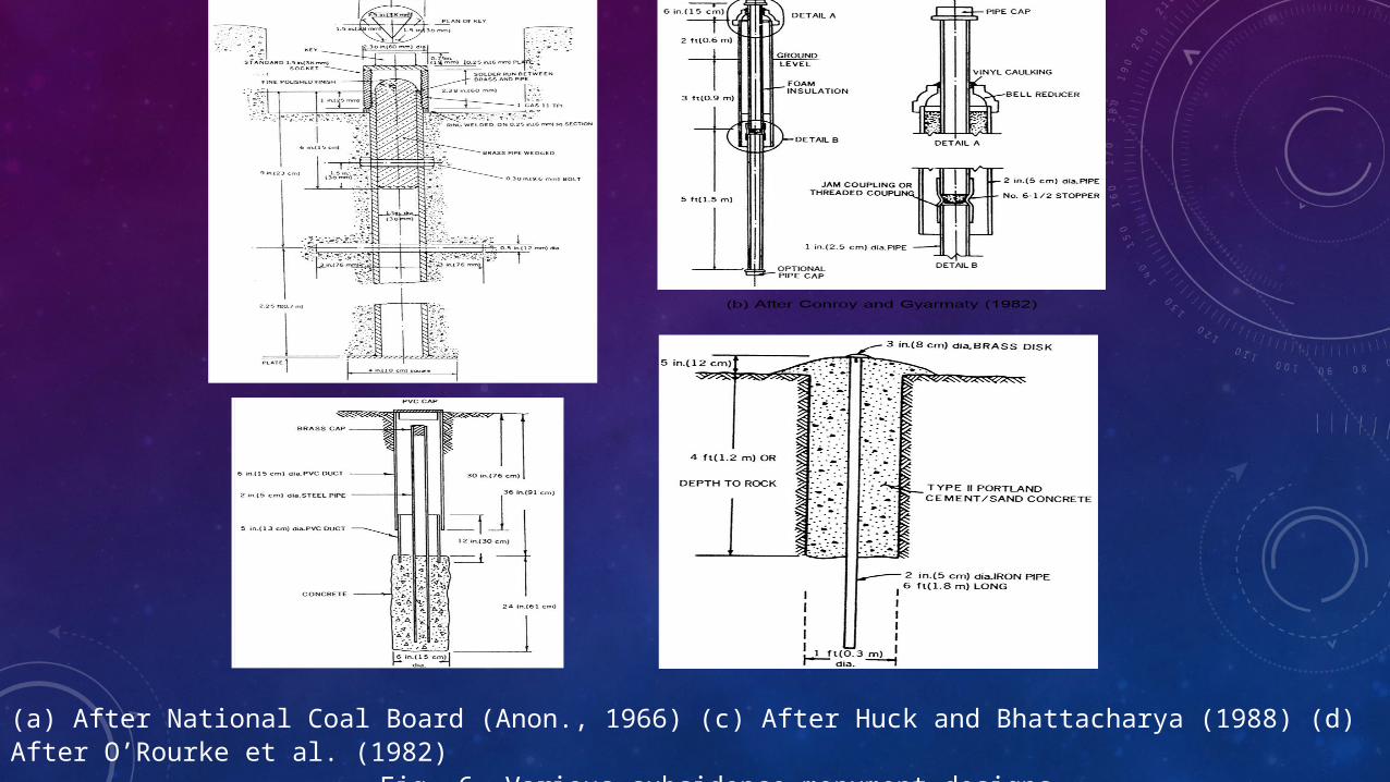
(a) After National Coal Board (Anon., 1966) (c) After Huck and Bhattacharya (1988) (d) After O’Rourke et al. (1982)Fig. 6. Various subsidence monument designs.

Table 1 Profile Functions
Time Effects
The duration of subsidence resulting from mining is composed of two distinct phases: (1) active and (2) residual. Active subsidence refers to all movements occurring simultaneously with the mining operations, while residual subsidence is that part of the surface deformation that occurs following the cessation of mining (or in the case of longwall mining, after an underground excavation has reached its critical width). The duration of residual subsidence is of particular importance from the standpoint of structural damage at the surface as well as from a legal perspective.
The latter involves evaluating the extent of liability of underground mine operators for post mining subsidence. Time spans during which surface subsidence may occur vary markedly with the mining method being used. Longwalls induce subsidence rapidly, beginning almost immediately after mining. With room and pillar systems, major occurrences of surface subsidence may be delayed for decades until the support pillars have substantially deteriorated and collapsed. The actual time involved depends on a number of factors such as the strengths of coal, roof, and floor; extent of fracturing; presence of water; depth of workings; pillar size; and percentage extraction. Hence prediction of when or how much damage may occur becomes difficult.
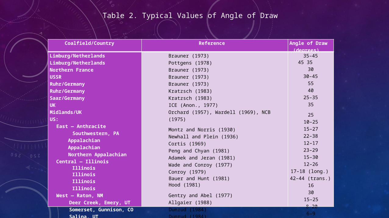
Table 2. Typical Values of Angle of Draw
Coalfield/Country Reference Angle of Draw (degrees)
Limburg/NetherlandsLimburg/NetherlandsNorthern FranceUSSRRuhr/GermanyRuhr/GermanySaar/GermanyUKMidlands/UKUS:
East — AnthraciteSouthwestern, PA
AppalachianAppalachianNorthern Appalachian
Central — IllinoisIllinois IllinoisIllinoisIllinois
West — Raton, NMDeer Creek, Emery, UTSomerset, Gunnison, COSalina, UT
Sheridan, WY
Brauner (1973)Pottgens (1978)Brauner (1973)Brauner (1973)Brauner (1973)Kratzsch (1983)Kratzsch (1983)ICE (Anon., 1977)Orchard (1957), Wardell (1969), NCB (1975)
Montz and Norris (1930)Newhall and Plein (1936)Cortis (1969)Peng and Chyan (1981)Adamek and Jeran (1981)Wade and Conroy (1977)Conroy (1979)Bauer and Hunt (1981) Hood (1981)
Gentry and Abel (1977)Allgaier (1988)Dunrud (1984)Dunrud (1984)Dunrud (1984)
35–4545 35
3030–455540
25–3535
2510–2515–2722–3812–1723–2915–3012–26
17–18 (long.)42–44 (trans.)
1630
15–258–206–9
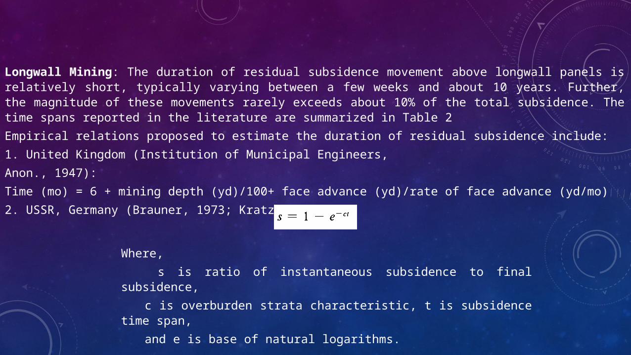
Longwall Mining: The duration of residual subsidence movement above longwall panels is relatively short, typically varying between a few weeks and about 10 years. Further, the magnitude of these movements rarely exceeds about 10% of the total subsidence. The time spans reported in the literature are summarized in Table 2
Empirical relations proposed to estimate the duration of residual subsidence include:
1. United Kingdom (Institution of Municipal Engineers,
Anon., 1947):
Time (mo) = 6 + mining depth (yd)/100+ face advance (yd)/rate of face advance (yd/mo)
2. USSR, Germany (Brauner, 1973; Kratzsch, 1983):
Where,
s is ratio of instantaneous subsidence to final subsidence,
c is overburden strata characteristic, t is subsidence time span,
and e is base of natural logarithms.
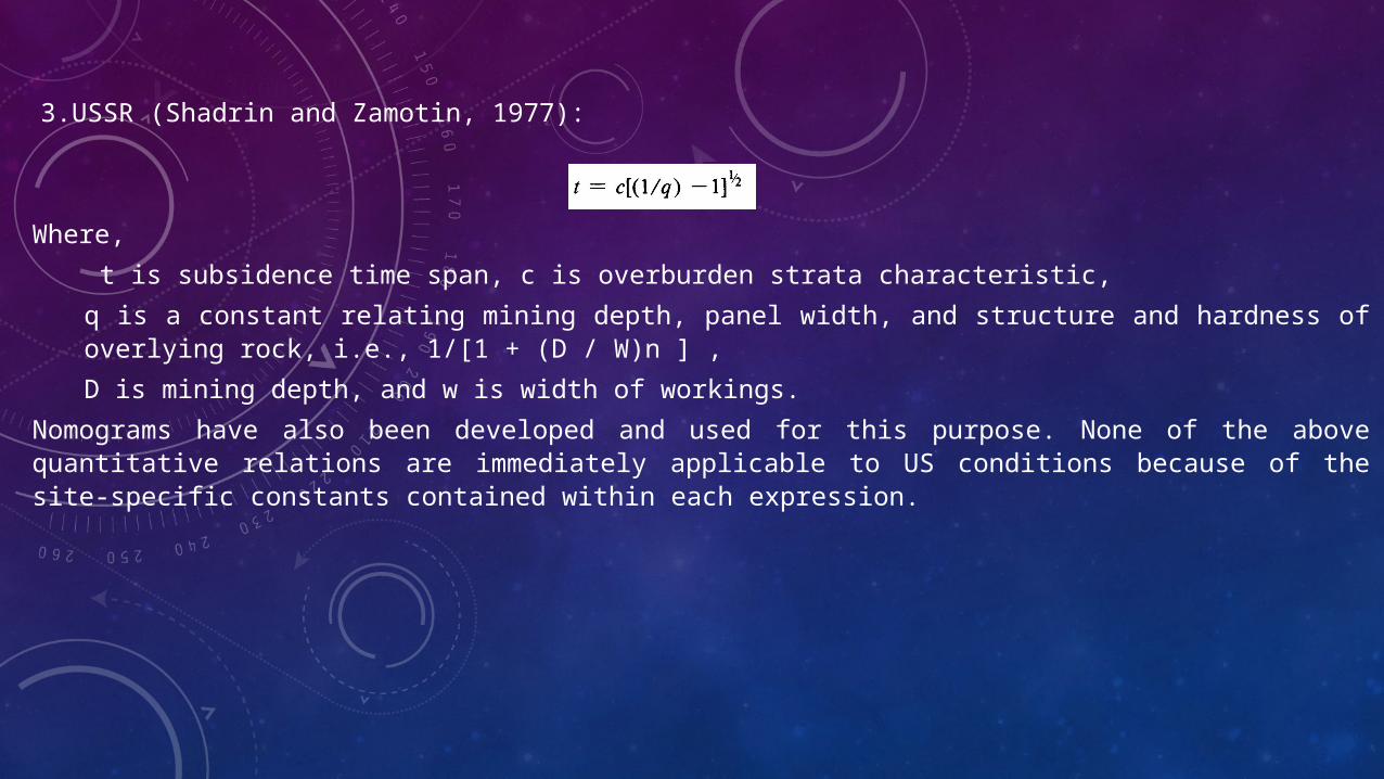
3.USSR (Shadrin and Zamotin, 1977):
Where,
t is subsidence time span, c is overburden strata characteristic,
q is a constant relating mining depth, panel width, and structure and hardness of overlying rock, i.e., 1/[1 + (D / W)n ] ,
D is mining depth, and w is width of workings.
Nomograms have also been developed and used for this purpose. None of the above quantitative relations are immediately applicable to US conditions because of the site-specific constants contained within each expression.

Room and Pillar Mining: Mechanism of Subsidence Development—In room and pillar mining without pillar recovery, the magnitude of active subsidence is generally small, and the ground surface may experience a variable frequency of subsidence incidents during this period. The coal pillars and the surrounding rock are usually relatively sound at this time with only minor deflections of the roof being transmitted to the surface.
Sometime after mining, however, complete collapse of the abandoned pillars and the adjacent strata may occur as a result of natural causes or human activities. These processes are likely to continue until all the voids created by mining excavation have been filled by the caved strata. Consequently, in the case of room and pillar mining, the residual subsidence can be the major subsidence measured on the surface.
There have been some misconceptions among the US mining community that surface subsidence may be avoided if certain conditions are fulfilled:
1. Sufficient coal is left unworked to serve as load-bearing pillars (generally over 50%).
2. Mining is conducted at great depths.
3. Strata overlying the workings contain competent beds.
Recent studies, however, have shown that no matter how well-designed a room and pillar layout might be, the additional weight transmitted to the pillars due to excavations will cause measurable deformation on the pillars, and these movements will eventually be transmitted to the surface. Depending upon the extent of pillar loading and the characteristics of the pillars and the superincumbent material, the surface deflection may vary from considerable to negligible, and sometimes is nearly undetectable. The long-term stability of mine pillars is extremely difficult to determine.
The three basic mechanisms responsible for residual subsidence over room and pillar mines include:
1. Collapse of roof beds spanning adjacent pillars.
2. Pillar failures.
3. Squeezes or crushes.
1. Roof Collapse. Over remnant pillars, this is perhaps the most prevalent failure mechanism associated with abandoned room and pillar mines. Depending on certain geometric and geotechnical factors, the caving process may be arrested at some point in the overburden or it may extend upwards to the surface. The surface expression of this process is generally in the form of a localized depression or pit.
The height to which the collapse process can take place is a function of
a. Volume of the original mine opening or room.
b. Bulking factor of the strata material.
c. Location and thickness of overlying competent strata.
Two basic modes of roof failure have been recognized, namely, shear and flexural failure (Morgan, 1973). The former usually initiates diagonal tension cracks near the junction of the mine pillar and the roof, and the latter causes tension cracks near the midspan of the roof. Both result in voids above the mine level. Dependent on the mechanism of failure of the individual roof beds and their tensile and shear strengths, a variety of geometric forms of collapse are possible, ranging from conical through wedge to rectangular. For a given width of mine opening, it can be demonstrated that, for each type of collapse, the height of collapse is a function of the overlying strata. The influence of competent strata in the overburden has been neglected in this analysis (Piggott and Eynon, 1977).
2. Pillar Failures. These occur due to changes in the environment or surcharged loading and may take place at the time of mining or after considerable delay. They result in trough-like subsidence.
In general, subject to pillar geometry, pillar failure does not ordinarily occur at shallow depths since the size of coal pillars left behind are usually much greater than that required to support the overlying strata or any additional loading from surface development. However, where very small pillars or “stubs” exist within a given mining section, these may fail and cause sufficient loads to be transferred to adjoining pillars by arching, resulting in extended failure.
In most instances, pillar failures coincide with some phase of mining, such as pillar robbing on the retreat, abandonment of a particular mining area, or working other seams in close proximity. Another common cause of pillar failure is the action of concentrated foundation loads, from pile foundations or otherwise, being transmitted onto the remnant pillars (Piggot and Eynon, 1977).
3. Squeezes or Crushes. When abandoned pillars punch into either the immediate roof or floor that might have been weakened or altered by the action of water or other weathering processes, squeezes (crushes) may result. Generally, the surface settles as a trough or basin.
The mechanism of failure in this case is not unlike the failure of building foundations as the load carried by the mine pillar is transferred to the floor (or roof). If the bearing capacity of either the roof or floor is exceeded, squeezing may occur. The following factors (Gray et al., 1977) favor bearing capacity failure:
a. Underclay mine floor.
b. High pillar stresses.
c. Flooded mine conditions.
Factors Influencing Duration of Residual Subsidence—The factors in room and pillar mines that govern the duration of residual subsidence have not been quantified as yet. Probably the following parameters play a role:
4. Depth of Working: Increased depth implies a longer duration for subsidence movements. Any instability caused at the mine level has to propagate through the overburden in order to reach the surface.
2. Mine Geometry: This may be expressed in terms of the following attributes:
a. Seam thickness.
b. Pillar width-to-height ratio.
c. Extraction ratio.
d. Presence of multiple panels.
e. Presence of multilevel workings.
Increased seam thickness increases the potential for instability of pillars and speeds up the subsidence process.
Both the pillar width-to-height ratio and extraction ratio reflect upon the safety factor built into the mine design. Pillar width-to-height ratios greater than 0.1 and extraction ratios of less than 50% have both been claimed to permit no surface subsidence. Although mines designed to these standards have been known to be stable for long periods of time, sometimes more than a hundred years, this is not strictly true.
Presence of multiple panels and multilevel workings generally result in a shorter residual subsidence phase since they increase the volume of underground voids.
5. Strength and Deformation Characteristics of the Roof Floor, and Pillar: Over the long term, these affect the duration of surface subsidence depending on the interrelationships of these structural members.
6. Types of Roof Control: Roof control practices in a mine influence the relative susceptibility of the roadways to collapse; for example, bolted mines tend to subside faster than those with cribs, steel supports, or other types of bracing.
7. Character of the Overburden: Significant aspects which profoundly govern the duration of subsidence movements are
a. Thickness of surficial soil beds.
b. Lithology.
c. Structural geology.
Soil thickness is important since the fractures propagate through it rapidly. Also granular materials (e.g., sands) offer less bridging capacity than fine-grained soils (i.e., clays).
8. Presence of Old Mined-out Workings: Old workings in the vicinity of an active mine accelerate the rate of residual subsidence, since the surrounding strata are disturbed.
9. In Situ Stress Field: The existence of high horizontal stresses impacts the time for subsidence since the structural integrity of the mine supports is affected.
10. Water: The presence of water reduces the strength and stiffness of mine pillars, roof, and floor in flooded mines. Further, softening of the floor (e.g., underclay) encourages pillar punching, resulting in instability and subsidence. Flow of water through fissures causes seepage pressures in the rocks, endangering the rock mass stability. Generally, the formation of pits in shallow mines is promoted by these factors. Dewatering of flooded mines accelerates coal pillar deterioration by exposing submerged pillars to the damaging effects of air and removing the buoyant support afforded by the water.
11. Nonmining factors: Those that affect subsidence include
a. Mine fires.
b. Earthquakes.
c. Tectonic movements.
d. Surface precipitation.
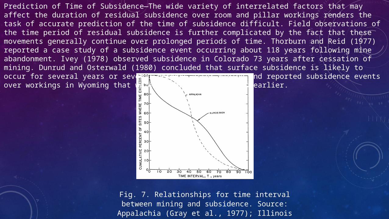
Fig. 7. Relationships for time interval between mining and subsidence. Source: Appalachia (Gray et al., 1977); Illinois data
(Bauer and Hunt, 1981)
Prediction of Time of Subsidence—The wide variety of interrelated factors that may affect the duration of residual subsidence over room and pillar workings renders the task of accurate prediction of the time of subsidence difficult. Field observations of the time period of residual subsidence is further complicated by the fact that these movements generally continue over prolonged periods of time. Thorburn and Reid (1977) reported a case study of a subsidence event occurring about 118 years following mine abandonment. Ivey (1978) observed subsidence in Colorado 73 years after cessation of mining. Dunrud and Osterwald (1980) concluded that surface subsidence is likely to occur for several years or several decades after mining and reported subsidence events over workings in Wyoming that were driven 25 to 80 years earlier.

Table 3. Residual Subsidence Duration over Longwall Mines
Reference Coalfield
Country/
Residual Subsidence Duration
Institution of Municipal Engineers (Anon.,1947)Orchard & Allen (1974) Collins (1977)Grard (1969)Brauner (1973)
Brauner (1973)
Shadrin and Zamotin (1977)Gray et al. (1977)
Hood et al. (1981)
UK UKUKFranceGermany
USSR
USSR
US/Appalachian
US/Illinois
2 to 10 years
Several months to 3 to6 years (strong overburden)2 to 4.5 years6 to 12 months1. year (Cretaceousoverburden)
2 years (sandstone overburden)
2. years (shallowmines)4 to 5 years (deep mines, > 1300 ft or 400m)2 to 25 months
Few months to few years12 months
CONTROL AND PREVENTION OF DAMAGE
There are four types of measures that may be adopted to control subsidence damage (Singh, 1985):
1. Alteration in mining techniques.
2. Postmining stabilization.
3. Architectural and structural design.
4. Comprehensive planning.
Each of these encompasses several methods.
Alteration in Mining Techniques
Partial Mining: This may be accomplished in a number of ways:
1. Leaving protective zones, which is the most commonly used procedure (Fig. 10.6.15). The zone may entail:
a. Leaving the entire pillar unmined beneath structures, such as factories, railroads, major highways, and bodies of water.
b. Partially extracting the pillar and backfilling
c. Room and pillar mining, with up to 50% extraction;
a practice recommended in some states (e.g., Pennsylvania) by regulation. This method does not account for pillars deteriorating with time, especially if the mine is flooded.
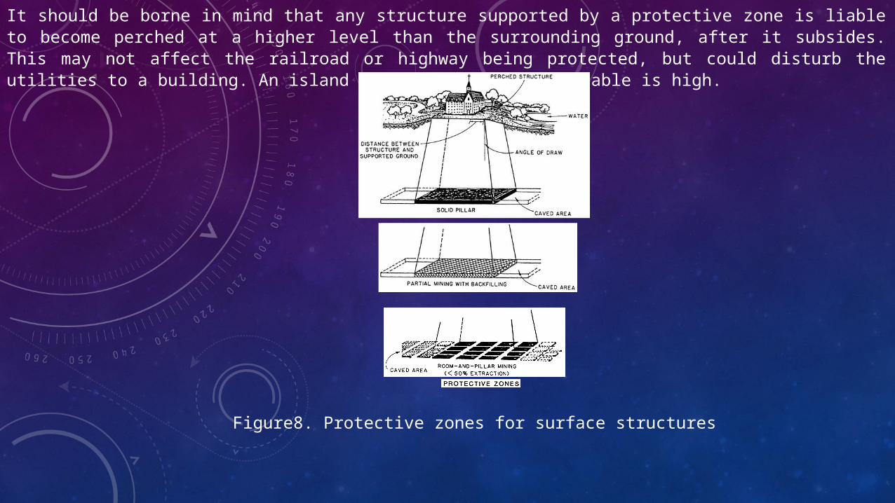
It should be borne in mind that any structure supported by a protective zone is liable to become perched at a higher level than the surrounding ground, after it subsides. This may not affect the railroad or highway being protected, but could disturb the utilities to a building. An island may form if the water table is high.
Figure8. Protective zones for surface structures
2. Use of sized pillars, that is, the pillar width between panels is adjusted so as to uniformly lower the ground surface
3. Mining subcritical widths, so that the maximum subsidence is reduced.
Backfilling: This may be done using hydraulic or pneumatic techniques, which reduce the amount of subsidence, but do not eliminate it entirely. It is a very effective method of mitigating subsidence effects, since it not only minimizes the ground-deformation forces but also conserves the hydrologic regime. Cost effectiveness studies should consider the beneficial effect on the environment such as reduced acid-water drainage, savings in waste disposal and reforestation, prevention of refuse fires, reduced ground fissuring and escape of mine gases, as well as the advantages of long-term strata stability and decreased roof support. Railroads, canals, sewers, and streams experience smaller gradient changes. Hydraulic flushing may also cool the mine air, which is desirable in deep mines. Backfilling may become essential in flat regions with a high water table to prevent flooding, and in areas reclaimed from water bodies (e.g., in The Netherlands).
a. Harmonious Mining: The technique entails superimposing compressive surface strains on the tensile strains induced by another longwall face in a manner that they move along together. This may be accomplished by staggering two simultaneously worked faces that advance at the same rate, with (1) multiple seams, in which one face is superjacent over another, and (2) single seams, where the panels adjoin.
b. Mine Layout or Configuration: Layout controls the strains experienced by the structure. It may be possible to locate the panel with respect to the building in such a manner as to expose it to deformations that it can withstand (Fig.10.6.17). In some cases, it may be best to stop short of taking all the coal; the loss may not be excessive if the seam is shallow.
c. Extraction Rate: Face advance cannot be readily altered in mining, and its range is generally limited with the available equipment. A faster rate is desirable in unfractured, viscoelastic strata because it lowers the tensile peak and moves it closer toward the working face. However, in fractured, clastic rocks (such as over previously mined beds), rapid face advance may accentuate displacements and strains and thus induce greater damage.
Postmining Stabilization
These techniques have been used in the United States and may extend over large areas (tens of acres or hectares) or be restricted to support a specific structure.
Areal: The four main methods used include:
1. Backfilling, which may be conducted
a. Hydraulically.
b. Pneumatically.
In either case the procedure may be (1) controlled, when the mine is accessible and barricades can be manually built, or (2) remote (blind), through boreholes when the openings cannot be entered, such as in abandoned mines.
A commonly used material for backfilling, both hydraulic and pneumatic, is fly ash because of its abundance at coal-fired power plants.
2. Grouting entails using a cementitious mixture and thus provides a stronger support. Additives used include Portland cement, pozzolanic mixtures, or organic compounds.
a. Gravity grouting is used to simply fill the mine void to whatever extent possible. There is little control, although a perimeter wall may first be built with a thick grout, which is then filled with an expansive grout to achieve good roof contact.
b. Pressure grouting is needed if a number of joints need to be filled or roof caving has occurred.
c. Bag grouting is a new development (Singh, 1985), and entails lowering a bag through a 6-in. (150-mm)-diameter borehole and filling that with grout until roof contact is obtained.
Grouting under important buildings requires special care
3. Excavation and fill placement is only feasible in shallow abandoned mines, with no surface obstructions to excavation. The entire overburden and coal are removed and replaced with compacted fill. Flooded mines may yield large quantities of acid water.
4. Blasting of the roof and floor to fill the cavity is a patented technique (Patent No. 1 004 419), which has not been used recently (Gray et al., 1974). Over time, the broken rock compresses, but the movements may be expected to be gradual and evenly distributed.
Site Specific: These techniques are mostly used to support isolated structures.
1. Grout columns may be built remotely, but floor and column strengths are variable. Water may impede construction.
2. Piers and cribs may be constructed in mine openings that are accessible, if the mine floor and roof are competent.
3. Deep foundations may be used with shallow workings. They are, however, liable to damage by lateral shear forces that may be experienced.
4. Groutcase supports entail placing casing between the mine roof and floor and filling it with grout. These supplement existing coal pillars.
Architectural and Structural Design
Orientation: It is preferable to have the long axis of the building parallel to the subsidence contours. If a fault exists nearby, the shorter axis should be oriented perpendicular to the fault.
Location: Faults tend to concentrate ground strains, hence structures should be located at least 50 ft (15 m) away.
A single building should not be constructed on dissimilar soils, owing to the possibility of differential deformations or settlements.
Subsidence-Resistant Construction: This technique has received considerable attention in the literature. It may be discussed under four major construction categories:
1. Rigid in which both the foundation and superstructure are rigid in design. Often the foundations are highly reinforced concrete rafts or beams, capable of withstanding ground displacements and curvature. The structures generally span or cantilever over a subsidence wave. Foundations are of small plan area. Elevator shafts and the like are designed with extra clearances.
2. Flexible design permits slab foundations for small buildings such as houses. The slab should preferably be less than 60 ft (18 m) along the side, poured in a single operation, without joints, and finished close to ground level. It is generally underlain by granular material. Reinforcement should be near both the top and bottom so as to accommodate tensile and compressive strains.
If the building has a basement, there should be an open gap around it or filled with a compressible or granular material. Larger buildings may have rollers or slip-joints between the superstructure and foundation. Trenches around structures absorb some of the strains.
3.Semi-flexible designs are used in instances where the structures can tolerate minor damage, such as some warehouses. These do not strictly adhere to the rigid or flexible criteria outlined above. It may be more cost effective to perform minor repairs as required than employ these more expensive designs.4. Use of releveling devices, such as jacks, to prevent tilting. Excessive tilt may cause the gap between adjacent buildings to be reduced to the extent that they touch.Gaps need to be provided between all buildings to allow for both compression and tilt. Other precautions that are helpful, depending on design philosophy, are (Chen et al., 1974; Anon.,
1977)
a. Provide expansion joints to accommodate ground movements and thermal expansion.b. Minimize the number of door and window openings and use flexible frames; their location should not significantly weaken the structure; do not
position front and back doors opposite each other.c. Avoid weak skin materials within rooms; partitions between building segments should be strong; instead of plaster on ceilings and walls, use
plaster board.d. Floors and roof should be secured to the walls.e. Allow for tensile strains at all structural connections; movements should be possible for staircases.f. Exclude masonry arches.g. Do not have comer or bay windows or porches.h. Detach outbuildings from the main buildingi. Provide excessive falls for gutters.j. Do not pave immediately adjoining buildings; use bi-tuminous type materials for paving where necessary (e.g., driveways).k. Employ flexible damp-proof courses (e.g., bitumen).l. Use light fences around properties rather than walls.m. Replace rigid retaining walls with earth banks.
Modification of Existing Structures: Total repair expenses may sometimes be reduced if a building is suitably modified prior to its experiencing ground movements. Possible alterations include (Chen et al., 1974; Kratzsch, 1983)
1. Cutting out a part of a house or removing an entire housefrom a row of buildings; unit lengths should be about 60 ft (18m), with cuts extending into trenches, and gaps bridged with flexible materials; preferably locate cuts in connection corridors or unit divisions.
2. Digging trenches around a building (and filling with compressive material weaker than the surrounding soil) to below foundation level, without disturbing the foundation; trenches may be covered, if desired, with concrete slabs that do not butt.
3. Slotting rigid pavements or floors, and even superstructures (generally wood, brick, or stone do not present difficulties; concrete may).
4. Introducing slip planes, especially in new buildings.
Comprehensive Planning
It is desirable to plan both the surface land use and the mine with full knowledge of the requirements of each. Deep cuts for highways, railroads, or other structures, or excavations for utility tunnels or basements, may reduce the competent overburden thickness above the old workings to induce subsidence. This type of situation can be prevented with planning.
For planning or any other measure to be successfully implemented, it is paramount that everyone affected by subsidence fully comprehend what is being done and why. Therefore, an intensive effort of public education about the subject is in order. This should not only be directed towards the general populace, but also the mine operating personnel, builders and developers, government officials at all levels, and civic groups.
Four situations (Anon., 1977) may be identified, each of which requires a slightly different approach to planning:
1. Existing subsidence potential, existing development.2. Existing subsidence potential, future development.3. Future mining area, existing development.4. Future mining area, future development.Essentially all these approaches entail either coordination or control of both the surface and subsurface development.
Coordination of Surface/Underground Development: Although not a comprehensive list, typical of the principles that may be followed are
1. Avoid construction near outcrops or faults.2. Build only specially designed structures over shallow workings; surface effects are magnified as the depth decreases.3. Locate buildings above steeply dipping seams since the strains induced are reduced.4. Erect communications or other significant structures in unmined or completely subsided areas.5. Alter routes of highways, railroads, canals, and other structures to suit coal conditions (e.g., over want areas or near fault
planes); subsequent costs for lowering may be thereby reduced.6. Site linear structures (e.g., canals, railroads) so that they can be uniformly lowered along their entire length; locks may be
located over un-minable zones, although massive lock structures can be dropped without significant damage.7. Avoid building important structures near mine boundaries since coordination with several mine operators and surface land
owners is onerous; also boundary pillars may introduce higher stresses.Collaboration between the mining companies and surface owners and developers is essential in regional or zonal planning, otherwise problems will arise.
Land Use/Development Control: Development of land areas overlying mines must be economically justifiable as well as socially and culturally acceptable. This implies that often regional plans should not only be discussed with mine and surface owners, but also be open to public comment prior to adoption. Changes in these plans also deserve an equally protracted treatment.
Federal, state, regional, county, and local government authorities exert considerable control over development of land that is potentially liable to damage due to subsidence through these means:
1. Surface Mining Reclamation and Control Act (SMRCA) of 1977 (Public Law 95-87).2. Environmental impact requirements.3. Zoning and subdivision regulations.4. Building provisions (issuance of permits).5. Mining regulations.6. Safety requirements.7. Insurance needs.8. Investigative requirements for public buildings (e.g.,Pennsylvania’s Act 17 of 1972).9. Special local ordinances.10. Interagency coordination.Perhaps in the future, it will be mandated that mine operators prepare plans that depict predicted subsidence locations, extent, trough centers, maximum subsidence, values and direction of tilt, compression and extension zones, and other pertinent data. These could then be circulated to building authorities, highway commissions, railroads, water supply and other utility agencies, pipeline operators, and others who may be affected for comments and suggestions (within strict time limitations). On the other hand, these groups as well as builders/developers should be required to incorporate proper precautions in the design of their respective structures. In extreme cases, construction may be barred from particularly risky areas, and these lands used for parks, forest preserves, and open spaces.

Thank You


![Coal Mine Subsidence Compensation Act 2017 - … · Page 2 Coal Mine Subsidence Compensation Act 2017 No 37 [NSW] Contents Page 18 Failure of proprietor of coal mine to comply with](https://img.pdfslide.us/doc/110x75/5b82c9427f8b9a31608bc8b3/coal-mine-subsidence-compensation-act-2017-page-2-coal-mine-subsidence-compensation.jpg)