Embed Size (px)
Citation preview
1
INTRODUCTION
HISTORY
Remotely controlled robots have been being used when a human cannot be present on site
to perform a job because it is dangerous, far away, or inaccessible. Like in case of
detecting land mines. Rather than following a predetermined sequence of movements, a
robot is controlled from a distance by a human operator. The robot may be in another
room or another country, or may be on a very different scale to the operator. In case of a
DTMF controlled robot, the range is the mobile operator’s coverage area. Dual-tone
multi-frequency (DTMF) signaling is used for telecommunication signaling over analog
telephone lines in the voice-frequency band between mobile handsets and other
communications devices and the switching center. The version of DTMF used for
telephone tone dialing is known by the trademarked term Touch-Tone (canceled March
13, 1984), and is standardized by ITU-T Recommendation Q.23. It is also known in the
UK as MF4. Other multi-frequency systems are used for signaling internal to the
telephone network.
In the combat zone, the process is referred to as mine clearance. The priority is to breach
the minefield quickly to create a safe path for troops or ships. Speed is vital, both for
tactical reasons and because units attempting to breach the minefield may be under
enemy fire. In this situation, it is accepted that mine clearance will be imperfect and there
may be casualties from undiscovered mines. Correspondingly, in these mine clearance
operations, the methods that are applied for detection and removal are quicker, but not
exact. These methods include those that detect and remove in a single action
The first step in manual demining is to scan the area with metal detectors, which are
sensitive enough to pick up most mines but which also yield about one thousand false
positives for every mine,and cannot detect landmines with very low metal content.
(While some mines have significant metallic content and are fairly easy to detect with
metal detectors, many anti-personnel mines and some anti-tank mines have a very low
metal content and are much more challenging to locate). Areas where metal is detected

2
are carefully probed to determine if a mine is present, and must continue until the object
that set off the metal detector is found.
Toward the end of the 19th century, many scientists and engineers used their growing
knowledge of electrical theory in an attempt to devise a machine which would pinpoint
metal. The use of such a device to find ore-bearing rocks would give a huge advantage to
any miner who employed it. The German physicist Heinrich Wilhelm Dove invented the
induction balance system, which was incorporated into metal detectors a hundred years
later. Early machines were crude, used a lot of battery power, and worked only to a very
limited degree. Alexander Graham Bell used such a device to attempt to locate a bullet
lodged in the chest of American President James Garfield in 1881; the attempt was
unsuccessful because the metal bed Garfield was lying on confused the detector.

3
GENERAL CONCEPTS
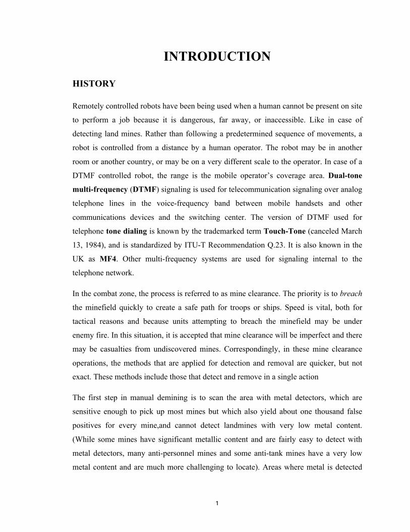
In this project the robot, is controlled by a mobile phone that makes call to theGSM modem attached to the robot in the course of the call, if any button is pressed control corresponding to the button pressed is heard at the other end of the call. This tone is called dual tone multi frequency tome (DTMF) robot receives this DTMF tone with the help of phone stacked in the robot The received tone is processed by the 89c51 microcontroller with the help of DTMF decoder MT8870 the decoder decodes the DTMF tone in to its equivalent binary digit and this binary number is send to the microcontroller, the microcontroller is preprogrammed to take a decision for any give input and outputs its decision to motor drivers in order to drive the motors for forward or backward motion or a turn. The mobile that makes a call to the mobile phone stacked in the robot acts as a remote. So this simple robotic project does not require the construction of receiver and transmitter units. DTMF signaling is used for telephone signaling over the line in the voice frequency band to the call switching center. The version of DTMF used for telephone dialing is known as touch tone. DTMF assigns a specific frequency (consisting of two separate tones) to each key s that it can easily be identified by the electronic circuit. The signal generated by the DTMF encoder is the direct al-gebric submission, in real time of the amplitudes of two sine(cosine) waves of different frequencies, i.e. ,pressing 5 will send a tone made by adding 1336hz and 770hz to the other end of the mobile. The tones and assignments in a dtmf system shown below
The signals generated are used by 89c51 as control inputs to the motor driver chip L293D
which controls the direction of the robot.
4
A metal detector is attached at the end of the vehicle to detect the mine like objects
proactively. And give the necessary signal to the operator. For better navigation, a
wireless camera is implemented which sends the high quality pictures of the site.

5
ADVANTAGES
• Simple design and construction
• Reliable control mechanism
DISADVANTAGES
• Time lag in DTMF communication
• Limitation in the range of remote surveillance owning to limited range of wireless
transmission of camera footages.
• Performance of the DC motor limit the performance of the Robot
• The metal detection cannot be performed beyond a particular distance.
6
DETAILS
Dual-tone multi-frequency
Dual Tone Multi-Frequency, or DTMF, is a method for instructing a telephone switching
system of the telephone number to be dialed, or to issue commands to switching systems
or related telephony equipment.
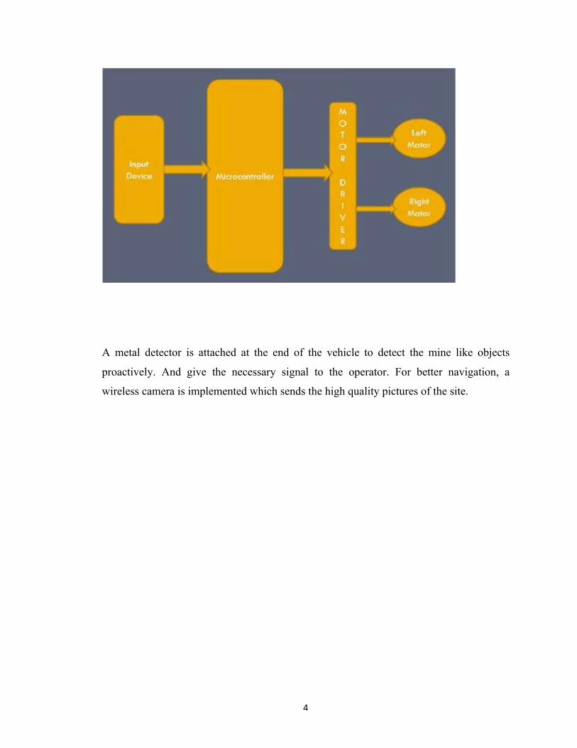
The DTMF system uses eight different frequency signals transmitted in pairs to represent
sixteen different numbers, symbols and letters - as detailed below.
Working of IC MT8870:
The MT-8870 is a full DTMF Receiver that integrates both band split filter and decoder
functions into a single 18-pin DIP. Its filter section uses switched capacitor technology
for both the high and low group filters and for dial tone rejection. Its decoder uses digital
counting techniques to detect and decode all 16 DTMF tone pairs into a 4-bit code.
External component count is minimized by provision of an on-chip differential input
amplifier, clock generator, and latched tri-state interface bus. Minimal external
components required include a low-cost 3.579545 MHz crystal, a timing resistor, and a
timing capacitor. The MT-8870-02 can also inhibit the decoding of fourth column digits.
MT-8870 operating functions include a band split filter that separates the high and low
tones of the received pair, and a digital decoder that verifies both the frequency and
duration of the received tones before passing the resulting 4-bit code to the output bus.

7
The low and high group tones are separated by applying the dual-tone signal to the inputs
of two 6th order switched capacitor band pass filters with bandwidths that correspond to
the bands enclosing the low and high group tones.
8
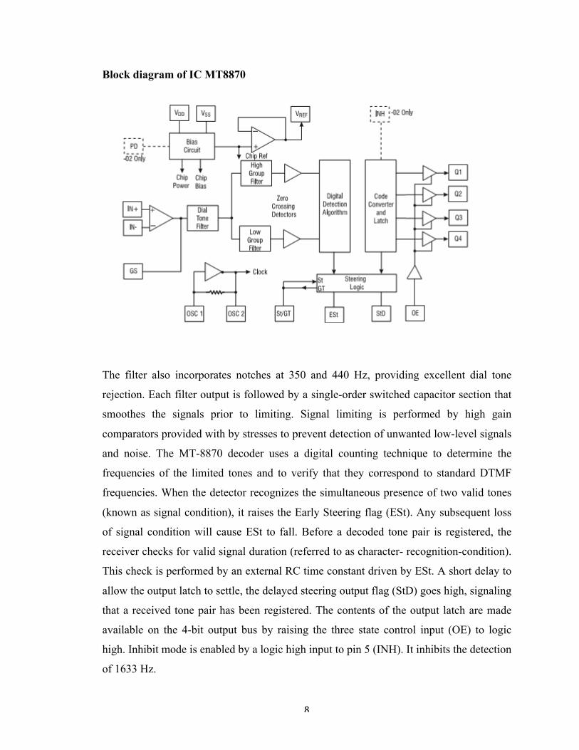
Block diagram of IC MT8870
The filter also incorporates notches at 350 and 440 Hz, providing excellent dial tone
rejection. Each filter output is followed by a single-order switched capacitor section that
smoothes the signals prior to limiting. Signal limiting is performed by high gain
comparators provided with by stresses to prevent detection of unwanted low-level signals
and noise. The MT-8870 decoder uses a digital counting technique to determine the
frequencies of the limited tones and to verify that they correspond to standard DTMF
frequencies. When the detector recognizes the simultaneous presence of two valid tones
(known as signal condition), it raises the Early Steering flag (ESt). Any subsequent loss
of signal condition will cause ESt to fall. Before a decoded tone pair is registered, the
receiver checks for valid signal duration (referred to as character- recognition-condition).
This check is performed by an external RC time constant driven by ESt. A short delay to
allow the output latch to settle, the delayed steering output flag (StD) goes high, signaling
that a received tone pair has been registered. The contents of the output latch are made
available on the 4-bit output bus by raising the three state control input (OE) to logic
high. Inhibit mode is enabled by a logic high input to pin 5 (INH). It inhibits the detection
of 1633 Hz.
9
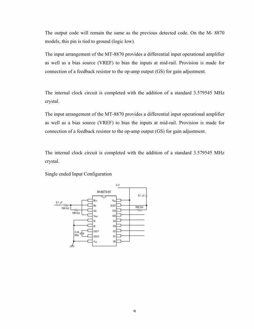
The output code will remain the same as the previous detected code. On the M- 8870
models, this pin is tied to ground (logic low).
The input arrangement of the MT-8870 provides a differential input operational amplifier
as well as a bias source (VREF) to bias the inputs at mid-rail. Provision is made for
connection of a feedback resistor to the op-amp output (GS) for gain adjustment.
The internal clock circuit is completed with the addition of a standard 3.579545 MHz
crystal.
Single ended Input Configuration

10
Tone Decoding
11
89C61 8-bit Flash microcontroller
The Intel 8051 is Harvard architecture, single chip microcontroller (µC) which was
developed by Intel in for use in embedded systems. It uses CMOS technology for low
power consumption
In addition, the devices are static designs which offer a wide range of operating
frequencies down to zero. Two software selectable The Philips microcontrollers
described in this data sheet are modes of power reduction — idle mode and power-down
mode high-performance static 80C51 designs. They are manufactured in are available.
The idle mode freezes the CPU while allowing the an advanced CMOS process and
contain a non-volatile Flash RAM, timers, serial port, and interrupt system to continue
program memory that is programmable in parallel (via a parallel functioning. The power-
down mode saves the RAM contents but programmer) or In-System Programmable (ISP)
via boot loader. freezes the oscillator, causing all other chip functions to be They support
both 12-clock and 6-clock operation. inoperative. Since the design is static, the clock can
be stopped The P89C60X2 and P89C61X2 contain 512 bytes RAM and without loss of
user data. Then the execution can be resumed from 1024 bytes RAM respectively, 32 I/O
lines, three 16-bit the point the clock was stopped. counter/timers, a six-source, four-
priority level nested interrupt structure, a serial I/O port for either multi-processor
communications, I/O expansion or full duplex UART, and on-chip.

12
Block Diagram

13
FEATURES
• LQFP, PLCC, and DIP packages
• 80C51 Central Processing Unit
• Dual Data Pointers
– 64 kbytes Flash
• Three security bits
– 512 bytes RAM (P89C60X2)
– 1024 bytes RAM (P89C61X2)
• Four interrupt priority levels
– Boolean processor
• Six interrupt sources
– Fully static operation
• Four 8-bit I/O ports
• In-System Programmable (ISP) Flash memory
• Full-duplex enhanced UART
• 12-clock operation with selectable 6-clock operation (via software
– Framing error detection
or via parallel programmer)
– Automatic address recognition
•Memory addressing capability

14
• Three 16-bit timers/counters T0, T1 (standard 80C51) and
– Up to 64 kbytes ROM and 64 kbytes RAM
additional T2 (capture and compare)
• Power control modes:
• Programmable clock-out pin
– Clock can be stopped and resumed
•Watchdog timer
– Idle mode
– Power-down mode • Asynchronous port reset
• Two speed ranges • Low EMI (inhibit ALE, 6-clock mode)
– 0 to 20 MHz with 6-clock operation
•Wake-up from Power Down by an external interrupt
– 0 to 33 MHz with 12-clock operation
The following table illustrates the correlation between operating mode, power supply and
maximum external clock frequency:

15
Logic Symbol
16
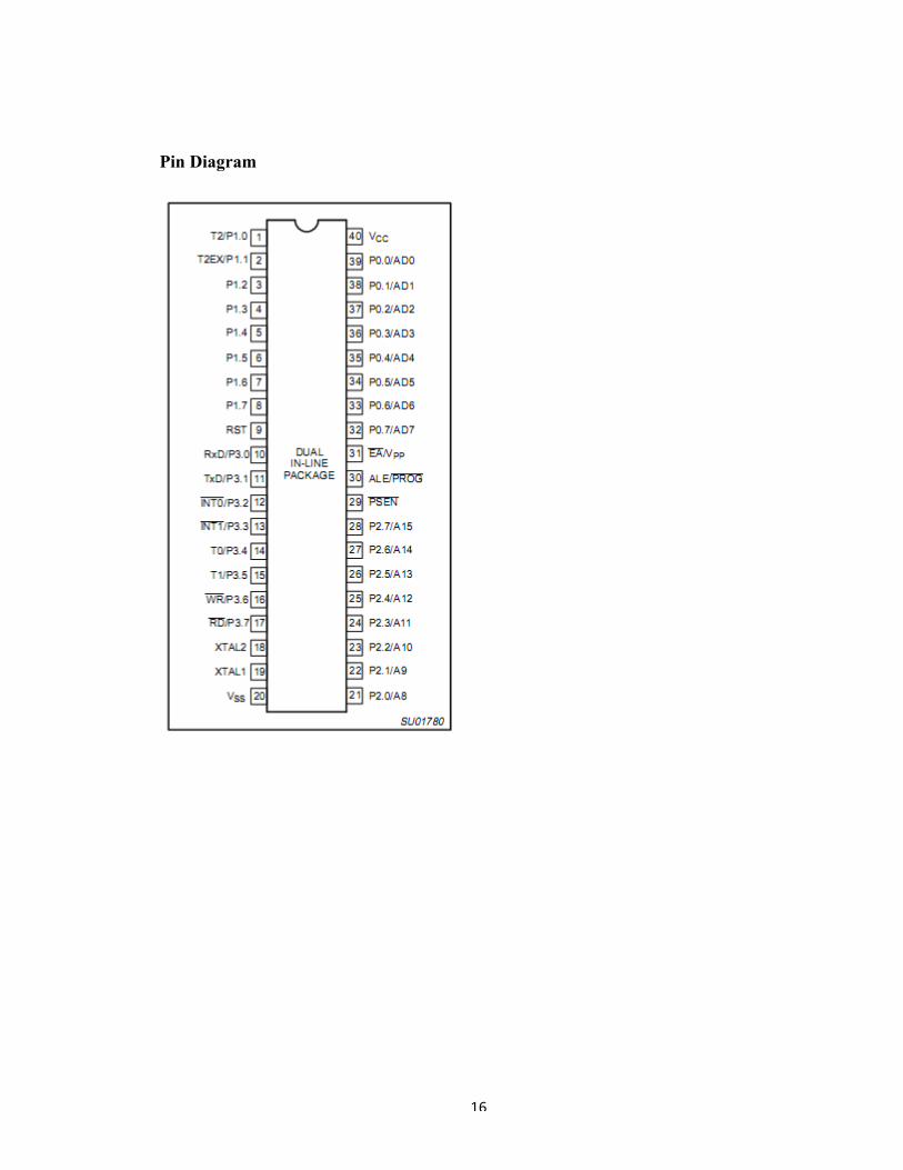
Pin Diagram

17
FLASH EPROM MEMORY
• Programmable security for the code in the Flash.
• 10,000 minimum erase/program cycles for each byte.
GENERAL DESCRIPTION
The P89C60X2/61X2 Flash memory augments EPROM functionality • 10-year minimum
data retention. with in-circuit electrical erasure and programming. The Flash can be read
and written as bytes. The Chip Erase operation will erase the entire program memory.
The Block Erase function can erase any
FLASH PROGRAMMING AND ERASURE
Flash block. In-system programming (ISP) and standard parallel There are two methods
of erasing or programming of the Flash programming are both available. On-chip erase
and write timing memory that may be used. First, the on-chip ISP boot loader may be
ngeneration contribute to a user friendly programming interface. invoked. Second, the
Flash may be programmed or erased using The P89C60X2/61X2 Flash reliably stores
memory contents even parallel method by using a commercially available EPROMb after
10,000 erase and program cycles. The cell is designed to programmer. The parallel
programming method used by these optimize the erase and programming mechanisms. In
addition, the devices is similar to that used by EPROM 87C51, but it is not combination
of advanced tunnel oxide processing and low internal identical, and the commercially
available programmer will need to electric fields for erase and programming operations
produces have support for these devices. reliable cycling. The P89C60X2/61X2 uses a +5
V V supply to PP perform the Program/Erase algorithms (12 V tolerant).

18
FLASH MEMORY CHARACTERISTICS
Flash User Code Memory Organization
The P89C60X2/61X2 contains 64 kbytes Flash user code program memory organized
into 4-kbyte blocks (see Figure 1).
Boot ROM
When the microcontroller programs its Flash memory during ISP, all of the low level
details are handled by code that is contained in a 1 kbyte BootROM. BootROM
operations include: erase block, program byte, verify byte, program security bit, etc.
Clock Mode
The clock mode feature sets operating frequency to be 1/12 or 1/6 of the oscillator
frequency. The clock mode configuration bit, FX2, is located in the Security Block (See
Table 1). FX2, when programmed, will override the SFR clock mode bit (X2) in the
CKCON register. If FX2 is erased, then the SFR bit (X2) may be used to select between
6-clock and 12-clock mode.
FEATURES
The P89C60X2/61X2 contains 64 kbytes Flash user code program
• Flash EPROM internal program memory with Block Erase.
memory organized into 4-kbyte blocks (see Figure 1).
• Internal 1-kbyte fixed BootROM, containing low-level in-system
Boot ROM
programming routines and a default serial loader.
When the microcontroller programs its Flash memory during ISP, all

19
• Loader in BootROM allows in-system programming via the serial of the low level
details are handled by code that is contained in a port. 1 kbyte BootROM. BootROM
operations include: erase block, program byte, verify byte, program security bit, etc.
• Up to 64 kbytes external program memory if the internal program memory is disabled
(EA = 0).
Clock Mode
• Programming and erase voltage +5 V (+12 V tolerant). The clock mode feature sets
operating frequency to be 1/12 or 1/6 of the oscillator frequency. The clock mode
configuration bit, FX2, is
• Read/Programming/Erase using ISP: located in the Security Block (See Table 1). FX2,
when programmed,
– Byte Programming (8 s). will override the SFR clock mode bit (X2) in the CKCON
register. If
FX2 is erased, then the SFR bit (X2) may be used to select between
– Typical erase times:
6-clock and 12-clock mode.
Block Erase (4 kbytes) in 3 seconds.
Full-chip erase in 15 seconds.
• Parallel programming with 87C51 compatible hardware interface to programmer.
• Programmable security for the code in the Flash.
• 10,000 minimum erase/program cycles for each byte.
• 10-year minimum data retention.
20
DC GEARED MOTORS
INTRODUCTION - DC MOTOR
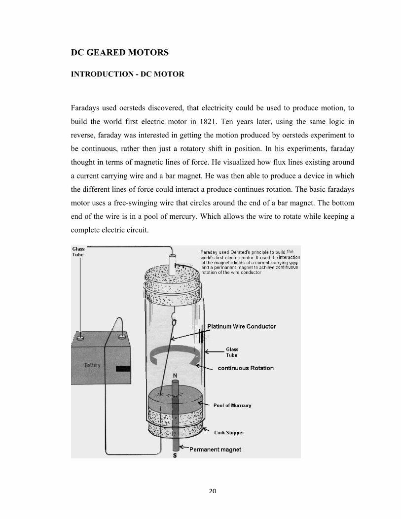
Faradays used oersteds discovered, that electricity could be used to produce motion, to
build the world first electric motor in 1821. Ten years later, using the same logic in
reverse, faraday was interested in getting the motion produced by oersteds experiment to
be continuous, rather then just a rotatory shift in position. In his experiments, faraday
thought in terms of magnetic lines of force. He visualized how flux lines existing around
a current carrying wire and a bar magnet. He was then able to produce a device in which
the different lines of force could interact a produce continues rotation. The basic faradays
motor uses a free-swinging wire that circles around the end of a bar magnet. The bottom
end of the wire is in a pool of mercury. Which allows the wire to rotate while keeping a
complete electric circuit.

21
BASIC MOTOR ACTION
Although Faraday's motor was ingenious. It could not be used to do any practical work.
This is because its drive shaft was enclosed and it could only produce an internal orbital
motion. It could not transfer its mechanical energy to the outside for deriving an external
load. However it did show how the magnetic fields of a conductor and a magnet could be
made to interact to produce continuous motion. Faradays motor orbited its wire rotor
must pass through the magnet’s lines of force.

22
When a current is passes through the wire ,circular lines of force are produced around the
wire. Those flux lines go in a direction described by the left-hand rule. The lines of force
of the magnet go from the N pole to the S pole You can see that on one side of the wire,
the magnetic lines of force are going in the opposite direction as a result the wire, s flux
lines oppose the magnet’s flux line since flux lines takes the path of least resistance, more
lines concentrate on the other side of the wire conductor, the lines are bent and are very
closely spaced. The lines tend to straighten and be wider spaced. Because of this the
denser, curved field pushes the wire in the opposite direction.
The direction in which the wire is moved is determined by the right hand rule. If the
current in the wire went in the opposite direction. The direction of its flux lines would
reverse, and the wire would be pushed the other way.
RULES FOR MOTOR ACTION
The left hand rule shows the direction of the flux lines around a wire that is carrying
current. When the thumb points in the direction of the magnetic lines of force. The right
hand rule for motors shows the direction that a current carrying wire will be moved in a
magnetic field. When the forefinger is pointed in the direction of the magnetic field lines,
and the centre finger is pointed in the direction of the current in the wire the thumb will
point in the direction that the wire will be moved.

23

24
TORQUE AND ROTATORY MOTION
In the basic action you just studied the wire only moves in a straight line and stops
moving once out of the field even though the current is still on. A practical motor must
develop a basic twisting force called torque loop. We can see how torque is produced. If
the loop is connected to a battery. Current flows in one direction one side of the loop, and
in the opposite direction on the other. Therefore the concentric direction on the two sides.
If we mount the loop in a fixed magnetic field and supply the current the flux lines of the
field and both sides of the loop will interact, causing the loop to act like a lever with a
force pushing on its two sides in opposite directions. The combined forces result in
turning force, or torque because the loop is arranged to piot on its axis. In a motor the
loop that moves in the field is called an armature or rotor. The overall turning force on
the armature depends upon several factors including field strength armature current
strength and the physical construction of the armature especially the distance from the
loop sides to the axis lines. Because of the lever action the force on the sides are further
from the axis; thus large armature will produce greater torques.

25
In the practical motor the torque determines the energy available for doing useful work.
The greater the torque the greater the energy. If a motor does not develop enough torque
to pull its load it stalls.
PRODUCING CONTINUOUS ROTATION
The armature turns when torque is produced and torque is produced as long as the fields
of the magnet and armature interact. When the loop reaches a position perpendicular to
the field, the interaction of the magnetic field stops. This position is known as the neutral
plane. In the neutral plane, no torque is produced and the rotation of the armature should
stop; however inertia tends to keep a moving object in the motion even after the prime
moving force is removed and thus the armature tends to rotate past the neutral plane. But
when the armature continues o the sides of the loop start to swing back in to the flux
lines, and apply a force to push the sides of the loop back and a torque is developed in the

26
opposite direction. Instead of a continuous rotation an oscillating motion is produced
until the armature stops in the neutral plane.

27
To get continuous rotation we must keep the armature turning in the same direction as it
passes through the neutral plane .We could do this by reversing either the direction of the
current flow through the armature at the instant the armature goes through the neutral
pole. Current reversals of this type are normally the job of circuit switching devices.
Since the switch would have to be synchronized with the armature, it is more logical to
build it into the armature then in to the field. The practical switching device, which can
change the direction of current flow through an armature to maintain continuous rotation,
is called a commutator.

28
THE COMMUTATOR
into two segment with each segment connected to an end of the armature loop. Power for
the armature from an external power source such as a battery is brought to the
commutator segments by means of brushes. The arrangement is almost identical to that
for the basic dc generator.
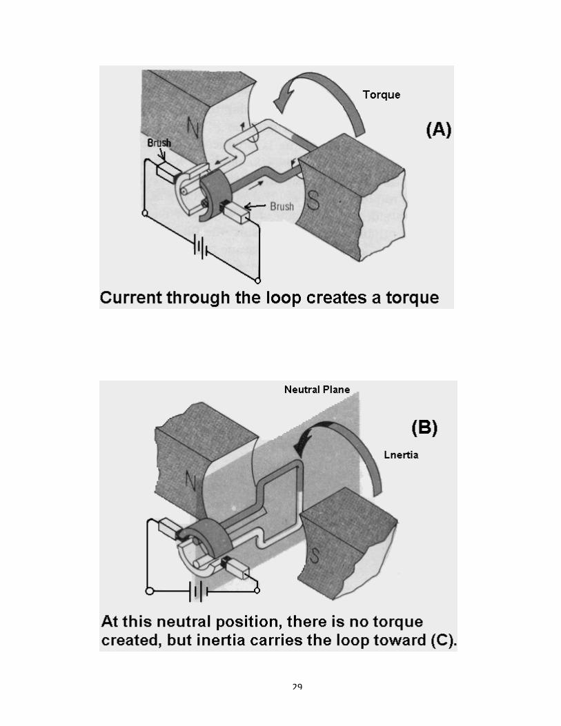
The logic behind the operation of the commutator is easy to see in the figures. You can
see in figure A that current flows into the side of the armature closest to the South Pole of
the field and out of the side closest to the North Pole. The interaction of the two fields
produces a torque in the direction indicated, and the armature rotates in that direction.
No torque is produced but the armature continues to rotate past the neutral plane due to
inertia. Notice that at the neutral position the commutator disconnects from the brushes
sides of the loop reverse positions. But the switching action of the commutator keeps the
direction of current flow through the armature the same as it was in the figure. A. Current
still flows into the armature side that is now closest to the South Pole.
Since the magnet’s field direction remains the same throughout the interaction of fields
after commutation keeps the torque going in the original direction; thus the same
direction of rotation is maintained.
As you can see in figure D, Inertia again carries the armature past neutral to the position
shown in the fig. A while communication keeps the current flowing in the direction that
continues to maintain rotation. In this way, the commutator keeps switching the current
through the loop, so that the field it produces always interacts with the pole field to
develop a continuous torque in the same direction.
29

30
31
THE ELEMANTARY D-C MOTOR
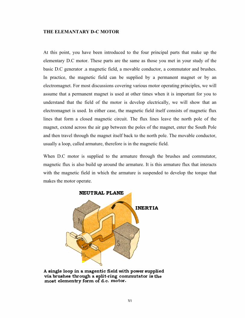
At this point, you have been introduced to the four principal parts that make up the
elementary D.C motor. These parts are the same as those you met in your study of the
basic D.C generator .a magnetic field, a movable conductor, a commutator and brushes.
In practice, the magnetic field can be supplied by a permanent magnet or by an
electromagnet. For most discussions covering various motor operating principles, we will
assume that a permanent magnet is used at other times when it is important for you to
understand that the field of the motor is develop electrically, we will show that an
electromagnet is used. In either case, the magnetic field itself consists of magnetic flux
lines that form a closed magnetic circuit. The flux lines leave the north pole of the
magnet, extend across the air gap between the poles of the magnet, enter the South Pole
and then travel through the magnet itself back to the north pole. The movable conductor,
usually a loop, called armature, therefore is in the magnetic field.
When D.C motor is supplied to the armature through the brushes and commutator,
magnetic flux is also build up around the armature. It is this armature flux that interacts
with the magnetic field in which the armature is suspended to develop the torque that
makes the motor operate.

32
The rover uses four dc geared motors at 50 rpm. The motors are brushed and direction
can be controlled by input dc signal.
The following graphics illustrate a two-pole DC motor.
A simple DC electric motor. When the coil is powered, a magnetic field is generated
around the armature. The left side of the armature is pushed away from the left magnet
and drawn toward the right, causing rotation.
The armature continues to rotate.

33
When the armature becomes horizontally aligned, the commutator reverses the direction
of current through the coil, reversing the magnetic field. The process then repeats.
When a current passes through the coil wound around a soft iron core, the side of the
positive pole is acted upon by an upwards force, while the other side is acted upon by a
downward force. According to Fleming's left hand rule, the forces cause a turning effect
on the coil, making it rotate. To make the motor rotate in a constant direction, "direct
current" commutators make the current reverse in direction every half a cycle (in a two-
pole motor) thus causing the motor to continue to rotate in the same direction.
34
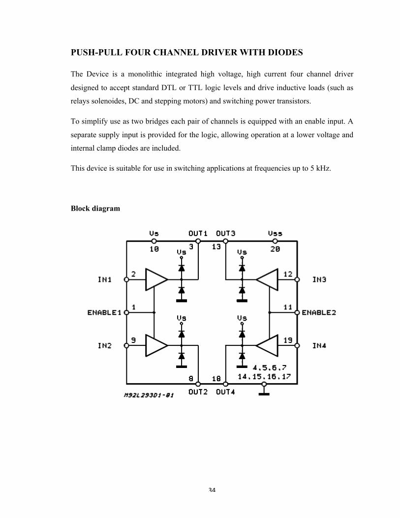
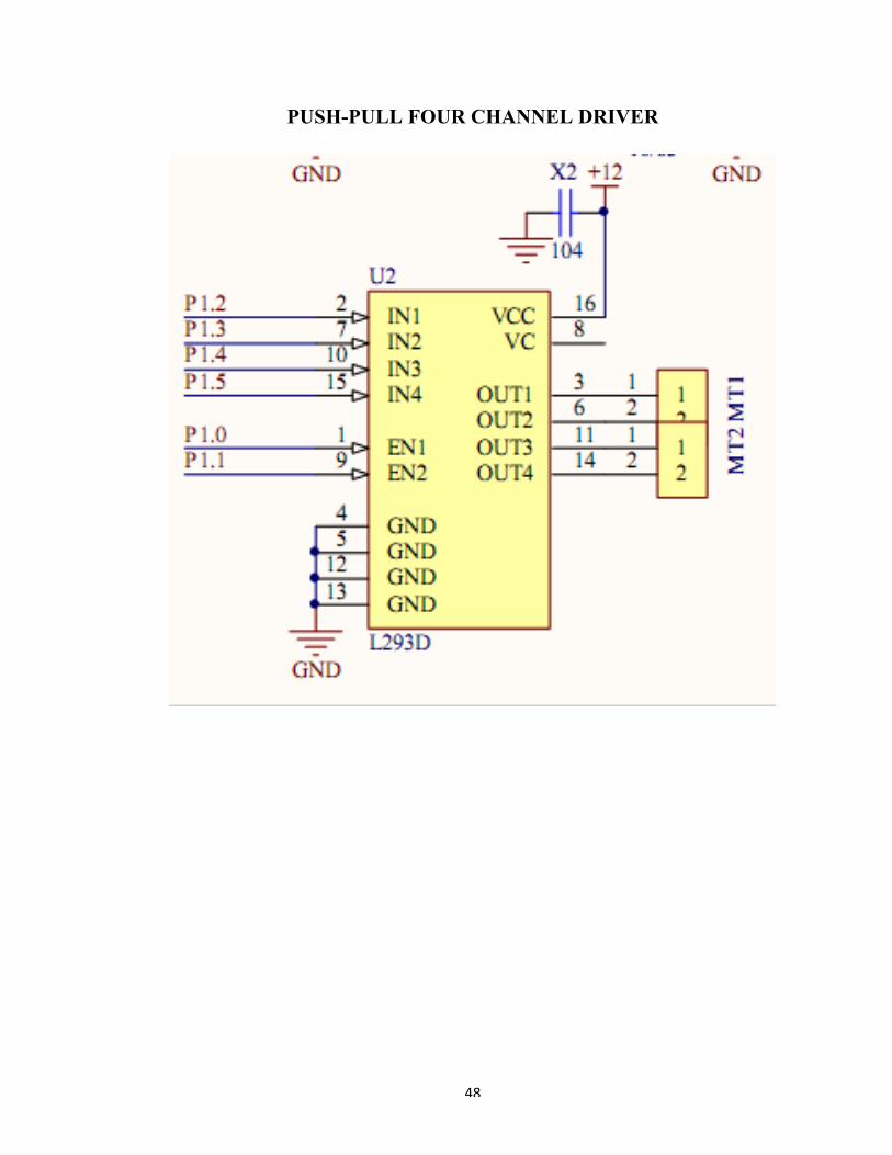
PUSH-PULL FOUR CHANNEL DRIVER WITH DIODES
The Device is a monolithic integrated high voltage, high current four channel driver
designed to accept standard DTL or TTL logic levels and drive inductive loads (such as
relays solenoides, DC and stepping motors) and switching power transistors.
To simplify use as two bridges each pair of channels is equipped with an enable input. A
separate supply input is provided for the logic, allowing operation at a lower voltage and
internal clamp diodes are included.
This device is suitable for use in switching applications at frequencies up to 5 kHz.
Block diagram

35
Truth table
Pin connectors

36
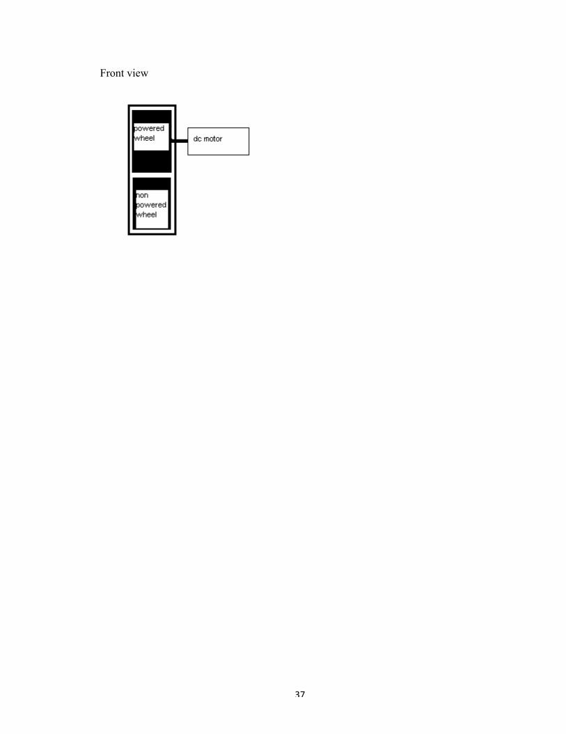
ROVER DESIGN
The rover is designed in a way that it can cross obstacles and gaps upto a limited size by
using tank style belt drive system. There are a total of ten wheels with five wheel on each
side.
Side view
Hence the belt transmits the power to each wheel and provides a surface for them to roll.
The sprockets in belt keep the wheels clung to it and the sawtooth structure on the outside
the belt provide enough grio for rover to move on any surface freely. This arrangement of
wheels makes crossing any obstacle easy and gives the rover enough ground clearance
from the inside.
The motors are connected to the wheels by their axles so there is no need of full length
axles.
37
Front view

38
Beat Balance Metal Detector
The simplest form of a metal detector consists of an oscillator producing an alternating
current that passes through a coil producing an alternating magnetic field. If a piece of
electrically conductive metal is close to the coil, eddy currents will be induced in the
metal, and this produces an alternating magnetic field of its own. If another coil is used to
measure the magnetic field (acting as a magnetometer), the change in the magnetic field
due to the metallic object can be detected.
39
POWER SUPPLY
In flow in one direction only. When the anode of the diode is positive with respect
to its cathode, it is forward biased, allowing current to flow. But when its anode is
negative with alternating current the electron flow is alternate, i.e. the electron flow
increases to maximum in one direction, decreases back to zero. It then increases in the
other direction and then decreases to zero again. Direct current flows in one direction
only. Rectifier converts alternating current to respect to the cathode, it is reverse biased
and does not allow current to flow. This unidirectional property of the diode is useful for
rectification. A single diode arranged back-to-back might allow the electrons to flow
during positive half cycles only and suppress the negative half cycles. Double diodes
arranged back-to-back might act as full wave rectifiers as they may allow the electron
flow during both positive and negative half cycles. Four diodes can be arranged to make a
full wave bridge rectifier. Different types of filter circuits are used to smooth out the
pulsations in amplitude of the output voltage from a rectifier. The property of capacitor to
oppose any change in the voltage applied across them by storing energy in the electric
field of the capacitor and of inductors to oppose any change in the current flowing
through them by storing energy in the magnetic field of coil may be utilized. To remove
pulsation of the direct current obtained from the rectifier, different types of combination
of capacitor, inductors and resistors may be also be used to increase to action of filtering.
NEED OF POWER SUPPLY
Perhaps all of you are aware that a ‘power supply’ is a primary requirement for
the ‘Test Bench’ of a home experimenter’s mini lab. A battery eliminator can eliminate
or replace the batteries of solid-state electronic equipment and the equipment thus can be
operated by 230v A.C. mains instead of the batteries or dry cells. Nowadays, the use of
commercial battery eliminator or power supply unit has become increasingly popular as
power source for household appliances like transreceivers, record player, cassette players,
digital clock etc.

40
THEORY
USE OF DIODES IN RECTIFIERS:
Electric energy is available in homes and industries in India, in the form of
alternating voltage. The supply has a voltage of 220V (rms) at a frequency of 50 Hz. In
the USA, it is 110V at 60 Hz. For the operation of most of the devices in electronic
equipment, a dc voltage is needed. For instance, a transistor radio requires a dc supply for
its operation. Usually, this supply is provided by dry cells. But sometime we use a battery
eliminator in place of dry cells. The battery eliminator converts the ac voltage into dc
voltage and thus eliminates the need for dry cells. Nowadays, almost all-electronic
equipment includes a circuit that converts ac voltage of mains supply into dc voltage.
This part of the equipment is called Power Supply. In general, at the input of the power
supply, there is a power transformer. It is followed by a diode circuit called Rectifier. The
output of the rectifier goes to a smoothing filter, and then to a voltage regulator circuit.
The rectifier circuit is the heart of a power supply.
RECTIFICATION
Rectification is a process of rendering an alternating current or voltage into a
unidirectional one. The component used for rectification is called ‘Rectifier’. A rectifier
permits current to flow only during the positive half cycles of the applied AC voltage by
eliminating the negative half cycles or alternations of the applied AC voltage. Thus
pulsating DC is obtained. To obtain smooth DC power, additional filter circuits are
required.
A diode can be used as rectifier. There are various types of diodes. But,
semiconductor diodes are very popularly used as rectifiers. A semiconductor diode is a
solid-state device consisting of two elements is being an electron emitter or cathode, the

41
other an electron collector or anode. Since electrons in a semiconductor diode can flow in
one direction only-from emitter to collector- the diode provides the unilateral conduction
necessary for rectification. Out of the semiconductor diodes, copper oxide and selenium
rectifier are also commonly used.
FULL WAVE RECTIFIER
It is possible to rectify both alternations of the input voltage by using two diodes
in the circuit arrangement. Assume 6.3 V rms (18 V p-p) is applied to the circuit. Assume
further that two equal-valued series-connected resistors R are placed in parallel with the
ac source. The 18 V p-p appears across the two resistors connected between points AC
and CB, and point C is the electrical midpoint between A and B. Hence 9 V p-p appears
across each resistor. At any moment during a cycle of vin, if point A is positive relative
to C, point B is negative relative to C. When A is negative to C, point B is positive
relative to C. The effective voltage in proper time phase which each diode "sees" is in
Fig. The voltage applied to the anode of each diode is equal but opposite in polarity at
any given instant.
When A is positive relative to C, the anode of D1 is positive with respect to its
cathode. Hence D1 will conduct but D2 will not. During the second alternation, B is
positive relative to C. The anode of D2 is therefore positive with respect to its cathode,
and D2 conducts while D1 is cut off.
There is conduction then by either D1 or D2 during the entire input-voltage cycle.
Since the two diodes have a common-cathode load resistor RL, the output voltage
across RL will result from the alternate conduction of D1 and D2. The output waveform
vout across RL, therefore has no gaps as in the case of the half-wave rectifier.
42
The output of a full-wave rectifier is also pulsating direct current. In the diagram,
the two equal resistors R across the input voltage are necessary to provide a voltage
midpoint C for circuit connection and zero reference. Note that the load resistor RL is
connected from the cathodes to this center reference point C.
An interesting fact about the output waveform vout is that its peak amplitude is
not 9 V as in the case of the half-wave rectifier using the same power source, but is less
than 4½ V. The reason, of course, is that the peak positive voltage of A relative to C is
4½ V, not 9 V, and part of the 4½ V is lost across R.
Though the full wave rectifier fills in the conduction gaps, it delivers less than
half the peak output voltage that results from half-wave rectification.
BRIDGE RECTIFIER
A more widely used full-wave rectifier circuit is the bridge rectifier. It requires
four diodes instead of two, but avoids the need for a centre-tapped transformer. During
the positive half-cycle of the secondary voltage, diodes D2 and D4 are conducting and
diodes D1 and D3 are non-conducting. Therefore, current flows through the secondary
winding, diode D2, load resistor RL and diode D4. During negative half-cycles of the
secondary voltage, diodes D1 and D3 conduct, and the diodes D2 and D4 do not conduct.
The current therefore flows through the secondary winding, diode D1, load resistor RL
and diode D3. In both cases, the current passes through the load resistor in the same
direction. Therefore, a fluctuating, unidirectional voltage is developed across the load.

43
FILTRATION
The rectifier circuits we have discussed above deliver an output voltage that
always has the same polarity: but however, this output is not suitable as DC power supply
for solid-state circuits. This is due to the pulsation or ripples of the output voltage. This
should be removed out before the output voltage can be supplied to any circuit. This
smoothing is done by incorporating filter networks. The filter network consists of
inductors and capacitors. The inductors or choke coils are generally connected in series
with the rectifier output and the load. The inductors oppose any change in the magnitude
of a current flowing through them by storing up energy in a magnetic field. An inductor
offers very low resistance for DC whereas; it offers very high resistance to AC. Thus, a
series connected choke coil in a rectifier circuit helps to reduce the pulsations or ripples
to a great extent in the output voltage. The fitter capacitors are usually connected in
parallel with the rectifier output and the load. As, AC can pass through a capacitor but
DC cannot, the ripples are thus limited and the output becomes smoothed. When the
voltage across its plates tends to rise, it stores up energy back into voltage and current.
Thus, the fluctuations in the output voltage are reduced considerable. Filter network
circuits may be of two types in general:
CHOKE INPUT FILTER
If a choke coil or an inductor is used as the ‘first- components’ in the filter
network, the filter is called ‘choke input filter’. The D.C. along with AC pulsation from
the rectifier circuit at first passes through the choke (L). It opposes the AC pulsations but
allows the DC to pass through it freely. Thus AC pulsations are largely reduced. The
further ripples are by passed through the parallel capacitor C. But, however, a little nipple
remains unaffected, which are considered negligible. This little ripple may be reduced by
incorporating a series a choke input filters.
44
CAPACITOR INPUT FILTER
If a capacitor is placed before the inductors of a choke-input filter network, the
filter is called capacitor input filter. The D.C. along with AC ripples from the rectifier
circuit starts charging the capacitor C. to about peak value. The AC ripples are then
diminished slightly. Now the capacitor C, discharges through the inductor or choke coil,
which opposes the AC ripples, except the DC. The second capacitor C by passes the
further AC ripples. A small ripple is still present in the output of DC, which may be
reduced by adding additional filter network in series.
45
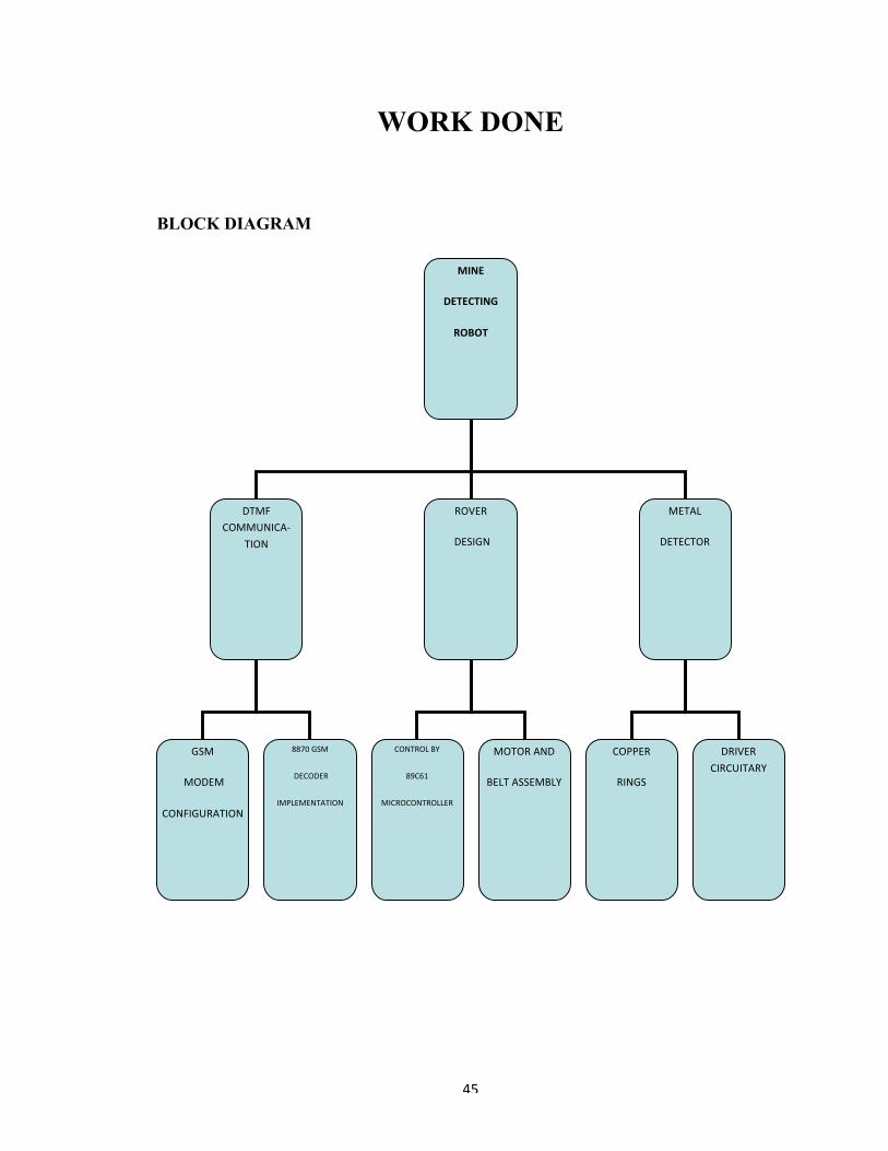
WORK DONE
BLOCK DIAGRAM
MINE
DETECTING
ROBOT
DTMFCOMMUNICA-
TION
ROVER
DESIGN
METAL
DETECTOR
CONTROLBY
89C61
MICROCONTROLLER
GSM
MODEM
CONFIGURATION
8870GSM
DECODER
IMPLEMENTATION
MOTORAND
BELTASSEMBLY
COPPER
RINGS
DRIVERCIRCUITARY

46
HARDWARE IMPLEMENTATION
CIRCUIT DIAGRAM
Microcontroller 89c61
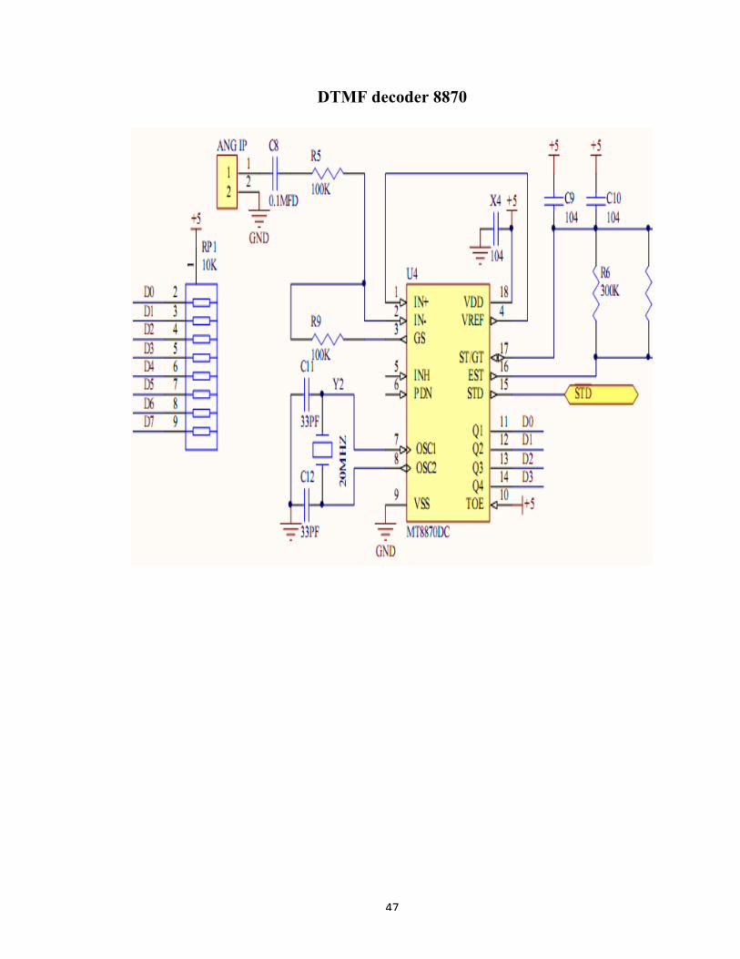
47
DTMF decoder 8870
48
PUSH-PULL FOUR CHANNEL DRIVER

49
SOFTWARE IMPLEMENTATION
PROGRAMMING ENVIRONMENT
Keil was founded in 1986 to market add-on products for the development tools provided
by many of the silicon vendors. Keil implemented the first C compiler designed from the
ground-up specifically for the 8051 microcontroller.
Keil provides a broad range of development tools like ANSI C compiler, macro
assemblers, debuggers and simulators, linkers, IDE, library managers, real-time operating
systems and evaluation boards for 8051, 251, ARM, and XC16x/C16x/ST10 families.
Keil development tools for the 8051 Microcontroller Architecture support every level of
software developer from the professional applications engineer to the student just
learning about embedded software development.
The industry-standard Keil C Compilers, Macro Assemblers, Debuggers, Real-time
Kernels, Single-board Computers, and Emulators support all 8051 derivatives and help
you get your projects completed on schedule.
The Keil 8051 Development Tools are designed to solve the complex problems facing
embedded software developers.
§ When starting a new project, simply select the microcontroller you use from the
Device Database and the µVision IDE sets all compiler, assembler, linker, and
memory options for you.
§ Numerous example programs are included to help you get started with the most
popular embedded 8051 devices.

50
§ The Keil µVision Debugger accurately simulates on-chip peripherals (I²C, CAN,
UART, SPI, Interrupts, I/O Ports, A/D Converter, D/A Converter, and PWM
Modules) of your 8051 device. Simulation helps you understand hardware
configurations and avoids time wasted on setup problems. Additionally, with
simulation, you can write and test applications before target hardware is available.
§ When you are ready to begin testing your software application with target
hardware, use the MON51, MON390, MONADI, or FlashMON51 Target Monitors,
the ISD51 In-System Debugger, or the ULINK USB-JTAG Adapter to download and
test program code on your target system

51
RESULTS
CONCLUSIONS
The DTMF based Mine Detecting Robot prototype will be taking off rapidly in the near
future. The need of the hour is to provide new standards.
The acceptance of this technology and its benefits if harnessed properly will lead to
increased area with land mines but also need to keep in mind the needs of government
agencies and not using this technology for unethical uses. The benefits of this technology
are far greater than the loop holes in the technology; by overcoming these we can
implement this technology with great BENEFITS.

52
REFERENCES AND BIBLIOGRAPHY
• Google.com
• Wikipedia.org
• Ieee.com
• Roboticsindia.com
• Alldatasheet.com
• Datasheetcatalog.com

53
Appendix
Attached are the datasheet related to all the IC s used in the project.