Embed Size (px)
Citation preview

1
Special Issue on Smart Antennas
MIMO Vector Channel Sounder Measurement for Smart Antenna System Evaluation*
R.S. THOMÄ, D. HAMPICKE, A. RICHTER, G. SOMMERKORN Ilmenau Technical University, Dept. of Electrical Engineering and Information Technology,
P.O. Box 100565, 98684 Ilmenau, GERMANY {tho,ham,ric,som}@e-technik.tu-ilmenau.de
U. TRAUTWEIN IMMS Inst. of Microelectronic and Mechatronic Systems, Langewiesener Str. 22, 98693 Ilmenau, GERMANY
Abstract. For the simulation and design of smart antenna transmission principles in mobile radio, precise knowledge of the time-variant directional multipath structure in various radio environments is required. In this paper, a new real-time multiple-input-multiple-output (MIMO) vector radio channel sounder is described, which uses multiple antennas at the transmitter as well as at the receiver position. The proposed MIMO measurement principle can be effectively exploited to estimate the propagation direction at both ends of the wireless link simultaneously, and thus, dramatically enhance overall resolution of the multiple path parameters. Applying a proper antenna architecture and the multidimensional unitary ESPRIT algorithm, joint superresolution estimation of the direction of departure (DOD), time-delay of arrival (TDOA), Doppler shift, and direction of arrival (DOA) of the propagating waves becomes possible. The measured results can also be used directly for the simulation of combined transmit-receive diversity (MIMO) transmission principles and space-time (ST) adaptive receivers in a multi-user scenario. Results based on measurements in different locations are referenced, including a complicated indoor environment as is typical for industrial WLAN applications.
1 INTRODUCTION Space-time processing based on antenna arrays is
considered to enhance system performance of 3G and 4G mobile radio systems significantly. The expected benefits include increased capacity and well-defined quality of service as a result of diversity gain, source separation, interference reduction, and joint space-time equalization. Highest data rates per user are expected if multiple antennas are used at both the receiver and the transmitter site. In this case, the radio propagation channel as accessed by the antennas constitutes a multiple-input-multiple-output (MIMO) system. MIMO space-time signal processing is expected to optimally exploit the spatial diversity of multipath channels, and thus, enhances link capacity considerably [1]. Proper design, simulation, and performance evaluation of space-time (ST) adaptive processors [2], however, require profound knowledge of
* This work has been partially supported by the German Federal
Ministry of Education, Science Research and Technology under the HyperNET program and by the Deutsche Forschungsgemeinschaft (DFG) within the AKOM focus project.
the spatial radio channel impulse response (CIR) statistics. Numerous spatial channel models and propagation simulation tools have been developed (see [3] for an overview). But in order to keep the simulation manageable, these models must extremely simplify the complicated electromagnetic transmission processes of reflection, scattering, diffraction, shadowing, etc. Especially in complicated radio environments such as densely built-up areas, indoor and especially industrial areas and factory halls, car-to-car links in heavy traffic, etc., these models can never satisfactorily reproduce the reality of wave propagation. To make it even more complicated, the MIMO radio channel impulse response matrix must be considered to be time-variant, due to random user mobility and possible movement of parts of the environment. Moreover, adjacent-channel and co-channel interference from other subscribers or even from coexisting systems must be considered.
Therefore, advanced measurement systems are required, which deliver CIR data for a realistic link level simulation and even for system level performance assessment. These data can also be used to deduce

R.S. Thomä, D. Hampicke, A. Richter, G. Sommerkorn, U. Trautwein
2 ETT
measurement-based channel models. A MIMO vector radio channel sounder uses multiple antennas at the transmitter as well as at the receiver position. By measuring the CIR between any pair of the antennas at both sides, the spatial channel response matrix is determined. This MIMO measurement principle can also be effectively exploited to estimate the propagation direction of any significant path at both ends of the wireless link simultaneously.
Simulation based on measured data has been shown to be absolutely realistic with respect to the channel influence, as long as the statistics of the time-variant multipath propagation are sufficiently reproduced by the recorded channel response data. For real-time operation, a high measurement repetition rate of the sounder hardware is required to follow the fast fading of the path weights. Moreover, a long-term recording capability of the channel sounder is important in order to reproduce the long-term variation of the CIR sequence. The estimation of the CIR multipath parameters requires high resolution in the multiple dimensions of time delay of arrival (TDOA), direction of arrival at the receiver site (DOA), direction of departure at the transmitter site (DOD), and Doppler shift. Furthermore, the polarization of the electromagnetic field at both ends of the link is of interest. This shows the importance of a wide measurement bandwidth and proper antenna design. In order to enhance the available resolution, joint multidimensional (K-D) superresolution parameter identification is applied. In practice however, precise device calibration is needed for achieving the desired resolution gain. This is especially true for antenna array calibration in order to mitigate the effect of mutual antenna element coupling. This all shows that real-time measurement of the multidimensional channel transfer characteristics is a very demanding task in terms of hardware and parameter estimation complexity.
In the first part of this paper, the idea of MIMO vector channel sounding and the multidimensional model of wave propagation are introduced. In this context, the importance of the antenna array design and its influence on the data model for superresolution channel parameter estimation based on the ESPRIT algorithm is highlighted. In the second part of the paper, an example shows how detailed the link level performance of a space-time modem can be simulated based on CIR measurement results. Finally, the basic idea of measurement-based, parametric channel modeling is developed.
2 MIMO CHANNEL SOUNDING Broadband vector radio channel sounders are already
well known for single-input-single-output (SISO) [4] and single-input-multiple-output (SIMO) [5], [6] measure-ments. In the latter case, a uniform linear antenna array (ULA) is typically used at the measurement receiver that
plays the role of the base station (BS). The most effective measurement devices rely on periodic multifrequency excitation signals, real-time sampling, and correlation processing. Unlike the well-known sliding correlation sounder principle [7], no surplus measurement time is needed, and the highest possible measurement repetition rate for a channel with a maximum path excess delay τmax can be achieved, which is 1/τmax. Its lower limit is given by the Doppler bandwidth Bmax, which determines the Nyquist sampling frequency of the fast fading CIR taps. Since the delay-Doppler spreading factor S = τmax · Bmax of typical mobile radio channels is well below 1%, fast sequential acquisition of the antenna outputs is possible for real-time recording of the SIMO CIR in the case of reasonable array dimensions. Since the recorded signal vector consists of integer periods of the received excitation signal response, it can be transformed to the frequency domain by FFT processing without any leakage error. The vector channel sounder measurement results can then be directly interpreted as a time-dependent sequence of the channel frequency response estimates H(t,f,s) resolved in the spatial domain s, represented by the antenna array output [5]. A geometric transformation that depends on the antenna array architecture and a 3-D Fourier transform result in the joint Doppler/delay/ angular resolved impulse response h(α, τ, Θ).
Obviously, the angular resolution capability of SIMO channel sounding is limited to the DOA dimension at the receiver (Rx) only, since the DOD at the transmitter (Tx) is not resolved. Hereby, omnidirectional antennas are typically used at the Tx, which plays the role of the mobile station (MS). This limitation of SIMO channel sounding can be overcome by a MIMO extension that includes multiple antennas at the Tx as well. For that purpose, the approved sequential Rx antenna acquisition principle [8] is extended by sequential emission of the periodic multifrequency excitation signal from the multiple Tx antennas. Figure 1 gives an idea of the setup and the timing scheme. Synchronous switching at the Rx and Tx requires timing and switching frame synchronization, which is established during an initial synchronization process prior to measurement data recording and which must be maintained over the complete measurement time even in the case of remote operation of Tx and Rx. This is accomplished by rubidium reference oscillators at both Rx and Tx. The total snapshot time length is now given by ts = 2τmax MTx MRx, where MTx and MRx are the number of antennas at the Tx and the Rx site, respectively. The factor of two comes from the one blank period which is inserted at the receiver after every period acting as a guard interval to avoid switching transients. This all sets the limits on the maximum Doppler bandwidth to less than 1/ts.

MIMO Vector Channel Sounder Measurement for Smart Antennas System Evaluation
3
Tx
Rx
chan
nel
1
32
4
1
32
Tx Rx
Tx switching sequence Rx switching sequence Rubidium reference synchronization
time
Figure 1: Basic principle of sequential MIMO channel sounding.
3 K-D MODEL OF WAVE PROPAGATION AND ARRAY DESIGN
From ray tracing modeling, it is well known that even complicated wave propagation phenomena in a continuum of reflecting, diffracting and scattering objects can be approximately modeled by a superposition of plane waves. The method is based on geometric optics, and the accuracy can be controlled by the number of rays used. However, the high computational burden, the necessity of detailed site-specific geometric information, and the required knowledge about the reflection coefficients of the scattering or reflecting objects make ray tracing models difficult to use. If the underlying deterministic plane wave model is applied to measurement-based modeling, these disadvantages can be avoided. For model parameter estimation, a K-D harmonic retrieval problem results, which can be very effectively solved by subspace-based parameter estimation methods.
In the following, we consider a finite sum of discrete, locally planar waves. This means that along the aperture of the receiving and transmitting antennas, the wave fronts are considered to be planar. We further assume that the relative bandwidth is small enough so that the time delay of the impinging waves simply transforms to a phase shift between individual antennas of the arrays, and the array aperture is small enough that there is no observable magnitude variation of any single wave received at different elements. Furthermore, the TDOA
pτ of the wave-front p , its DOA at the receiver pRψ ,
pRϑ , DOD at the transmitter pTψ ,
pTϑ (both in terms of azimuth and elevation), and Doppler shift pα are assumed to be time-invariant during a measurement
snapshot time interval, which is used to estimate one set of channel parameters. The measurement time interval is given by the number of channel response vector snapshots (CRVS). In complex envelope notation, we define the basic signal model as:
( ) ( )( ) ( )( ) ( ).
),,,,,(1
pp
pp
TTTT
RRRR
P
ppppTTRR
ϑϑδψψδ
ϑϑδψψδ
ττδααδγϑψϑψτα
−−⋅
−−⋅
−−=∑=
h
(1)
Equation (1) gives the complex multipath channel impulse response described by the P dominant paths and resolved in 6 dimensions for both directions seen from Tx and Rx, delay, and Doppler frequency shift. The 2x2 path weight matrix pγ represents the two orthogonal polarization responses of the Rx and Tx antennas, respectively, and the cross polarization coupling [10]:
=
pp
pp
pϑϑϑψ
ψϑψψ
γγγγ
γ . (2)
In general, the CIR consists of fast fading taps, since with a limited receiver resolution, there may be a superposition of non-resolved paths. These paths add up with different (time-varying) phase shifts, causing fast fading. It is well known that wide measurement bandwidth essentially reduces fading. Additionally, directional resolution yields even more potential to resolve multipath. Figure 2 indicates that this is especially true in the case of double directional resolution, since this may resolve local scattering around the MS position that otherwise could not be resolved at the BS position.

R.S. Thomä, D. Hampicke, A. Richter, G. Sommerkorn, U. Trautwein
4 ETT
Therefore, with increasing resolution, both in terms of the individual parameters as well as with respect to the number of resolved parameters, for a short-time measurement CRVS sequence, the individual path weights pγ can be considered to be time-invariant. Note that the deterministic time variation of the path phases is contained in the Doppler shift parameter. This shows that with high multidimensional resolution, the measurement data model approaches the deterministic data model of ray racing.
BS
MS + local scattering
Figure 2: MS surrounded with local scatterers as seen from the BS.
x
z
y
incident plane wave
( )pp ϑ,ψk
pψepϑe
ith antenna position
ixpψ
pϑ
x
z
y
incident plane wave
( )pp ϑ,ψk
pψepϑe
ith antenna position
ixpψ
pϑ
Figure 3: Spherical coordinate system for the definition of the directional radio wave propagation ( pψ : azimuth, pϑ :
elevation, k : unit wave number vector, peψ , peϑ unit vector of horizontal and vertical polarized wave components, resp.).
Since we have in mind an ESPRIT based K-D parameter estimation procedure (Estimation of Signal Parameters via Rotational Invariance Techniques) [9], we have to transform the data model (1) to the aperture space where the harmonic retrieval problem can be solved. With the geometrical definition from Figure 3, we define the time-variant frequency response between any pair ji, of Tx and Rx antennas [11], [5] as:
( ).eee
e,,,
ˆjˆj2j
2j
1
jTpTiRpRp
p
jiji
f
tTp
P
p
HRTRij ft
xkxk
CγCxxH
⋅⋅−
−
=
⋅=∑πτ
πα
(3)
The transformation from the Doppler and delay domain to the time and frequency domain, respectively, has already been explained. Especially the applied multifrequency-based system identification procedure directly delivers the instantaneous (time-dependent) frequency response, which represents a well defined uniform aperture shape in the frequency domain. In contrast to this, the definition of the antenna array architectures requires additional consideration. In (3), the dot product xk gives the spatial antenna response at antenna i at position xi as a result of a plane wave, which impinges from a 3-D direction given by the unit wave number vector k . The matrices CT and CR define the radiation patterns at Tx and Rx, respectively:
( )
( )
=
ψϑψϑ
ϑϑ
ψψ
,00,
CC
C . (4)
Resolution of the components of the path weight matrix γp requires dual polarized antennas on both sides of the link. In (4), we assume for simplicity that the antennas show zero cross polarization coupling. The ESPRIT application is restricted to antenna array geometries that exhibit so-called shift invariances. For 2-D resolution, we need this property in two distinct spatial directions. Moreover, unitary ESPRIT requires centro-symmetric arrays [12], [13]. This however, is not very restrictive, since many of the common array geometries exhibit these invariances, or their output can be appropriately transformed.
Table 1 gives an overview of most suitable antenna architectures. The left column depicts the geometric arrangement of the antenna elements and the right column gives the basic transformation steps of the array output, which result in the harmonic data model required for ESPRIT application. The vectors ar , ac are the row/column steering vectors, which combine to the steering matrix A. In the literature, mostly regular planar arrays have been proposed to meet the requirements of ESPRIT. Therefore, ULA and URA structures are used for 1-D (azimuth) and 2-D (azimuth/elevation) resolution, respectively. However, antenna elements with some directionally selective characteristic are required in order to remove the inherent front/back ambiguity of planar arrays. Moreover, a nonlinear transformation from azimuth/elevation to the row/column element phase response is involved. This all restricts the resolvable direction to a sector of less than 180° (120° typical).

MIMO Vector Channel Sounder Measurement for Smart Antennas System Evaluation
5
Table 1: Planar and circular antenna architectures
Uniform Linear Array (ULA)
1
N
y
z
x p ψ p k
... ...
n
rd 1
N
y
z
x p ψ p k
... ...
n
rd
( )pr
pd
ψcosλ
φ =
( ) ( ) TN-jjpr
pp ee ]...1[φ φ1π2πφ2 −−=a
Uniform Rectangular Array (URA)
y x
p ψ
p k
c d
1
N
... ...
n
p ϑ
z
r d M
1
m
...
...
y x
p ψ
p k
c d
1
N
... ...
n
p ϑ
z
r d M
1
m
...
...
( )pc
pd ϑsinλ
θ =
( ) ( )ppr
pd ϑcosψcosλ
φ =
( ) ( ) TM-jj
pcpp ee ]...1[θ θ1π2πθ2 −−=a
( ) ( ) TN-jjpr
pp ee ]...1[φ φ1π2πφ2 −−=a
( ) ( ) ( )Tprpcpp φθφ,θ aaA ⋅=
Circular Uniform Beam Array (CUBA)
x
z
y
0 ψ
pψ p k x
z
y
0 ψ
pψ p k
pp ψφ =
( ) ( ) TNjjpa
pp ee ]...1[φ φ1φ −−−=a ( ) ( )pp ψnψψ 0 −= bb
( ) ( )ppa ψφ 10 FbGa −=
Stacked Circular Uniform Beam Array (SCUBA)
x
z
c d
y
pϑ
p ψ
p k
x
z
c d
y
pϑ
p ψ
p k
( )pc
pd ϑsinλ
θ =
pp ψφ =
( ) ( ) TM-jjpc
pp ee ]...1[θ θ1π2πθ2 −−=a
( ) ( ) TNjjpa
pp ee ]...1[φ φ1φ −−−=a ( ) ( )pp ψnψψ 0 −= bb
( ) ( )ppa ψφ 10 FbGa −=
( ) ( ) ( )Tpapcpp φθφ,θ aaA ⋅=

R.S. Thomä, D. Hampicke, A. Richter, G. Sommerkorn, U. Trautwein
6 ETT
Figure 4: 8x8 URA designed for 5.2 GHz.
Figure 4 shows an example of an 8x8 URA, which consists of patch antennas designed for 5.2 GHz. Auxiliary dummy antennas are grouped in the outermost rows/columns in order to reduce the fringing field effect. It is less known that a complementary, circular antenna structure exists. It consists of a circular arrangement of directive antennas which has been called a circular uniform beam array (CUBA). This offers the inherent advantage of 360° coverage. In [14], a modified ESPRIT algorithm for CUBA has been proposed. The main idea is to interpret the array output as a measurement result in the beamspace. Then, with a Fourier transform applied, we end up in a virtual aperture domain where the basic shift invariance relation holds, which is required for the ESPRIT calculation. In Table 1, this is given by multiplication with the Fourier matrix F. Note that because of the uniform circular arrangement of the antennas, any leakage error of the Fourier transform is avoided. Moreover, the CUBA arrangement corresponds to the ESPRIT data model in an ideal sense only if there is no additional phase shift at the directive antenna output. In other words, all the antenna beams of a CUBA antenna should have a common phase center. This requires an antenna array with a zero or very small diameter. An example of such an antenna consisting of a biconical horn antenna with a coaxial feeder is shown in Figure 5. It has been designed for 5.2 GHz and effectively contains 5 independent elements. Note that a circular arrangement of patch antennas on a cylindrical surface and also the well known circular arrangement of monopoles/dipoles always would require some approximation due to the nonzero phase difference between the antennas.
overmoded coaxial waveguide
coaxial feeds (K=8 inputs)
electric short
Figure 5: CUBA example (switched beam, biconical horn).
One further aspect of the choice of planar vs. circular arrays from the application point of view is explained in Figure 6. The case 1 scenario consists of a planar array in place of the BS and a CUBA array in place of the MS. This represents a typical cellular macrocell application with sectorized coverage from the BS and a MS surrounded by local scattering. It also corresponds to a cellular indoor environment (WLAN) which may be characterized by a base station antenna mounted at a wall. But it is definitely not adequate for the innovative ad-hoc networks which are currently discussed for 4G application. In an ad-hoc scenario (case 2), there is no dedicated BS. Instead, any MS may play the role of the BS. Therefore, the scenario of measurement and modeling must rely on identical antenna characteristics with 360° coverage at both ends of the link.
BS case 1:
case 2:
MS MS
MS
Figure 6: Cellular (case 1) vs. ad-hoc scenario (case 2).
Obviously, the performance of a K-D channel sounder is mainly determined by the resolution capability of the antenna array. However, real antennas suffer from numerous impairments, such as mechanical and electrical manufacturing tolerances, amplitude and phase mismatch in antenna feeding, finite size effects, parasitic coupling

MIMO Vector Channel Sounder Measurement for Smart Antennas System Evaluation
7
between antenna elements, cross polarization coupling, etc. These impairments mainly affect the shape of the radiation beam patterns. The mutual coupling, for instance, imposes a nonuniform ripple of the angular response, which would be incorrectly interpreted by the ESPRIT algorithm as a result of some phantom wavefront. This reduces the dynamic range. Also, the resolution of closely separated paths is seriously degraded [17]. It can be concluded that the ESPRIT algorithm assumes uniform beam patterns for all antennas of the array. Therefore, a calibration procedure is required that equalizes the array output by minimizing some cost function. This is in strong contrast to other superresolution algorithms such as MUSIC or iterative Maximum Likelihood methods [9]. These algorithms require precise knowledge of only the array manifold. The main idea of the developed calibration method has been described for a ULA in [5], [16]. In [18], it has been extended for a 2-D URA. The calibration procedure starts with a reference measurement in a well-defined anechoic environment. A sequence of data is recorded with a transmit antenna placed on an equiangular mesh of known azimuth and elevation angles. From this data, an eigenvector-based parameter estimation is calculated, which gives the coefficients of a calibration matrix. This matrix is applied to the measured array output in order to compensate the inherent coupling, and thus, equalizes the array output.
4 MULTIDIMENSIONAL JOINT CHANNEL PARAMETER ESTIMATION
With appropriate arrays deployed at the BS site and at the MS site, respectively, and with the corresponding data transforms given in Table 1 applied, the measurement data model of (3) is transformed to the multidimensional harmonic retrieval problem:
( )
.ee
ee
ee,,,,,
2j2j
2j2j
2j2j
1
pTTpTT
pRRpRR
pp
mn
mn
ftTp
P
p
HRTTRR mnmnft
θπϕπ
θπϕπ
πτπα
−−
−−
−−
=
⋅
⋅
⋅⋅=∑ CγCH
(5)
This data model can be understood as a K-dimensional hypercube spanned by a cartesian product of K Vandermonde vectors. The parameter set {αP, τP, θRP, ϕRP, θTP, ϕTP} represents the gradient of the individual hyperplanes, which results from the phases of the P superimposed wave fields. By a multidimensional Fourier transform, this data model is transformed to the parameter domain, where the frequencies {αP, τP, θRP, ϕRP, θTP, ϕTP} can be identified from the resulting K-dimensional Dirac delta. However, the aperture size in the time, frequency, and Tx/Rx spatial domains is limited by the maximum CRVS snapshot time length, the measurement bandwidth,
and the finite array aperture. Therefore, a satisfactory resolution can only be obtained if a superresolution parameter estimation procedure is applied. Because of its computational efficiency, the unitary ESPRIT algorithm has been chosen [12], [13]. Here, the frequency estimates are obtained without any nonlinear optimization and without computation or search of any spectral measure. ESPRIT is based on a signal subspace decomposition and a least squares estimation of the so-called invariance equation. Finally, the frequency estimates are calculated via the eigenvalues of the estimated invariance equation. Unitary ESPRIT techniques consist essentially of a transformation of the input data, which reduces the subspace estimation step to a real-valued estimation problem and also simplifies subsequent steps. Moreover, real-valued computation allows a closed-form K-D ESPRIT extension. In contrast to other ad-hoc schemes for K-D, this algorithm automatically provides paired sets of frequency parameters from the final eigenvalue estimation step. This is achieved via a simultaneous Schur decomposition of several real-valued, non-symmetric matrices.
A successful application of ESPRIT to measured data requires careful data preprocessing: (i) In order to reduce the computational burden, the analyzed CIR support should be limited to the relevant delay window. This requires an estimate of the noise level in order to distinguish between noise and the relevant CIR. (ii) The subspace estimation procedure requires a number of independent linear equations that describe the K-D wave field parameters, which are estimated by the dominant eigenvectors of the CRVS covariance matrix. However, one CRVS, in general, does not correspond to the desired algebraic structure. We need a number of independent snapshots combined in a smoothing procedure in order to enhance the rank of the covariance matrix. For this purpose, we subdivide the data hypercube given by (5) in smaller, overlapping hypercubes. This artificially creates a number of snapshots containing a sufficient manifold of independent equations, which can be solved for the unknown parameters. The tradeoff is a reduction of the available K-dimensional aperture. In general, a reduction to 2/3 in every dimension can be considered a good compromise. It should be noted that the covariance matrix is not actually calculated. Instead, the signal subspace is calculated by the dominant left singular vectors of the manifold of sub-hypercubes constructed from (5). (iii) The correct estimation of the number of propagation paths P is of highest importance for the relevance and accuracy of estimates taken from measurements. We are using an iterative scheme which is based on a resynthesis of the CRVS from the estimated sets of parameters (see [20] for more details). From extensive evaluation with measured data, this method has proven to be very robust. Moreover, it is not as computationally expensive as it

R.S. Thomä, D. Hampicke, A. Richter, G. Sommerkorn, U. Trautwein
8 ETT
may initially seem, since it relies on the SVD result in step 2.
Tx
Rx
- 20 -10
0
10 20 - 5
0
5
10
15
20
25
30
35
26 m
27,5 m
x y (0, 0)
T2
T7
Rx
drainpipe (metallic)
trash (metallic)
tree
tree tree
tree fountai
T1 / S24
T3 T4 pillar
figure (metallic)
T5 T6
T8T9 T10
T11 T12 T13
T14
T15
T16
T17
T18 T19 T20
T21T22 T23
single
bounce reflections
double bounce
reflection
Figure 7: Joint DOA/DOD/TDOA-estimation result.
Therefore, the signal subspace decomposition is needed only once. Table II gives an overview of the channel parameter estimation procedure.
Table 2: K-dimensional ESPRIT-based channel parameter estimation procedure
1. CRVS preprocessing 2. SVD-based signal subspace estimation 3. Least squares solution of the K invariance equations 4. Estimation of the frequency parameter set by a joint
diagonalization of the K invariance equations via simultaneous Schur decomposition
5. Least squares estimation of the complex path weights γp by a Moore-Penrose pseudoinverse
At present, measurement results are available that can
be analyzed for a maximum of 5 dimensions (delay, Doppler, BS azimuth and elevation, MS azimuth) [25]. Here, a 3-dimensional example shall be given for demonstration [20], [21]. The radio environment can be characterized as typically microcell (Figure 7). The measurement location was an inner courtyard at the Ilmenau Technical University. The measurement bandwidth was 120 MHz at 5.2 GHz center frequency. A
ULA was applied as Rx antenna array and the CUBA shown in Figure 5 was acting as Tx array. The DOD/DOA/TDOA parameters were jointly estimated by a 3-D unitary ESPRIT. In the picture, the DOD/DOA angles are indicated by the path line orientation at the Rx and Tx position, respectively. The line length (split up in the figure equally to Tx and Rx) gives the TDOA and the line width indicates the path magnitude relative to LOS. Some lines clearly indicate the presence of double bounce reflections, identified by the path lines that can not be triangulated to a single reflection point. Further measured results (based on synthetic aperture sounding) are described in [22].
5 MIMO LINK LEVEL SIMULATION In the design flow of wireless systems, it is very
important to evaluate the link performance in a realistic radio environment. Most often, the simulation is based on statistical channel models under idealized conditions, for instance, the assumption of a discrete multipath model with a relatively small number of paths with uncorrelated fading and standard Doppler spectra, and a synthetic distribution of the multipath components in the space-time domain. Estimated performance figures obtained from simulations using oversimplified propagation

MIMO Vector Channel Sounder Measurement for Smart Antennas System Evaluation
9
models may diverge significantly from what can be expected in real world applications. This is even more true if the performance in a multiuser scenario is to be investigated, where additional channel modeling is required for the co-channel interference. On the other hand, a performance test based on a demonstrator tends to be not only very expensive, but in general, limited by restrictions on flexibility and availability as well, since the variety of different impacting factors cannot be tested due to expensive hardware and real-time software manipulations. Simulations based on the measured CIR sequences, however, can be much more flexible and informative since the variety of different ST processor principles (e.g., whether it is linear or nonlinear, fractionally or symbol spaced), the tap adaptation rules, the complexity (number of spatial and temporal taps), the timing and synchronization mechanisms, etc., can be tested. Thus, measurement-based simulations bridge the gap between the costly hardware experiment and the simplified simulation.
Even more evidence can be given to measurement-based link level simulation if the simulation of a multiuser scenario becomes possible. Again, some kind of MIMO measurement is required in order to obtain the necessary CIR data that belong to the multiple users. Initial investigations have been carried out that are still based on the SIMO sounding principle. The simulated modem principle supposes ST processing at the receiver only. Multiple users are assumed to be spread out randomly in the whole radio cell. In this case, the strict real-time Tx channel synchronization of the setup in Figure 1, which is crucial for DOD estimation as described above, is not required. Then, the channel inputs corresponding to the multiple users may simply be taken from consecutive SIMO measurements at different locations of the Tx antenna. In [19], a simulation of an adaptive ST processor
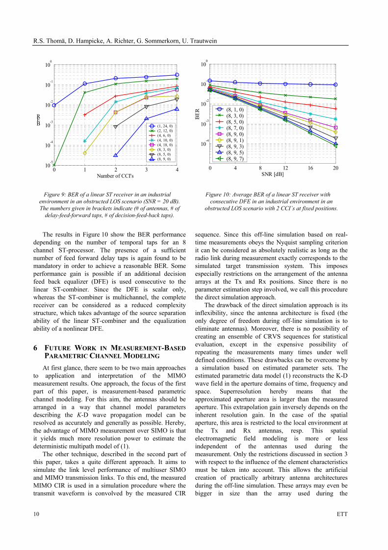
in an industrial environment based on real-time CIR measurements has been reported. The simulation scenario is given in Figure 8 and the corresponding channel impulse response statistics have been analyzed in [15]. The simulation results in Figure 9 and Figure 10 show uncoded bit error rates (BER's) for a variable number of co-channel interferers (CCI) and different complexity of the fractionally-spaced ST-processor with perfect power control simulated for the multiple users. Both figures impressively demonstrate how the performance of a ST processor for equalization and co-channel interference reduction depends on its complexity.
Figure 9 indicates the performance degradation with respect to an increasing number of CCI's. Obviously, reasonable BER’s can only be reached if the number of antennas is at least approximately two times higher than the number of CCI's. It should be noted, however, that the number of incoming waves is still much higher than the number of antennas, due to the "multipath richness" of the environment. The angular spread was on the order of 60 degrees azimuth. On the other hand, a minimum number of feed forward delay taps is required in this case. Note that the BER performance of a ST processor completely breaks down if the number of antennas is smaller or equal to the number of CCI's, even in the case of a very high number of feed-forward delay taps. It was also observed that the ability of the linear ST-processor does not depend on the DOA separation between the user-of-interest and the CCI's. This is in strong contrast to the performance of simple beamforming in the angular space only. Therefore, joint space-time beamforming can be considered very effective for user separation, at least in the case of a radio environment showing strong multipath and high angular spread. It is even expected that high multipath complexity of the radio environment supports the ability of the ST-processor to suppress CCI.
Multiuser SIMO radio environment
Linear ST combiner complexity: # of antennas x # of delay taps
DFE complexity: # of feed back taps
RLS weight adaption AWGN position
Tx1
Tx2
Tx3
Figure 8: Principle of Multiuser SIMO measurements and simulation
R.S. Thomä, D. Hampicke, A. Richter, G. Sommerkorn, U. Trautwein
10 ETT
0 1 2 3 410
-5
10-4
10-3
10-2
10-1
100
Number of CCI's
BER
(1, 24, 0)(2, 12, 0)(4, 6, 0) (4, 10, 0)(4, 18, 0)(8, 3, 0) (8, 5, 0) (8, 9, 0)
0 4 8 12 16 20
10-4
10-3
10-2
10-1
100
SNR [dB]
BER
(8, 1, 0)(8, 3, 0)(8, 5, 0)(8, 7, 0)(8, 9, 0)(8, 9, 1)(8, 9, 3)(8, 9, 5)(8, 9, 7)
Figure 9: BER of a linear ST receiver in an industrial environment in an obstructed LOS scenario (SNR = 20 dB). The numbers given in brackets indicate (# of antennas, # of
delay-feed-forward taps, # of decision-feed-back taps).
Figure 10: Average BER of a linear ST receiver with consecutive DFE in an industrial environment in an
obstructed LOS scenario with 2 CCI´s at fixed positions.
The results in Figure 10 show the BER performance depending on the number of temporal taps for an 8 channel ST-processor. The presence of a sufficient number of feed forward delay taps is again found to be mandatory in order to achieve a reasonable BER. Some performance gain is possible if an additional decision feed back equalizer (DFE) is used consecutive to the linear ST-combiner. Since the DFE is scalar only, whereas the ST-combiner is multichannel, the complete receiver can be considered as a reduced complexity structure, which takes advantage of the source separation ability of the linear ST-combiner and the equalization ability of a nonlinear DFE.
6 FUTURE WORK IN MEASUREMENT-BASED PARAMETRIC CHANNEL MODELING
At first glance, there seem to be two main approaches to application and interpretation of the MIMO measurement results. One approach, the focus of the first part of this paper, is measurement-based parametric channel modeling. For this aim, the antennas should be arranged in a way that channel model parameters describing the K-D wave propagation model can be resolved as accurately and generally as possible. Hereby, the advantage of MIMO measurement over SIMO is that it yields much more resolution power to estimate the deterministic multipath model of (1).
The other technique, described in the second part of this paper, takes a quite different approach. It aims to simulate the link level performance of multiuser SIMO and MIMO transmission links. To this end, the measured MIMO CIR is used in a simulation procedure where the transmit waveform is convolved by the measured CIR
sequence. Since this off-line simulation based on real-time measurements obeys the Nyquist sampling criterion it can be considered as absolutely realistic as long as the radio link during measurement exactly corresponds to the simulated target transmission system. This imposes especially restrictions on the arrangement of the antenna arrays at the Tx and Rx positions. Since there is no parameter estimation step involved, we call this procedure the direct simulation approach.
The drawback of the direct simulation approach is its inflexibility, since the antenna architecture is fixed (the only degree of freedom during off-line simulation is to eliminate antennas). Moreover, there is no possibility of creating an ensemble of CRVS sequences for statistical evaluation, except in the expensive possibility of repeating the measurements many times under well defined conditions. These drawbacks can be overcome by a simulation based on estimated parameter sets. The estimated parametric data model (1) reconstructs the K-D wave field in the aperture domains of time, frequency and space. Superresolution hereby means that the approximated aperture area is larger than the measured aperture. This extrapolation gain inversely depends on the inherent resolution gain. In the case of the spatial aperture, this area is restricted to the local environment at the Tx and Rx antennas, resp. This spatial electromagnetic field modeling is more or less independent of the antennas used during the measurement. Only the restrictions discussed in section 3 with respect to the influence of the element characteristics must be taken into account. This allows the artificial creation of practically arbitrary antenna architectures during the off-line simulation. These arrays may even be bigger in size than the array used during the

MIMO Vector Channel Sounder Measurement for Smart Antennas System Evaluation
11
measurement. Moreover, statistic ensembles of CRVS records can be created artificially. Remembering that the carrier wavelength is much smaller than the extrapolated array dimension, we can introduce some "virtual MS movement" superimposed on the MS trajectory covered during recording the measured data. If we further consider that the resolution of the transmission modem to be simulated is typically much less than the resolution capability of the channel sounder (in terms of the number of dimensions as well as of the measurement aperture size, e.g. bandwidth), this gives us even more power for statistical simulation. Reduced resolution of the target simulation system requires combining paths resolved in the model. This would result in a very realistic reproduction of small scale fading which is typical for low resolution receivers. First applications of this Monte-Carlo-like simulation based on hybrid measurement have been given in [23], [24]. It is worthwhile to compare the proposed channel simulation approach to the measurement-based SIMO channel model described in [26]. Because of the missing two-sided resolution, this model must still contain random tap weights, since local scattering around the MS cannot be resolved. This completely changes with MIMO measurements, since now the DOD of the waves at the MS are resolved. An extensive quantitative evaluation of the proposed deterministic modeling approach with a vast amount of measured data is still in progress.
7 CONCLUSIONS The well known sequential SIMO vector radio
channel sounder principle can be extended to MIMO measurements. The advantages are enhanced parameter resolution and additional direction of departure estimation. Whereas the antenna array multiplexing principle can easily be extended from SIMO to MIMO, the proper design and calibration of the antenna arrays needs highest attention. The measured MIMO channel results can be applied for precise reconstruction of the K-D EM wave propagation model independent of the antenna used during the measurement. This can form the key for measurement-based parametric channel modeling. Moreover, realistic measurement-based simulation of adaptive space-time processors in a multiuser SIMO environment has been reported. The results clearly show the BER performance in a real radio environment. This offers innovative potential for realistic simulation and optimization of MIMO space-time modems, which are considered very promising for capacity enhancement in future 4G mobile radio systems.
ACKNOWLEDGMENT The authors wish to thank MEDAV GmbH for the
cooperation in designing the RUSK MIMO vector radio channel sounder, R. Klukas (IRK Dresden) and Prof. Wiesbeck (University of Karlsruhe) for support in antenna design and Prof. U. Martin (Fachhochschule Mannheim) for valuable discussions.
Manuscript received on …
REFERENCES
[1] G.J. Foschini, M.J. Gans. On Limits of Wireless Communications in a Fading Environment when Using Multiple Antennas. Wireless Personal Communications, Vol. 6, pages 311-355, 1998.
[2] A. Paulraj, C.B. Papadias. Space-time processing for wireless communications. IEEE Signal Processing Magazine, Vol. 14, No. 5, pages 49-83, November 1997.
[3] R.B. Ertel, P. Cardieri, K.W. Sowerby, T.S. Rappaport, J.H. Reed. Overview of Spatial Channel Models for Antenna Array Communication Systems. IEEE Personal Communications, Vol. 5, No. 1, pages 10-22, 1998.
[4] K. Schwarz, U. Martin, H.W. Schüßler. Devices for Propagation Measurement in Mobile Radio Channels. Proc. of the 4th IEEE Int. Symp. on Personal Indoor and Mobile Radio Communications, PIMRC'93, Yokohama, Japan, pages 387-391, 1993.
[5] R.S. Thomä, D. Hampicke, A. Richter, G. Sommerkorn, A. Schneider, U. Trautwein, W. Wirnitzer. Identification of Time-Variant Directional Mobile Radio Channels. IEEE Transactions on Instrumentation and Measurement, Vol. 49, No. 2, pages 357-364, 2000.
[6] U. Martin. Spatio-Temporal Radio Channel Characteristics in Urban Macrocells. IEE Proceedings on Radar, Sonar and Navigation. Vol. 145, No. 1, pages 42-49, 1998.
[7] D.C. Cox. Delay Doppler Characteristics of Multipath Propagation at 910 MHz in a Suburban Mobile Radio Environment. IEEE Transactions on Antennas and Propagation, Vol. AP 20, No. 5, pages 625-635, 1972.
[8] U. Trautwein, K. Blau, D. Brückner, F. Herrmann, A. Richter, G. Sommerkorn, R.S. Thomä. Radio Channel Measurement for Realistic Simulation of Adaptive Antenna Arrays. The 2nd European Personal Mobile Communications Conference, EPMCC '97, Bonn, Germany, pages 491-498, 1997.
[9] H. Krim, M. Viberg. Two Decades of Array Signal Processing Research. IEEE Signal Processing Magazine. Vol. 13, No. 4, pages 67-94, 1996.
[10] T. Zwick. Die Modellierung von richtungsaufgelösten Mehrwegegebäudefunkkanälen durch markierte Poisson-Prozesse. Forschungsberichte aus dem Institut für
R.S. Thomä, D. Hampicke, A. Richter, G. Sommerkorn, U. Trautwein
12 ETT
Höchstfrequenztechnik und Elektronik der Universität Karlsruhe, Bd. 23, 2000.
[11] M. Steinbauer, A.F. Molisch, E. Bonek. The Double-Directional Mobile Radio Channel. IEEE Antennas and Propagation Magazine, accepted for publication.
[12] M. Haardt, J.A. Nossek. Unitary ESPRIT: How to Obtain Increased Estimation Accuracy With Reduced Computational Burden. IEEE Transactions on Signal Processing, Vol. 43, pages 1232-1242, 1995.
[13] M. Haardt. Efficient One-, Two-, and Multidimensional High-Resolution Array Signal Processing. Dr.-Ing. Thesis, TU München, Shaker Verlag 1997.
[14] A. Richter, R.S. Thomä. CUBA-ESPRIT for Angle Estimation with Circular Uniform Beam Arrays. Proceedings of the Millenium Conference on Antennas and Propagation, AP2000, Davos, CH, 2000.
[15] D. Hampicke, A. Richter, A. Schneider, G. Sommerkorn, R.S. Thomä, U. Trautwein. Characterization of the Directional Mobile Radio Channel in Industrial Scenarios, Based on Wide-Band Propagation Measurements. Proc. IEEE Vehicular Technology Conference (VTC 1999-Fall), Amsterdam, Vol. 4, pages 2258-2262, 1999.
[16] G. Sommerkorn, D. Hampicke, R. Klukas, A. Richter, A. Schneider, R.S. Thomä. Reduction of DoA Estimation Errors Caused by Antenna Array Imperfections. Proceedings 29th European Microwave Conference, Munich, Vol. 2, pages 287-290, 1999.
[17] G. Sommerkorn, D. Hampicke, A. Richter, R. Thomä. Measurement and Modeling Error Influence to Antenna Array Calibration and its Affect to ESPRIT-Based DOA-Estimation. Proceedings of the Millennium Conference on Antennas and Propagation, AP 2000, Davos, CH, 2000.
[18] G. Sommerkorn, D. Hampicke, R. Klukas, A. Richter, A. Schneider, R.S. Thomä. Uniform Rectangular Antenna Array Calibration Issues for 2-D ESPRIT Application. 4th European Personal Mobile Communications Conference EPMCC 2001, Vienna, Austria, 2001.
[19] U. Trautwein, D. Hampicke, G. Sommerkorn, R.S. Thomä. Performance of Space-Time Processing for ISI- and CCI Suppression in Industrial Scenarios. Proceedings IEEE Vehicular Technology Conference, VTC2000-Spring, Tokyo, JP, 2000.
[20] A. Richter, D. Hampicke, G. Sommerkorn, R.S. Thomä. Joint Estimation of DoD, Time-Delay, and DoA for High Resolution Channel Sounding. Proceedings IEEE Vehicular Technology Conference, VTC2000-Spring, Tokyo, JP, 2000.
[21] T. Zwick, D. Hampicke, J. Maurer, A. Richter, G. Sommerkorn, R. Thomä, W. Wiesbeck. Results of Double-Directional Channel Sounding Measurements. Proceedings IEEE Vehicular Technology Conference, VTC2000-Spring, Tokyo, JP, 2000.
[22] M. Steinbauer, D. Hampicke, G. Sommerkorn, A. Schneider, A.F. Molisch R. Thomä, E. Bonek. Array Measurement of the Double-Directional Mobile Radio Channel. Proceedings IEEE Vehicular Technology Conference, VTC2000-Spring, Tokyo, JP, 2000.
[23] M. Steinbauer, A.F. Molisch A. Burr, R. Thomä. MIMO Channel Capacity Based Measurement Results. Proceedings ECWT 2000, Paris, 2000.
[24] A.F. Molisch, M. Steinbauer, E. Bonek, R.S. Thomä. Measurement of the Capacity of MIMO Systems in Frequency-Selective Channels. Proceedings IEEE Vehicular Technology Conference, VTC2001-Spring, Rhodos, Greece, 2001.
[25] A. Richter, D. Hampicke, G. Sommerkorn, R.S. Thomä. MIMO Measurement and Joint Parameter Estimation of Mobile Radio Channels. Proceedings IEEE Vehicular Technology Conference, VTC2001-Spring, Rhodos, Greece, 2001.
[26] U. Martin. Statistical Mobile Radio Channel Simulator for Multiple-Antenna Reception. IEICE 1996 International Symposium on Antennas and Propagation, Chiba, JP, pages 217-220, 1996.


![Printed Multi-Band MIMO Antenna Systems and Their ... · the diversity performance of the MIMO antenna system [3]. A ... Multiple-input-multiple-output (MIMO) antenna systems are](https://img.pdfslide.us/doc/110x75/601832972ff2e95336029d17/printed-multi-band-mimo-antenna-systems-and-their-the-diversity-performance.jpg)