Embed Size (px)
Citation preview
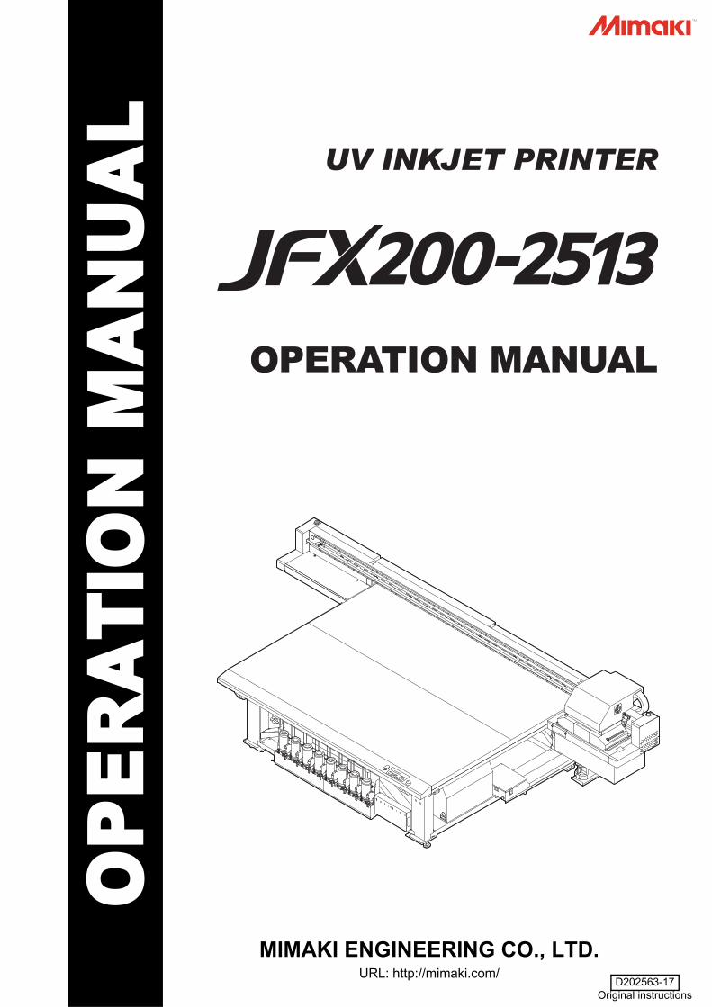
MIMAKI ENGINEERING CO., LTD.URL: http://mimaki.com/
D202563-17Original instructions
i
CAUTION ............................................................................. vDISCLAIMER OF WARRANTY ....................................... vRequests ......................................................................... vFCC Statement (USA) ..................................................... vInterference to televisions and radios .............................. vRestriction in use .............................................................vi
Foreword ............................................................................ viiAbout usable ink .............................................................viiOn This Operation manual .............................................vii
Safety Precautions .............................................................viiiSymbols ......................................................................... viii
Warning labels ................................................................... xiv
Chapter 1 Before UseAbout installing this machine .............................................1-2
Where to Install This Machine .......................................... 1-2Working Environmental Temperature ............................... 1-2About fixing machine ........................................................ 1-3Moving This Machine ........................................................ 1-3
Names of Parts and Functions ..........................................1-4Front Side of the Machine ................................................ 1-4Rear Side and Right Side of the Machine ........................ 1-4Operation Panel ................................................................ 1-5Carriage ............................................................................ 1-6Capping station ................................................................. 1-6EMERGENCY SWITCH ................................................... 1-6
Connecting Cables ............................................................1-7Connecting USB2.0 Interface Cable ................................. 1-7Connecting Power Supply Cable ...................................... 1-8
Setting ink bottles ..............................................................1-9Caution in handling of ink bottles .................................... 1-15
Media ...............................................................................1-16Usable sizes of media .................................................... 1-16Caution in handling of medias ........................................ 1-16
Chapter 2 Basic OperationsWorkflow ............................................................................2-2Turning the Power ON/OFF ..............................................2-3
Turning the Power ON ...................................................... 2-3Turning the Power OFF .................................................... 2-4
Setting a Media .................................................................2-5Setting the Media .............................................................. 2-5
Move the irradiation position of the UV lamp .....................2-8Test Printing ....................................................................2-13
Test Printing ................................................................... 2-14
TABLE OF CONTENS
ii
Head Cleaning ................................................................ 2-15About head cleaning .......................................................2-15Perform head cleaning depending on the test printing result ...............................................................................2-15
Printing Data ................................................................... 2-16Starting a Printing Operation ..........................................2-16Stopping a printing operation halfway .............................2-17Deleting Received Data (Data Clear) .............................2-17Move the Y-bar ...............................................................2-18
Chapter 3 Extended FunctionsChanging origin ................................................................. 3-2
Changing origin with JOG keys ........................................3-2Changing origin with FUNCTION menu ............................3-3
Registering the thickness of the media ............................. 3-4Register the thickness of the media manually ..................3-4Adjust head gap with the or keys ....................................3-4Measuring the thickness of the media automatically ........3-5
Registering Head gap value ............................................. 3-6List of Functions ................................................................ 3-7Correct the ink drop position for bidirectional printing ....... 3-8Setting Logical Seek ....................................................... 3-10Setting UV mode ............................................................. 3-11Perform setting to reduce stripes between passes ......... 3-12
What is the MAPS Function? ..........................................3-12Setting MAPS1 Function .................................................3-12Setting MAPS2 Function (4 color) ..................................3-13Setting MAPS2 Function (4 color + special color ink) .....3-14
Setting Work Change ...................................................... 3-17Setting Ionizer ................................................................. 3-18Setting Auto Cleaning ..................................................... 3-19Setting nozzle face cleaning time ................................... 3-20Other Settings ................................................................. 3-21Machine Settings ............................................................ 3-22
Setting a AUTO Power-off ..............................................3-22Setting Time ....................................................................3-23Setting Units ...................................................................3-24Setting a KEY BUZZER ..................................................3-25Setting a LANGUAGE .....................................................3-26
Initializing the Settings .................................................... 3-27Confirming Machine Information ..................................... 3-28
Check the using status of the machine ...........................3-28Check the machine version information ..........................3-29Displaying the Information of this machine .....................3-30
iii
Chapter 4 MaintenanceMaintenance ......................................................................4-2
Precautions for Maintenance ............................................ 4-2About Cleaning liquid ........................................................ 4-2Maintenance of frame component .................................... 4-2MBIS Maintenance ........................................................... 4-3Cleaning the LM guide ...................................................... 4-3
Maintaining the Capping Station .......................................4-4Cleaning the Wiper and Cap ............................................ 4-4Cleaning the around station .............................................. 4-7
Cleaning the Head and the Area around It ........................4-8Washing the Ink Discharge Passage (DISWAY WASH) ........................................................... 4-10When the Machine Is Not Used for a Long Time (CUSTODY WASH) ........................................................ 4-11
When Nozzle Clogging Cannot Be Solved ......................4-14Filling with ink from the sub tank to the head ................. 4-14Washing of Head nozzle ................................................. 4-15If nozzle missing due to color mixture of ink or aeration . 4-17Alternative nozzles for printing, when nozzles missing can not be improved ...............................................................................4-20
Automatic Maintenance Function ....................................4-25Setting the Refreshing Intervals ..................................... 4-25Setting the Cleaning Intervals ......................................... 4-26
Replacing consumables ..................................................4-27Replacing the wiper ........................................................ 4-27If a Waste Ink Tank Confirmation Message Appears ..... 4-28Replacing the waste ink tank before the waste ink tank confirmation message is displayed (1) ........................... 4-31Replacing the waste ink tank before the waste ink tank confirmation message is displayed (2) ........................... 4-32
Refilling antifreeze mixed water ......................................4-33Refill cooling water ......................................................... 4-34
Exchange the flushing filter .............................................4-36If a Flushing Filter Exchange Message Appears ............ 4-36Replacing the flushing filter before the replacement message is displayed ..................................................... 4-37
Chapter 5 TroubleshootingTroubleshooting .................................................................5-2
Power does not turn on .................................................... 5-2The machine does not start printing ................................. 5-2Image quality is poor ........................................................ 5-3Nozzle is clogged ............................................................. 5-3Ink bottle warning appears ............................................... 5-4If a Message “SHAKE WHITE INK BOTLES” Appears .... 5-5If an error related to the sub tank occurs (Error 618 to 61b) ............................................................. 5-6If negative pressure abnormality occurs ........................... 5-7
iv
Warning / Error Messages ................................................ 5-9Warning messages ...........................................................5-9Error messages ..............................................................5-12
Chapter 6 AppendixSpecifications .................................................................... 6-2
Machine specifications ......................................................6-2Ink specifications ..............................................................6-3
Setting orders depending on ink type ............................... 6-4Setting orders of ink bottles ..............................................6-4
Sheet for inquiry ................................................................ 6-6Function Flowchart ........................................................... 6-8
v
CAUTIONDISCLAIMER OF WARRANTY
THIS LIMITED WARRANTY OF MIMAKI SHALL BE THE SOLE AND EXCLUSIVE WARRANTY AND IS INLIEU OF ALL OTHER WARRANTIES, EXPRESS OR IMPLIED, INCLUDING, BUT NOT LIMITED TO, ANYIMPLIED WARRANTY OF MERCHANTABILITY OR FITNESS, AND MIMAKI NEITHER ASSUMES NORAUTHORIZES DEALER TO ASSUME FOR IT ANY OTHER OBLIGATION OR LIABILITY OR MAKE ANYOTHER WARRANTY OR MAKE ANY OTHER WARRANTY IN CONNECTION WITH ANY PRODUCTWITHOUT MIMAKI’S PRIOR WRITTEN CONSENT.IN NO EVENT SHALL MIMAKI BE LIABLE FOR SPECIAL, INCIDENTAL OR CONSEQUENTIAL DAMAGESOR FOR LOSS OF PROFITS OF DEALER OR CUSTOMERS OF ANY PRODUCT.
Requests• This Operation manual has been carefully prepared for your easy understanding.
However, please do not hesitate to contact a distributor in your district or our office if you have any inquiry.• Description contained in this Operation manual are subject to change without notice for improvement.
FCC Statement (USA)This equipment has been tested and found to comply with the limits for a Class A digital device, pursuant toPart 15 of the FCC Rules. These limits are designed to provide reasonable protection against harmfulinterference when the equipment is operated in a commercial environment. This equipment generates, usesand can radiate radio frequency energy and, if not installed and used in accordance with the Operation manual,may cause harmful interference to radio communications.Operation of this equipment in a residential area is likely to cause harmful interference in which case the userwill be required to correct the interference at his own expense.In the case where MIMAKI-recommended cable is not used for connection of this device, limits provided byFCC rules can be exceeded.To prevent this, use of MIMAKI-recommended cable is essential for the connection of this printer.
Interference to televisions and radiosThe product described in this manual generates high frequency when operating.The product can interfere with radios and televisions if set up or commissioned under improper conditions.The product is not guaranteed against any damage to specific-purpose radio and televisions.The product’s interference with your radio or television will be checked by turning on/off the power button of theproduct.In the event that the product is the cause of interference, try to eliminate it by taking one of the followingcorrective measures or taking some of them in combination.
• Change the orientation of the antenna of the television set or radio to find a position without reception difficulty.• Separate the television set or radio from this product.• Plug the power cord of this product into an outlet which is isolated from power circuits connected to the
television set or radio.
CAUTION
vi
1
2
3
4
5
6
Restriction in useRestriction in useThis machine features high-speed parts, hot parts and UV irradiating parts which need very careful attention. Useof this machine is limited to the user who understands the risks of inappropriate use completely.
Restriction for userThe user of this machine shall get proper training. Limit to the user those who got proper training to operate thismachine.
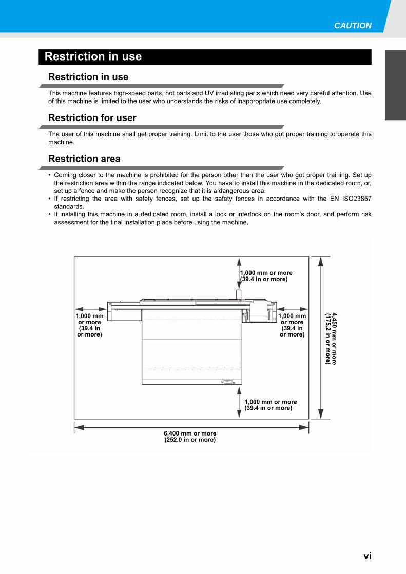
Restriction area• Coming closer to the machine is prohibited for the person other than the user who got proper training. Set up
the restriction area within the range indicated below. You have to install this machine in the dedicated room, or,set up a fence and make the person recognize that it is a dangerous area.
• If restricting the area with safety fences, set up the safety fences in accordance with the EN ISO23857standards.
• If installing this machine in a dedicated room, install a lock or interlock on the room’s door, and perform riskassessment for the final installation place before using the machine.
6,400 mm or more(252.0 in or more)
1,000 mmor more(39.4 in
or more)
1,000 mmor more(39.4 in
or more)
1,000 mm or more(39.4 in or more)
1,000 mm or more(39.4 in or more)
4,450 mm
or more
(175.2 in or more)
vii
ForewordCongratulations on your purchase of MIMAKI color ink jet printer "JFX200 Series" .“JFX200 Series” is a UV inkjet printer that can print with UV ink realizing high speed and high image quality.
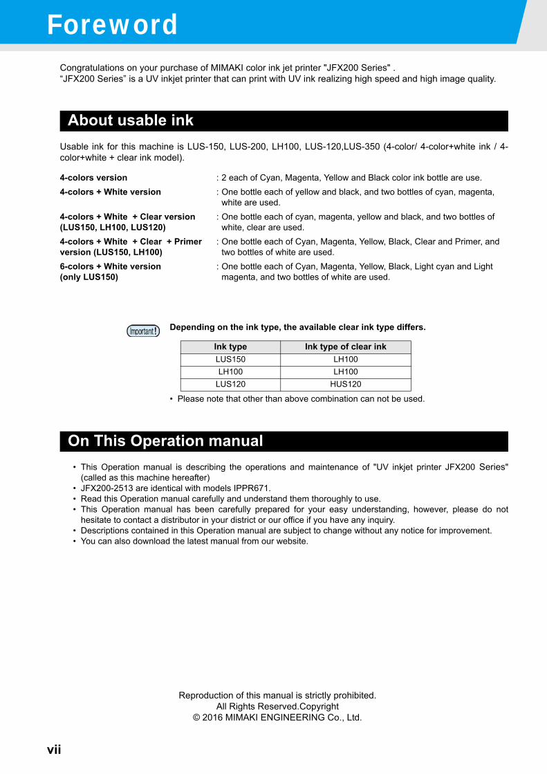
About usable inkUsable ink for this machine is LUS-150, LUS-200, LH100, LUS-120,LUS-350 (4-color/ 4-color+white ink / 4-color+white + clear ink model).
On This Operation manual• This Operation manual is describing the operations and maintenance of "UV inkjet printer JFX200 Series"
(called as this machine hereafter)• JFX200-2513 are identical with models IPPR671.• Read this Operation manual carefully and understand them thoroughly to use.• This Operation manual has been carefully prepared for your easy understanding, however, please do not
hesitate to contact a distributor in your district or our office if you have any inquiry.• Descriptions contained in this Operation manual are subject to change without any notice for improvement.• You can also download the latest manual from our website.
Reproduction of this manual is strictly prohibited.All Rights Reserved.Copyright
© 2016 MIMAKI ENGINEERING Co., Ltd.
4-colors version : 2 each of Cyan, Magenta, Yellow and Black color ink bottle are use.4-colors + White version : One bottle each of yellow and black, and two bottles of cyan, magenta,
white are used.4-colors + White + Clear version(LUS150, LH100, LUS120)
: One bottle each of cyan, magenta, yellow and black, and two bottles of white, clear are used.
4-colors + White + Clear + Primer version (LUS150, LH100)
: One bottle each of Cyan, Magenta, Yellow, Black, Clear and Primer, and two bottles of white are used.
6-colors + White version(only LUS150)
: One bottle each of Cyan, Magenta, Yellow, Black, Light cyan and Light magenta, and two bottles of white are used.
Depending on the ink type, the available clear ink type differs.
• Please note that other than above combination can not be used.
Ink type Ink type of clear inkLUS150 LH100LH100 LH100
LUS120 HUS120
viii
1
2
3
4
5
6
Safety PrecautionsSymbols
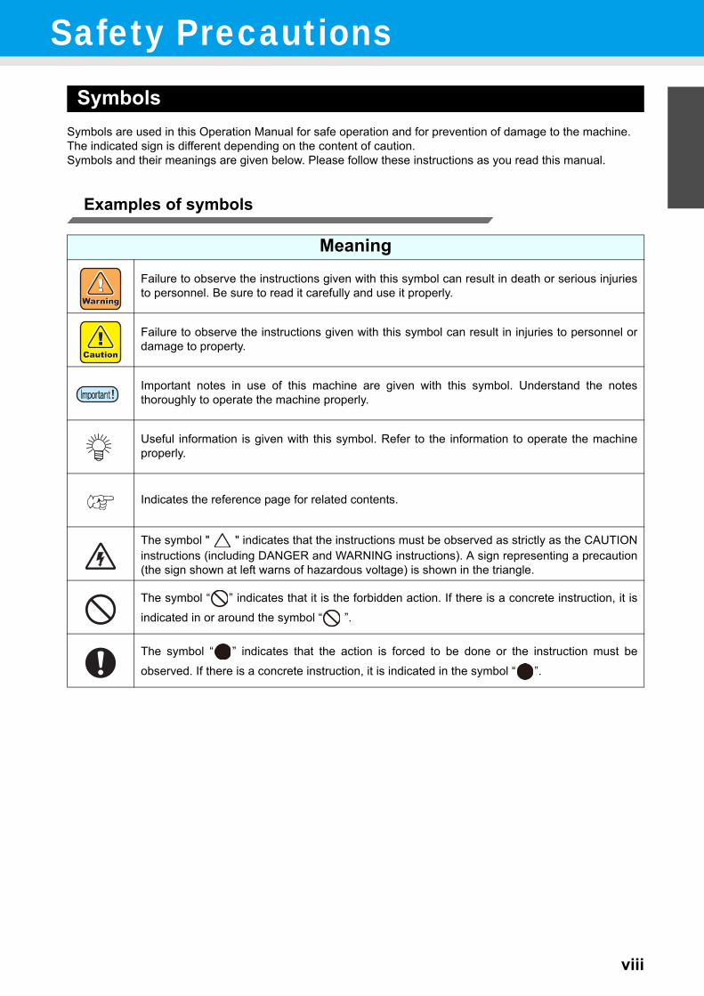
Symbols are used in this Operation Manual for safe operation and for prevention of damage to the machine.The indicated sign is different depending on the content of caution.Symbols and their meanings are given below. Please follow these instructions as you read this manual.
Examples of symbols
MeaningFailure to observe the instructions given with this symbol can result in death or serious injuriesto personnel. Be sure to read it carefully and use it properly.
Failure to observe the instructions given with this symbol can result in injuries to personnel ordamage to property.
Important notes in use of this machine are given with this symbol. Understand the notesthoroughly to operate the machine properly.
Useful information is given with this symbol. Refer to the information to operate the machineproperly.
Indicates the reference page for related contents.
The symbol " " indicates that the instructions must be observed as strictly as the CAUTIONinstructions (including DANGER and WARNING instructions). A sign representing a precaution(the sign shown at left warns of hazardous voltage) is shown in the triangle.
The symbol “ ” indicates that it is the forbidden action. If there is a concrete instruction, it isindicated in or around the symbol “ ”.
The symbol “ ” indicates that the action is forced to be done or the instruction must beobserved. If there is a concrete instruction, it is indicated in the symbol “ ”.
ix
Warning for Use
WARNING• Be sure to setup the appropriate air-moving system in case of using the device in a closed room or a room with
bad ventilation.
• The ink used for this device falls into the category of UN No.3082 and UN Class 9. Since the ink is flammable,never use fire when using the device.
• When cleaning the ink station and head, be sure to wear the supplied goggle and gloves since you may get inkor washing liquid in your eyes.
• If anyone drinks ink or washing liquid in mistake, get the person to vomit and see a doctor immediately.Do notallow him or her drink vomit.Then, refer SDS about the inquiry.
• If you absorb a lot of vapor and feel bad, immediately move to a location where fresh air is present and thenkeep yourself warm and quiet.Then, consult a doctor as soon as possible.
• Discard the waste ink according to the local regulations of the area this unit is used.• Prevent any leaks into sewage or natural water systems.• In case of ink leakage, please turn off the main power, unplug the power cable and call for service to our
service or dealer.Do not disassemble or remodel the device Handling of ink bottles
• Never disassemble or remodel the main unit ofthe printer and the ink cartridge.Disassembling/remodeling any of them will result in electricshocks or breakdown of the device.
• Some of the ingredients (UV Curing initiator)have toxic consequences to aquatic life.Avoidleak into water system or sewage containingwater.
• Store ink bottles and waste ink tank in a placethat is out of the reach of children.
• If ink settles on the skin or clothes, immediatelywash it off with detergent or water.If you get inkin your eyes, immediately wash your eyes with alot of clean water for at least 15 minutes. In thiscase, also wash the backside of eyelids to rinseink away completely. Then, consult a doctor assoon as possible.
Do not use the device in damp places• Avoid damp environments when putting the
device into service. Do not splash water onto thedevice.Highhumidity or water will give rise to fire,electric shocks or breakdown of the device.
Abnormal event occurs• If the device is used under an abnormal
condition where the device produces smoke orunpleasant smell, fire or electric shocks canresult.Be sure to turn off the power switchimmediately and detach the plug from thereceptacle.Check first to be sure that the deviceno longer produces smoke, and contact adistributor in your district for repair.
• Never repair your device by yourself since it isvery dangerous for you to do so.
Grounding work• Grounding work is necessary to prevent
electrocution accidents when installing an outlet.• Carry out the grounding work.
Handling of the power cable• Use a power cable attached to this unit.• Take care not to damage, break or work on the
power cable.If a heavy matter is placed on thepower cable, heated or drawn, the power cablecan break to cause fire or electric shocks.
Wearing protective devices• When cleaning parts such as the head, wiper, or
cap, which may scatter ink and washing liquid,be sure to wear safety glasses and gloves, or inkand washing liquid might enter your eyes or inkand washing liquid put on your hands mightmake your hands rough.
Do not ride on the table• There is a possibility that the board accuracy
falls. Please never ride on top of the table.
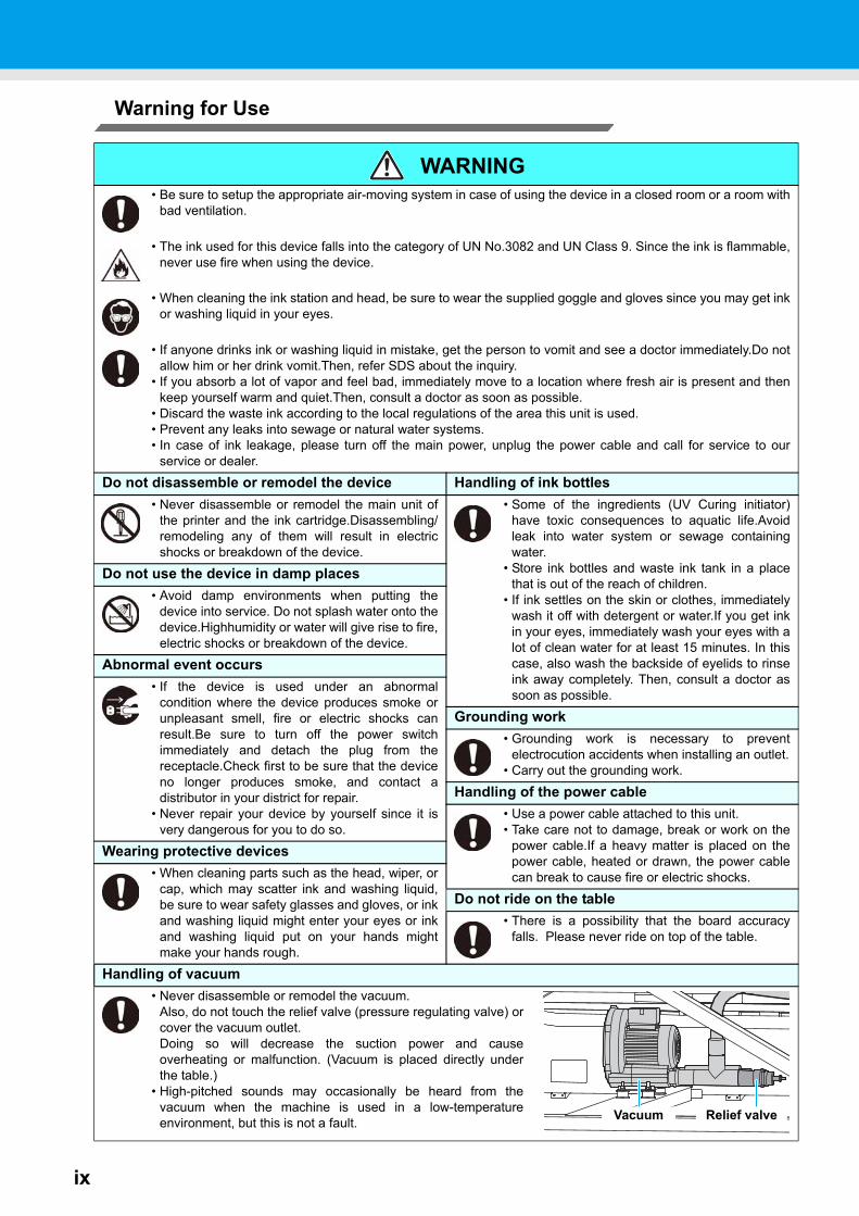
Handling of vacuum• Never disassemble or remodel the vacuum.
Also, do not touch the relief valve (pressure regulating valve) orcover the vacuum outlet.Doing so will decrease the suction power and causeoverheating or malfunction. (Vacuum is placed directly underthe table.)
• High-pitched sounds may occasionally be heard from thevacuum when the machine is used in a low-temperatureenvironment, but this is not a fault. Relief valveVacuum
Safety Precautions
x
1
2
3
4
5
6
WARNINGPower supply and voltage
• This unit contains parts applied high voltage.Carrying out electrical work by those unauthorized for that work isprohibited.
• Use it with the displayed power supply specifications. The power-supply voltage of this machine shall besingle-phase 200 to 240 Vac 15 A and less. (You cannot use this machine in the 100V system.)
• Be sure to always disconnect the power plug when performing maintenance in order to prevent electricalshock. Depending on the device, one minute might be required for condenser discharging time. Be sure toalways wait five minutes or more after disconnecting the power plug before performing any work.
• Be sure to carry out grounding work to prevent electrical shock.• The main power circuit breaker should be set ON only by personnel with sufficient knowledge about operations
of this unit.• Do not touch the LED UV unit on or right after the lamp off with bare hands to avoid from burn injury.
Handling the Anti-freezing liquid• Use the exclusive Anti-freezing liquid by Mimaki ,or the machine may be damaged.• If the Anti-freezing liquid or Cooling tank water gets on the skin or clothes, immediately wash it off with soap.
If you get the Anti-freezing liquid or Cooling tank water in your eyes, immediately wash your eyes with a lot ofclean water. Then, consult a doctor as soon as possible.If high temperature Anti-freezing liquid or Cooling tank water getson the skin, immediately wash it off with soap and cool with iced water. Then, consult a doctor as soon aspossible.
• Before using the Anti-freezing liquid, be sure to read the Safety Data Sheet (SDS).• If you swallowed the Anti-freezing liquid or mixed soft water with antifreezing liquid accidentally, try to get to
vomit, and then consult a doctor as soon as possible.• When unused the Anti-freezing liquid or used Cooling tank water should discard as followings, Incinerating the fluid which is absorbed to the sawdust or waste cloth. Entrust them to an industrial waste disposal contractor, clarifying their contents.
• Avoid ignition such as static electricity and impact spark.• Be sure to wear goggles and gloves for handling the Anti-freezing liquid.
Handling of LED UV unit• Do not use the LED UV in an ambience with a possibility of catching fire (gasoline, combustible gas spray,
thinner, lacquer, powder dust, etc.). In addition, do not put paper or cloth near or on the LEDUV, or it maycause fire.or it may cause electrical shock.
• Never look at the LED UV being lit with your naked eyes,or it may cause pain in your eyes or visualimpairment.Be sure to wear safety glasses.
• Do not apply ultraviolet (UV) light directly to your skin,or it may cause irritation on your skin.• It is recommended to replace the LED UV unit within the rated life.
Disposition of this machine• When discarding this machine, request the treatment of it for an industrial waste disposal contractor.• Treat it properly in compliance with regulation in the local area.
xi
Precautions in Use
CAUTIONProtection against dust Periodic exchange parts
• It is strongly recommended to use the device ina room that is not dusty.
• When leaving the workshop after the workinghours, be sure to take off any media from the roll
• hanger.If any media is left on the roll hanger,dust can put on it.
• Store media in a bag.Wiping off dustaccumulated on a media will adversely affect themedia due to static electricity.
• Dust in the head will also cause drops of ink tofall abruptly down on the media during printing.Ifthis phenomenon takes place, be sure to cleanup the head. ( P.2-15)
• There are some parts which must be replacedby service men.You have to make a contractwith distributors or dealers for after-sale service.
Keep the machine flatly• Be sure to adjust the level foot to keep the
machine flatly.
Handling of maintenance liquid• Be sure to store the maintenance liquid in a cold
and dark place.Store the maintenance liquid in aplace that is out of the reach of children.
Warning labels Note on maintenance• This device is adhered with a warning label. Be
sure understand firmly the warnings given on thelabels.In the case where any of the warning labelhas become so soiled that the warning messageis illegible or has come off, purchase a new onefrom your local distributor or our office.
• When cleaning parts such as the head, wiper, orcap, make sure to wear the attached gloves.
Handling the Anti-freezing liquid Power supply• Be sure to store the Anti-freezing liquid in a cold
and dark place.• Store the Anti-freezing liquid in a place that is
out of the reach of children.
• Leave the breaker turned ON.• Do not turn off the main power switch on the
right side of this machine.
Handling of ink bottles• Use the JFX200 genuine ink. Remember that the user shall be filled for a repair to correct any damage
resulting from the use of ink other than the exclusive type.• The machine does not operate with any ink other than the JFX200 genuine ink.• Do not use the JFX200 genuine ink with other printers, as doing so may cause damage to such machines.• Do not refill ink other than the one specified by our company in the bottle. We are not responsible for any
defects caused by your using such an ink.• If the ink bottle is moved from a cold place to a warm place, leave it in the room temperature for three hours or
more before using it.• Open the ink bottle just before installing it in the machine. If it is opened and left for an extended period of time,
normal printing performance of the machine may not be ensured.• Make sure to store ink bottles in a cool and dark place.• Store ink bottles and waste ink tank in a place that is out of the reach of children.• Be sure to thoroughly consume the ink in the ink bottle, once it is opened, within three months. If an extended
period of time has passed away after opening the ink bottle, printing quality would be poor.• Neither pound the ink bottle nor shake it violently, as doing so can cause leakage of ink.• Do not touch or stain the contacts of the IC chip, as doing so may cause damage to the print circuit board.• Waste ink is equivalent to waste oil of industrial waste. Request an industrial waste disposal company for
disposal of waste ink.
Handling of media• Use media recommended by MIMAKI to ensure reliable, high-quality printing.• Pay attention to the expansion and contraction of the media.
Do not use media immediately after unpacking. The media can be affected by the room temperature andhumidity, and thus it may expand and contract. The media have to be left in the atmosphere in which they areto be used for 30 minutes or more after unpacked.
• Do not use curled media. The use of curled media can not only cause a media jam but also affect print quality. Straighten the sheet ofmedia, if significantly curled, before using it for printing. If a regular-sized coated sheet of media is rolled andstored, the coated side has to face outside.
Safety Precautions
xii
1
2
3
4
5
6
CAUTIONAbout UV light About hot parts
• A little UV light leaks from the LED UV unit. UVlight applied to your skin might causeinflammation and/or skin cancer.Though weakUV light might cause no inflammation, repeatedexposure to it may lead to chronicdisorders.Avoid applying UV light to your skinand eyes.
• The LED UV unit and the Post Cure Unitbecome very hot. When carrying outmaintenance, wait until the temperature hasbeen sufficiently lowered after the lamp is turnedOFF.
• Do not touch the parts with the caution labelplaced and their vicinity, or burn injury mayoccur.• Possible damage to your eyes due to ultraviolet
is acute disorder (feeling like something is inyour eye, pain and flow of tears) and chronicdisorder (cataract etc.). When using this device,take protective measures such as gloves, long-sleeve cloth, light-resistant mask, attached light-resistant glasses, etc.
• When it is unavoidable to touch hot parts, besure to wear heat-insulating gloves to protectyour hands.
Notes on LED UV unit About cleaning• When handling the LED UV or the silica glass on
the bottom of the irradiation device, be sure towear the gloves attached and never touch themwith bare hands, or the UV ink curing level issignificantly lowered. If the LED UV or silicaglass is contaminated, wipe it with clean gauzemoistened with alcohol.(Do not use alcohol forcleaning the exterior cover, or the paint will peeloff.)
• After using the unit long time, foreign materialsand dust may be gathered on the conductiveand insulating parts, causing electricleakage.Periodically clean such parts.
• For cleaning, do not use compressed airbecause it scatters foreign materials and dust,which may cause malfunctions when put insidethe conductive parts.Be sure to use vacuumcleaner for cleaning of foreign materials anddust.
• Do not use the unit in a place where there is apossibility of being wet, or electrical leakage mayoccur.
• Electrical leakage, if it should occur, may lead toelectrical shock of personnel or fire.
• In order to prevent accidents from occurring, besure to carry out periodic inspections andreplacement of timechange components.
• Never use those UV devices other than thoserecommended by Mimaki. We would take noresponsibility for any troubles caused throughthe use of a UV devices not recommended byMimaki.
About firing and smoking• Touching hot parts such as the LED UV unit with combustible materials may cause firing and/or smoking.
Leaving combustible materials under the UV LED unit for a couple minutes may also cause firing and/orsmoking.
• After the unit is used long time, foreign materials or dust gathered on the stabilizer or other parts may causeelectrical leakage or insulation deterioration may cause firing and/or smoking.Periodically clean the parts andmeasure the insulation resistance, replacing deteriorated parts, if any.
• After the unit is used long time, screws, etc. on the conductive parts may be loosened, causing firing and/orsmoking.Periodically tighten such screws.
• Because this unit is not of explosion proof type,do not use it in an ambience with hazardous materials, or apossibility of explosion may arise.
• If abnormalities of the unit such as a strange odor, a smoking or a spark burn are found, turn the power off andcall Mimaki immediately.
Safety Precautions
xiii
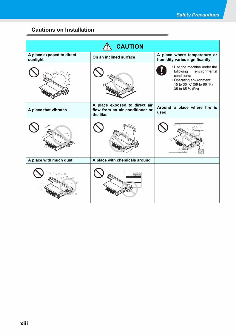
Cautions on Installation
CAUTIONA place exposed to direct sunlight On an inclined surface A place where temperature or
humidity varies significantly
• Use the machine under thefollowing environmentalconditions:
• Operating environment:15 to 30 °C (59 to 86 °F)35 to 65 % (Rh)
A place that vibratesA place exposed to direct airflow from an air conditioner orthe like.
Around a place where fire isused
A place with much dust A place with chemicals around
xiv
1
2
3
4
5
6
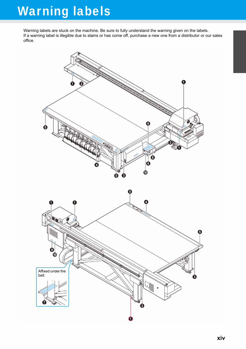
Warning labelsWarning labels are stuck on the machine. Be sure to fully understand the warning given on the labels.If a warning label is illegible due to stains or has come off, purchase a new one from a distributor or our sales office.
Affixed under the belt.
Warning labels
xv
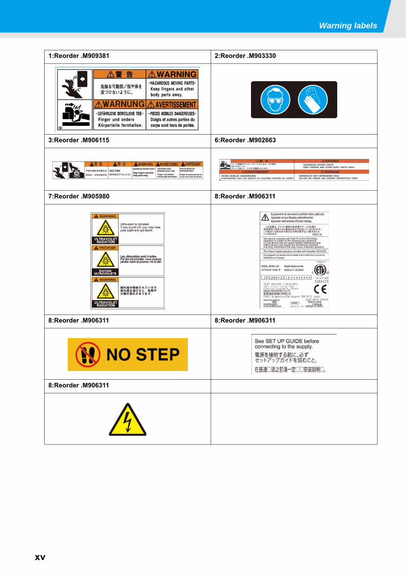
1:Reorder .M909381 2:Reorder .M903330
3:Reorder .M906115 6:Reorder .M902663
7:Reorder .M905980 8:Reorder .M906311
8:Reorder .M906311 8:Reorder .M906311
8:Reorder .M906311
This chapter
describes the items required to understand before use, such as the name of each part ofthe machine or the installation procedures.
About installing this machine ........................1-2Where to Install This Machine ..................... 1-2Working Environmental Temperature ......... 1-2About fixing machine ................................... 1-3Moving This Machine .................................. 1-3
Names of Parts and Functions ......................1-4Front Side of the Machine ........................... 1-4Rear Side and Right Side of the Machine ... 1-4Operation Panel .......................................... 1-5Carriage ...................................................... 1-6Capping station ........................................... 1-6EMERGENCY SWITCH .............................. 1-6
Connecting Cables ........................................1-7Connecting USB2.0 Interface Cable ............1-7Connecting Power Supply Cable .................1-8
Setting ink bottles ..........................................1-9Caution in handling of ink bottles ...............1-15
Media ..........................................................1-16Usable sizes of media ................................1-16Caution in handling of medias ...................1-16
Chapter 1Before Use
1-2
About installing this machineWhere to Install This Machine
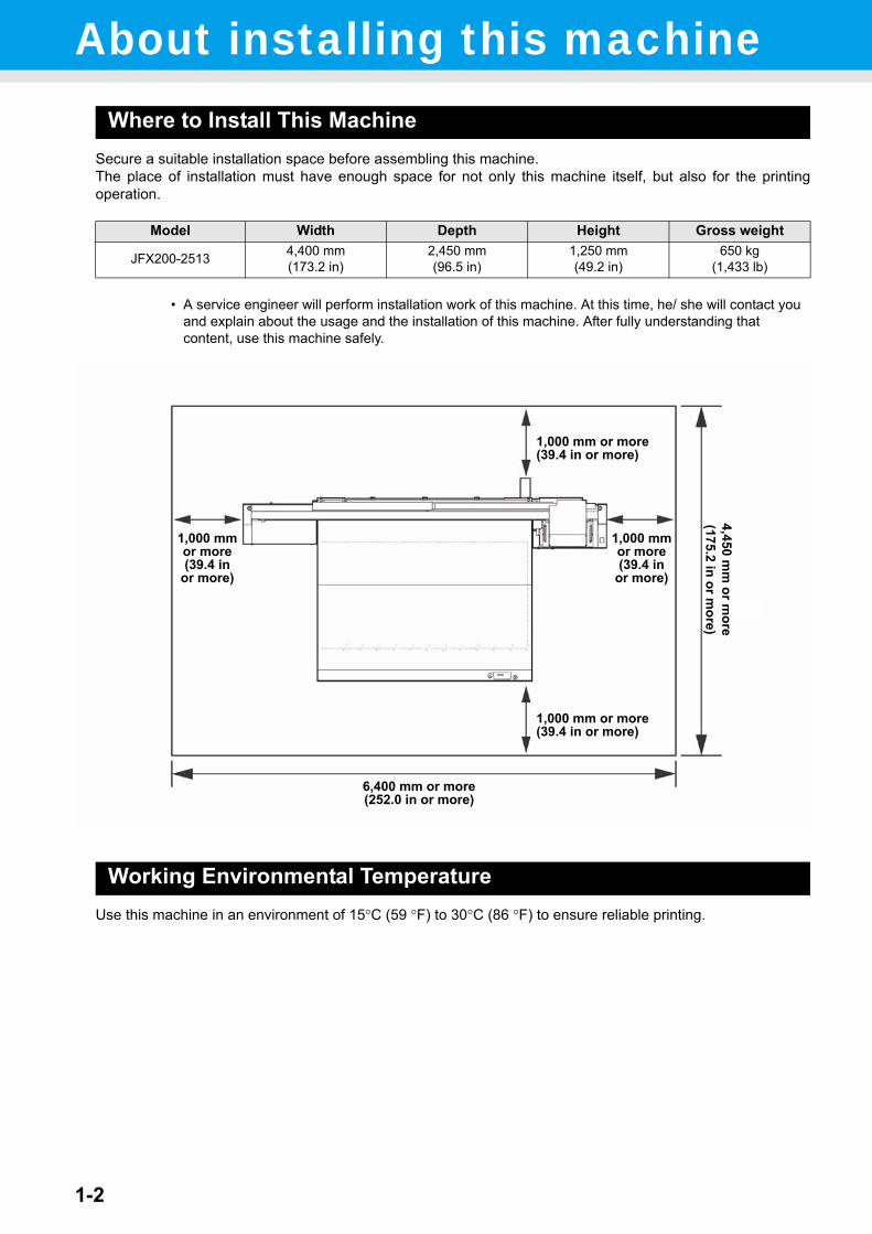
Secure a suitable installation space before assembling this machine.The place of installation must have enough space for not only this machine itself, but also for the printingoperation.
Working Environmental TemperatureUse this machine in an environment of 15°C (59 °F) to 30°C (86 °F) to ensure reliable printing.
Model Width Depth Height Gross weight
JFX200-2513 4,400 mm(173.2 in)
2,450 mm(96.5 in)
1,250 mm(49.2 in)
650 kg(1,433 lb)
• A service engineer will perform installation work of this machine. At this time, he/ she will contact you and explain about the usage and the installation of this machine. After fully understanding that content, use this machine safely.
6,400 mm or more(252.0 in or more)
1,000 mmor more(39.4 in
or more)
1,000 mmor more(39.4 in
or more)
1,000 mm or more(39.4 in or more)
1,000 mm or more(39.4 in or more)
4,450 mm
or more
(175.2 in or more)
About installing this machine
1-3
1
Before U
se
3
4
5
6
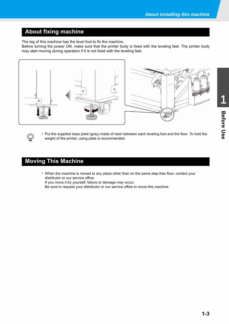
About fixing machineThe leg of this machine has the level foot to fix the machine.Before turning the power ON, make sure that the printer body is fixed with the leveling feet. The printer bodymay start moving during operation if it is not fixed with the leveling feet.
Moving This Machine
• Put the supplied base plate (gray) made of resin between each leveling foot and the floor. To hold the weight of the printer, using plate is recommended.
• When the machine is moved to any place other than on the same step-free floor, contact your distributor or our service office.If you move it by yourself, failure or damage may occur.Be sure to request your distributor or our service office to move this machine.
1-4
Names of Parts and FunctionsFront Side of the Machine
Rear Side and Right Side of the Machine
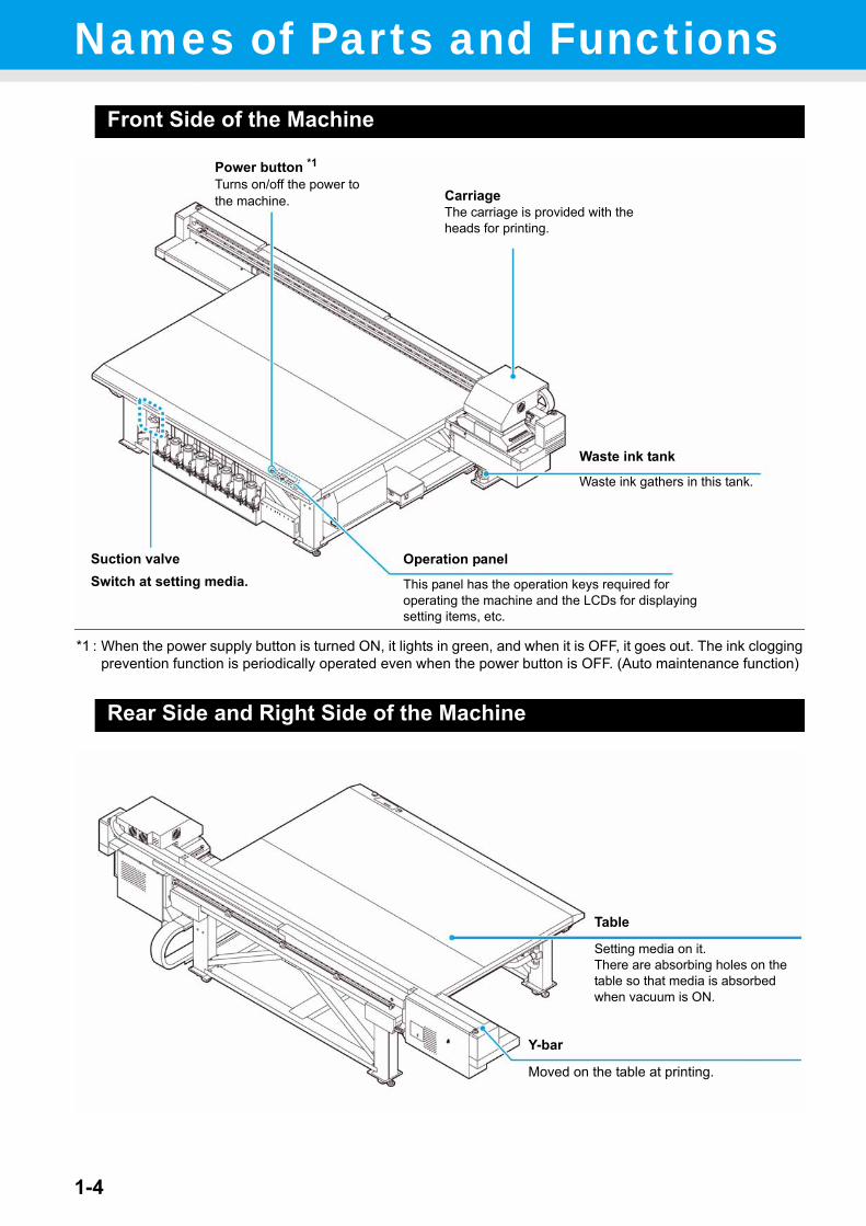
Operation panel
This panel has the operation keys required for operating the machine and the LCDs for displaying setting items, etc.
Waste ink tank
Waste ink gathers in this tank.
Suction valveSwitch at setting media.
Power button *1Turns on/off the power to the machine.
*1 : When the power supply button is turned ON, it lights in green, and when it is OFF, it goes out. The ink cloggingprevention function is periodically operated even when the power button is OFF. (Auto maintenance function)
CarriageThe carriage is provided with the heads for printing.
Y-bar
Moved on the table at printing.
Table
Setting media on it.There are absorbing holes on the table so that media is absorbed when vacuum is ON.
Names of Parts and Functions
1-5
1
Before U
se
3
4
5
6
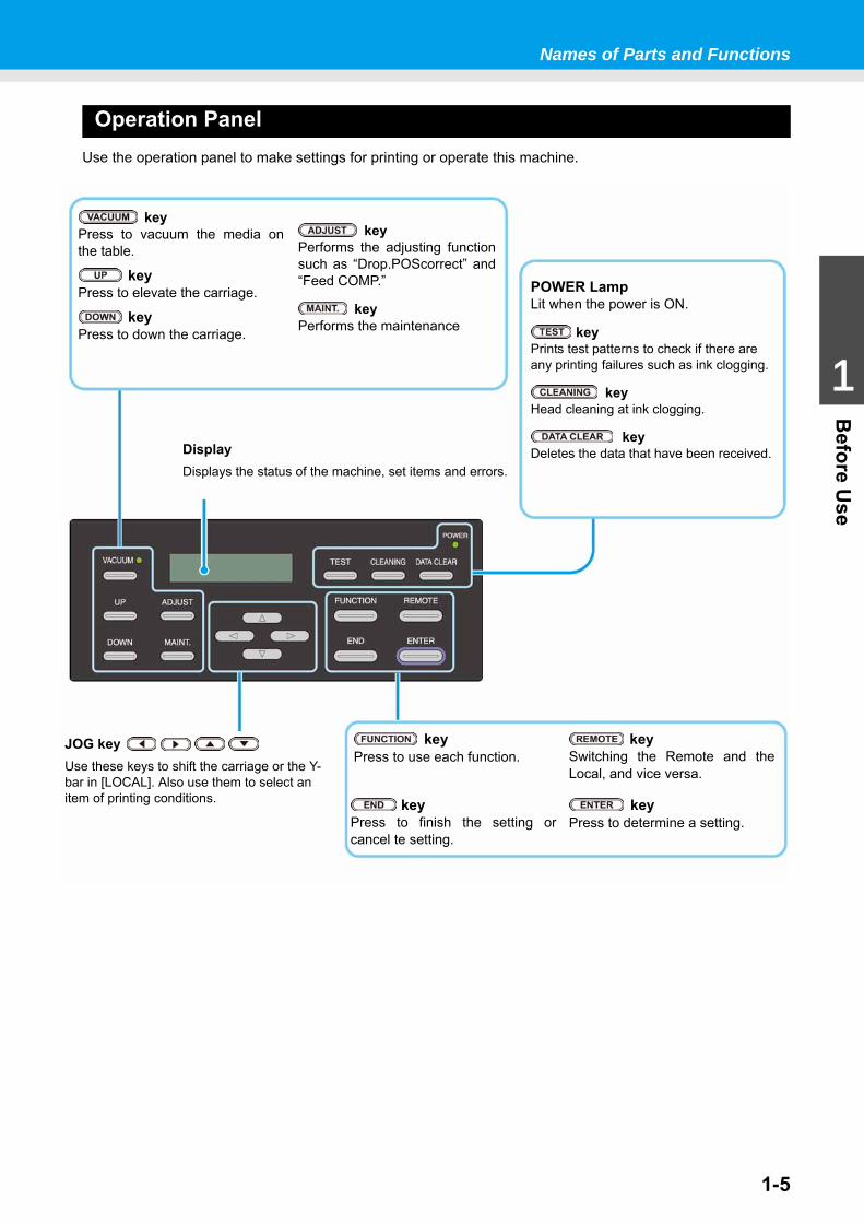
Operation PanelUse the operation panel to make settings for printing or operate this machine.
keyPress to vacuum the media onthe table.
keyPress to elevate the carriage.
keyPress to down the carriage.
JOG key Use these keys to shift the carriage or the Y-bar in [LOCAL]. Also use them to select an item of printing conditions.
DisplayDisplays the status of the machine, set items and errors.
POWER LampLit when the power is ON.
keyPrints test patterns to check if there are any printing failures such as ink clogging.
keyHead cleaning at ink clogging.
keyDeletes the data that have been received.
keyPress to use each function.
keyPress to finish the setting orcancel te setting.
keyPerforms the adjusting functionsuch as “Drop.POScorrect” and“Feed COMP.”
keyPerforms the maintenance
keySwitching the Remote and theLocal, and vice versa.
keyPress to determine a setting.
Names of Parts and Functions
1-6
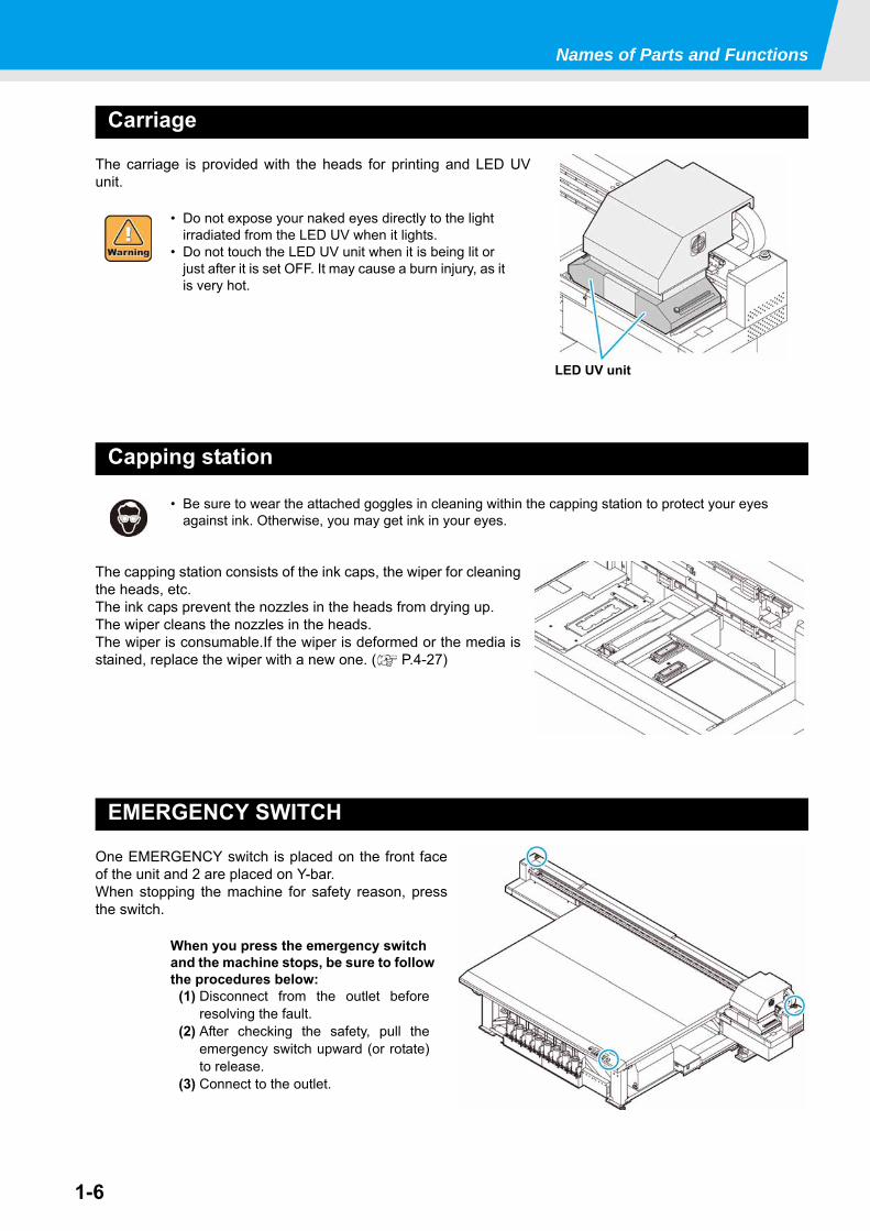
Carriage
The carriage is provided with the heads for printing and LED UVunit.
Capping station
The capping station consists of the ink caps, the wiper for cleaningthe heads, etc.The ink caps prevent the nozzles in the heads from drying up.The wiper cleans the nozzles in the heads.The wiper is consumable.If the wiper is deformed or the media isstained, replace the wiper with a new one. ( P.4-27)
EMERGENCY SWITCH
One EMERGENCY switch is placed on the front faceof the unit and 2 are placed on Y-bar.When stopping the machine for safety reason, pressthe switch.
• Do not expose your naked eyes directly to the light irradiated from the LED UV when it lights.
• Do not touch the LED UV unit when it is being lit or just after it is set OFF. It may cause a burn injury, as it is very hot.
• Be sure to wear the attached goggles in cleaning within the capping station to protect your eyes against ink. Otherwise, you may get ink in your eyes.
When you press the emergency switch and the machine stops, be sure to follow the procedures below:
(1) Disconnect from the outlet beforeresolving the fault.
(2) After checking the safety, pull theemergency switch upward (or rotate)to release.
(3) Connect to the outlet.
LED UV unit
1-7
1
Before U
se
3
4
5
6
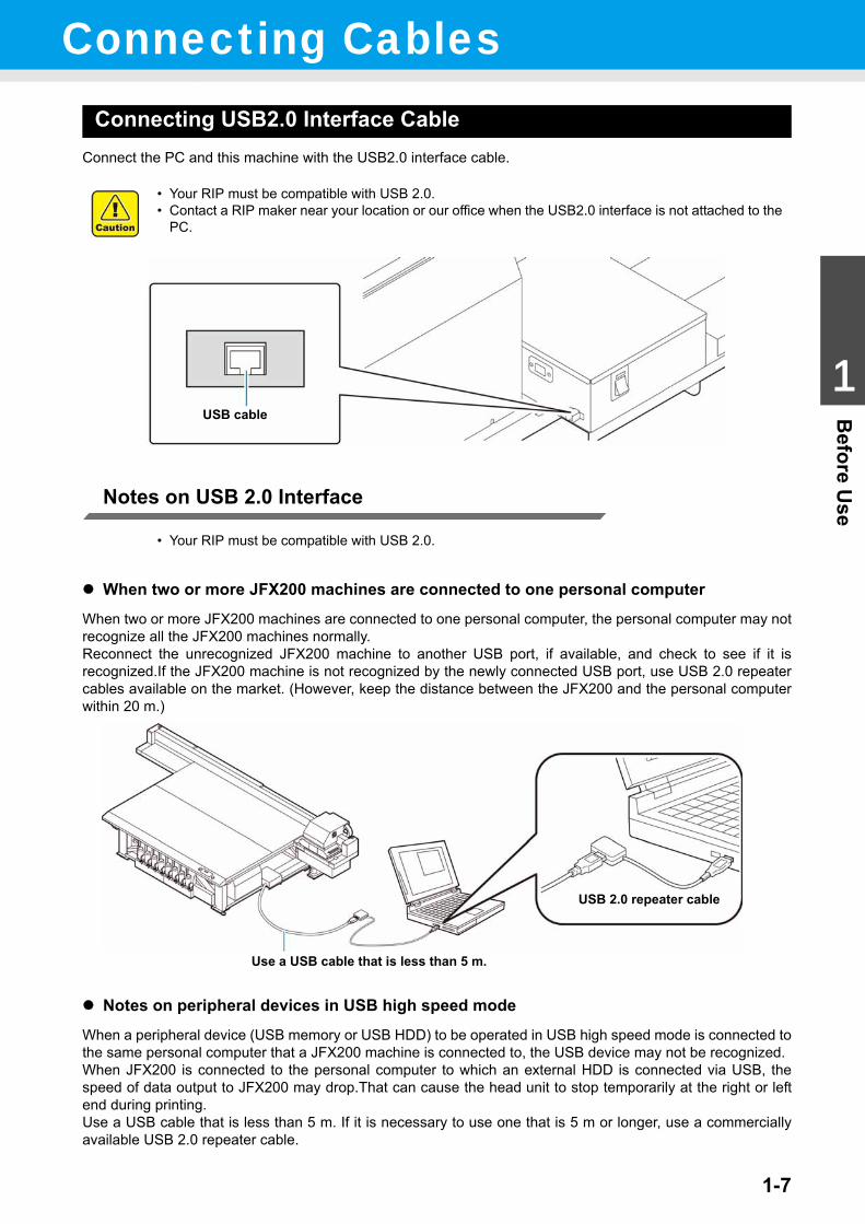
Connecting CablesConnecting USB2.0 Interface Cable
Connect the PC and this machine with the USB2.0 interface cable.
Notes on USB 2.0 Interface
When two or more JFX200 machines are connected to one personal computerWhen two or more JFX200 machines are connected to one personal computer, the personal computer may notrecognize all the JFX200 machines normally.Reconnect the unrecognized JFX200 machine to another USB port, if available, and check to see if it isrecognized.If the JFX200 machine is not recognized by the newly connected USB port, use USB 2.0 repeatercables available on the market. (However, keep the distance between the JFX200 and the personal computerwithin 20 m.)
Notes on peripheral devices in USB high speed modeWhen a peripheral device (USB memory or USB HDD) to be operated in USB high speed mode is connected tothe same personal computer that a JFX200 machine is connected to, the USB device may not be recognized.When JFX200 is connected to the personal computer to which an external HDD is connected via USB, thespeed of data output to JFX200 may drop.That can cause the head unit to stop temporarily at the right or leftend during printing.Use a USB cable that is less than 5 m. If it is necessary to use one that is 5 m or longer, use a commerciallyavailable USB 2.0 repeater cable.
• Your RIP must be compatible with USB 2.0.• Contact a RIP maker near your location or our office when the USB2.0 interface is not attached to the
PC.
• Your RIP must be compatible with USB 2.0.
USB cable
USB 2.0 repeater cable
Use a USB cable that is less than 5 m.
Connecting Cables
1-8
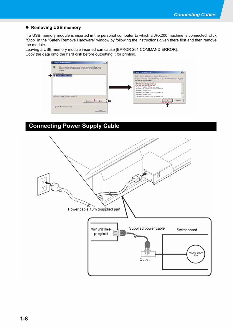
Removing USB memoryIf a USB memory module is inserted in the personal computer to which a JFX200 machine is connected, click"Stop" in the "Safely Remove Hardware" window by following the instructions given there first and then removethe module.Leaving a USB memory module inserted can cause [ERROR 201 COMMAND ERROR].Copy the data onto the hard disk before outputting it for printing.
Connecting Power Supply Cable
Power cable 10m (supplied part)
SwitchboardSupplied power cable
Outlet
Main unit three-prong inlet
1-9
1
Before U
se
3
4
5
6
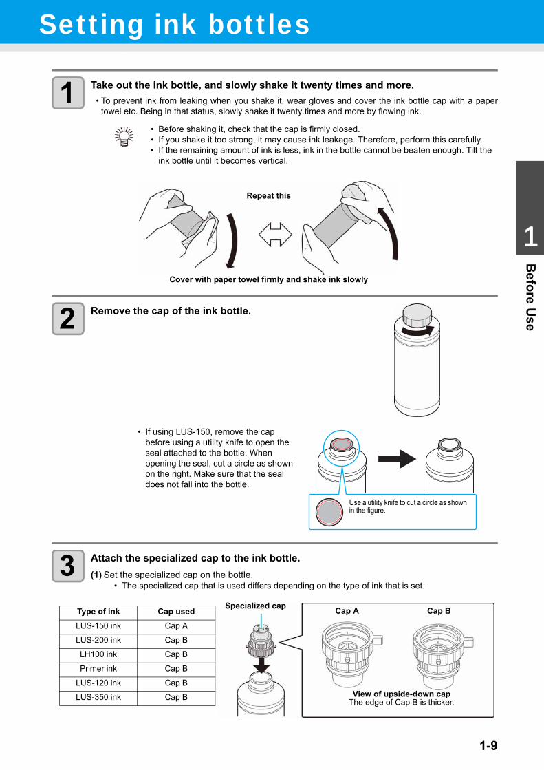
Setting ink bottles
1 Take out the ink bottle, and slowly shake it twenty times and more.• To prevent ink from leaking when you shake it, wear gloves and cover the ink bottle cap with a paper
towel etc. Being in that status, slowly shake it twenty times and more by flowing ink.
2 Remove the cap of the ink bottle.
3 Attach the specialized cap to the ink bottle.(1) Set the specialized cap on the bottle.
• The specialized cap that is used differs depending on the type of ink that is set.
• Before shaking it, check that the cap is firmly closed.• If you shake it too strong, it may cause ink leakage. Therefore, perform this carefully.• If the remaining amount of ink is less, ink in the bottle cannot be beaten enough. Tilt the
ink bottle until it becomes vertical.
• If using LUS-150, remove the cap before using a utility knife to open the seal attached to the bottle. When opening the seal, cut a circle as shown on the right. Make sure that the seal does not fall into the bottle.
Cover with paper towel firmly and shake ink slowly
Repeat this
Use a utility knife to cut a circle as shown in the figure.
Cap A Cap B
View of upside-down capThe edge of Cap B is thicker.
Specialized capType of ink Cap usedLUS-150 ink Cap A
LUS-200 ink Cap B
LH100 ink Cap B
Primer ink Cap B
LUS-120 ink Cap B
LUS-350 ink Cap B
1-10
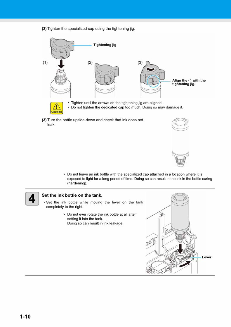
(2) Tighten the specialized cap using the tightening jig.
(3) Turn the bottle upside-down and check that ink does notleak.
4 Set the ink bottle on the tank.• Set the ink bottle while moving the lever on the tank
completely to the right.
• Do not leave an ink bottle with the specialized cap attached in a location where it is exposed to light for a long period of time. Doing so can result in the ink in the bottle curing (hardening).
• Do not ever rotate the ink bottle at all after setting it into the tank. Doing so can result in ink leakage.
Align the with the tightening jig.
Tightening jig
• Tighten until the arrows on the tightening jig are aligned.• Do not tighten the dedicated cap too much. Doing so may damage it.
Lever
Setting ink bottles
1-11
1
Before U
se
3
4
5
6
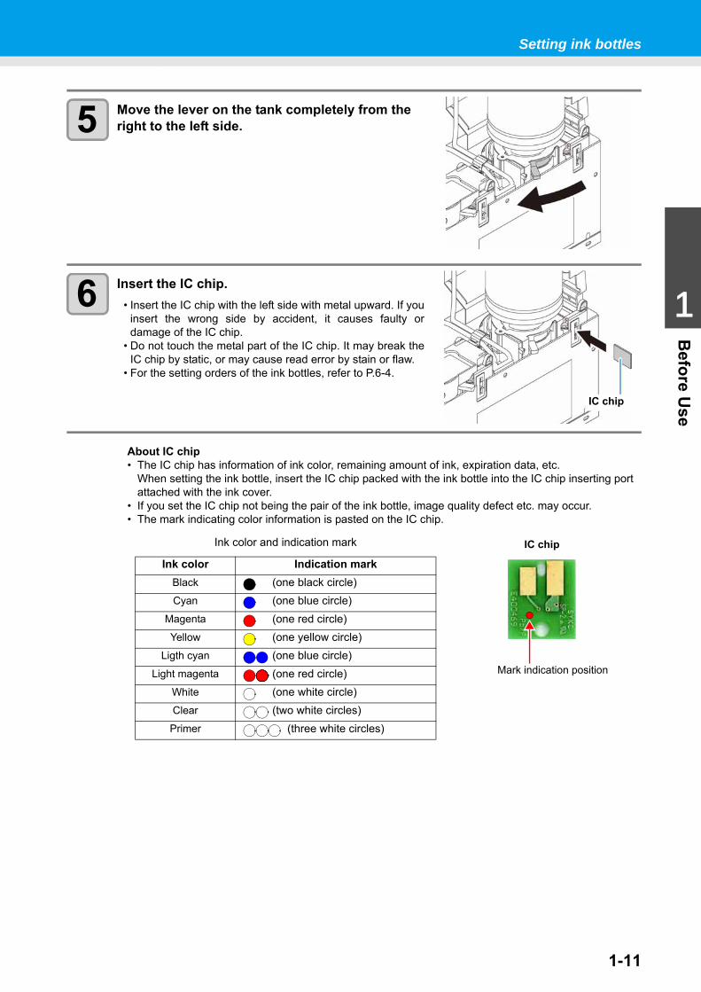
5 Move the lever on the tank completely from the right to the left side.
6 Insert the IC chip.• Insert the IC chip with the left side with metal upward. If you
insert the wrong side by accident, it causes faulty ordamage of the IC chip.
• Do not touch the metal part of the IC chip. It may break theIC chip by static, or may cause read error by stain or flaw.
• For the setting orders of the ink bottles, refer to P.6-4.
About IC chip• The IC chip has information of ink color, remaining amount of ink, expiration data, etc.
When setting the ink bottle, insert the IC chip packed with the ink bottle into the IC chip inserting port attached with the ink cover.
• If you set the IC chip not being the pair of the ink bottle, image quality defect etc. may occur.• The mark indicating color information is pasted on the IC chip.
IC chip
Ink color and indication mark
Ink color Indication markBlack (one black circle)Cyan (one blue circle)
Magenta (one red circle)Yellow (one yellow circle)
Ligth cyan (one blue circle)Light magenta (one red circle)
White (one white circle)Clear (two white circles)Primer (three white circles)
IC chip
Mark indication position
1-12
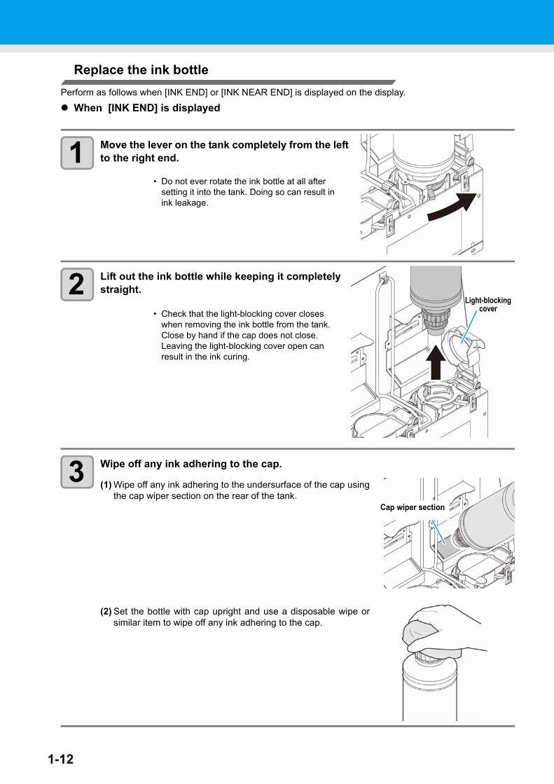
Replace the ink bottlePerform as follows when [INK END] or [INK NEAR END] is displayed on the display.
When [INK END] is displayed
1 Move the lever on the tank completely from the left to the right end.
2 Lift out the ink bottle while keeping it completely straight.
3 Wipe off any ink adhering to the cap.
(1) Wipe off any ink adhering to the undersurface of the cap usingthe cap wiper section on the rear of the tank.
(2) Set the bottle with cap upright and use a disposable wipe orsimilar item to wipe off any ink adhering to the cap.
• Do not ever rotate the ink bottle at all after setting it into the tank. Doing so can result in ink leakage.
• Check that the light-blocking cover closes when removing the ink bottle from the tank. Close by hand if the cap does not close. Leaving the light-blocking cover open can result in the ink curing.
Light-blocking cover
Cap wiper section
Setting ink bottles
1-13
1
Before U
se
3
4
5
6
4 Remove the cap from the used ink bottle.• Use the tightening jig to remove the cap if it is difficult to remove.
5 Refer to P.1-9 “Setting ink bottles” to set the new ink bottle.
When [INK NEAR END] is displayedThere is a little of ink left. It is recommended to replace the ink bottle soon since ink may become empty inprinting while printing is continuously enabled.When you press the key in LOCAL, you can check the bottle to be replaced in the local guidance.( P.3-30)
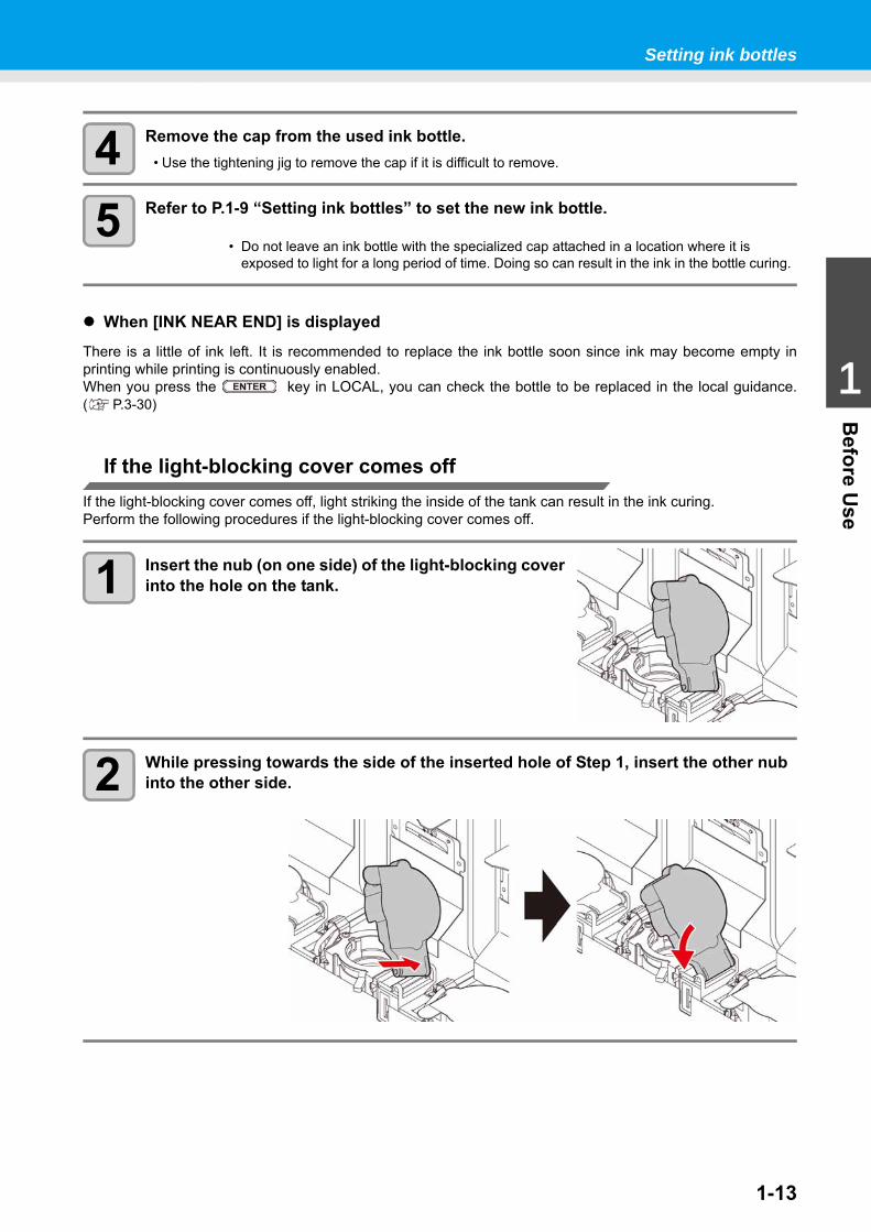
If the light-blocking cover comes offIf the light-blocking cover comes off, light striking the inside of the tank can result in the ink curing.Perform the following procedures if the light-blocking cover comes off.
1 Insert the nub (on one side) of the light-blocking cover into the hole on the tank.
2 While pressing towards the side of the inserted hole of Step 1, insert the other nub into the other side.
• Do not leave an ink bottle with the specialized cap attached in a location where it is exposed to light for a long period of time. Doing so can result in the ink in the bottle curing.
1-14
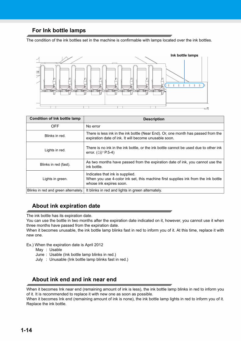
For Ink bottle lampsThe condition of the ink bottles set in the machine is confirmable with lamps located over the ink bottles.
About ink expiration dateThe ink bottle has its expiration date.You can use the bottle in two months after the expiration date indicated on it, however, you cannot use it whenthree months have passed from the expiration date.When it becomes unusable, the ink bottle lamp blinks fast in red to inform you of it. At this time, replace it withnew one.
Ex.) When the expiration date is April 2012May : UsableJune : Usable (Ink bottle lamp blinks in red.)July : Unusable (Ink bottle lamp blinks fast in red.)
About ink end and ink near endWhen it becomes Ink near end (remaining amount of ink is less), the ink bottle lamp blinks in red to inform youof it. It is recommended to replace it with new one as soon as possible.When it becomes Ink end (remaining amount of ink is none), the ink bottle lamp lights in red to inform you of it.Replace the ink bottle.
Condition of Ink bottle lamp Description
OFF No error
Blinks in red. There is less ink in the ink bottle (Near End). Or, one month has passed from theexpiration date of ink. It will become unusable soon.
Lights in red. There is no ink in the ink bottle, or the ink bottle cannot be used due to other inkerror. ( P.5-4)
Blinks in red (fast). As two months have passed from the expiration date of ink, you cannot use theink bottle.
Lights in green.Indicates that ink is supplied.When you use 4-color ink set, this machine first supplies ink from the ink bottlewhose ink expires soon.
Blinks in red and green alternately. It blinks in red and lights in green alternately.
Ink bottle lamps
Setting ink bottles
1-15
1
Before U
se
3
4
5
6
Caution in handling of ink bottles
• If you get ink in your eyes, immediately wash your eyes with a lot of clean running water for at least 15 minutes. In doing so, also wash the eyess to rinse ink away completely. Then, consult a doctor as soon as possible.
• Use genuine ink bottles for this machine. This machine functions by recognizing the genuine ink bottles. In case of troubles caused by modified ink bottles or the like, it shall be out of the warranty even within the warranty period.
• Store the ink bottle in a place not more than 1 m off the ground. If you store it in a place higher than 1 m, should the ink bottle fall, the cap may come off, spilling the ink.
• If the ink bottle is moved from a cold place to a warm place, leave it in the room temperature for three hours or more before using it.
• Make sure to store ink bottles in a cool and dark place.• Store ink bottles and waste ink tank in a place that is out of the reach of children.• Request an industrial waste processor for processing of empty ink bottles.• Be sure to thoroughly consume the ink in the ink bottle, once it is opened, within three months. If an
extended period of time has passed away after opening the ink bottle, printing quality would be poor.• Do not shake ink bottles violently. This may result in ink leakage from the ink bottles.• Never refill the ink bottles with ink. This may result in troubles.
MIMAKI will not bear any responsibility for any damage caused by the use of the ink bottles refilled with ink.
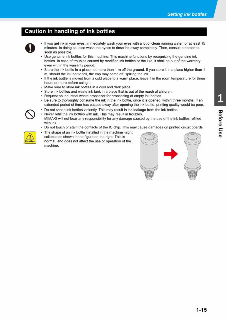
• Do not touch or stain the contacts of the IC chip. This may cause damages on printed circuit boards.• The shape of an ink bottle installed in the machine might
collapse as shown in the figure on the right. This is normal, and does not affect the use or operation of the machine.
1-16
MediaUsable media sizes and notes for handling are described.
Usable sizes of media
Caution in handling of mediasPay attention to the followings for handling of medias.
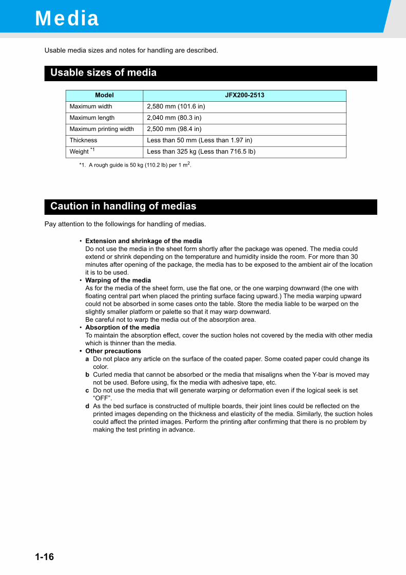
Model JFX200-2513Maximum width 2,580 mm (101.6 in)
Maximum length 2,040 mm (80.3 in)
Maximum printing width 2,500 mm (98.4 in)
Thickness Less than 50 mm (Less than 1.97 in)
Weight *1
*1. A rough guide is 50 kg (110.2 lb) per 1 m2.
Less than 325 kg (Less than 716.5 lb)
• Extension and shrinkage of the mediaDo not use the media in the sheet form shortly after the package was opened. The media could extend or shrink depending on the temperature and humidity inside the room. For more than 30 minutes after opening of the package, the media has to be exposed to the ambient air of the location it is to be used.
• Warping of the mediaAs for the media of the sheet form, use the flat one, or the one warping downward (the one with floating central part when placed the printing surface facing upward.) The media warping upward could not be absorbed in some cases onto the table. Store the media liable to be warped on the slightly smaller platform or palette so that it may warp downward.Be careful not to warp the media out of the absorption area.
• Absorption of the mediaTo maintain the absorption effect, cover the suction holes not covered by the media with other media which is thinner than the media.
• Other precautionsa Do not place any article on the surface of the coated paper. Some coated paper could change its
color.b Curled media that cannot be absorbed or the media that misaligns when the Y-bar is moved may
not be used. Before using, fix the media with adhesive tape, etc.c Do not use the media that will generate warping or deformation even if the logical seek is set
“OFF”.d As the bed surface is constructed of multiple boards, their joint lines could be reflected on the
printed images depending on the thickness and elasticity of the media. Similarly, the suction holes could affect the printed images. Perform the printing after confirming that there is no problem by making the test printing in advance.
This chapter
describes procedures and setting methods for ink and media preparation, and printing.
Workflow .......................................................2-2Turning the Power ON/OFF ..........................2-3
Turning the Power ON ................................ 2-3Turning the Power OFF ............................... 2-4
Setting a Media .............................................2-5Setting the Media ........................................ 2-5
Move the irradiation position of the UV lamp 2-8Test Printing ................................................2-13
Test Printing .............................................. 2-14
Head Cleaning ............................................2-15About head cleaning ..................................2-15Perform head cleaning depending on the test printing result ......................................2-15
Printing Data ...............................................2-16Starting a Printing Operation .....................2-16Stopping a printing operation halfway ........2-17Deleting Received Data (Data Clear) ........2-17Move the Y-bar ..........................................2-18
Chapter 2Basic Operations
2-2
Workflow
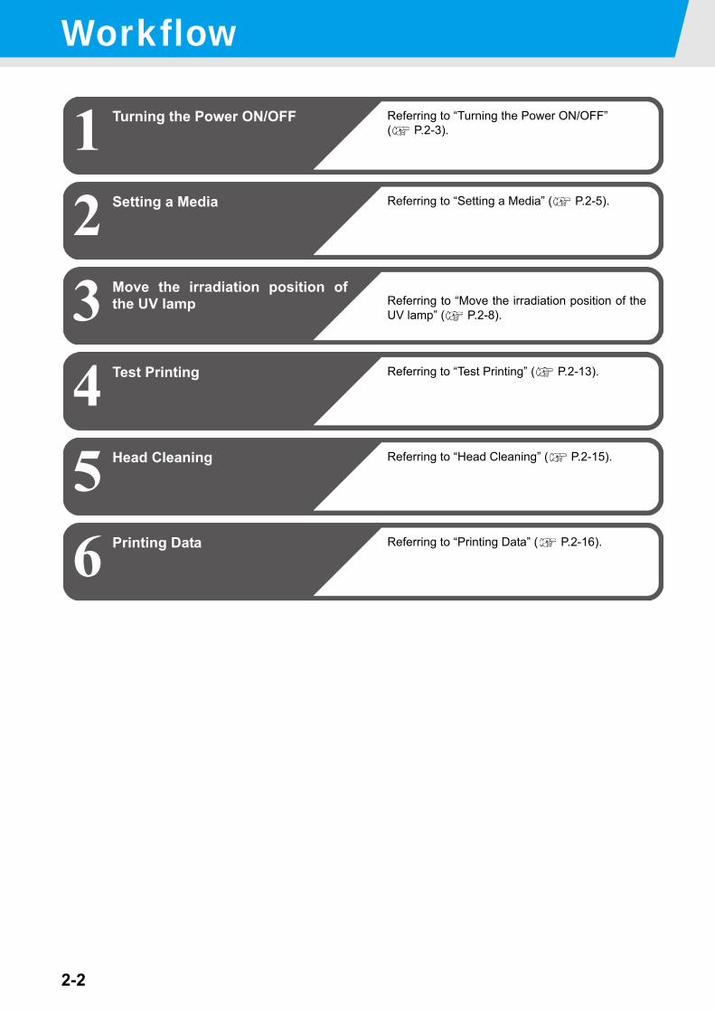
1 Turning the Power ON/OFF Referring to “Turning the Power ON/OFF” ( P.2-3).
23
Setting a Media
5
Referring to “Setting a Media” ( P.2-5).
4
Printing Data Referring to “Printing Data” ( P.2-16).6
Test Printing Referring to “Test Printing” ( P.2-13).
Head Cleaning Referring to “Head Cleaning” ( P.2-15).
Move the irradiation position ofthe UV lamp Referring to “Move the irradiation position of the
UV lamp” ( P.2-8).
2-3
1
2
Basic O
perations
4
5
6
Turning the Power ON/OFFTurning the Power ON
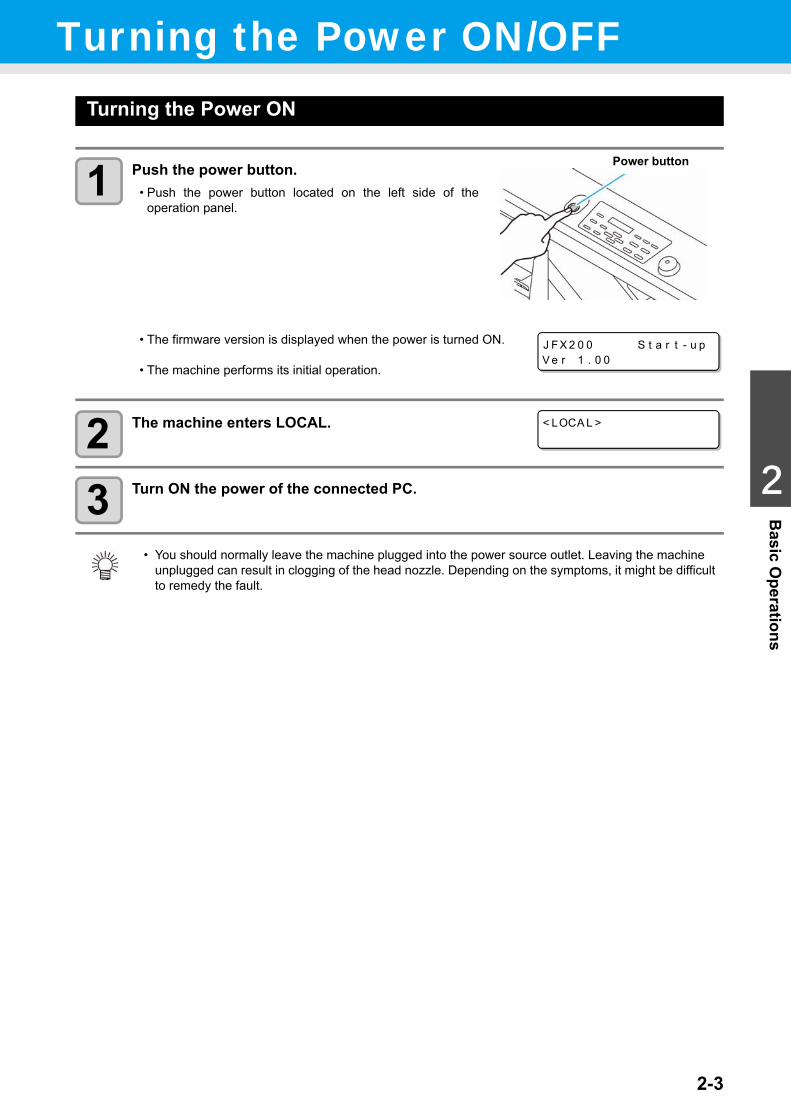
1 Push the power button.• Push the power button located on the left side of the
operation panel.
• The firmware version is displayed when the power is turned ON.
• The machine performs its initial operation.
2 The machine enters LOCAL.
3 Turn ON the power of the connected PC.
• You should normally leave the machine plugged into the power source outlet. Leaving the machine unplugged can result in clogging of the head nozzle. Depending on the symptoms, it might be difficult to remedy the fault.
Power button
J FX 2 0 0 S t a r t - u pV e r 1 . 0 0
< LOCA L >
2-4
Turning the Power ON/OFF
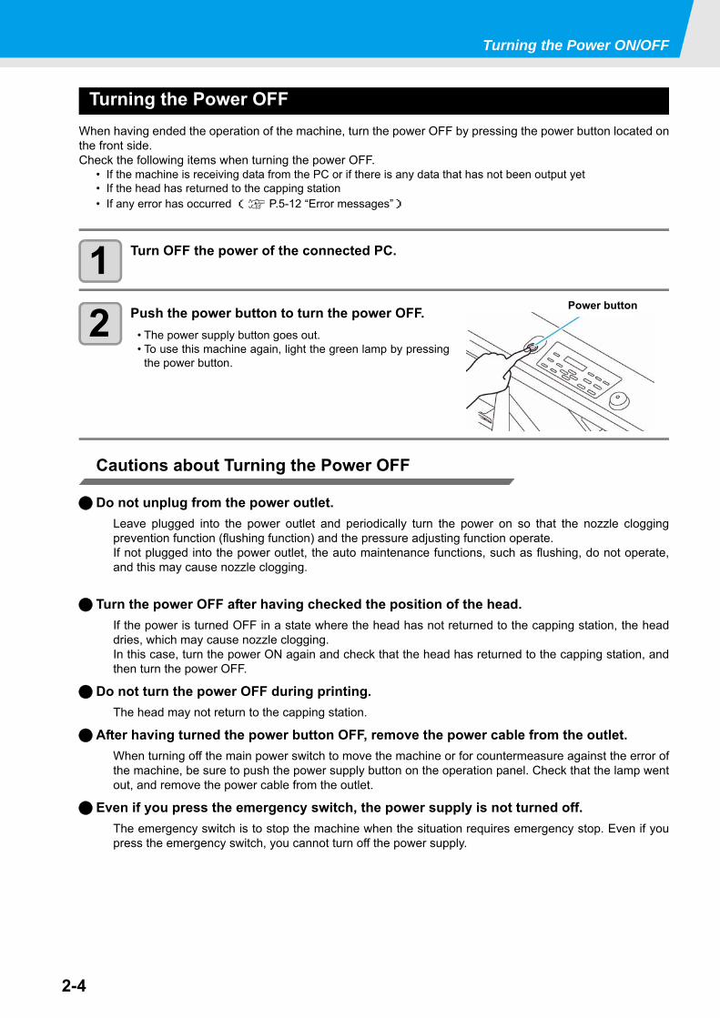
Turning the Power OFFWhen having ended the operation of the machine, turn the power OFF by pressing the power button located onthe front side.Check the following items when turning the power OFF.
• If the machine is receiving data from the PC or if there is any data that has not been output yet• If the head has returned to the capping station• If any error has occurred ( P.5-12 “Error messages”)
1 Turn OFF the power of the connected PC.
2 Push the power button to turn the power OFF.• The power supply button goes out.• To use this machine again, light the green lamp by pressing
the power button.
Cautions about Turning the Power OFF
Do not unplug from the power outlet.Leave plugged into the power outlet and periodically turn the power on so that the nozzle cloggingprevention function (flushing function) and the pressure adjusting function operate.If not plugged into the power outlet, the auto maintenance functions, such as flushing, do not operate,and this may cause nozzle clogging.
Turn the power OFF after having checked the position of the head.If the power is turned OFF in a state where the head has not returned to the capping station, the headdries, which may cause nozzle clogging.In this case, turn the power ON again and check that the head has returned to the capping station, andthen turn the power OFF.
Do not turn the power OFF during printing.The head may not return to the capping station.
After having turned the power button OFF, remove the power cable from the outlet.When turning off the main power switch to move the machine or for countermeasure against the error ofthe machine, be sure to push the power supply button on the operation panel. Check that the lamp wentout, and remove the power cable from the outlet.
Even if you press the emergency switch, the power supply is not turned off.The emergency switch is to stop the machine when the situation requires emergency stop. Even if youpress the emergency switch, you cannot turn off the power supply.
Power button
2-5
1
2
Basic O
perations
4
5
6
Setting a MediaThis machine can be used with a leaf media.For usable medias, refer to P.1-16 “Usable sizes of media”.
Setting the Media
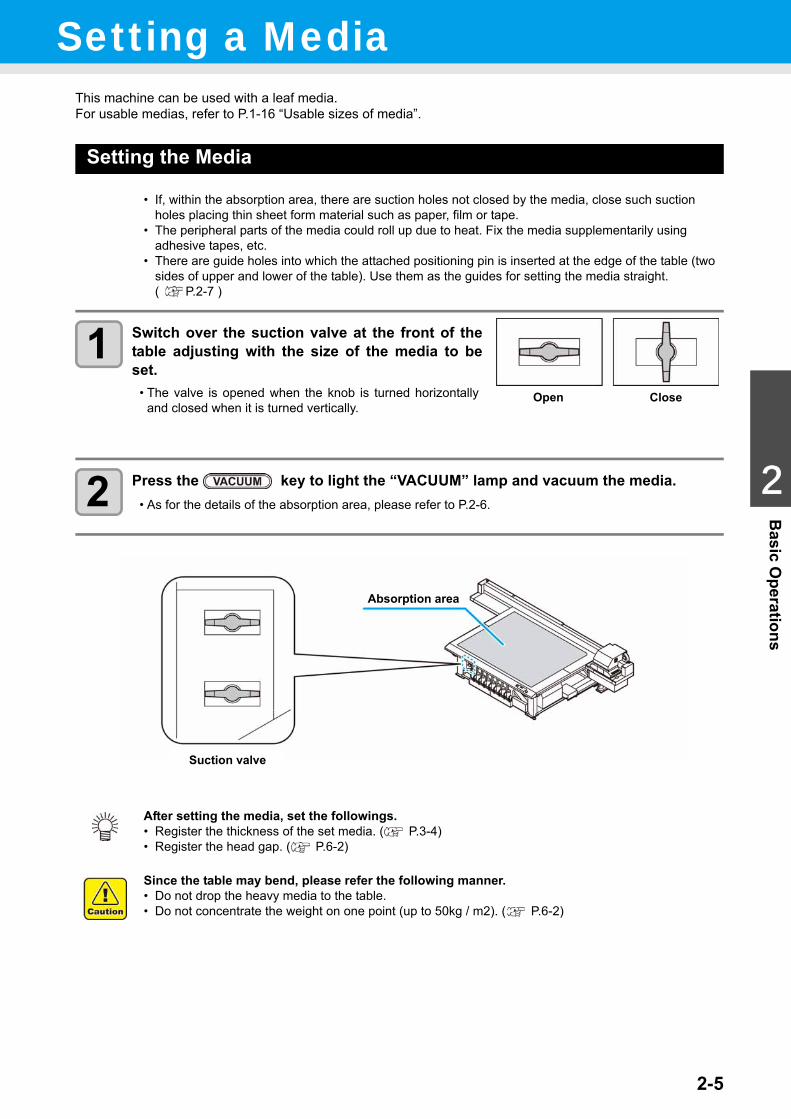
1 Switch over the suction valve at the front of thetable adjusting with the size of the media to beset.
• The valve is opened when the knob is turned horizontallyand closed when it is turned vertically.
2 Press the key to light the “VACUUM” lamp and vacuum the media.• As for the details of the absorption area, please refer to P.2-6.
• If, within the absorption area, there are suction holes not closed by the media, close such suction holes placing thin sheet form material such as paper, film or tape.
• The peripheral parts of the media could roll up due to heat. Fix the media supplementarily using adhesive tapes, etc.
• There are guide holes into which the attached positioning pin is inserted at the edge of the table (two sides of upper and lower of the table). Use them as the guides for setting the media straight. ( P.2-7 )
After setting the media, set the followings.• Register the thickness of the set media. ( P.3-4)• Register the head gap. ( P.6-2)
Since the table may bend, please refer the following manner.• Do not drop the heavy media to the table.• Do not concentrate the weight on one point (up to 50kg / m2). ( P.6-2)
Open Close
Suction valve
Absorption area
2-6
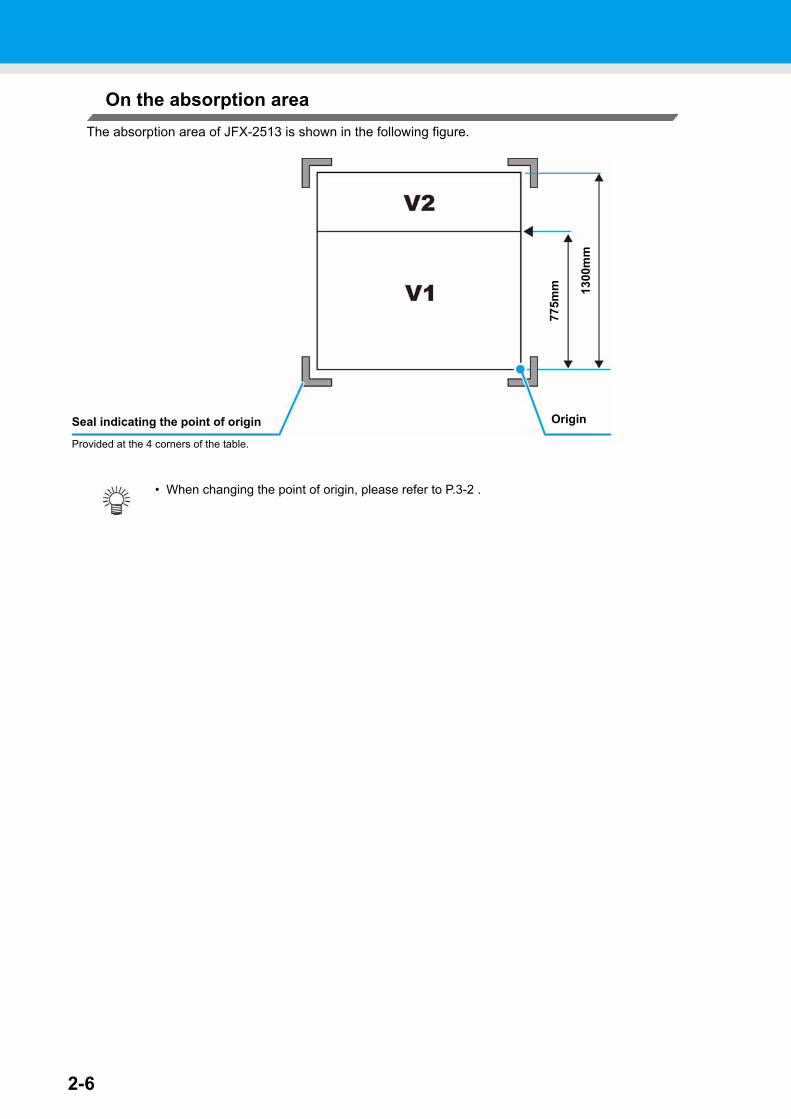
On the absorption areaThe absorption area of JFX-2513 is shown in the following figure.
• When changing the point of origin, please refer to P.3-2 .
OriginSeal indicating the point of origin
Provided at the 4 corners of the table.
775m
m 1300
mm
2-7
1
2
Basic O
perations
4
5
6
Setting a Media
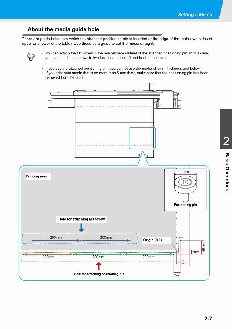
About the media guide holeThere are guide holes into which the attached positioning pin is inserted at the edge of the table (two sides ofupper and lower of the table). Use these as a guide to set the media straight.
• You can attach the M3 screw in the marketplace instead of the attached positioning pin. In this case, you can attach the screws in two locations at the left and front of the table.
• If you use the attached positioning pin, you cannot use the media of 5mm thickness and below.• If you print onto media that is no more than 5 mm thick, make sure that the positioning pin has been
removed from the table.
Hole for attaching positioning pin
Hole for attaching M3 screw
Printing aera
Positioning pin
Origin (0,0)
2-8
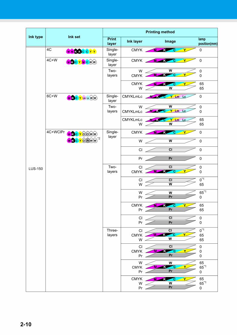
Move the irradiation position of the UV lampWhen printing with this machine, it is necessary to move the LED UV position according to ink to use (color ink/ special colorink).
This machine provides three printing methods:
Single-layer printing: printing color ink layer on media Two-layers printing: printing special color ink (white or clear or primer) layer on color ink layer Two-layers printing: printing color ink layer on special color ink layer Two-layers printing: printing special color ink layer on special color ink layer Three-layers printing: A color ink layer is overlaid on the special color ink layer, and a
special color ink layer is overlaid thereon
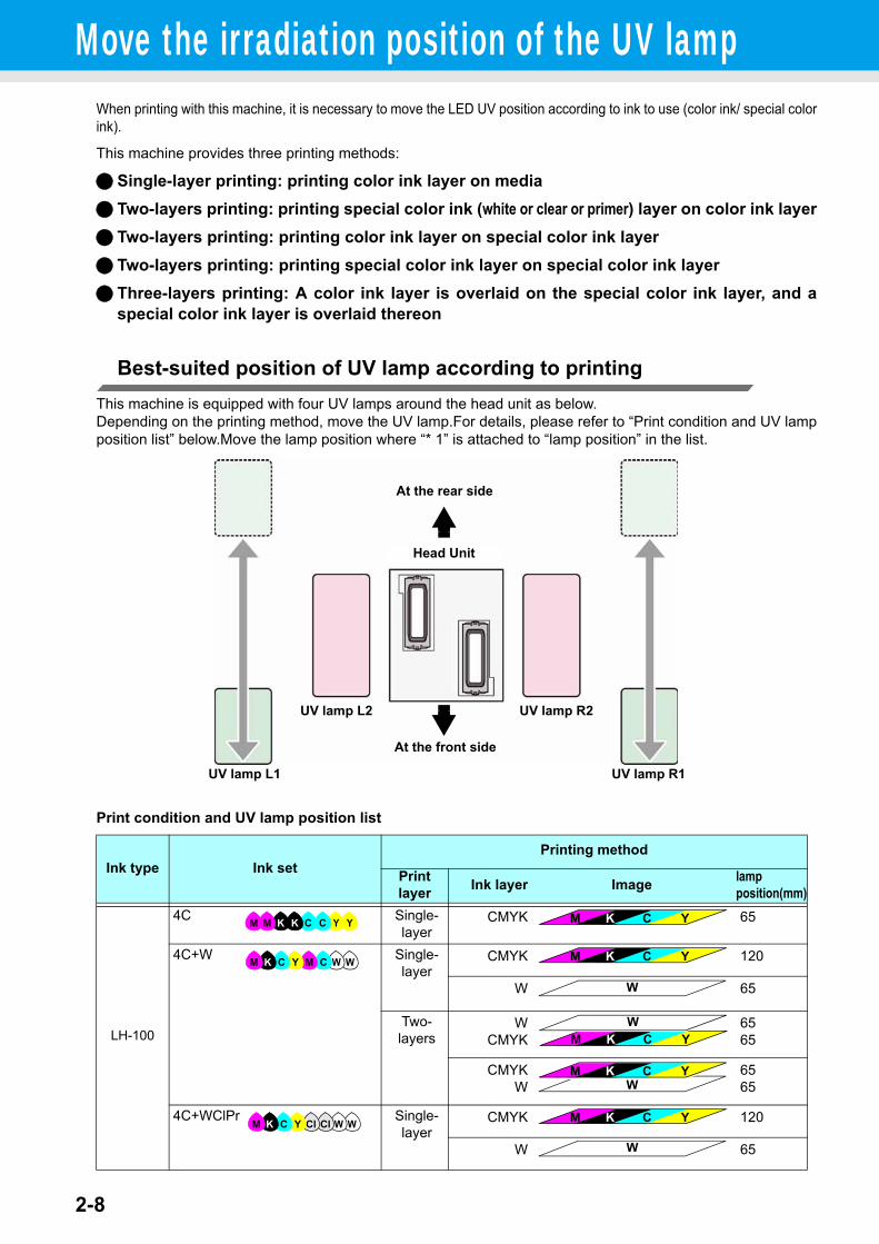
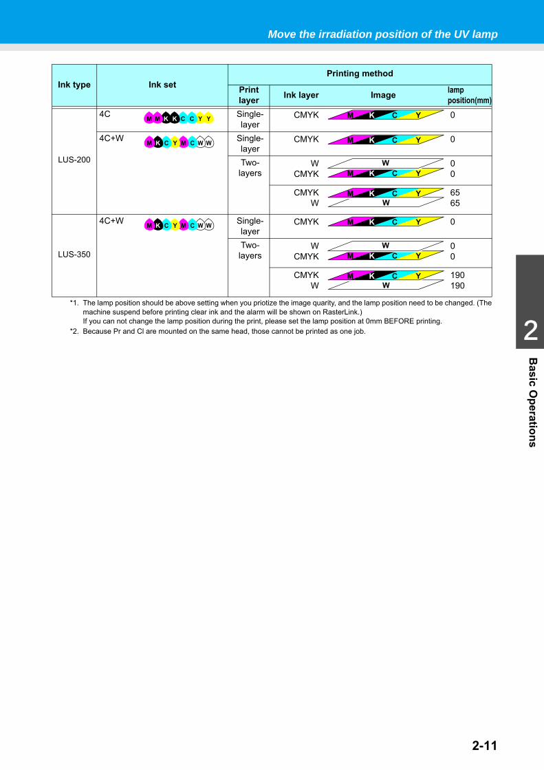
Best-suited position of UV lamp according to printingThis machine is equipped with four UV lamps around the head unit as below.Depending on the printing method, move the UV lamp.For details, please refer to “Print condition and UV lampposition list” below.Move the lamp position where “* 1” is attached to “lamp position” in the list.
Print condition and UV lamp position list
Ink type Ink setPrinting method
Print layer Ink layer Image lamp
position(mm)
LH-100
4C Single-layer
CMYK 65
4C+W Single-layer
CMYK 120
W 65
Two-layers
WCMYK
6565
CMYKW
6565
4C+WClPr Single-layer
CMYK 120
W 65
UV lamp L1
UV lamp L2
UV lamp R1
UV lamp R2
At the front side
At the rear side
Head Unit
YYCCKKMM M K C Y
WWCMYCKM M K C Y
W
M K C YW
WM K C Y
WWClClYCKM M K C Y
W
2-9
1
2
Basic O
perations
4
5
6
Move the irradiation position of the UV lamp
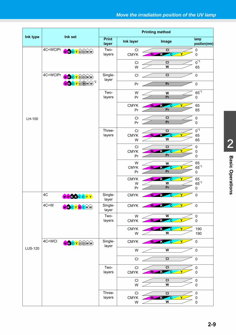
LH-100
4C+WClPr Two-layers
ClCMYK
00
ClW
0*1
65
4C+WClPr
*2
Single-layer
Cl 0
Pr 0
Two-layers
WPr
65*1
0
CMYKPr
6565
ClPr
00
Three-layers
ClCMYK
W
0*1
6565
ClCMYK
Pr
000
WCMYK
Pr
6565*1
0
CMYKWPr
6565*1
0
LUS-120
4C Single-layer
CMYK 0
4C+W Single-layer
CMYK 0
Two-layers
WCMYK
00
CMYKW
190190
4C+WCl Single-layer
CMYK 0
W 0
Cl 0
Two-layers
ClCMYK
00
ClW
00
Three-layers
ClCMYK
W
000
Ink type Ink setPrinting method
Print layer Ink layer Image lamp
position(mm)
WWClClYCKMM K C Y
Cl
WCl
WWClClYCKM
WWPrClYCKM
Cl
Pr
PrW
PrM K C Y
PrCl
WM K C Y
Cl
PrM K C Y
Cl
PrM K C Y
W
PrW
M K C Y
YYCCKKMM M K C Y
WWCMYCKM M K C Y
M K C YW
WM K C Y
WWClClYCKM M K C Y
W
Cl
M K C YCl
WCl
WM K C Y
Cl
2-10
LUS-150
4C Single-layer
CMYK 0
4C+W Single-layer
CMYK 0
Two-layers
WCMYK
00
CMYKW
6565
6C+W Single-layer
CMYKLmLc 0
Two-layers
WCMYKLmLc
00
CMYKLmLcW
6565
4C+WClPr*2
Single-layer
CMYK 0
W 0
Cl 0
Pr 0
Two-layers
ClCMYK
00
ClW
0*1
65
WPr
65*1
0
CMYKPr
6565
ClPr
00
Three-layers
ClCMYK
W
0*1
6565
ClCMYK
Pr
000
WCMYK
Pr
6565*1
0
CMYKWPr
6565*1
0
Ink type Ink setPrinting method
Print layer Ink layer Image lamp
position(mm)
YYCCKKMM M K C Y
WWCMYCKM M K C Y
M K C YW
WM K C Y
WWLcLmYCKM M K C Y Lm Lc
M K C Y Lm LcW
WM K C Y Lm Lc
WWClClYCKM
WWPrClYCKM
M K C Y
W
Cl
Pr
M K C YCl
WCl
PrW
PrM K C Y
PrCl
WM K C Y
Cl
PrM K C Y
Cl
PrM K C Y
W
PrW
M K C Y
2-11
1
2
Basic O
perations
4
5
6
Move the irradiation position of the UV lamp
LUS-200
4C Single-layer
CMYK 0
4C+W Single-layer
CMYK 0
Two-layers
WCMYK
00
CMYKW
6565
LUS-350
4C+W Single-layer
CMYK 0
Two-layers
WCMYK
00
CMYKW
190190
*1. The lamp position should be above setting when you priotize the image quarity, and the lamp position need to be changed. (Themachine suspend before printing clear ink and the alarm will be shown on RasterLink.) If you can not change the lamp position during the print, please set the lamp position at 0mm BEFORE printing.
*2. Because Pr and Cl are mounted on the same head, those cannot be printed as one job.
Ink type Ink setPrinting method
Print layer Ink layer Image lamp
position(mm)
YYCCKKMM M K C Y
WWCMYCKM M K C Y
M K C YW
WM K C Y
WWCMYCKM M K C Y
M K C YW
WM K C Y
2-12
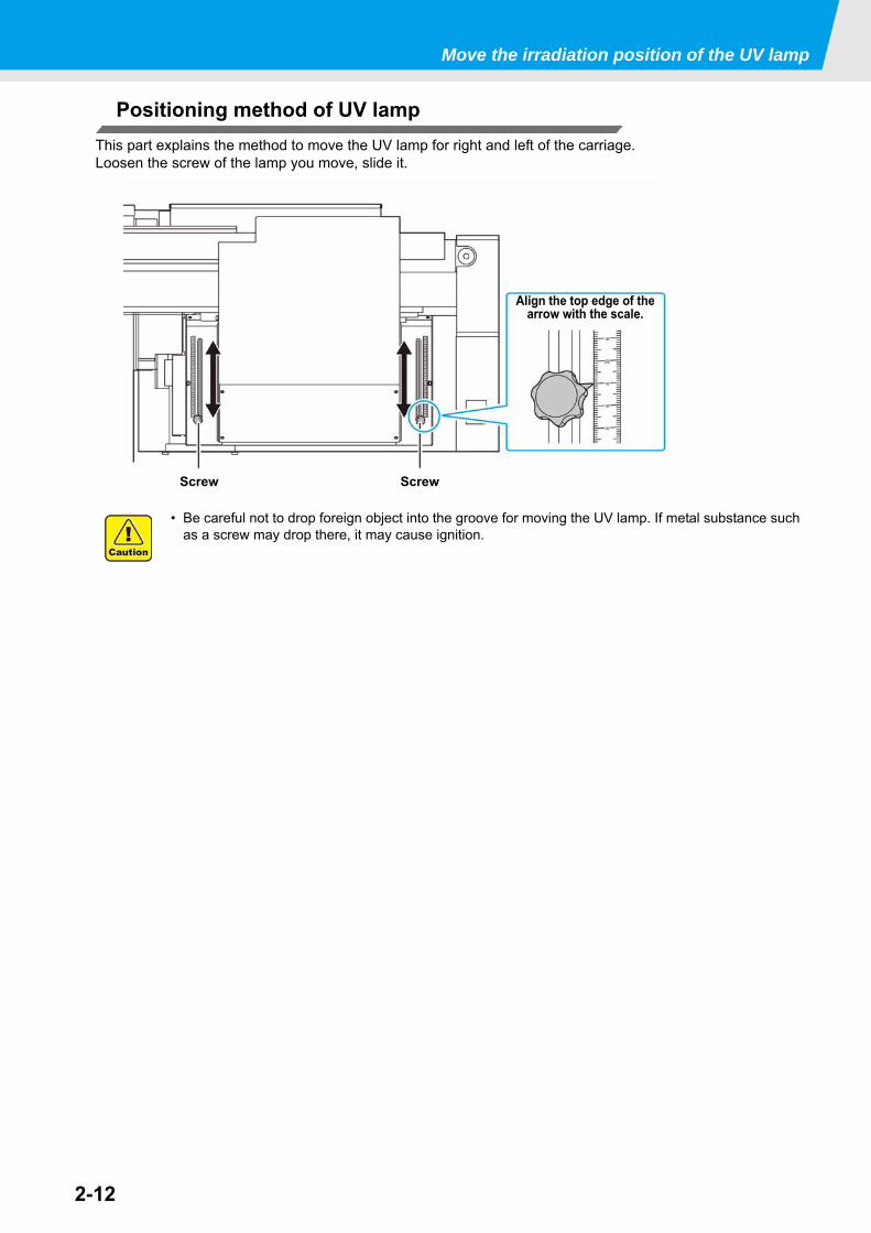
Move the irradiation position of the UV lamp
Positioning method of UV lampThis part explains the method to move the UV lamp for right and left of the carriage.Loosen the screw of the lamp you move, slide it.
• Be careful not to drop foreign object into the groove for moving the UV lamp. If metal substance such as a screw may drop there, it may cause ignition.
ScrewScrew
Align the top edge of the arrow with the scale.
2-13
1
2
Basic O
perations
4
5
6
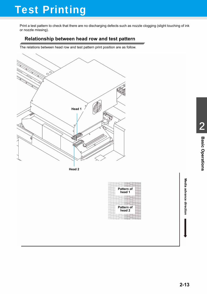
Test PrintingPrint a test pattern to check that there are no discharging defects such as nozzle clogging (slight touching of inkor nozzle missing).
Relationship between head row and test patternThe relations between head row and test pattern print position are as follow.
Media advance direction
Pattern of head 1
Pattern of head 2
Head 1
Head 2
2-14
Test Printing
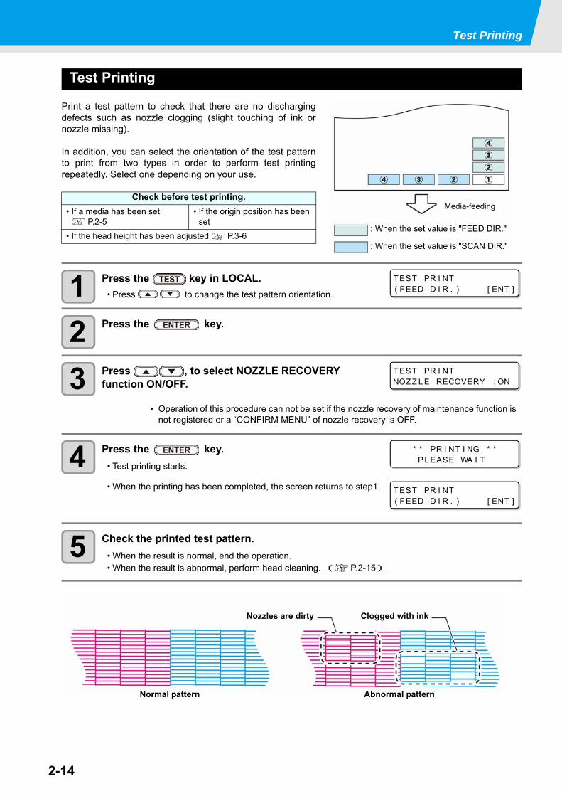
Test Printing
Print a test pattern to check that there are no dischargingdefects such as nozzle clogging (slight touching of ink ornozzle missing).
In addition, you can select the orientation of the test patternto print from two types in order to perform test printingrepeatedly. Select one depending on your use.
1 Press the key in LOCAL.• Press to change the test pattern orientation.
2 Press the key.
3 Press , to select NOZZLE RECOVERY function ON/OFF.
4 Press the key.• Test printing starts.
• When the printing has been completed, the screen returns to step1.
5 Check the printed test pattern.• When the result is normal, end the operation.• When the result is abnormal, perform head cleaning. ( P.2-15)
Check before test printing.• If a media has been set
P.2-5• If the origin position has been
set• If the head height has been adjusted P.3-6
• Operation of this procedure can not be set if the nozzle recovery of maintenance function is not registered or a “CONFIRM MENU” of nozzle recovery is OFF.
Media-feeding
: When the set value is "FEED DIR."
: When the set value is "SCAN DIR."
TEST PR I NT( FEED D I R . ) [ ENT ]
TEST PR I NTNOZ Z L E RECOVERY : ON
* * PR I NT I NG * *P L EASE WA I T
TEST PR I NT( FEED D I R . ) [ ENT ]
Abnormal pattern
Clogged with ink
Normal pattern
Nozzles are dirty
2-15
1
2
Basic O
perations
4
5
6
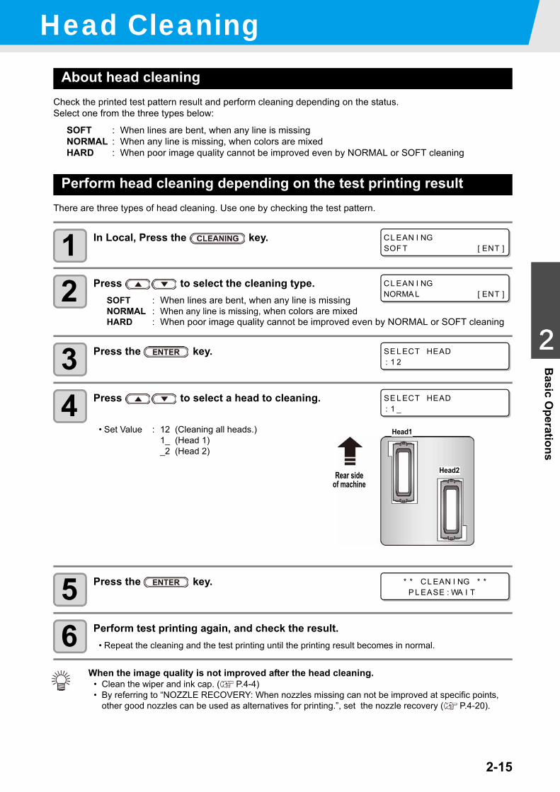
Head CleaningAbout head cleaning
Check the printed test pattern result and perform cleaning depending on the status.Select one from the three types below:
SOFT : When lines are bent, when any line is missingNORMAL : When any line is missing, when colors are mixedHARD : When poor image quality cannot be improved even by NORMAL or SOFT cleaning
Perform head cleaning depending on the test printing resultThere are three types of head cleaning. Use one by checking the test pattern.
1 In Local, Press the key.
2 Press to select the cleaning type.SOFT : When lines are bent, when any line is missingNORMAL : When any line is missing, when colors are mixedHARD : When poor image quality cannot be improved even by NORMAL or SOFT cleaning
3 Press the key.
4 Press to select a head to cleaning.
• Set Value : 12 (Cleaning all heads.)1_ (Head 1)_2 (Head 2)
5 Press the key.
6 Perform test printing again, and check the result.• Repeat the cleaning and the test printing until the printing result becomes in normal.
When the image quality is not improved after the head cleaning.• Clean the wiper and ink cap. ( P.4-4)• By referring to “NOZZLE RECOVERY: When nozzles missing can not be improved at specific points,
other good nozzles can be used as alternatives for printing.”, set the nozzle recovery ( P.4-20).
CL EAN I NGSOF T [ ENT ]
CL EAN I NGNORMA L [ ENT ]
SE L ECT HEAD: 1 2
SE L ECT HEAD: 1 _
Rear side of machine
Head1
Head2
* * CL EAN I NG * *P L EASE : WA I T
2-16
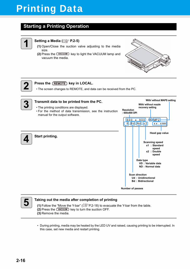
Printing DataStarting a Printing Operation
1 Setting a Media ( P.2-5)(1) Open/Close the suction valve adjusting to the media
size.(2) Press the key to light the VACUUM lamp and
vacuum the media.
2 Press the key in LOCAL.• The screen changes to REMOTE, and data can be received from the PC.
3 Transmit data to be printed from the PC.• The printing conditions are displayed.• For the method of data transmission, see the instruction
manual for the output software.
4 Start printing.
5 Taking out the media after completion of printing(1) Follow the “Move the Y-bar” ( P.2-18) to evacuate the Y-bar from the table.(2) Press the key to turn the suction OFF.(3) Remove the media.
• During printing, media may be heated by the LED UV and raised, causing printing to be interrupted. In this case, set new media and restart printing.
6 0 0 x 9 0 0 / R / MP 26 . B d . Nd . x 2 x x . xmm
Resolution : 600x900 DPI
Number of passes
Head gap value
Scan directionUd : UnidirectionalBd : Bidirectional
Data typeVD : Variable dataND : Normal data
Scanning speedx1 : Standard
speedx2 : Double
speed
With/ without nozzle recovery setting
With/ without MAPS setting
2-17
1
2
Basic O
perations
4
5
6
Printing Data
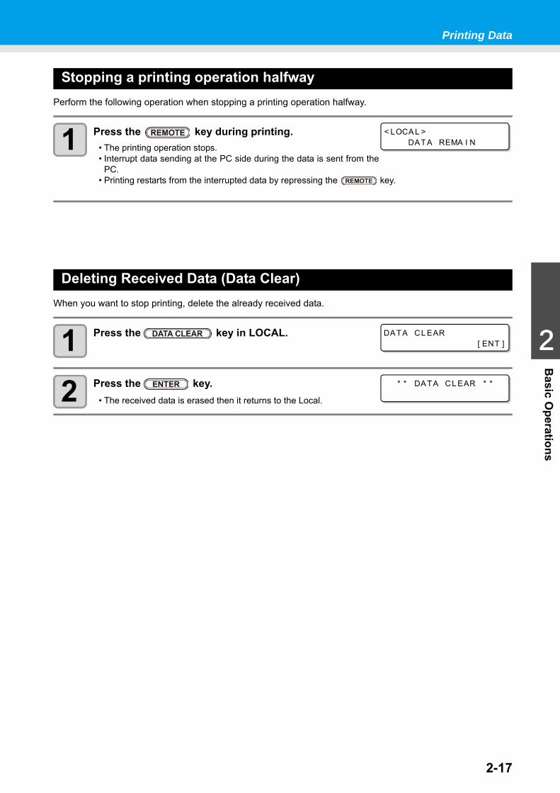
Stopping a printing operation halfwayPerform the following operation when stopping a printing operation halfway.
1 Press the key during printing.• The printing operation stops.• Interrupt data sending at the PC side during the data is sent from the
PC.• Printing restarts from the interrupted data by repressing the key.
Deleting Received Data (Data Clear)When you want to stop printing, delete the already received data.
1 Press the key in LOCAL.
2 Press the key.• The received data is erased then it returns to the Local.
< LOCA L >DATA REMA I N
DATA CL EAR[ ENT ]
* * DATA CL EAR * *
2-18
Printing Data
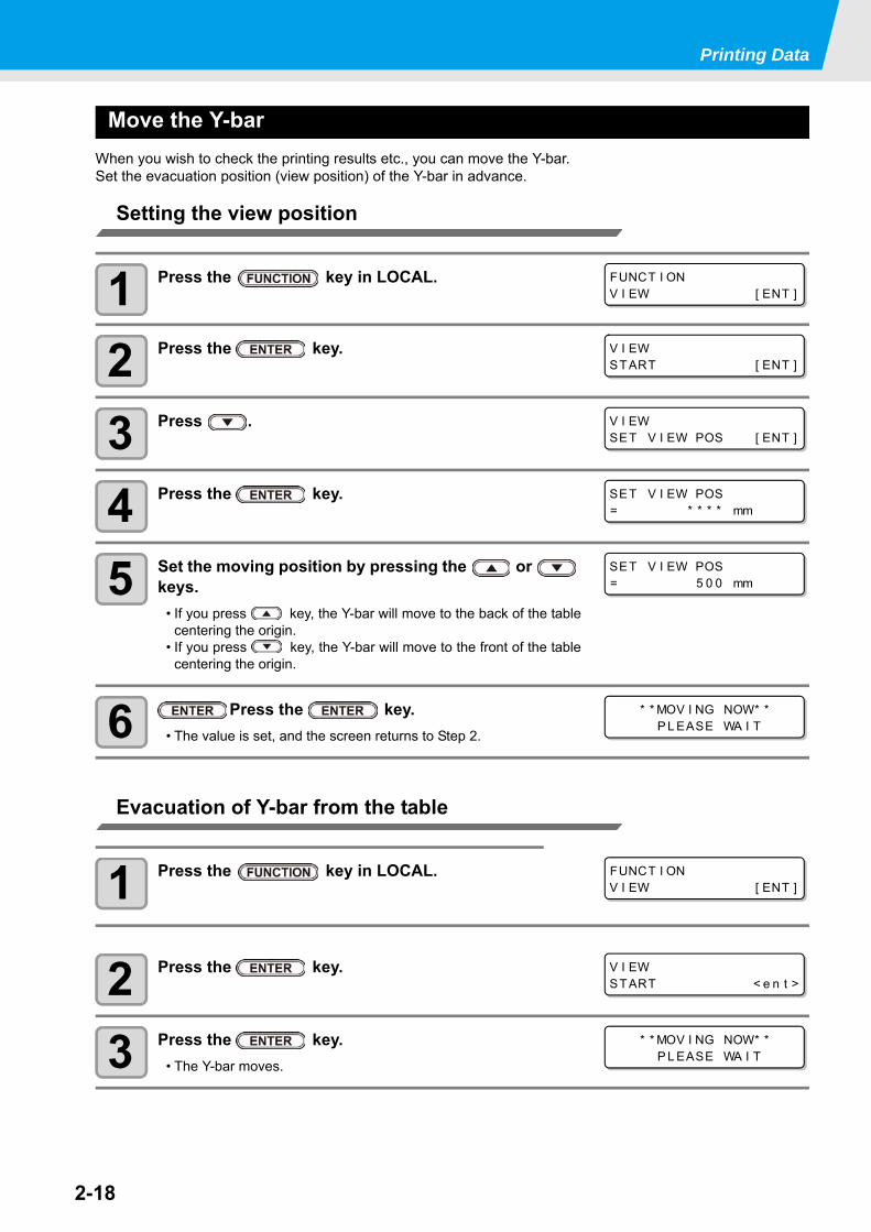
Move the Y-barWhen you wish to check the printing results etc., you can move the Y-bar.Set the evacuation position (view position) of the Y-bar in advance.
Setting the view position
1 Press the key in LOCAL.
2 Press the key.
3 Press .
4 Press the key.
5 Set the moving position by pressing the or keys.
• If you press key, the Y-bar will move to the back of the tablecentering the origin.
• If you press key, the Y-bar will move to the front of the tablecentering the origin.
6 Press the key.• The value is set, and the screen returns to Step 2.
Evacuation of Y-bar from the table
1 Press the key in LOCAL.
2 Press the key.
3 Press the key.• The Y-bar moves.
FUNCT I ONV I EW [ ENT ]
V I EWSTART [ ENT ]
V I EWSET V I EW POS [ ENT ]
SET V I EW POS= * * * * mm
SET V I EW POS= 5 0 0 mm
* * MOV I NG NOW* *P L EASE WA I T
FUNCT I ONV I EW [ ENT ]
V I EWSTART < e n t >
* * MOV I NG NOW* *P L EASE WA I T
This chapter
describes the operation procedures for using the machine more conveniently and eachsetting procedure.
Changing origin .............................................3-2Changing origin with JOG keys.................... 3-2Changing origin with FUNCTION menu ....... 3-3
Registering the thickness of the media .........3-4Register the thickness of the media manually....................................................... 3-4Adjust head gap with the or keys ............... 3-4Measuring the thickness of the media automatically ................................................ 3-5
Registering Head gap value ..........................3-6List of Functions ............................................3-7Correct the ink drop position for bidirectional printing ..........................................................3-8Setting Logical Seek ...................................3-10Setting UV mode .........................................3-11Perform setting to reduce stripes between passes .........................................................3-12
What is the MAPS Function? ..................... 3-12Setting MAPS1 Function ............................ 3-12Setting MAPS2 Function (4 color).............. 3-13Setting MAPS2 Function (4color + special color ink) ........................................ 3-14
Setting Work Change ..................................3-17Setting Ionizer .............................................3-18Setting Auto Cleaning .................................3-19Setting nozzle face cleaning time ................3-20Other Settings .............................................3-21Machine Settings .........................................3-22
Setting a AUTO Power-off ..........................3-22Setting Time................................................3-23Setting Units ...............................................3-24Setting a KEY BUZZER..............................3-25Setting a LANGUAGE.................................3-26
Initializing the Settings ................................3-27Confirming Machine Information .................3-28
Check the using status of the machine.......3-28Check the machine version information......3-29Displaying the Information of this machine.3-30
Chapter 3Extended Functions
3-2
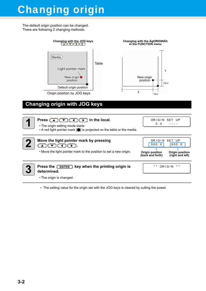
Changing origin The default origin position can be changed.There are following 2 changing methods.
Changing origin with JOG keys
1 Press in the local.• The origin setting mode starts• A red light pointer mark [] is projected on the table or the media.
2 Move the light pointer mark by pressing .
• Move the light pointer mark to the position to set a new origin.
3 Press the key when the printing origin is determined.
• The origin is changed.
• The setting value for the origin set with the JOG keys is cleared by cutting the power.
Changing with the JOG keys Changing with the ÅgORIGINÅh in the FUNCTION menu
OR I G I N SET UP0 . 0 - - - -
OR I G I N SET UP5 0 0 . 0 6 0 0 . 0
Origin position (back and forth)
Origin position (right and left)
* * OR I G I N * *
3-3
1
1
3
Convenient use
5
6
Changing origin
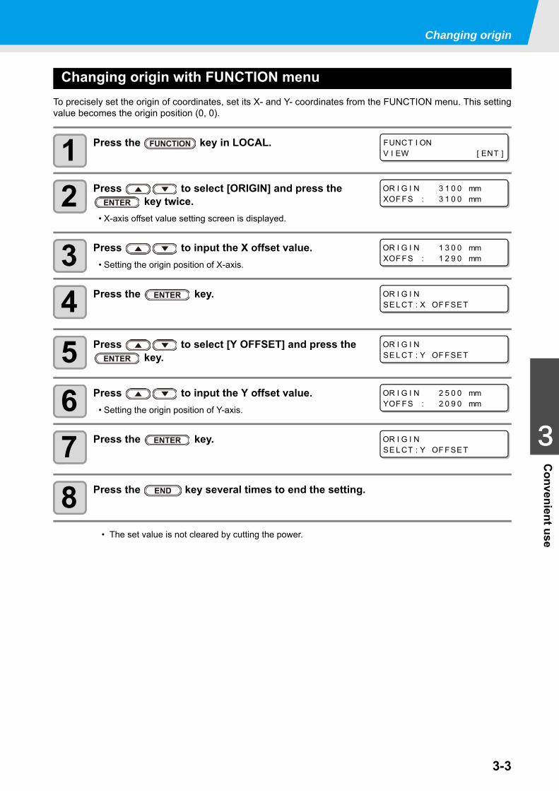
Changing origin with FUNCTION menuTo precisely set the origin of coordinates, set its X- and Y- coordinates from the FUNCTION menu. This settingvalue becomes the origin position (0, 0).
1 Press the key in LOCAL.
2 Press to select [ORIGIN] and press the key twice.
• X-axis offset value setting screen is displayed.
3 Press to input the X offset value.• Setting the origin position of X-axis.
4 Press the key.
5 Press to select [Y OFFSET] and press the key.
6 Press to input the Y offset value.• Setting the origin position of Y-axis.
7 Press the key.
8 Press the key several times to end the setting.
• The set value is not cleared by cutting the power.
FUNCT I ONV I EW [ ENT ]
OR I G I N 3 1 0 0 mmXOF FS : 3 1 0 0 mm
OR I G I N 1 3 0 0 mmXOF FS : 1 2 9 0 mm
OR I G I NSE LCT : X OF FSET
OR I G I NSE LCT : Y OF FSET
OR I G I N 2 5 0 0 mmYOF FS : 2 0 9 0 mm
OR I G I NSE LCT : Y OF FSET
3-4
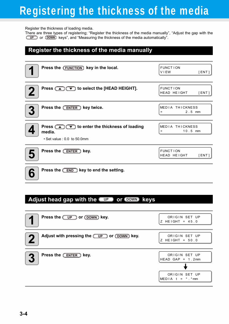
Registering the thickness of the mediaRegister the thickness of loading media.There are three types of registering; “Register the thickness of the media manually”, “Adjust the gap with the
or keys”, and “Measuring the thickness of the media automatically”.
Register the thickness of the media manually
1 Press the key in the local.
2 Press to select the [HEAD HEIGHT].
3 Press the key twice.
4 Press to enter the thickness of loading media.
• Set value : 0.0 to 50.0mm
5 Press the key.
6 Press the key to end the setting.
Adjust head gap with the or keys
1 Press the or key.
2 Adjust with pressing the or key.
3 Press the key.
FUNCT I ONV I EW [ ENT ]
FUNCT I ONHEAD HE I GHT [ ENT ]
MED I A TH I CKNESS= 2 . 5 mm
MED I A TH I CKNESS= 1 0 . 5 mm
FUNCT I ONHEAD HE I GHT [ ENT ]
OR I G I N SET UPZ HE I GHT = 4 5 . 0
OR I G I N SET UPZ HE I GHT = 5 0 . 0
OR I G I N SET UPHEAD GAP = 1 . 2mm
OR I G I N SET UPMED I A t = * . * mm
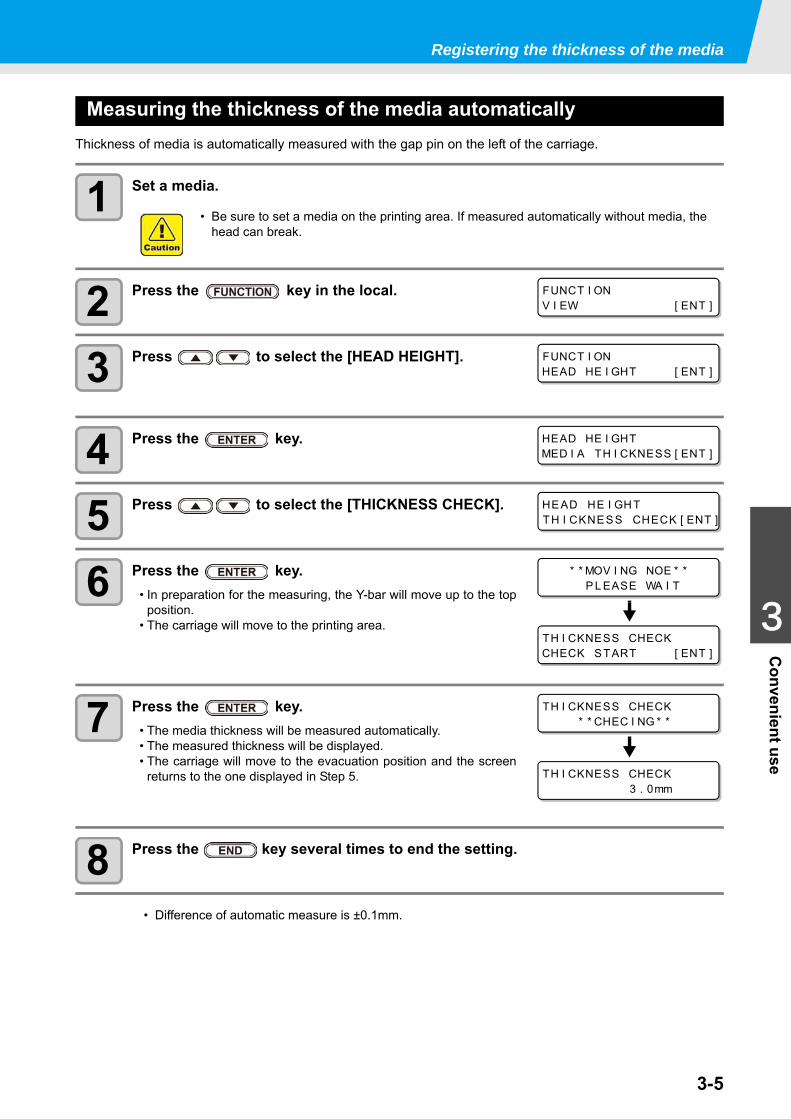
3-5
1
1
3
Convenient use
5
6
Registering the thickness of the media
Measuring the thickness of the media automaticallyThickness of media is automatically measured with the gap pin on the left of the carriage.
1 Set a media.
2 Press the key in the local.
3 Press to select the [HEAD HEIGHT].
4 Press the key.
5 Press to select the [THICKNESS CHECK].
6 Press the key.• In preparation for the measuring, the Y-bar will move up to the top
position.• The carriage will move to the printing area.
7 Press the key.• The media thickness will be measured automatically.• The measured thickness will be displayed.• The carriage will move to the evacuation position and the screen
returns to the one displayed in Step 5.
8 Press the key several times to end the setting.
• Be sure to set a media on the printing area. If measured automatically without media, the head can break.
• Difference of automatic measure is ±0.1mm.
FUNCT I ONV I EW [ ENT ]
FUNCT I ONHEAD HE I GHT [ ENT ]
HEAD HE I GHTMED I A TH I CKNESS [ ENT ]
HE AD HE I GH TTH I CKNE SS CHECK [ ENT ]
* * MOV I NG NOE * *P L EASE WA I T
TH I CKNESS CHECKCHECK START [ ENT ]
TH I CKNESS CHECK* * CHEC I NG * *
TH I CKNESS CHECK3 . 0mm
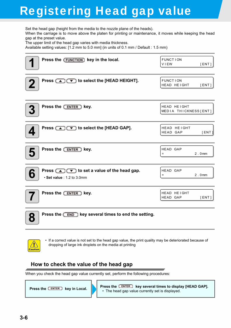
3-6
Registering Head gap valueSet the head gap (height from the media to the nozzle plane of the heads).When the carriage is to move above the platen for printing or maintenance, it moves while keeping the headgap at the preset value.The upper limit of the head gap varies with media thickness.Available setting values: [1.2 mm to 5.0 mm] (in units of 0.1 mm / Default : 1.5 mm)
1 Press the key in the local.
2 Press to select the [HEAD HEIGHT].
3 Press the key.
4 Press to select the [HEAD GAP].
5 Press the key.
6 Press to set a value of the head gap.• Set value : 1.2 to 3.0mm
7 Press the key.
8 Press the key several times to end the setting.
How to check the value of the head gapWhen you check the head gap value currently set, perform the following procedures:
• If a correct value is not set to the head gap value, the print quality may be deteriorated because of dropping of large ink droplets on the media at printing
Press the key in Local. Press the key several times to display [HEAD GAP].• The head gap value currently set is displayed.
FUNCT I ONV I EW [ ENT ]
FUNCT I ONHEAD HE I GHT [ ENT ]
HEAD HE I GHTMED I A TH I CKNESS [ ENT ]
HEAD HE I GHTHEAD GAP [ ENT ]
HEAD GAP= 2 . 0mm
HEAD GAP= 2 . 0mm
HEAD HE I GHTHEAD GAP [ ENT ]
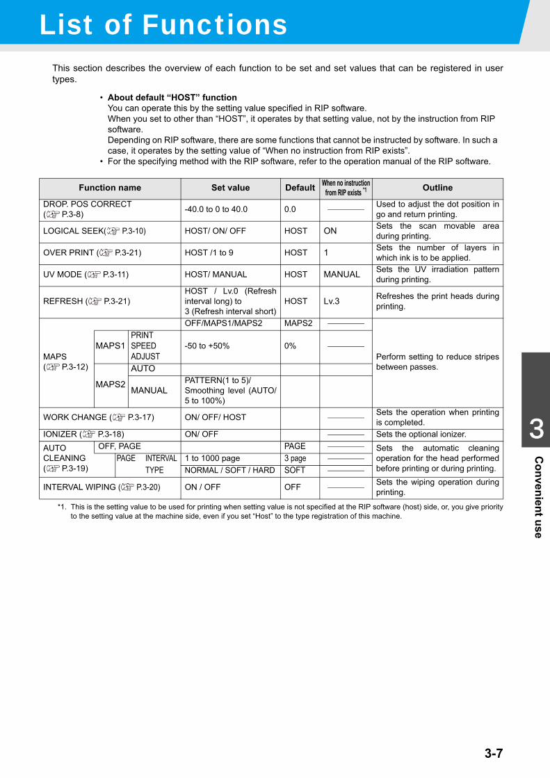
3-7
1
1
3
Convenient use
5
6
List of FunctionsThis section describes the overview of each function to be set and set values that can be registered in usertypes.
• About default “HOST” functionYou can operate this by the setting value specified in RIP software.When you set to other than “HOST”, it operates by that setting value, not by the instruction from RIP software.Depending on RIP software, there are some functions that cannot be instructed by software. In such a case, it operates by the setting value of “When no instruction from RIP exists”.
• For the specifying method with the RIP software, refer to the operation manual of the RIP software.
Function name Set value Default When no instruction from RIP exists *1
*1. This is the setting value to be used for printing when setting value is not specified at the RIP software (host) side, or, you give priorityto the setting value at the machine side, even if you set “Host” to the type registration of this machine.
Outline
DROP. POS CORRECT ( P.3-8) -40.0 to 0 to 40.0 0.0 Used to adjust the dot position in
go and return printing.
LOGICAL SEEK( P.3-10) HOST/ ON/ OFF HOST ON Sets the scan movable areaduring printing.
OVER PRINT ( P.3-21) HOST /1 to 9 HOST 1 Sets the number of layers inwhich ink is to be applied.
UV MODE ( P.3-11) HOST/ MANUAL HOST MANUAL Sets the UV irradiation patternduring printing.
REFRESH ( P.3-21)HOST / Lv.0 (Refreshinterval long) to 3 (Refresh interval short)
HOST Lv.3 Refreshes the print heads duringprinting.
MAPS( P.3-12)
OFF/MAPS1/MAPS2 MAPS2
Perform setting to reduce stripesbetween passes.
MAPS1PRINT SPEED ADJUST
-50 to +50% 0%
MAPS2
AUTO
MANUALPATTERN(1 to 5)/Smoothing level (AUTO/5 to 100%)
WORK CHANGE ( P.3-17) ON/ OFF/ HOST Sets the operation when printingis completed.
IONIZER ( P.3-18) ON/ OFF Sets the optional ionizer.AUTOCLEANING( P.3-19)
OFF, PAGE PAGE Sets the automatic cleaningoperation for the head performedbefore printing or during printing.
PAGE INTERVAL 1 to 1000 page 3 page TYPE NORMAL / SOFT / HARD SOFT
INTERVAL WIPING ( P.3-20) ON / OFF OFF Sets the wiping operation duringprinting.
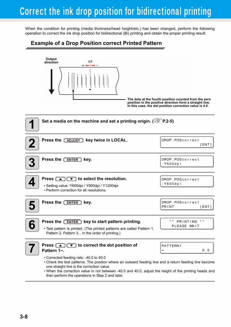
3-8
Correct the ink drop position for bidirectional printingWhen the condition for printing (media thickness/head height/etc.) has been changed, perform the followingoperation to correct the ink drop position for bidirectional (Bi) printing and obtain the proper printing result.
Example of a Drop Position correct Printed Pattern
1 Set a media on the machine and set a printing origin. ( P.2-5)
2 Press the key twice in LOCAL.
3 Press the key.
4 Press to select the resolution.• Setting value: Y600dpi / Y900dpi / Y1200dpi• Perform correction for all resolutions.
5 Press the key.
6 Press the key to start pattern printing.• Test pattern is printed. (The printed patterns are called Pattern 1,
Pattern 2, Pattern 3... in the order of printing.)
7 Press to correct the dot position of Pattern 1~.
• Corrected feeding rate: -40.0 to 40.0• Check the test patterns. The position where an outward feeding line and a return feeding line become
one straight line is the correction value.• When the correction value in not between -40.0 and 40.0, adjust the height of the printing heads and
then perform the operations in Step 2 and later.
The dots at the fourth position counted from the zero position in the positive direction form a straight line.In this case, the dot position correction value is 4.0.
Output direction
DROP . POS c o r r e c t[ ENT ]
DROP . POS c o r r e c t: Y 6 0 0 d p i
DROP . POS c o r r e c t: Y 6 0 0 d p i
DROP . POS c o r r e c tPR I NT [ ENT ]
* * PR I NT I NG * *P L EASE WA I T
PAT TERN1= 0 . 0
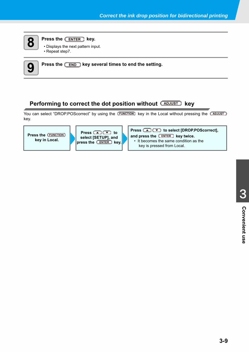
3-9
1
1
3
Convenient use
5
6
Correct the ink drop position for bidirectional printing
8 Press the key.• Displays the next pattern input.• Repeat step7.
9 Press the key several times to end the setting.
Performing to correct the dot position without keyYou can select “DROP.POScorrect” by using the key in the Local without pressing the key.
Press the key in Local.
Press to select [SETUP], and
press the key.
Press to select [DROP.POScorrect], and press the key twice.
• It becomes the same condition as the key is pressed from Local.
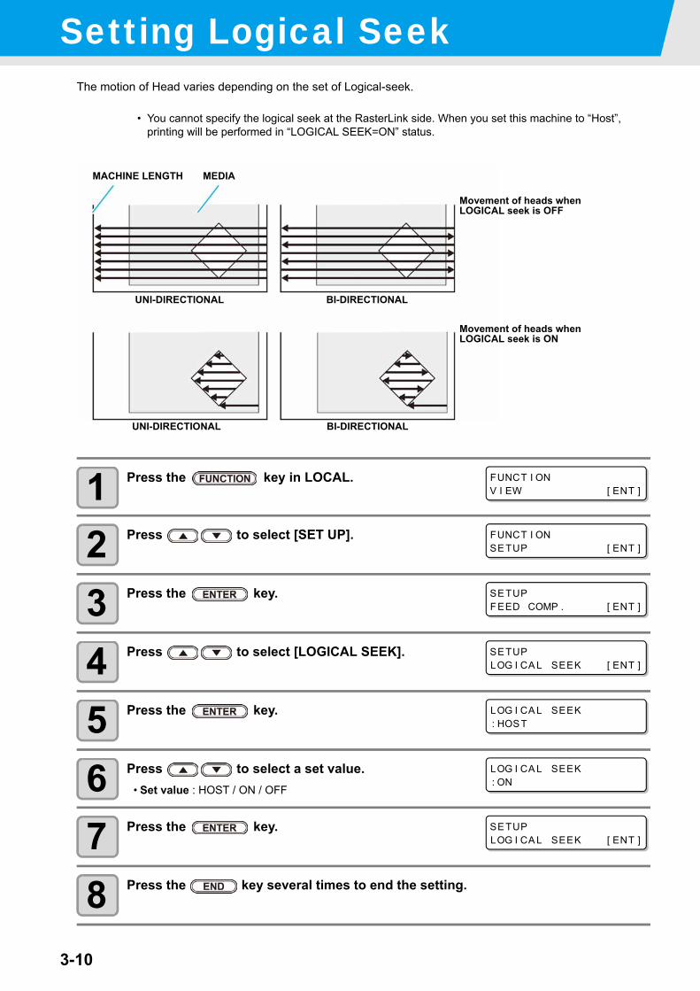
3-10
Setting Logical SeekThe motion of Head varies depending on the set of Logical-seek.
1 Press the key in LOCAL.
2 Press to select [SET UP].
3 Press the key.
4 Press to select [LOGICAL SEEK].
5 Press the key.
6 Press to select a set value.• Set value : HOST / ON / OFF
7 Press the key.
8 Press the key several times to end the setting.
• You cannot specify the logical seek at the RasterLink side. When you set this machine to “Host”, printing will be performed in “LOGICAL SEEK=ON” status.
UNI-DIRECTIONAL BI-DIRECTIONAL
Movement of heads when LOGICAL seek is OFF
Movement of heads when LOGICAL seek is ON
UNI-DIRECTIONAL BI-DIRECTIONAL
MACHINE LENGTH MEDIA
FUNCT I ONV I EW [ ENT ]
FUNCT I ONSETUP [ ENT ]
SETUPFEED COMP . [ ENT ]
SETUPLOG I CA L SEEK [ ENT ]
LOG I CA L SEEK: HOST
LOG I CA L SEEK: ON
SETUPLOG I CA L SEEK [ ENT ]
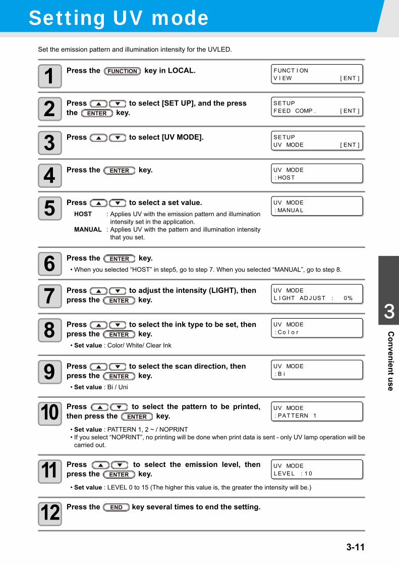
3-11
1
1
3
Convenient use
5
6
Setting UV modeSet the emission pattern and illumination intensity for the UVLED.
1 Press the key in LOCAL.
2 Press to select [SET UP], and the press the key.
3 Press to select [UV MODE].
4 Press the key.
5 Press to select a set value.HOST : Applies UV with the emission pattern and illumination
intensity set in the application.MANUAL : Applies UV with the pattern and illumination intensity
that you set.
6 Press the key.• When you selected “HOST” in step5, go to step 7. When you selected “MANUAL”, go to step 8.
7 Press to adjust the intensity (LIGHT), then press the key.
8 Press to select the ink type to be set, then press the key.
• Set value : Color/ White/ Clear Ink
9 Press to select the scan direction, then press the key.
• Set value : Bi / Uni
10 Press to select the pattern to be printed,then press the key.
• Set value : PATTERN 1, 2 ~ / NOPRINT• If you select “NOPRINT”, no printing will be done when print data is sent - only UV lamp operation will be
carried out.
11 Press to select the emission level, thenpress the key.
• Set value : LEVEL 0 to 15 (The higher this value is, the greater the intensity will be.)
12 Press the key several times to end the setting.
FUNCT I ONV I EW [ ENT ]
SETUPFEED COMP . [ ENT ]
SETUPUV MODE [ ENT ]
UV MODE: HOST
UV MODE: MANUA L
UV MODEL I GHT AD J UST : 0%
UV MODE: Co l o r
UV MODE: B i
UV MODE: PAT TERN 1
UV MODEL EVE L : 1 0
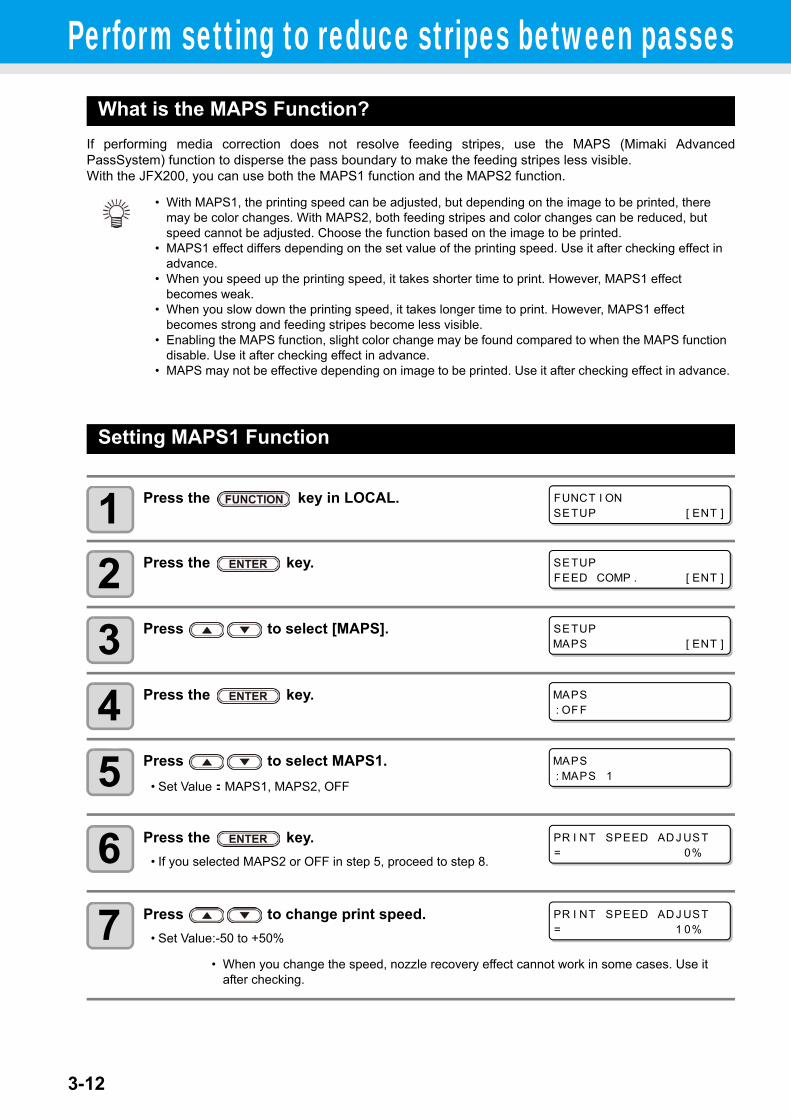
3-12
Perform setting to reduce stripes between passesWhat is the MAPS Function?
If performing media correction does not resolve feeding stripes, use the MAPS (Mimaki AdvancedPassSystem) function to disperse the pass boundary to make the feeding stripes less visible.With the JFX200, you can use both the MAPS1 function and the MAPS2 function.
Setting MAPS1 Function
1 Press the key in LOCAL.
2 Press the key.
3 Press to select [MAPS].
4 Press the key.
5 Press to select MAPS1.• Set Value:MAPS1, MAPS2, OFF
6 Press the key.• If you selected MAPS2 or OFF in step 5, proceed to step 8.
7 Press to change print speed.• Set Value:-50 to +50%
• With MAPS1, the printing speed can be adjusted, but depending on the image to be printed, there may be color changes. With MAPS2, both feeding stripes and color changes can be reduced, but speed cannot be adjusted. Choose the function based on the image to be printed.
• MAPS1 effect differs depending on the set value of the printing speed. Use it after checking effect in advance.
• When you speed up the printing speed, it takes shorter time to print. However, MAPS1 effect becomes weak.
• When you slow down the printing speed, it takes longer time to print. However, MAPS1 effect becomes strong and feeding stripes become less visible.
• Enabling the MAPS function, slight color change may be found compared to when the MAPS function disable. Use it after checking effect in advance.
• MAPS may not be effective depending on image to be printed. Use it after checking effect in advance.
• When you change the speed, nozzle recovery effect cannot work in some cases. Use it after checking.
FUNCT I ONSETUP [ ENT ]
SETUPFEED COMP . [ ENT ]
SETUPMAPS [ ENT ]
MAPS: OF F
MAPS: MAPS 1
PR I NT SPEED AD J UST= 0%
PR I NT SPEED AD J UST= 1 0%
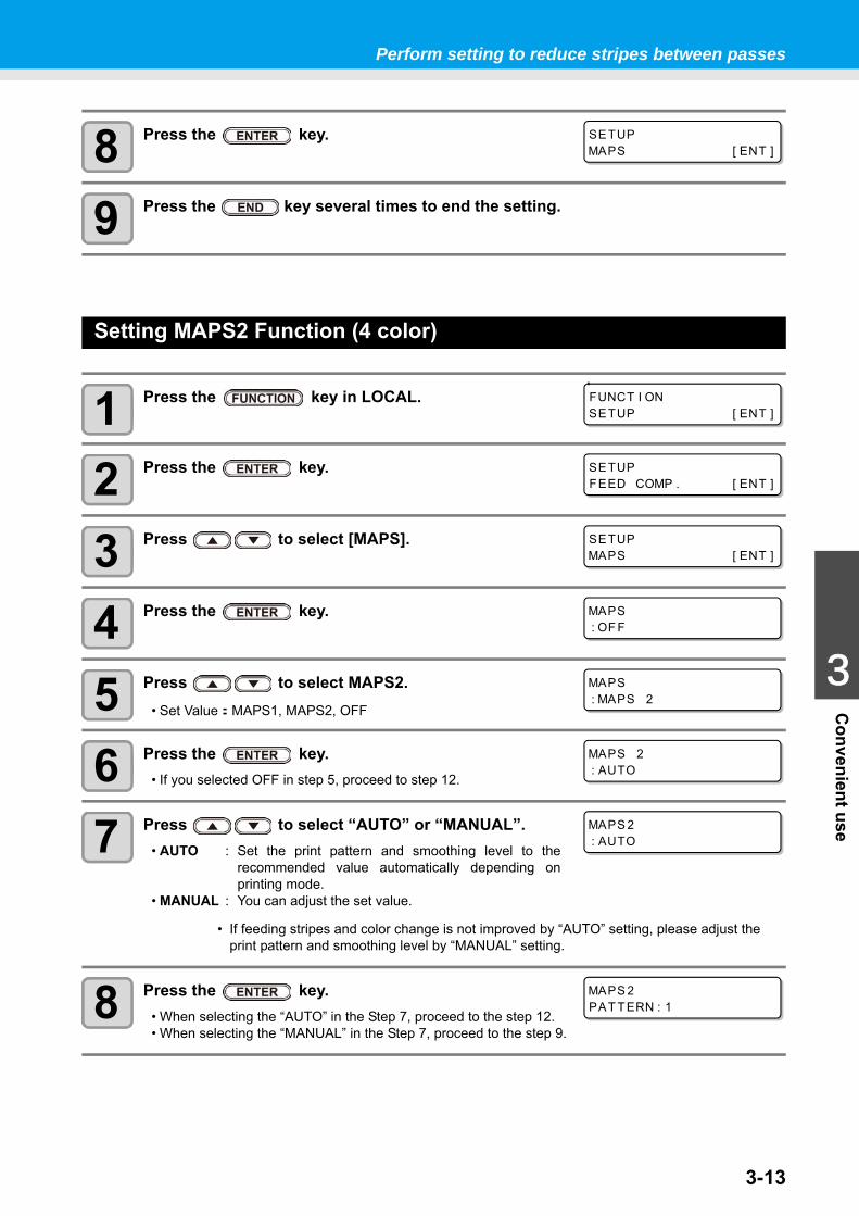
3-13
1
1
3
Convenient use
5
6
Perform setting to reduce stripes between passes
8 Press the key.
9 Press the key several times to end the setting.
Setting MAPS2 Function (4 color)
1 Press the key in LOCAL.
2 Press the key.
3 Press to select [MAPS].
4 Press the key.
5 Press to select MAPS2.• Set Value:MAPS1, MAPS2, OFF
6 Press the key.• If you selected OFF in step 5, proceed to step 12.
7 Press to select “AUTO” or “MANUAL”.• AUTO : Set the print pattern and smoothing level to the
recommended value automatically depending onprinting mode.
• MANUAL : You can adjust the set value.
8 Press the key.• When selecting the “AUTO” in the Step 7, proceed to the step 12.• When selecting the “MANUAL” in the Step 7, proceed to the step 9.
• If feeding stripes and color change is not improved by “AUTO” setting, please adjust the print pattern and smoothing level by “MANUAL” setting.
SETUPMAPS [ ENT ]
FUNCT I ONSETUP [ ENT ]
SETUPFEED COMP . [ ENT ]
SETUPMAPS [ ENT ]
MAPS: OF F
MAPS: MAPS 2
MAPS 2: AUTO
MAPS 2: AUTO
MAPS 2PAT TERN : 1
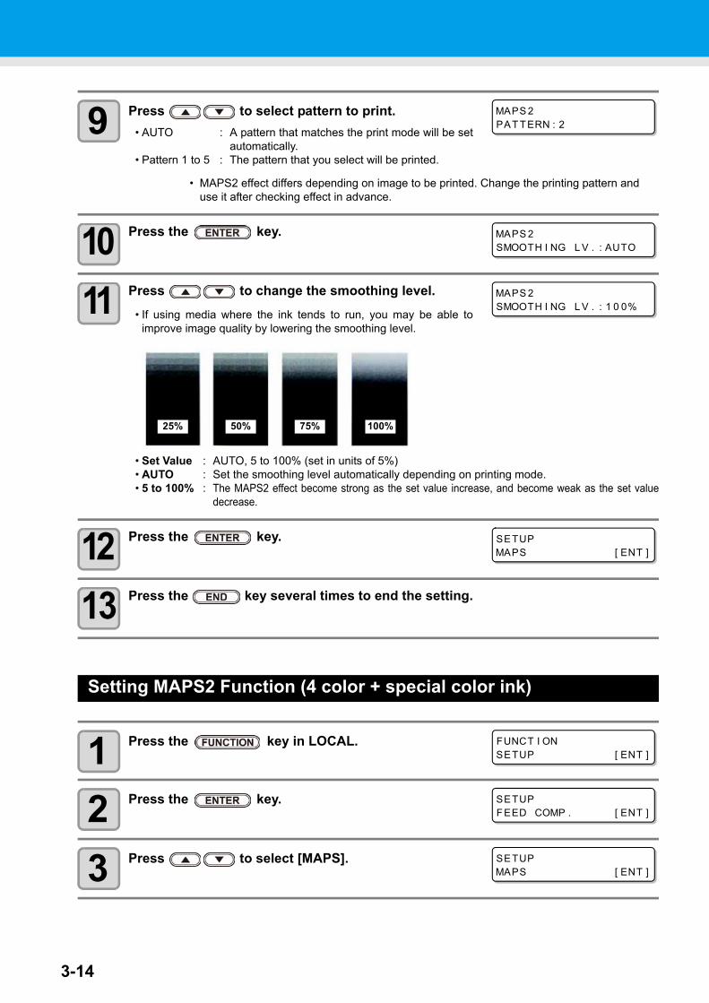
3-14
9 Press to select pattern to print.• AUTO : A pattern that matches the print mode will be set
automatically.• Pattern 1 to 5 : The pattern that you select will be printed.
10 Press the key.
11 Press to change the smoothing level.• If using media where the ink tends to run, you may be able to
improve image quality by lowering the smoothing level.
• Set Value : AUTO, 5 to 100% (set in units of 5%)• AUTO : Set the smoothing level automatically depending on printing mode.• 5 to 100% : The MAPS2 effect become strong as the set value increase, and become weak as the set value
decrease.
12 Press the key.
13 Press the key several times to end the setting.
Setting MAPS2 Function (4 color + special color ink)
1 Press the key in LOCAL.
2 Press the key.
3 Press to select [MAPS].
• MAPS2 effect differs depending on image to be printed. Change the printing pattern and use it after checking effect in advance.
MAPS 2PAT TERN : 2
MAPS 2SMOOTH I NG L V . : AUTO
MAPS 2SMOOTH I NG L V . : 1 0 0%
25% 50% 75% 100%
SETUPMAPS [ ENT ]
FUNCT I ONSETUP [ ENT ]
SETUPFEED COMP . [ ENT ]
SETUPMAPS [ ENT ]
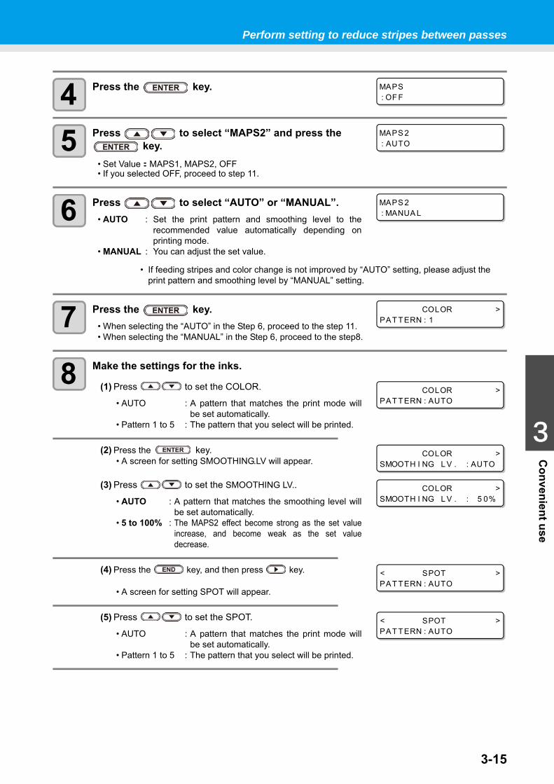
3-15
1
1
3
Convenient use
5
6
Perform setting to reduce stripes between passes
4 Press the key.
5 Press to select “MAPS2” and press the key.
• Set Value:MAPS1, MAPS2, OFF• If you selected OFF, proceed to step 11.
6 Press to select “AUTO” or “MANUAL”.• AUTO : Set the print pattern and smoothing level to the
recommended value automatically depending onprinting mode.
• MANUAL : You can adjust the set value.
7 Press the key.• When selecting the “AUTO” in the Step 6, proceed to the step 11.• When selecting the “MANUAL” in the Step 6, proceed to the step8.
8 Make the settings for the inks.
(1) Press to set the COLOR.
• AUTO : A pattern that matches the print mode willbe set automatically.
• Pattern 1 to 5 : The pattern that you select will be printed.
(2) Press the key.• A screen for setting SMOOTHING.LV will appear.
(3) Press to set the SMOOTHING LV..
• AUTO : A pattern that matches the smoothing level willbe set automatically.
• 5 to 100% : The MAPS2 effect become strong as the set valueincrease, and become weak as the set valuedecrease.
(4) Press the key, and then press key.
• A screen for setting SPOT will appear.
(5) Press to set the SPOT.
• AUTO : A pattern that matches the print mode willbe set automatically.
• Pattern 1 to 5 : The pattern that you select will be printed.
• If feeding stripes and color change is not improved by “AUTO” setting, please adjust the print pattern and smoothing level by “MANUAL” setting.
MAPS: OF F
MAPS 2: AUTO
MAPS 2: MANUA L
COLOR >PAT TERN : 1
COLOR >PAT TERN : AUTO
COLOR >SMOOTH I NG L V . : AUTO
COLOR >SMOOTH I NG L V . : 5 0%
< SPOT >PAT TERN : AUTO
< SPOT >PAT TERN : AUTO
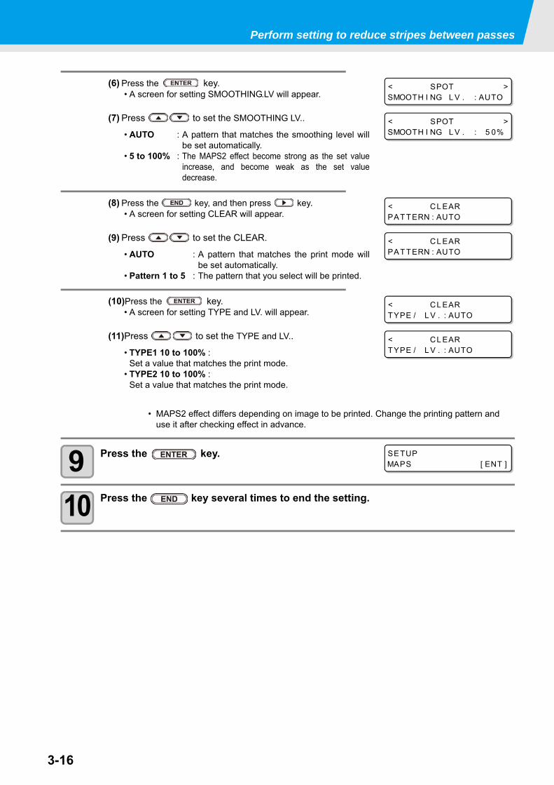
3-16
Perform setting to reduce stripes between passes
(6) Press the key.• A screen for setting SMOOTHING.LV will appear.
(7) Press to set the SMOOTHING LV..
• AUTO : A pattern that matches the smoothing level willbe set automatically.
• 5 to 100% : The MAPS2 effect become strong as the set valueincrease, and become weak as the set valuedecrease.
(8) Press the key, and then press key.• A screen for setting CLEAR will appear.
(9) Press to set the CLEAR.
• AUTO : A pattern that matches the print mode willbe set automatically.
• Pattern 1 to 5 : The pattern that you select will be printed.
(10)Press the key.• A screen for setting TYPE and LV. will appear.
(11)Press to set the TYPE and LV..
• TYPE1 10 to 100% :Set a value that matches the print mode.
• TYPE2 10 to 100% :Set a value that matches the print mode.
9 Press the key.
10 Press the key several times to end the setting.
• MAPS2 effect differs depending on image to be printed. Change the printing pattern and use it after checking effect in advance.
< SPOT >SMOOTH I NG L V . : AUTO
< SPOT >SMOOTH I NG L V . : 5 0%
< CL EARPAT TERN : AUTO
< CL EARPAT TERN : AUTO
< CL EARTYPE / L V . : AUTO
< CL EARTYPE / L V . : AUTO
SETUPMAPS [ ENT ]
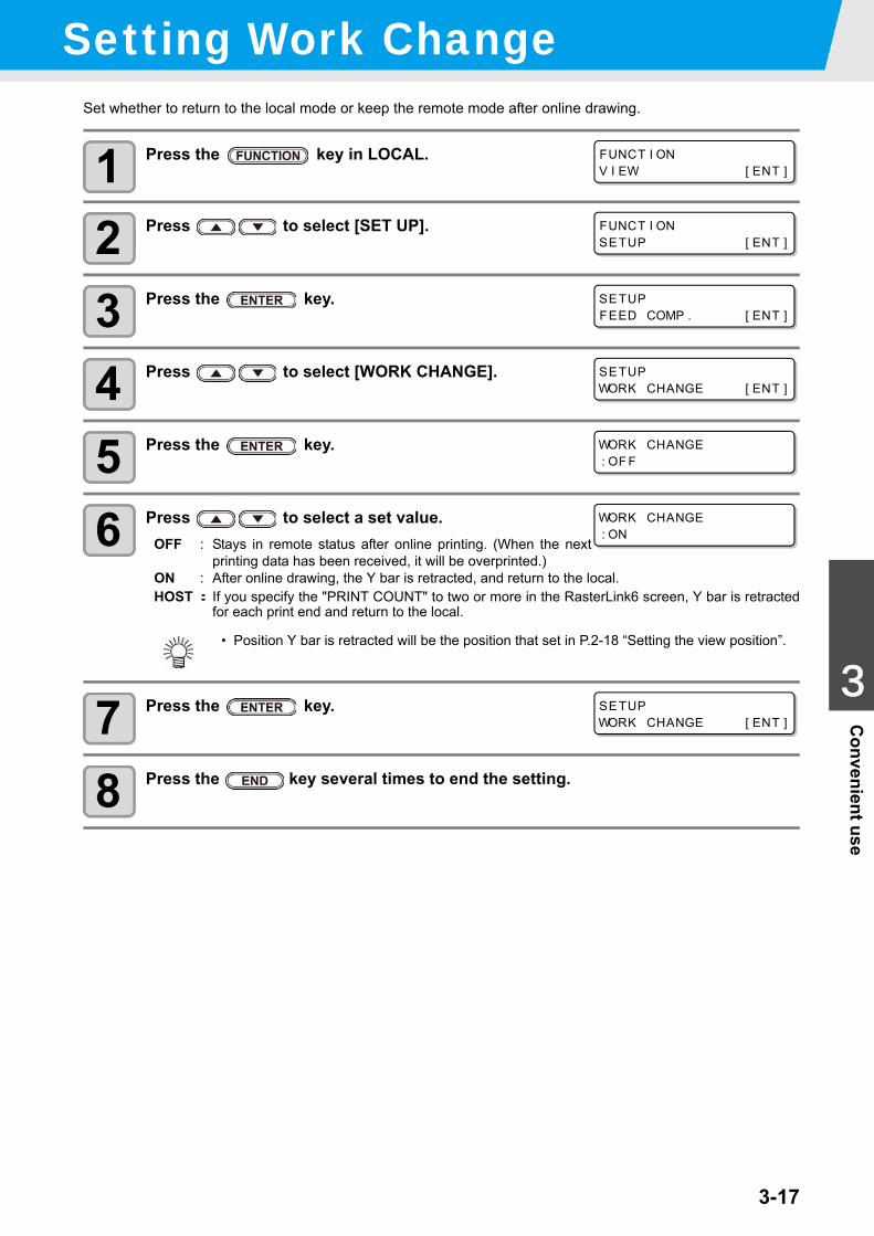
3-17
1
1
3
Convenient use
5
6
Setting Work ChangeSet whether to return to the local mode or keep the remote mode after online drawing.
1 Press the key in LOCAL.
2 Press to select [SET UP].
3 Press the key.
4 Press to select [WORK CHANGE].
5 Press the key.
6 Press to select a set value.OFF : Stays in remote status after online printing. (When the next
printing data has been received, it will be overprinted.)ON : After online drawing, the Y bar is retracted, and return to the local.HOST: If you specify the "PRINT COUNT" to two or more in the RasterLink6 screen, Y bar is retracted
for each print end and return to the local.
7 Press the key.
8 Press the key several times to end the setting.
• Position Y bar is retracted will be the position that set in P.2-18 “Setting the view position”.
FUNCT I ONV I EW [ ENT ]
FUNCT I ONSETUP [ ENT ]
SETUPFEED COMP . [ ENT ]
SETUPWORK CHANGE [ ENT ]
WORK CHANGE: OF F
WORK CHANGE: ON
SETUPWORK CHANGE [ ENT ]
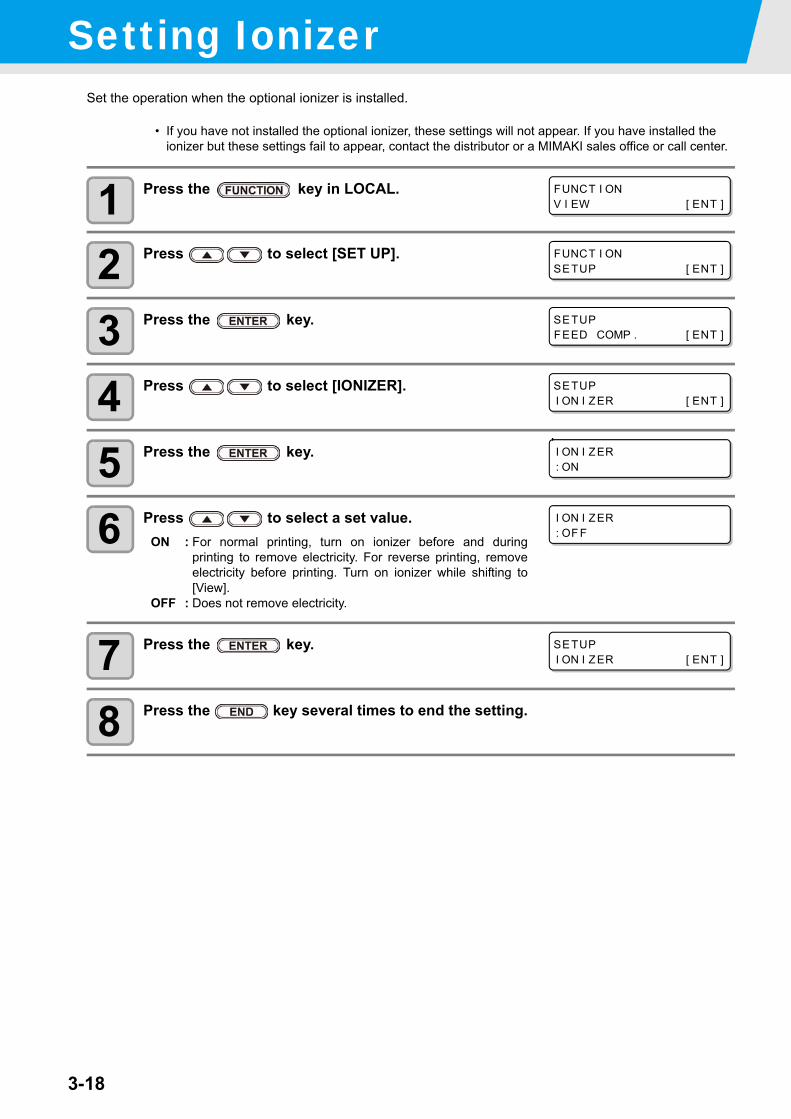
3-18
Setting IonizerSet the operation when the optional ionizer is installed.
1 Press the key in LOCAL.
2 Press to select [SET UP].
3 Press the key.
4 Press to select [IONIZER].
5 Press the key.
6 Press to select a set value.ON : For normal printing, turn on ionizer before and during
printing to remove electricity. For reverse printing, removeelectricity before printing. Turn on ionizer while shifting to[View].
OFF : Does not remove electricity.
7 Press the key.
8 Press the key several times to end the setting.
• If you have not installed the optional ionizer, these settings will not appear. If you have installed the ionizer but these settings fail to appear, contact the distributor or a MIMAKI sales office or call center.
FUNCT I ONV I EW [ ENT ]
FUNCT I ONSETUP [ ENT ]
SETUPFEED COMP . [ ENT ]
SETUPI ON I ZER [ ENT ]
I ON I ZER: ON
I ON I ZER: OF F
SETUPI ON I ZER [ ENT ]
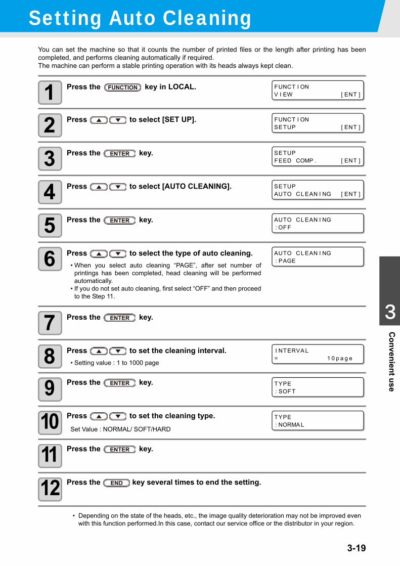
3-19
1
1
3
Convenient use
5
6
Setting Auto CleaningYou can set the machine so that it counts the number of printed files or the length after printing has beencompleted, and performs cleaning automatically if required.The machine can perform a stable printing operation with its heads always kept clean.
1 Press the key in LOCAL.
2 Press to select [SET UP].
3 Press the key.
4 Press to select [AUTO CLEANING].
5 Press the key.
6 Press to select the type of auto cleaning.• When you select auto cleaning “PAGE”, after set number of
printings has been completed, head cleaning will be performedautomatically.
• If you do not set auto cleaning, first select “OFF” and then proceedto the Step 11.
7 Press the key.
8 Press to set the cleaning interval.• Setting value : 1 to 1000 page
9 Press the key.
10 Press to set the cleaning type.Set Value : NORMAL/ SOFT/HARD
11 Press the key.
12 Press the key several times to end the setting.
• Depending on the state of the heads, etc., the image quality deterioration may not be improved even with this function performed.In this case, contact our service office or the distributor in your region.
FUNCT I ONV I EW [ ENT ]
FUNCT I ONSETUP [ ENT ]
SETUPFEED COMP . [ ENT ]
SETUPAUTO CL EAN I NG [ ENT ]
AUTO CL EAN I NG: OF F
AUTO CL EAN I NG: PAGE
I NTERVA L= 1 0 p a g e
TYPE: SOF T
TYPE: NORMA L
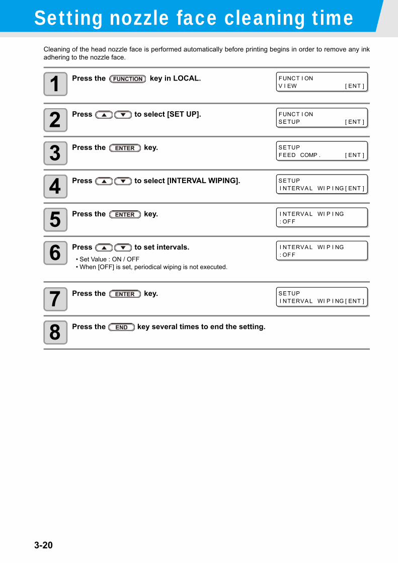
3-20
Setting nozzle face cleaning timeCleaning of the head nozzle face is performed automatically before printing begins in order to remove any inkadhering to the nozzle face.
1 Press the key in LOCAL.
2 Press to select [SET UP].
3 Press the key.
4 Press to select [INTERVAL WIPING].
5 Press the key.
6 Press to set intervals.• Set Value : ON / OFF• When [OFF] is set, periodical wiping is not executed.
7 Press the key.
8 Press the key several times to end the setting.
FUNCT I ONV I EW [ ENT ]
FUNCT I ONSETUP [ ENT ]
SETUPFEED COMP . [ ENT ]
SETUPI NTERVA L WI P I NG [ ENT ]
I NTERVA L WI P I NG: OF F
I NTERVA L WI P I NG: OF F
SETUPI NTERVA L WI P I NG [ ENT ]
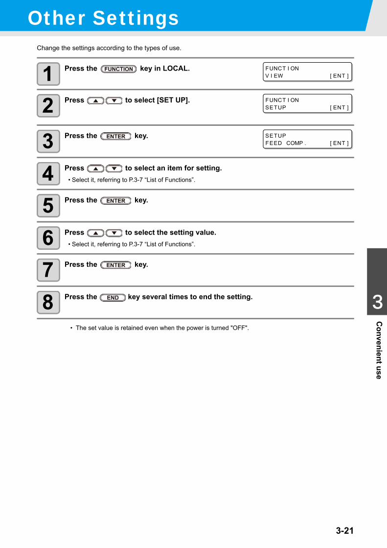
3-21
1
1
3
Convenient use
5
6
Other SettingsChange the settings according to the types of use.
1 Press the key in LOCAL.
2 Press to select [SET UP].
3 Press the key.
4 Press to select an item for setting.• Select it, referring to P.3-7 “List of Functions”.
5 Press the key.
6 Press to select the setting value.• Select it, referring to P.3-7 “List of Functions”.
7 Press the key.
8 Press the key several times to end the setting.
• The set value is retained even when the power is turned "OFF".
FUNCT I ONV I EW [ ENT ]
FUNCT I ONSETUP [ ENT ]
SETUPFEED COMP . [ ENT ]
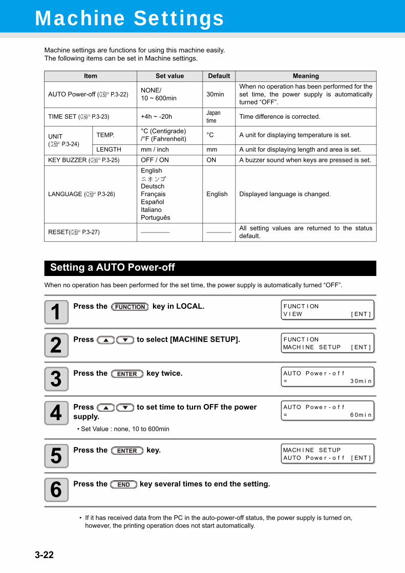
3-22
Machine SettingsMachine settings are functions for using this machine easily.The following items can be set in Machine settings.
Setting a AUTO Power-offWhen no operation has been performed for the set time, the power supply is automatically turned “OFF”.
1 Press the key in LOCAL.
2 Press to select [MACHINE SETUP].
3 Press the key twice.
4 Press to set time to turn OFF the power supply.
• Set Value : none, 10 to 600min
5 Press the key.
6 Press the key several times to end the setting.
Item Set value Default Meaning
AUTO Power-off ( P.3-22) NONE/10 ~ 600min 30min
When no operation has been performed for theset time, the power supply is automaticallyturned “OFF”.
TIME SET ( P.3-23) +4h ~ -20h Japantime Time difference is corrected.
UNIT ( P.3-24)
TEMP. °C (Centigrade)/°F (Fahrenheit) °C A unit for displaying temperature is set.
LENGTH mm / inch mm A unit for displaying length and area is set.KEY BUZZER ( P.3-25) OFF / ON ON A buzzer sound when keys are pressed is set.
LANGUAGE ( P.3-26)
English ニホンゴDeutschFrançaisEspañolItalianoPortuguês
English Displayed language is changed.
RESET( P.3-27) All setting values are returned to the statusdefault.
• If it has received data from the PC in the auto-power-off status, the power supply is turned on, however, the printing operation does not start automatically.
FUNCT I ONV I EW [ ENT ]
FUNCT I ONMACH I NE SETUP [ ENT ]
AUTO P owe r - o f f= 3 0m i n
AUTO P owe r - o f f= 6 0m i n
MACH I NE SETUPAUTO P owe r - o f f [ ENT ]
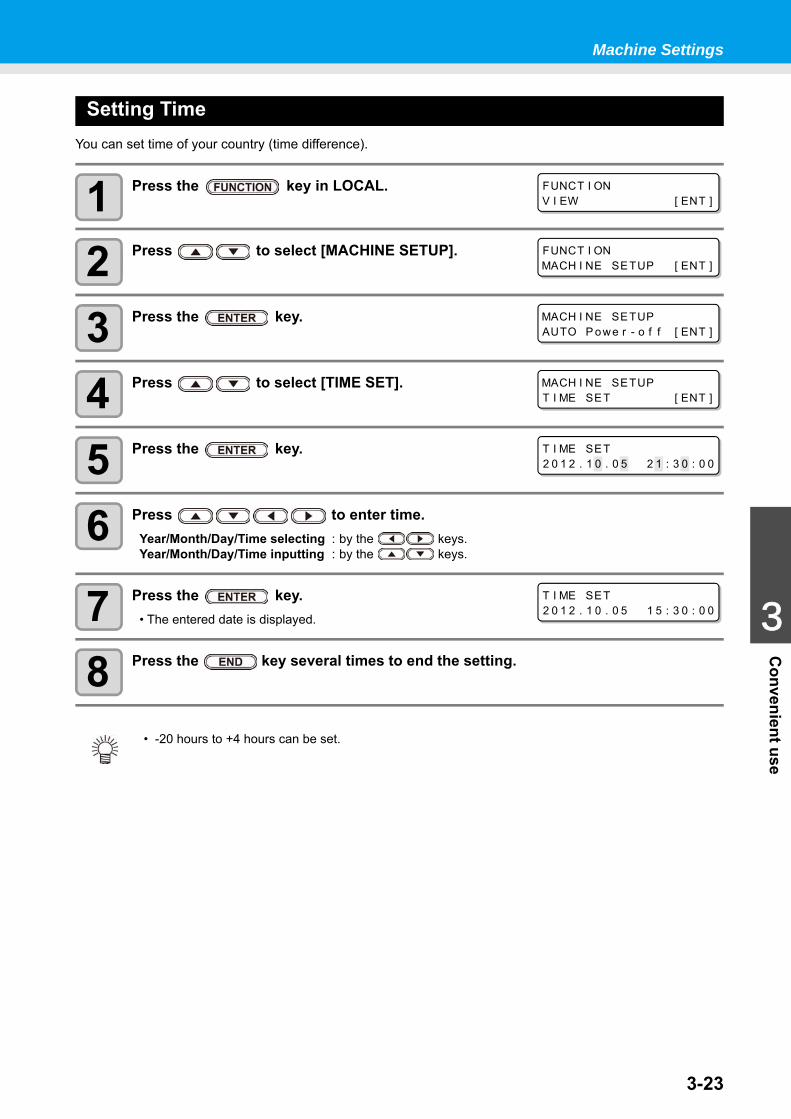
3-23
1
1
3
Convenient use
5
6
Machine Settings
Setting TimeYou can set time of your country (time difference).
1 Press the key in LOCAL.
2 Press to select [MACHINE SETUP].
3 Press the key.
4 Press to select [TIME SET].
5 Press the key.
6 Press to enter time.Year/Month/Day/Time selecting : by the keys.Year/Month/Day/Time inputting : by the keys.
7 Press the key.• The entered date is displayed.
8 Press the key several times to end the setting.
• -20 hours to +4 hours can be set.
FUNCT I ONV I EW [ ENT ]
FUNCT I ONMACH I NE SETUP [ ENT ]
MACH I NE SETUPAUTO P owe r - o f f [ ENT ]
MACH I NE SETUPT I ME SET [ ENT ]
T I ME SET2 0 1 2 . 1 0 . 0 5 2 1 : 3 0 : 0 0
T I ME SET2 0 1 2 . 1 0 . 0 5 1 5 : 3 0 : 0 0
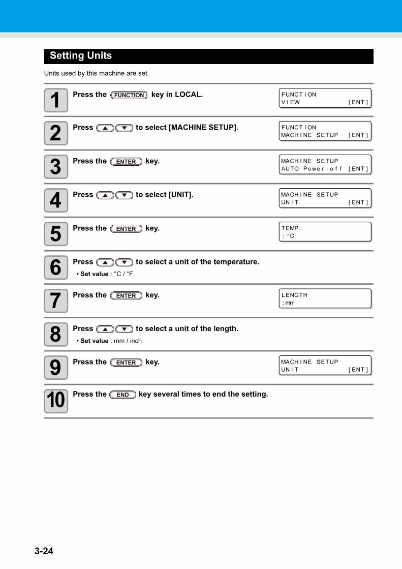
3-24
Setting UnitsUnits used by this machine are set.
1 Press the key in LOCAL.
2 Press to select [MACHINE SETUP].
3 Press the key.
4 Press to select [UNIT].
5 Press the key.
6 Press to select a unit of the temperature.• Set value : °C / °F
7 Press the key.
8 Press to select a unit of the length.• Set value : mm / inch
9 Press the key.
10 Press the key several times to end the setting.
FUNCT I ONV I EW [ ENT ]
FUNCT I ONMACH I NE SETUP [ ENT ]
MACH I NE SETUPAUTO P owe r - o f f [ ENT ]
MACH I NE SETUPUN I T [ ENT ]
TEMP .: ° C
L ENGTH: mm
MACH I NE SETUPUN I T [ ENT ]
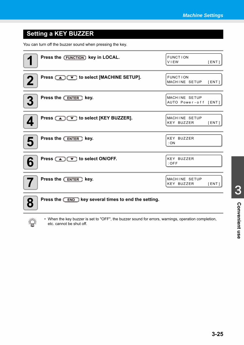
3-25
1
1
3
Convenient use
5
6
Machine Settings
Setting a KEY BUZZERYou can turn off the buzzer sound when pressing the key.
1 Press the key in LOCAL.
2 Press to select [MACHINE SETUP].
3 Press the key.
4 Press to select [KEY BUZZER].
5 Press the key.
6 Press to select ON/OFF.
7 Press the key.
8 Press the key several times to end the setting.
• When the key buzzer is set to "OFF", the buzzer sound for errors, warnings, operation completion, etc. cannot be shut off.
FUNCT I ONV I EW [ ENT ]
FUNCT I ONMACH I NE SETUP [ ENT ]
MACH I NE SETUPAUTO P owe r - o f f [ ENT ]
MACH I NE SETUPKEY BUZ ZER [ ENT ]
KEY BUZ ZER: ON
KEY BUZ ZER: OF F
MACH I NE SETUPKEY BUZ ZER [ ENT ]
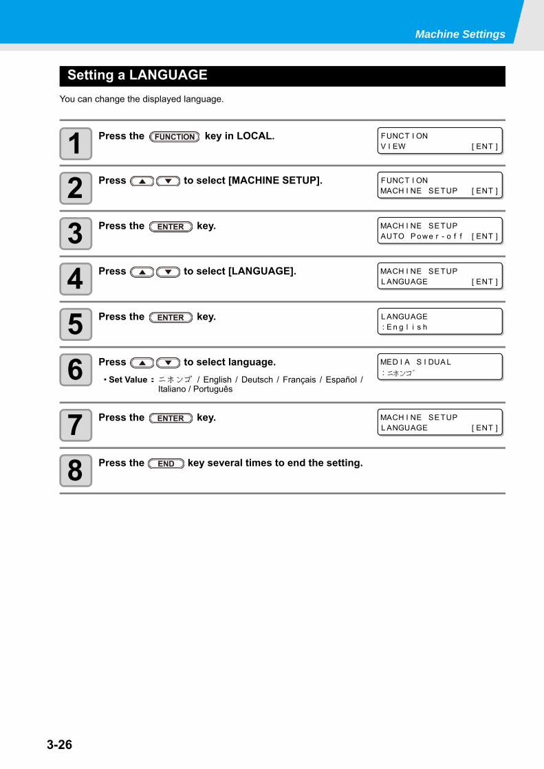
3-26
Machine Settings
Setting a LANGUAGEYou can change the displayed language.
1 Press the key in LOCAL.
2 Press to select [MACHINE SETUP].
3 Press the key.
4 Press to select [LANGUAGE].
5 Press the key.
6 Press to select language.• Set Value:ニホンゴ / English / Deutsch / Français / Español /
Italiano / Português
7 Press the key.
8 Press the key several times to end the setting.
FUNCT I ONV I EW [ ENT ]
FUNCT I ONMACH I NE SETUP [ ENT ]
MACH I NE SETUPAUTO P owe r - o f f [ ENT ]
MACH I NE SETUPL ANGUAGE [ ENT ]
L ANGUAGE: E n g l i s h
MED I A S I DUA L: ニホンコ゛
MACH I NE SETUPL ANGUAGE [ ENT ]
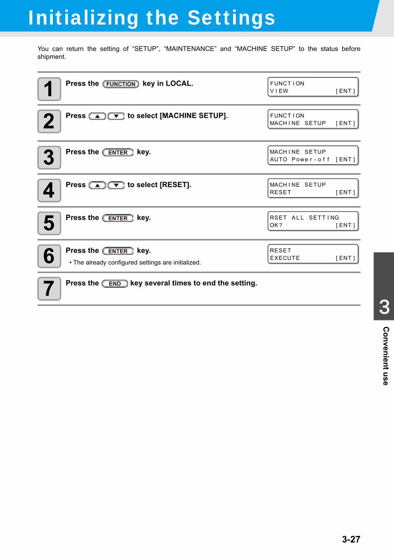
3-27
1
1
3
Convenient use
5
6
Initializing the SettingsYou can return the setting of “SETUP”, “MAINTENANCE” and “MACHINE SETUP” to the status beforeshipment.
1 Press the key in LOCAL.
2 Press to select [MACHINE SETUP].
3 Press the key.
4 Press to select [RESET].
5 Press the key.
6 Press the key.• The already configured settings are initialized.
7 Press the key several times to end the setting.
FUNCT I ONV I EW [ ENT ]
FUNCT I ONMACH I NE SETUP [ ENT ]
MACH I NE SETUPAUTO P owe r - o f f [ ENT ]
MACH I NE SETUPRESET [ ENT ]
RSET A L L SET T I NGOK ? [ ENT ]
RESETEXECUTE [ ENT ]
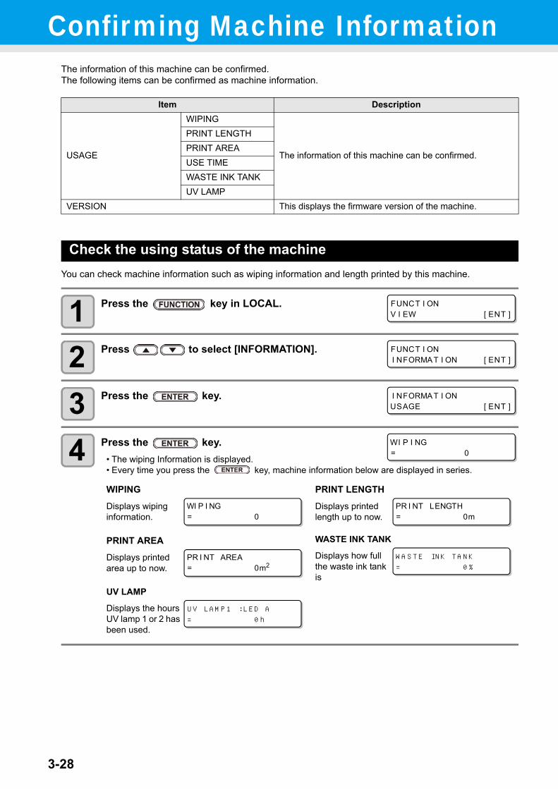
3-28
Confirming Machine InformationThe information of this machine can be confirmed.The following items can be confirmed as machine information.
Check the using status of the machineYou can check machine information such as wiping information and length printed by this machine.
1 Press the key in LOCAL.
2 Press to select [INFORMATION].
3 Press the key.
4 Press the key.• The wiping Information is displayed.• Every time you press the key, machine information below are displayed in series.
Item Description
USAGE
WIPING
The information of this machine can be confirmed.
PRINT LENGTHPRINT AREAUSE TIMEWASTE INK TANKUV LAMP
VERSION This displays the firmware version of the machine.
WIPINGDisplays wiping information.
PRINT LENGTHDisplays printed length up to now.
PRINT AREADisplays printed area up to now.
WASTE INK TANK
Displays how full the waste ink tank is
UV LAMP
Displays the hours UV lamp 1 or 2 has been used.
FUNCT I ONV I EW [ ENT ]
FUNCT I ONI NFORMAT I ON [ ENT ]
I NFORMAT I ONUSAGE [ ENT ]
WI P I NG= 0
WI P I NG= 0
PR I NT LENGTH= 0m
PR I NT AREA= 0m2
WASTE I NK TANK
= 0%
UV LAMP1 : L ED A
= 0 h
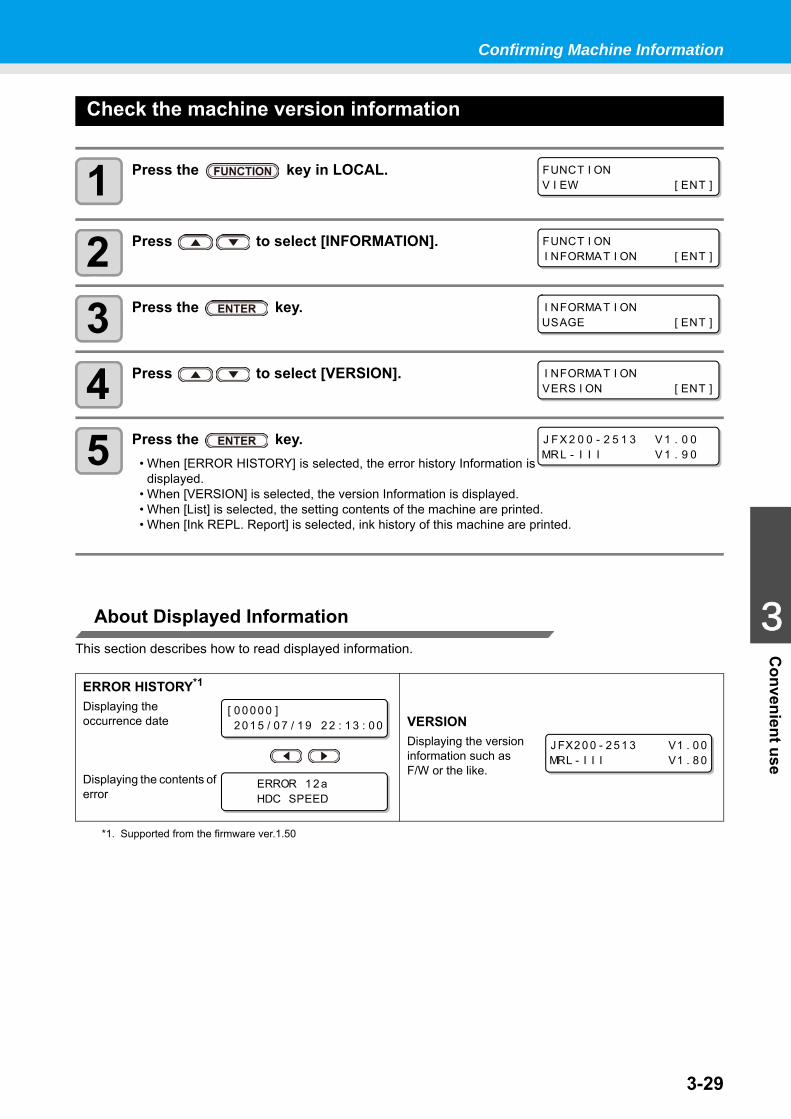
3-29
1
1
3
Convenient use
5
6
Confirming Machine Information
Check the machine version information
1 Press the key in LOCAL.
2 Press to select [INFORMATION].
3 Press the key.
4 Press to select [VERSION].
5 Press the key.• When [ERROR HISTORY] is selected, the error history Information is
displayed.• When [VERSION] is selected, the version Information is displayed.• When [List] is selected, the setting contents of the machine are printed.• When [Ink REPL. Report] is selected, ink history of this machine are printed.
About Displayed InformationThis section describes how to read displayed information.
ERROR HISTORY*1
Displaying the occurrence date
Displaying the contents of error
*1. Supported from the firmware ver.1.50
VERSIONDisplaying the version information such as F/W or the like.
FUNCT I ONV I EW [ ENT ]
FUNCT I ONI NFORMAT I ON [ ENT ]
I NFORMAT I ONUSAGE [ ENT ]
I NFORMAT I ONVERS I ON [ ENT ]
J FX 2 0 0 - 2 5 1 3 V 1 . 0 0MRL - I I I V 1 . 9 0
[ 0 0 0 0 0 ]2 0 1 5 / 0 7 / 1 9 2 2 : 1 3 : 0 0
ERROR 1 2 aHDC SPEED
J FX2 0 0 - 2 5 1 3 V1 . 0 0MRL - I I I V1 . 8 0
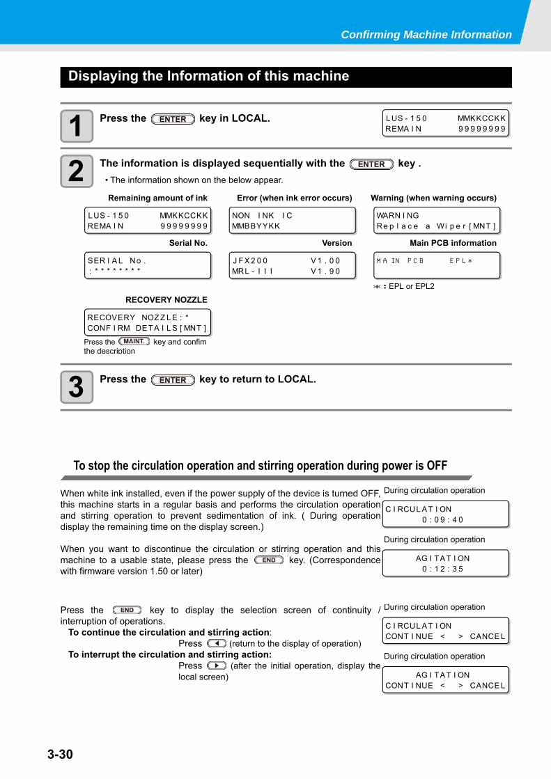
3-30
Confirming Machine Information
Displaying the Information of this machine
1 Press the key in LOCAL.
2 The information is displayed sequentially with the key .• The information shown on the below appear.
3 Press the key to return to LOCAL.
To stop the circulation operation and stirring operation during power is OFF
When white ink installed, even if the power supply of the device is turned OFF,this machine starts in a regular basis and performs the circulation operationand stirring operation to prevent sedimentation of ink. ( During operationdisplay the remaining time on the display screen.)
When you want to discontinue the circulation or stirring operation and thismachine to a usable state, please press the key. (Correspondencewith firmware version 1.50 or later)
Press the key to display the selection screen of continuity /interruption of operations.
To continue the circulation and stirring action:Press (return to the display of operation)
To interrupt the circulation and stirring action:Press (after the initial operation, display thelocal screen)
LUS - 1 5 0 MMKKCCKKREMA I N 9 9 9 9 9 9 9 9
Remaining amount of ink Error (when ink error occurs) Warning (when warning occurs)
Serial No. Version Main PCB information
RECOVERY NOZZLE
LUS - 1 5 0 MMKKCCKKREMA I N 9 9 9 9 9 9 9 9
NON I NK I CMMBBYYKK
WARN I NGRe p l a c e a Wi p e r [ MNT ]
SER I A L No .: * * * * * * * *
J FX 2 0 0 V 1 . 0 0MRL - I I I V 1 . 9 0
MA I N P CB E P L *
*:EPL or EPL2
RECOVERY NOZ Z L E : *CONF I RM DETA I L S [ MNT ]
Press the key and confim the description
C I RCUL AT I ON0 : 0 9 : 4 0
During circulation operation
AG I TAT I ON0 : 1 2 : 3 5
During circulation operation
C I RCUL AT I ONCONT I NUE < > CANCE L
During circulation operation
AG I TAT I ONCONT I NUE < > CANCE L
During circulation operation
This chapter
describes the items required to use this machine more comfortably, which are themethods for the daily care, the maintenance of the ink unit etc.
Maintenance .................................................4-2Precautions for Maintenance ...................... 4-2About Cleaning liquid .................................. 4-2Maintenance of frame component ............... 4-2MBIS Maintenance ...................................... 4-3Cleaning the LM guide ................................ 4-3
Maintaining the Capping Station ...................4-4Cleaning the Wiper and Cap ....................... 4-4Cleaning the around station ........................ 4-7
Cleaning the Head and the Area around It ...4-8Washing the Ink Discharge Passage (DISWAY WASH) ...................................... 4-10When the Machine Is Not Used for a Long Time (CUSTODY WASH) ......................... 4-11
When Nozzle Clogging Cannot Be Solved .4-14Filling with ink from the sub tank to the head .......................................................... 4-14Washing of Head nozzle ........................... 4-15If nozzle missing due to color mixture of ink or aeration ................................................. 4-17Alternative nozzles for printing, when nozzles missing can not be improved ............................. 4-20
Automatic Maintenance Function ................4-25Setting the Refreshing Intervals .................4-25Setting the Cleaning Intervals ....................4-26
Replacing consumables ..............................4-27Replacing the wiper ...................................4-27If a Waste Ink Tank Confirmation Message Appears .....................................................4-28Replacing the waste ink tank before the waste ink tank confirmation message is displayed (1) ...........................................4-31Replacing the waste ink tank before the waste ink tank confirmation message is displayed (2) ...........................................4-32
Refilling antifreeze mixed water ..................4-33Refill cooling water .....................................4-34
Exchange the flushing filter .........................4-36If a Flushing Filter Exchange Message Appears .....................................................4-36Replacing the flushing filter before the replacement message is displayed ............4-37
Chapter 4Maintenance
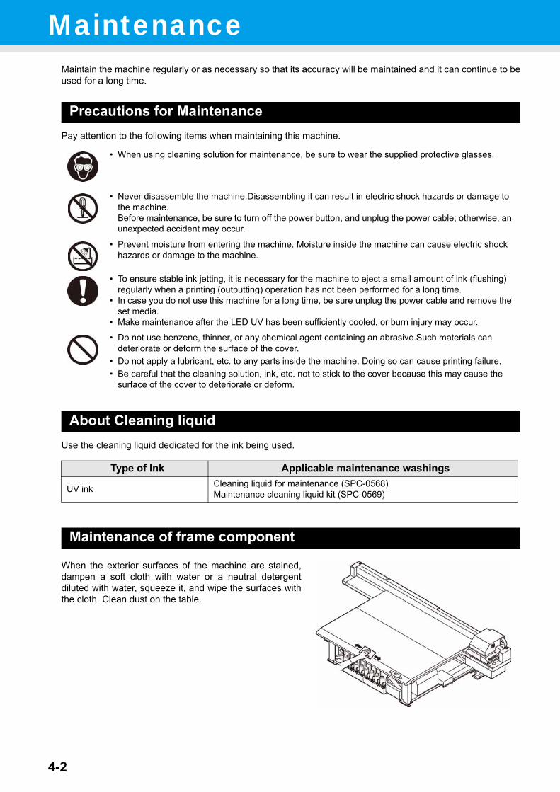
4-2
MaintenanceMaintain the machine regularly or as necessary so that its accuracy will be maintained and it can continue to beused for a long time.
Precautions for MaintenancePay attention to the following items when maintaining this machine.
About Cleaning liquidUse the cleaning liquid dedicated for the ink being used.
Maintenance of frame component
When the exterior surfaces of the machine are stained,dampen a soft cloth with water or a neutral detergentdiluted with water, squeeze it, and wipe the surfaces withthe cloth. Clean dust on the table.
• When using cleaning solution for maintenance, be sure to wear the supplied protective glasses.
• Never disassemble the machine.Disassembling it can result in electric shock hazards or damage to the machine.Before maintenance, be sure to turn off the power button, and unplug the power cable; otherwise, an unexpected accident may occur.
• Prevent moisture from entering the machine. Moisture inside the machine can cause electric shock hazards or damage to the machine.
• To ensure stable ink jetting, it is necessary for the machine to eject a small amount of ink (flushing) regularly when a printing (outputting) operation has not been performed for a long time.
• In case you do not use this machine for a long time, be sure unplug the power cable and remove the set media.
• Make maintenance after the LED UV has been sufficiently cooled, or burn injury may occur.
• Do not use benzene, thinner, or any chemical agent containing an abrasive.Such materials can deteriorate or deform the surface of the cover.
• Do not apply a lubricant, etc. to any parts inside the machine. Doing so can cause printing failure.• Be careful that the cleaning solution, ink, etc. not to stick to the cover because this may cause the
surface of the cover to deteriorate or deform.
Type of Ink Applicable maintenance washings
UV ink Cleaning liquid for maintenance (SPC-0568)Maintenance cleaning liquid kit (SPC-0569)
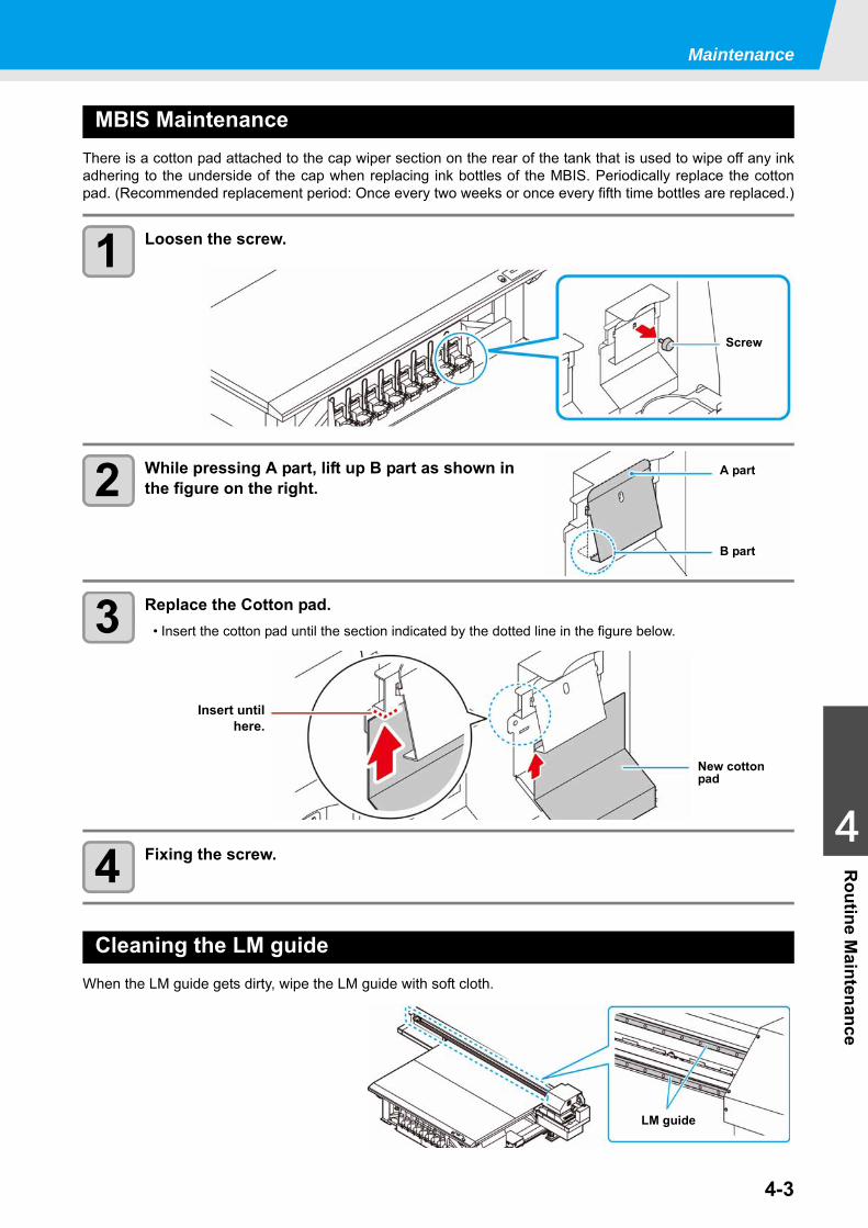
Maintenance
4-3
1
1
1
4
Routine M
aintenance
MBIS MaintenanceThere is a cotton pad attached to the cap wiper section on the rear of the tank that is used to wipe off any inkadhering to the underside of the cap when replacing ink bottles of the MBIS. Periodically replace the cottonpad. (Recommended replacement period: Once every two weeks or once every fifth time bottles are replaced.)
1 Loosen the screw.
2 While pressing A part, lift up B part as shown in the figure on the right.
3 Replace the Cotton pad.• Insert the cotton pad until the section indicated by the dotted line in the figure below.
4 Fixing the screw.
Cleaning the LM guideWhen the LM guide gets dirty, wipe the LM guide with soft cloth.
Screw
A part
B part
New cotton pad
Insert untilhere.
LM guide
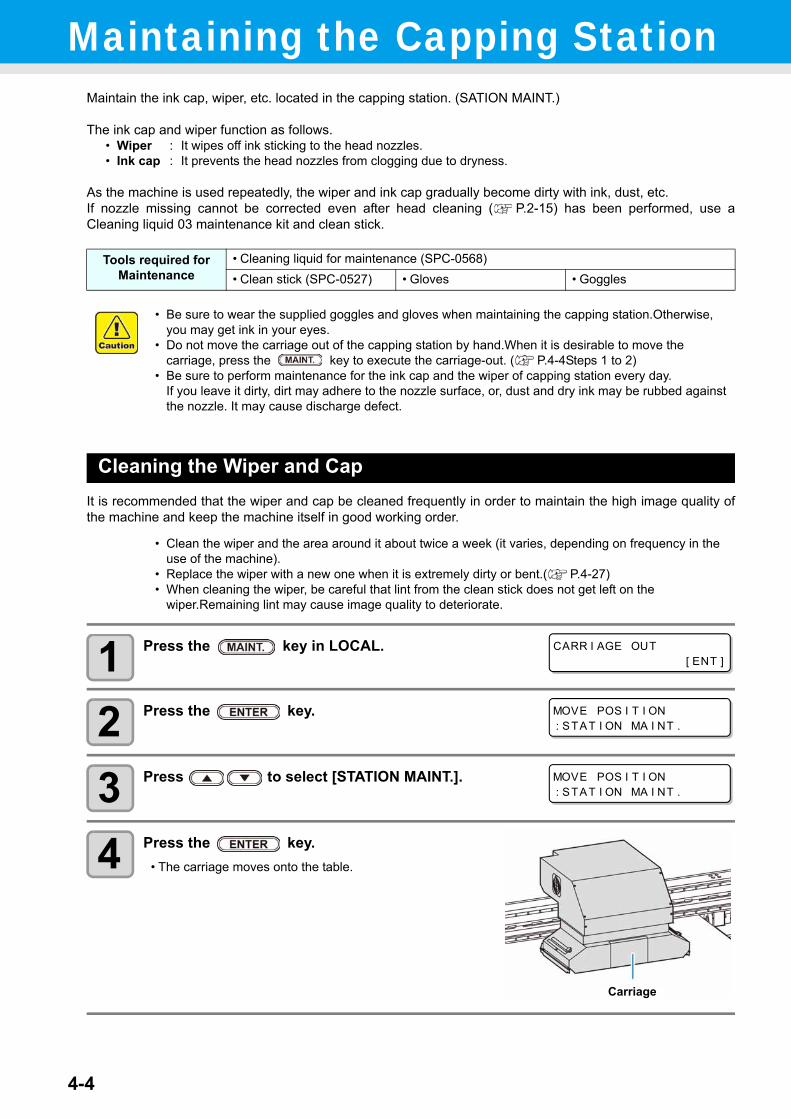
4-4
Maintaining the Capping StationMaintain the ink cap, wiper, etc. located in the capping station. (SATION MAINT.)
The ink cap and wiper function as follows.• Wiper : It wipes off ink sticking to the head nozzles.• Ink cap : It prevents the head nozzles from clogging due to dryness.
As the machine is used repeatedly, the wiper and ink cap gradually become dirty with ink, dust, etc.If nozzle missing cannot be corrected even after head cleaning ( P.2-15) has been performed, use aCleaning liquid 03 maintenance kit and clean stick.
Cleaning the Wiper and CapIt is recommended that the wiper and cap be cleaned frequently in order to maintain the high image quality ofthe machine and keep the machine itself in good working order.
1 Press the key in LOCAL.
2 Press the key.
3 Press to select [STATION MAINT.].
4 Press the key.• The carriage moves onto the table.
Tools required for Maintenance
• Cleaning liquid for maintenance (SPC-0568)• Clean stick (SPC-0527) • Gloves • Goggles
• Be sure to wear the supplied goggles and gloves when maintaining the capping station.Otherwise, you may get ink in your eyes.
• Do not move the carriage out of the capping station by hand.When it is desirable to move the carriage, press the key to execute the carriage-out. ( P.4-4Steps 1 to 2)
• Be sure to perform maintenance for the ink cap and the wiper of capping station every day. If you leave it dirty, dirt may adhere to the nozzle surface, or, dust and dry ink may be rubbed against the nozzle. It may cause discharge defect.
• Clean the wiper and the area around it about twice a week (it varies, depending on frequency in the use of the machine).
• Replace the wiper with a new one when it is extremely dirty or bent.( P.4-27)• When cleaning the wiper, be careful that lint from the clean stick does not get left on the
wiper.Remaining lint may cause image quality to deteriorate.
CARR I AGE OUT[ ENT ]
MOVE POS I T I ON: STAT I ON MA I NT .
MOVE POS I T I ON: STAT I ON MA I NT .
Carriage
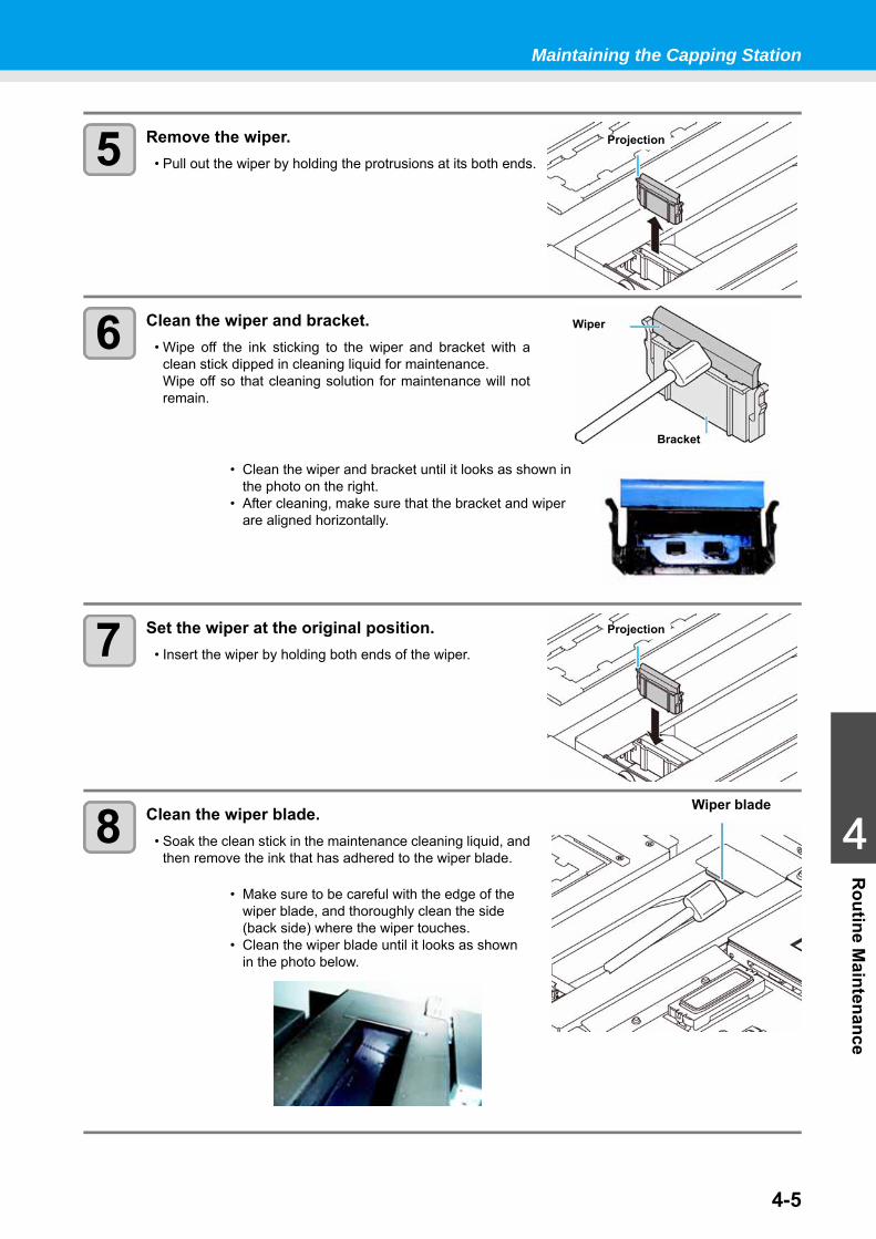
Maintaining the Capping Station
4-5
1
1
1
4
Routine M
aintenance
5 Remove the wiper.• Pull out the wiper by holding the protrusions at its both ends.
6 Clean the wiper and bracket.• Wipe off the ink sticking to the wiper and bracket with a
clean stick dipped in cleaning liquid for maintenance.Wipe off so that cleaning solution for maintenance will notremain.
7 Set the wiper at the original position.• Insert the wiper by holding both ends of the wiper.
8 Clean the wiper blade.• Soak the clean stick in the maintenance cleaning liquid, and
then remove the ink that has adhered to the wiper blade.
• Clean the wiper and bracket until it looks as shown in the photo on the right.
• After cleaning, make sure that the bracket and wiper are aligned horizontally.
• Make sure to be careful with the edge of the wiper blade, and thoroughly clean the side (back side) where the wiper touches.
• Clean the wiper blade until it looks as shown in the photo below.
Projection
Wiper
Bracket
Projection
Wiper blade
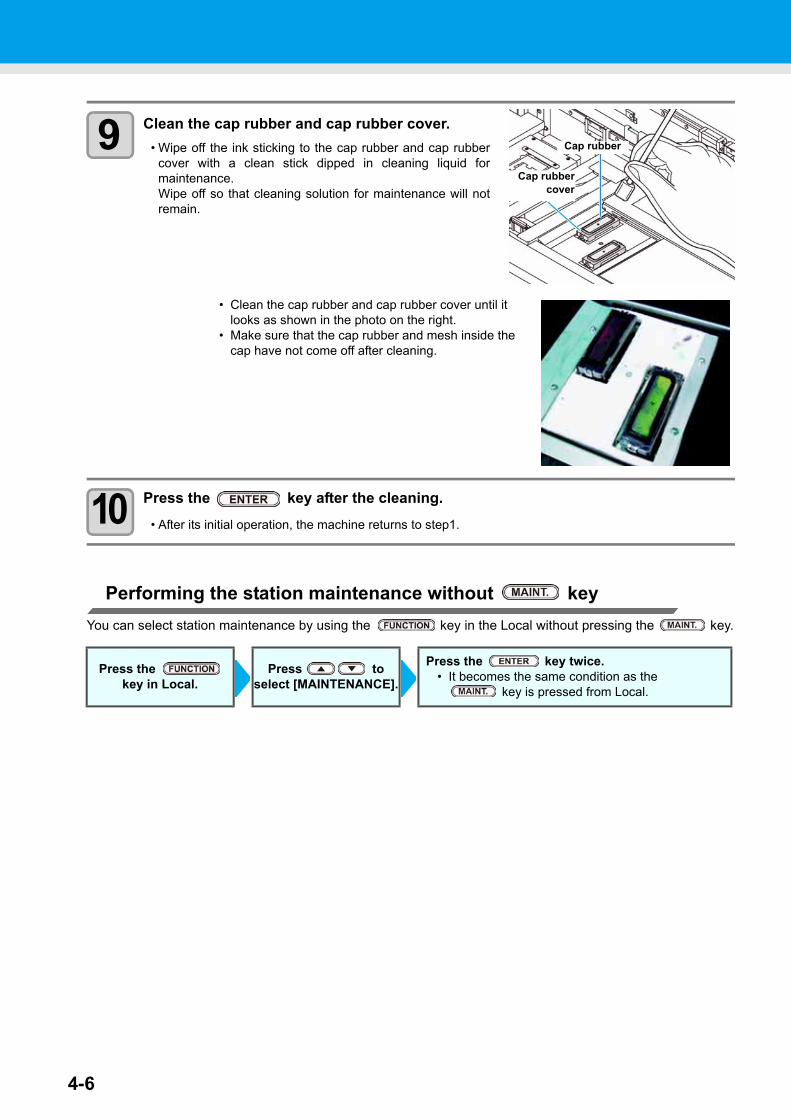
4-6
9 Clean the cap rubber and cap rubber cover.• Wipe off the ink sticking to the cap rubber and cap rubber
cover with a clean stick dipped in cleaning liquid formaintenance.Wipe off so that cleaning solution for maintenance will notremain.
10 Press the key after the cleaning.• After its initial operation, the machine returns to step1.
Performing the station maintenance without keyYou can select station maintenance by using the key in the Local without pressing the key.
• Clean the cap rubber and cap rubber cover until it looks as shown in the photo on the right.
• Make sure that the cap rubber and mesh inside the cap have not come off after cleaning.
Press the key in Local.
Press to select [MAINTENANCE].
Press the key twice.• It becomes the same condition as the
key is pressed from Local.
Cap rubber
Cap rubbercover
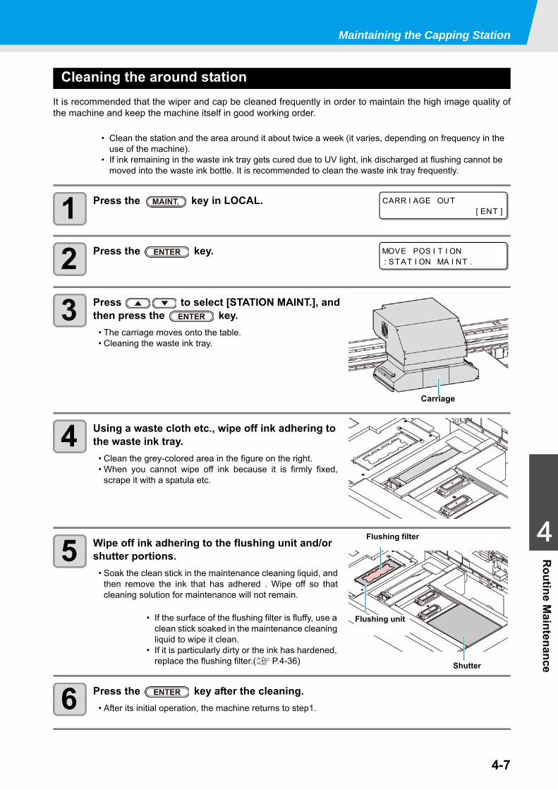
Maintaining the Capping Station
4-7
1
1
1
4
Routine M
aintenance
Cleaning the around stationIt is recommended that the wiper and cap be cleaned frequently in order to maintain the high image quality ofthe machine and keep the machine itself in good working order.
1 Press the key in LOCAL.
2 Press the key.
3 Press to select [STATION MAINT.], and then press the key.
• The carriage moves onto the table.• Cleaning the waste ink tray.
4 Using a waste cloth etc., wipe off ink adhering to the waste ink tray.
• Clean the grey-colored area in the figure on the right.• When you cannot wipe off ink because it is firmly fixed,
scrape it with a spatula etc.
5 Wipe off ink adhering to the flushing unit and/or shutter portions.
• Soak the clean stick in the maintenance cleaning liquid, andthen remove the ink that has adhered . Wipe off so thatcleaning solution for maintenance will not remain.
6 Press the key after the cleaning.• After its initial operation, the machine returns to step1.
• Clean the station and the area around it about twice a week (it varies, depending on frequency in the use of the machine).
• If ink remaining in the waste ink tray gets cured due to UV light, ink discharged at flushing cannot be moved into the waste ink bottle. It is recommended to clean the waste ink tray frequently.
• If the surface of the flushing filter is fluffy, use a clean stick soaked in the maintenance cleaning liquid to wipe it clean.
• If it is particularly dirty or the ink has hardened, replace the flushing filter.( P.4-36)
CARR I AGE OUT[ ENT ]
MOVE POS I T I ON: STAT I ON MA I NT .
Carriage
Flushing unit
Shutter
Flushing filter
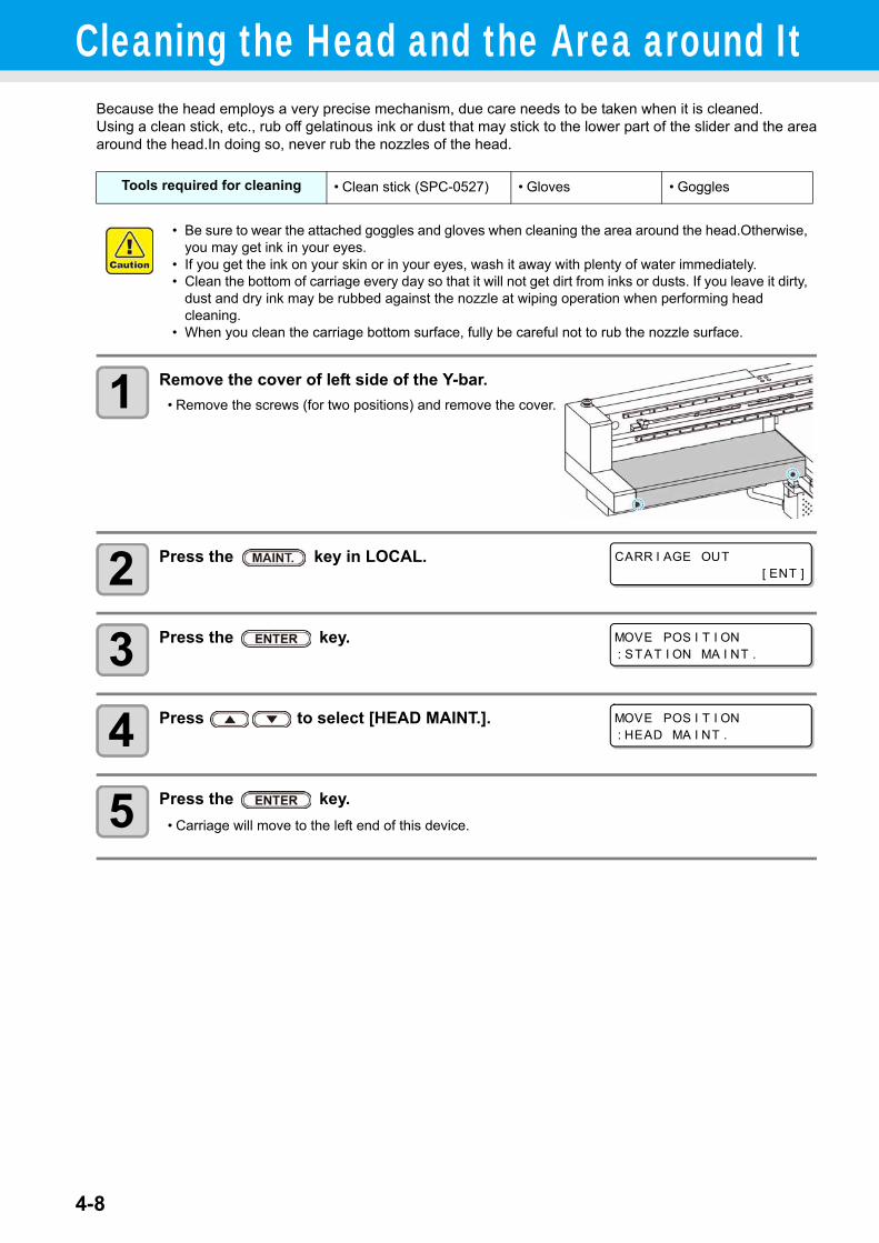
4-8
Cleaning the Head and the Area around ItBecause the head employs a very precise mechanism, due care needs to be taken when it is cleaned.Using a clean stick, etc., rub off gelatinous ink or dust that may stick to the lower part of the slider and the areaaround the head.In doing so, never rub the nozzles of the head.
1 Remove the cover of left side of the Y-bar.• Remove the screws (for two positions) and remove the cover.
2 Press the key in LOCAL.
3 Press the key.
4 Press to select [HEAD MAINT.].
5 Press the key.• Carriage will move to the left end of this device.
Tools required for cleaning • Clean stick (SPC-0527) • Gloves • Goggles
• Be sure to wear the attached goggles and gloves when cleaning the area around the head.Otherwise, you may get ink in your eyes.
• If you get the ink on your skin or in your eyes, wash it away with plenty of water immediately.• Clean the bottom of carriage every day so that it will not get dirt from inks or dusts. If you leave it dirty,
dust and dry ink may be rubbed against the nozzle at wiping operation when performing head cleaning.
• When you clean the carriage bottom surface, fully be careful not to rub the nozzle surface.
CARR I AGE OUT[ ENT ]
MOVE POS I T I ON: STAT I ON MA I NT .
MOVE POS I T I ON: HEAD MA I NT .
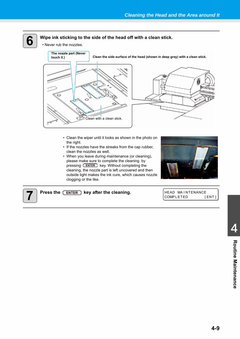
Cleaning the Head and the Area around It
4-9
1
1
1
4
Routine M
aintenance
6 Wipe ink sticking to the side of the head off with a clean stick.• Never rub the nozzles.
7 Press the key after the cleaning.
• Clean the wiper until it looks as shown in the photo on the right.
• If the nozzles have the streaks from the cap rubber, clean the nozzles as well.
• When you leave during maintenance (or cleaning), please make sure to complete the cleaning by pressing key. Without completing the cleaning, the nozzle part is left uncovered and then outside light makes the ink cure, which causes nozzle clogging or the like.
The nozzle part (Never touch it.) Clean the side surface of the head (shown in deep gray) with a clean stick.
Clean with a clean stick.
HEAD MA I NTENANCECOMP L ETED [ ENT ]
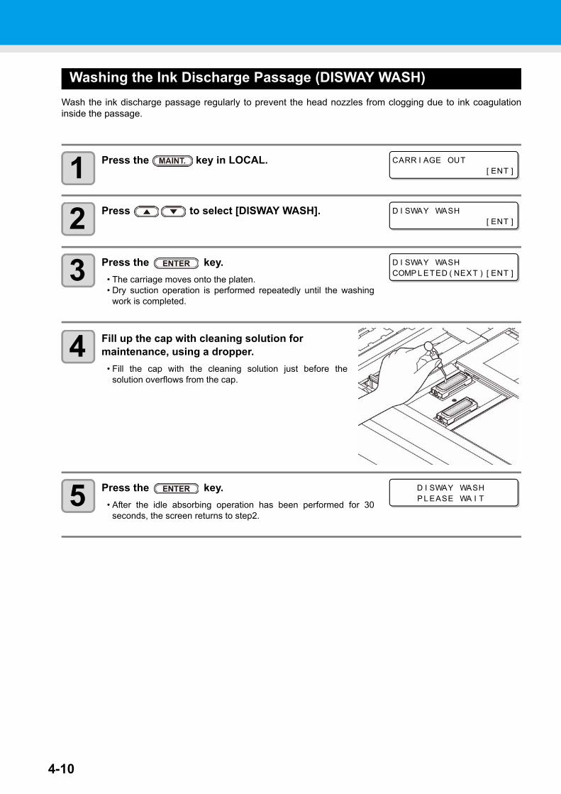
4-10
Washing the Ink Discharge Passage (DISWAY WASH)Wash the ink discharge passage regularly to prevent the head nozzles from clogging due to ink coagulationinside the passage.
1 Press the key in LOCAL.
2 Press to select [DISWAY WASH].
3 Press the key.• The carriage moves onto the platen.• Dry suction operation is performed repeatedly until the washing
work is completed.
4 Fill up the cap with cleaning solution for maintenance, using a dropper.
• Fill the cap with the cleaning solution just before thesolution overflows from the cap.
5 Press the key.• After the idle absorbing operation has been performed for 30
seconds, the screen returns to step2.
CARR I AGE OUT[ ENT ]
D I SWAY WASH[ ENT ]
D I SWAY WASHCOMP L ETED ( NEXT ) [ ENT ]
D I SWAY WASHP L EASE WA I T
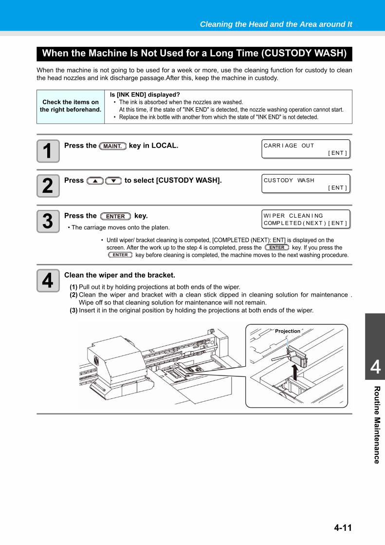
Cleaning the Head and the Area around It
4-11
1
1
1
4
Routine M
aintenance
When the Machine Is Not Used for a Long Time (CUSTODY WASH)When the machine is not going to be used for a week or more, use the cleaning function for custody to cleanthe head nozzles and ink discharge passage.After this, keep the machine in custody.
1 Press the key in LOCAL.
2 Press to select [CUSTODY WASH].
3 Press the key.• The carriage moves onto the platen.
4 Clean the wiper and the bracket.(1) Pull out it by holding projections at both ends of the wiper.(2) Clean the wiper and bracket with a clean stick dipped in cleaning solution for maintenance .
Wipe off so that cleaning solution for maintenance will not remain.(3) Insert it in the original position by holding the projections at both ends of the wiper.
Check the items on the right beforehand.
Is [INK END] displayed?• The ink is absorbed when the nozzles are washed.
At this time, if the state of "INK END" is detected, the nozzle washing operation cannot start.• Replace the ink bottle with another from which the state of "INK END" is not detected.
• Until wiper/ bracket cleaning is competed, [COMPLETED (NEXT): ENT] is displayed on the screen. After the work up to the step 4 is completed, press the key. If you press the
key before cleaning is completed, the machine moves to the next washing procedure.
CARR I AGE OUT[ ENT ]
CUSTODY WASH[ ENT ]
WI PER CL EAN I NGCOMP L ETED ( NEXT ) [ ENT ]
Projection
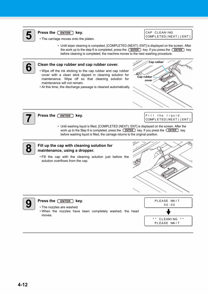
4-12
5 Press the key.• The carriage moves onto the platen.
6 Clean the cap rubber and cap rubber cover.• Wipe off the ink sticking to the cap rubber and cap rubber
cover with a clean stick dipped in cleaning solution formaintenance. Wipe off so that cleaning solution formaintenance will not remain.
• At this time, the discharge passage is cleaned automatically.
7 Press the key.
8 Fill up the cap with cleaning solution for maintenance, using a dropper.
• Fill the cap with the cleaning solution just before thesolution overflows from the cap.
9 Press the key.• The nozzles are washed.• When the nozzles have been completely washed, the head
moves.
• Until wiper cleaning is competed, [COMPLETED (NEXT): ENT] is displayed on the screen. After the work up to the step 6 is completed, press the key. If you press the key before cleaning is completed, the machine moves to the next washing procedure.
• Until washing liquid is filled, [COMPLETED (NEXT): ENT] is displayed on the screen. After the work up to the Step 8 is completed, press the key. If you press the key before washing liquid is filled, the carriage returns to the original position.
CAP CL EAN I NGCOMP L ETED ( NEXT ) [ ENT ]
Cap rubber
Cap rubbercover
F i l l t h e l i q u i d .COMP L ETED ( NEXT ) [ ENT ]
P L EASE WA I T0 0 : 0 0
* * CL EAM I NG * *P L EASE WA I T
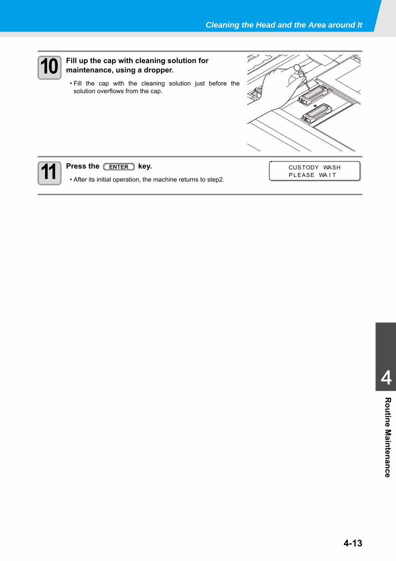
Cleaning the Head and the Area around It
4-13
1
1
1
4
Routine M
aintenance
10 Fill up the cap with cleaning solution for maintenance, using a dropper.
• Fill the cap with the cleaning solution just before thesolution overflows from the cap.
11 Press the key.• After its initial operation, the machine returns to step2.
CUSTODY WASHP L EASE WA I T
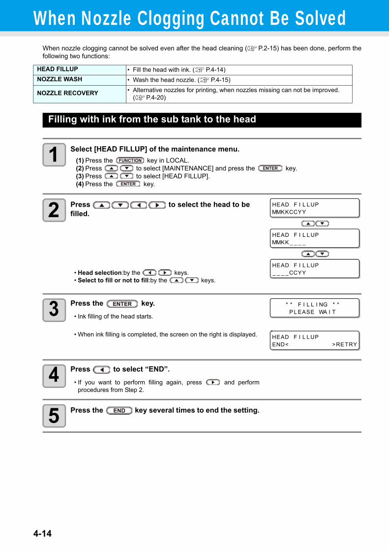
4-14
When Nozzle Clogging Cannot Be SolvedWhen nozzle clogging cannot be solved even after the head cleaning ( P.2-15) has been done, perform thefollowing two functions:
Filling with ink from the sub tank to the head
1 Select [HEAD FILLUP] of the maintenance menu.(1) Press the key in LOCAL.(2) Press to select [MAINTENANCE] and press the key.(3) Press to select [HEAD FILLUP].(4) Press the key.
2 Press to select the head to be filled.
• Head selection:by the keys.• Select to fill or not to fill:by the keys.
3 Press the key.• Ink filling of the head starts.
• When ink filling is completed, the screen on the right is displayed.
4 Press to select “END”.• If you want to perform filling again, press and perform
procedures from Step 2.
5 Press the key several times to end the setting.
HEAD FILLUP • Fill the head with ink. ( P.4-14)NOZZLE WASH • Wash the head nozzle. ( P.4-15)
NOZZLE RECOVERY • Alternative nozzles for printing, when nozzles missing can not be improved. ( P.4-20)
HEAD F I L LUPMMKKCCYY
HEAD F I L LUP_ _ _ _CCYY
HEAD F I L LUPMMKK _ _ _ _
* * F I L L I NG * *P L EASE WA I T
HEAD F I L LUPEND< >RETRY
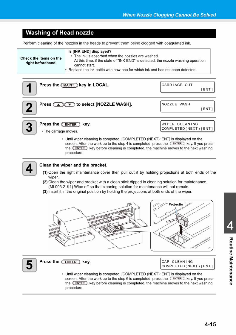
When Nozzle Clogging Cannot Be Solved
4-15
1
1
1
4
Routine M
aintenance
Washing of Head nozzlePerform cleaning of the nozzles in the heads to prevent them being clogged with coagulated ink.
1 Press the key in LOCAL.
2 Press to select [NOZZLE WASH].
3 Press the key.• The carriage moves.
4 Clean the wiper and the bracket.(1) Open the right maintenance cover then pull out it by holding projections at both ends of the
wiper.(2) Clean the wiper and bracket with a clean stick dipped in cleaning solution for maintenance.
(ML003-Z-K1) Wipe off so that cleaning solution for maintenance will not remain.(3) Insert it in the original position by holding the projections at both ends of the wiper.
5 Press the key.
Check the items on the right beforehand.
Is [INK END] displayed?• The ink is absorbed when the nozzles are washed.
At this time, if the state of "INK END" is detected, the nozzle washing operation cannot start.
• Replace the ink bottle with new one for which ink end has not been detected.
• Until wiper cleaning is competed, [COMPLETED (NEXT): ENT] is displayed on the screen. After the work up to the step 4 is completed, press the key. If you press the key before cleaning is completed, the machine moves to the next washing procedure.
• Until wiper cleaning is competed, [COMPLETED (NEXT): ENT] is displayed on the screen. After the work up to the step 6 is completed, press the key. If you press the key before cleaning is completed, the machine moves to the next washing procedure.
CARR I AGE OUT[ ENT ]
NOZ Z L E WASH[ ENT ]
WI PER CL EAN I NGCOMP L ETED ( NEXT ) [ ENT ]
Projectio
CAP CL EAN I NGCOMP L ETED ( NEXT ) [ ENT ]
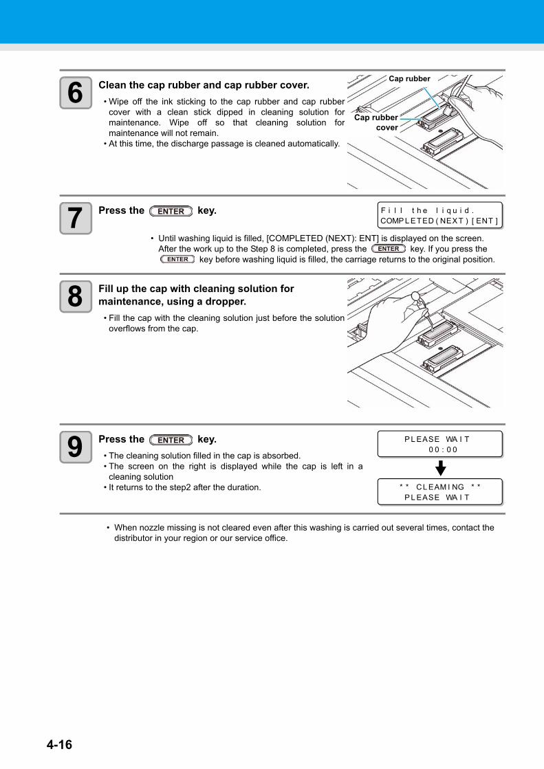
4-16
6 Clean the cap rubber and cap rubber cover.• Wipe off the ink sticking to the cap rubber and cap rubber
cover with a clean stick dipped in cleaning solution formaintenance. Wipe off so that cleaning solution formaintenance will not remain.
• At this time, the discharge passage is cleaned automatically.
7 Press the key.
8 Fill up the cap with cleaning solution for maintenance, using a dropper.
• Fill the cap with the cleaning solution just before the solutionoverflows from the cap.
9 Press the key.• The cleaning solution filled in the cap is absorbed.• The screen on the right is displayed while the cap is left in a
cleaning solution• It returns to the step2 after the duration.
• Until washing liquid is filled, [COMPLETED (NEXT): ENT] is displayed on the screen. After the work up to the Step 8 is completed, press the key. If you press the
key before washing liquid is filled, the carriage returns to the original position.
• When nozzle missing is not cleared even after this washing is carried out several times, contact the distributor in your region or our service office.
Cap rubber
Cap rubbercover
F i l l t h e l i q u i d .COMP L ETED ( NEXT ) [ ENT ]
P L EASE WA I T0 0 : 0 0
* * CL EAM I NG * *P L EASE WA I T
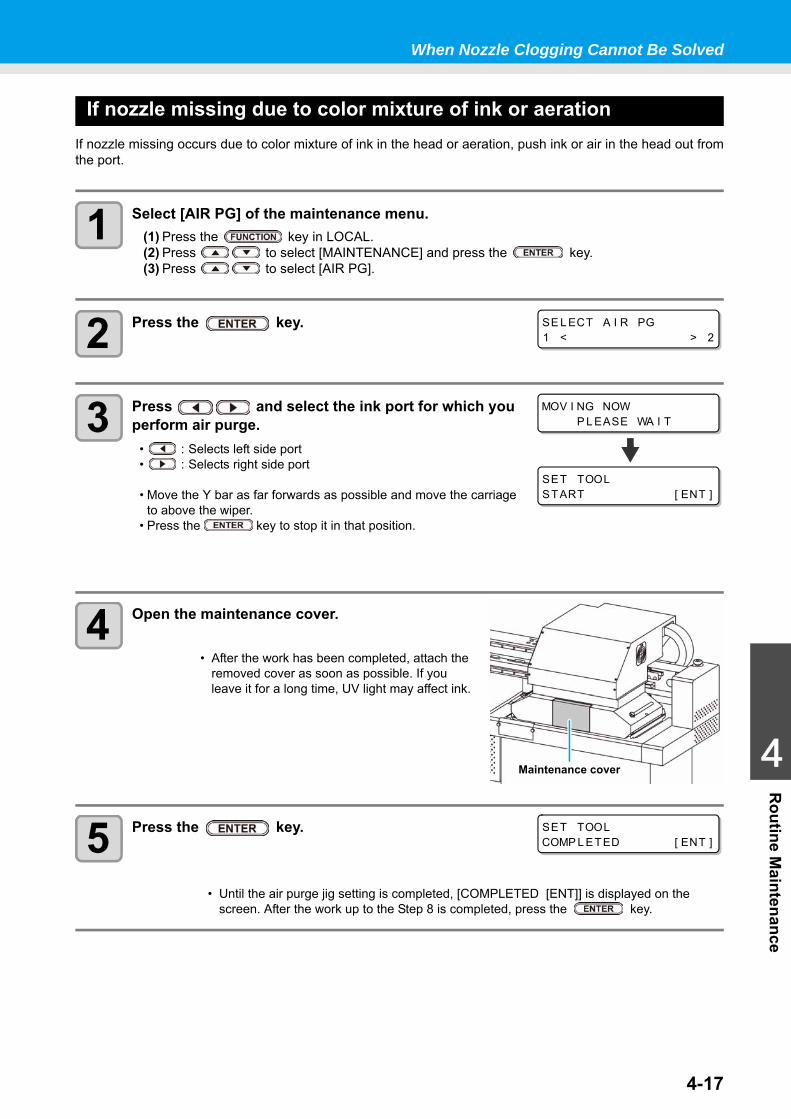
When Nozzle Clogging Cannot Be Solved
4-17
1
1
1
4
Routine M
aintenance
If nozzle missing due to color mixture of ink or aerationIf nozzle missing occurs due to color mixture of ink in the head or aeration, push ink or air in the head out fromthe port.
1 Select [AIR PG] of the maintenance menu.(1) Press the key in LOCAL.(2) Press to select [MAINTENANCE] and press the key.(3) Press to select [AIR PG].
2 Press the key.
3 Press and select the ink port for which you perform air purge.
• : Selects left side port• : Selects right side port
• Move the Y bar as far forwards as possible and move the carriageto above the wiper.
• Press the key to stop it in that position.
4 Open the maintenance cover.
5 Press the key.
• After the work has been completed, attach the removed cover as soon as possible. If you leave it for a long time, UV light may affect ink.
• Until the air purge jig setting is completed, [COMPLETED [ENT]] is displayed on the screen. After the work up to the Step 8 is completed, press the key.
SE L ECT A I R PG1 < > 2
MOV I NG NOWP L EASE WA I T
SET TOOLSTART [ ENT ]
Maintenance cover
SET TOOLCOMP L ETED [ ENT ]
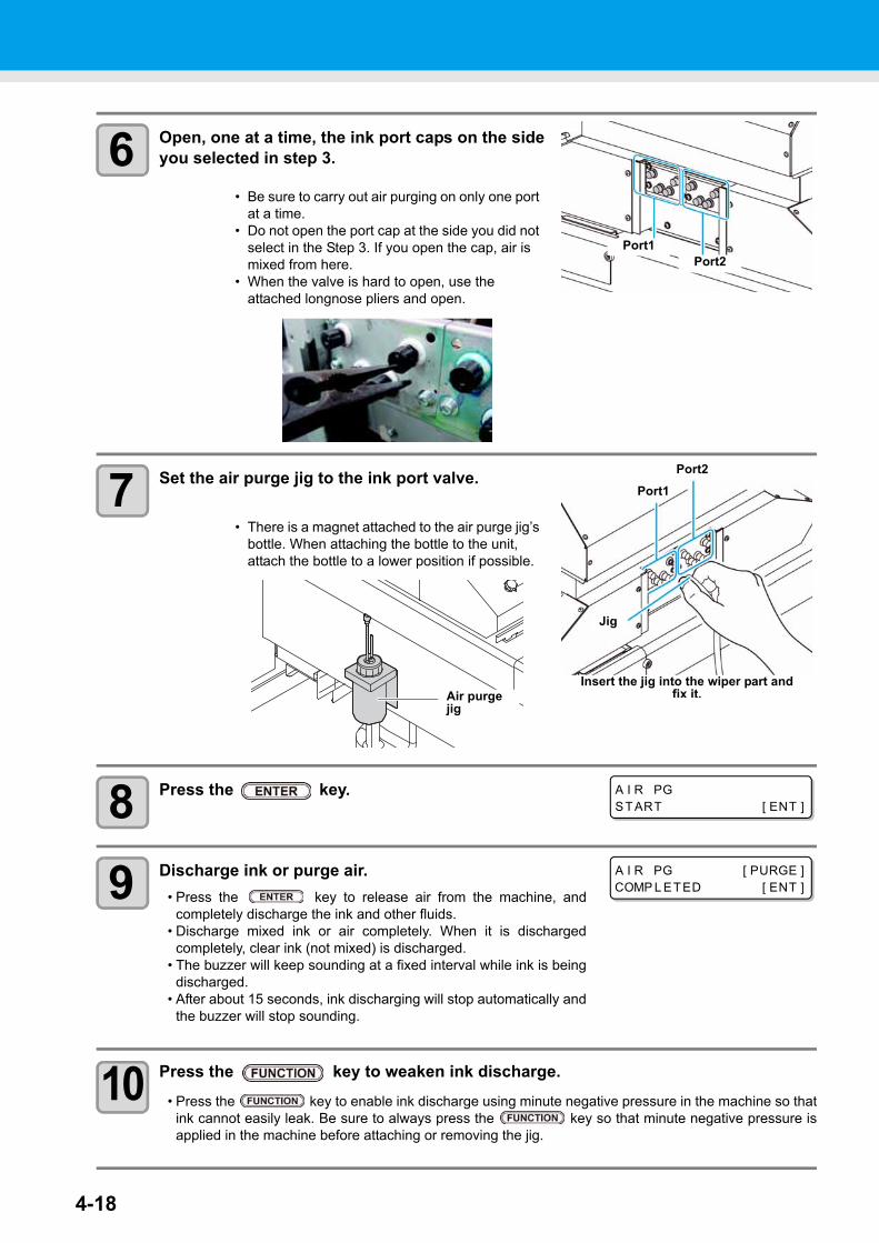
4-18
6 Open, one at a time, the ink port caps on the side you selected in step 3.
7 Set the air purge jig to the ink port valve.
8 Press the key.
9 Discharge ink or purge air.• Press the key to release air from the machine, and
completely discharge the ink and other fluids.• Discharge mixed ink or air completely. When it is discharged
completely, clear ink (not mixed) is discharged.• The buzzer will keep sounding at a fixed interval while ink is being
discharged.• After about 15 seconds, ink discharging will stop automatically and
the buzzer will stop sounding.
10 Press the key to weaken ink discharge. • Press the key to enable ink discharge using minute negative pressure in the machine so that
ink cannot easily leak. Be sure to always press the key so that minute negative pressure isapplied in the machine before attaching or removing the jig.
• Be sure to carry out air purging on only one port at a time.
• Do not open the port cap at the side you did not select in the Step 3. If you open the cap, air is mixed from here.
• When the valve is hard to open, use the attached longnose pliers and open.
• There is a magnet attached to the air purge jig’s bottle. When attaching the bottle to the unit, attach the bottle to a lower position if possible.
Port1Port2
Port2
Jig
Port1
Insert the jig into the wiper part and fix it.Air purge
jig
A I R PGSTART [ ENT ]
A I R PG [ PURGE ]COMP L ETED [ ENT ]
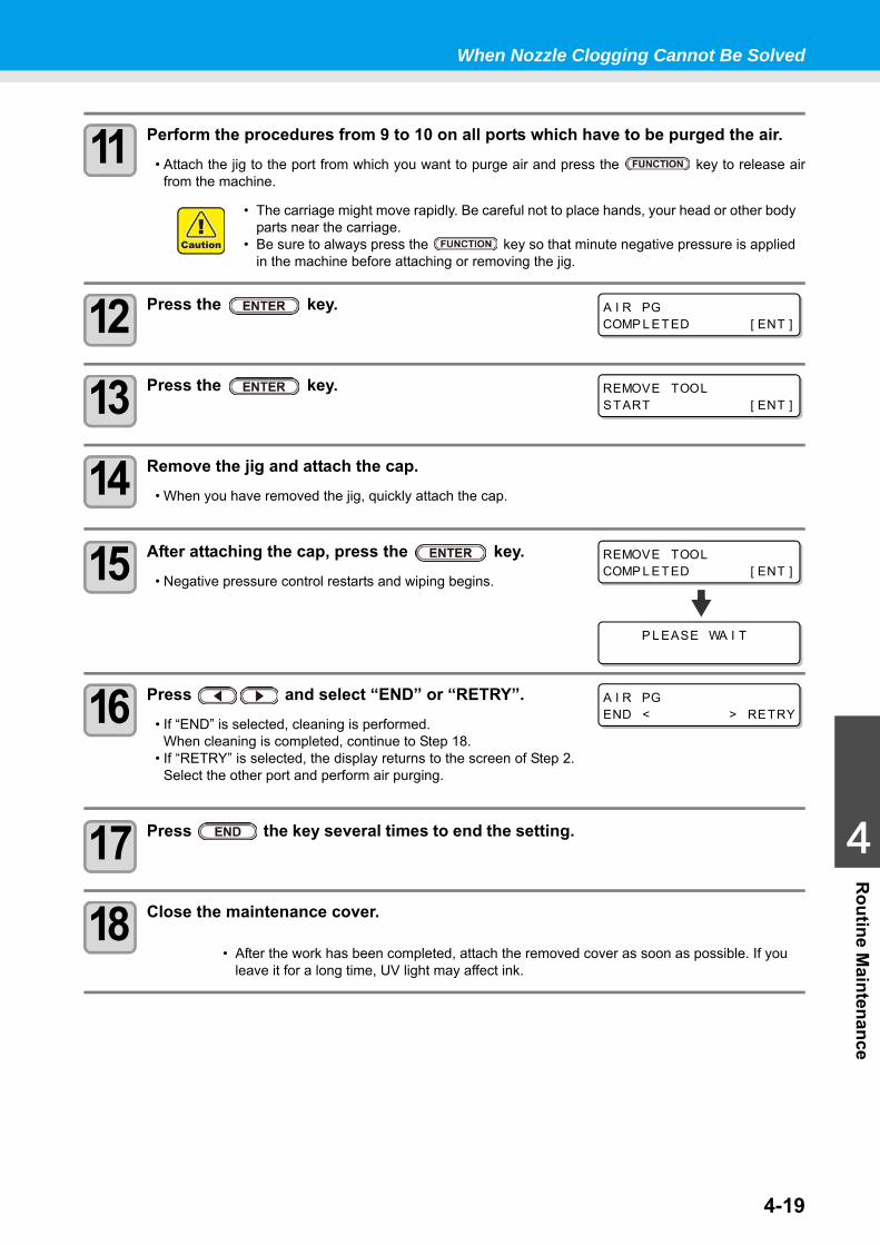
When Nozzle Clogging Cannot Be Solved
4-19
1
1
1
4
Routine M
aintenance
11 Perform the procedures from 9 to 10 on all ports which have to be purged the air. • Attach the jig to the port from which you want to purge air and press the key to release air
from the machine.
12 Press the key.
13 Press the key.
14 Remove the jig and attach the cap.• When you have removed the jig, quickly attach the cap.
15 After attaching the cap, press the key.• Negative pressure control restarts and wiping begins.
16 Press and select “END” or “RETRY”.• If “END” is selected, cleaning is performed.
When cleaning is completed, continue to Step 18.• If “RETRY” is selected, the display returns to the screen of Step 2.
Select the other port and perform air purging.
17 Press the key several times to end the setting.
18 Close the maintenance cover.
• The carriage might move rapidly. Be careful not to place hands, your head or other body parts near the carriage.
• Be sure to always press the key so that minute negative pressure is applied in the machine before attaching or removing the jig.
• After the work has been completed, attach the removed cover as soon as possible. If you leave it for a long time, UV light may affect ink.
A I R PGCOMP L ETED [ ENT ]
REMOVE TOOLSTART [ ENT ]
REMOVE TOOLCOMP L ETED [ ENT ]
P L EASE WA I T
A I R PGEND < > RETRY
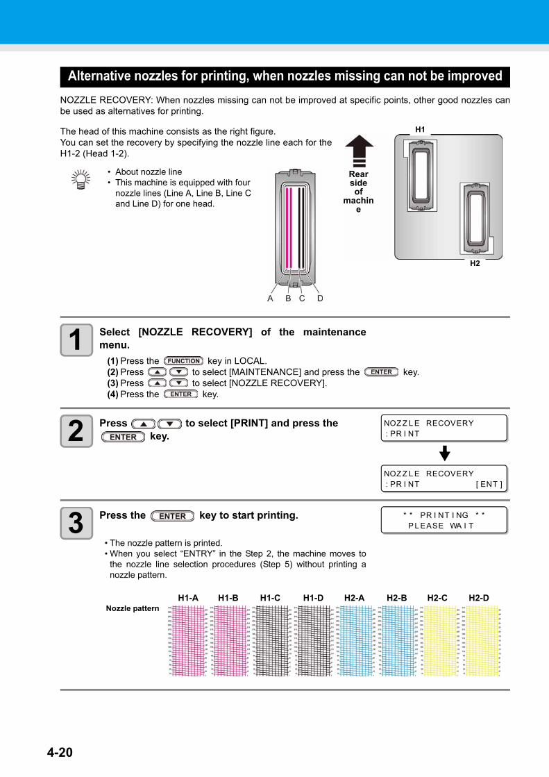
4-20
Alternative nozzles for printing, when nozzles missing can not be improvedNOZZLE RECOVERY: When nozzles missing can not be improved at specific points, other good nozzles canbe used as alternatives for printing.
The head of this machine consists as the right figure.You can set the recovery by specifying the nozzle line each for theH1-2 (Head 1-2).
1 Select [NOZZLE RECOVERY] of the maintenancemenu.
(1) Press the key in LOCAL.(2) Press to select [MAINTENANCE] and press the key.(3) Press to select [NOZZLE RECOVERY].(4) Press the key.
2 Press to select [PRINT] and press the key.
3 Press the key to start printing.
• The nozzle pattern is printed.• When you select “ENTRY” in the Step 2, the machine moves to
the nozzle line selection procedures (Step 5) without printing anozzle pattern.
• About nozzle line• This machine is equipped with four
nozzle lines (Line A, Line B, Line C and Line D) for one head.
Rear side of
machine
H1
H2
NOZ Z L E RECOVERY: PR I NT
NOZ Z L E RECOVERY: PR I NT [ ENT ]
* * PR I NT I NG * *P L EASE WA I T
Nozzle patternH1-A H1-D H2-A H2-CH1-B H1-C H2-B H2-D
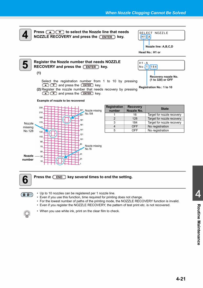
When Nozzle Clogging Cannot Be Solved
4-21
1
1
1
4
Routine M
aintenance
4 Press to select the Nozzle line that needs NOZZLE RECOVERY and press the key.
5 Register the Nozzle number that needs NOZZLE RECOVERY and press the key.
(1)
Select the registration number from 1 to 10 by pressing and press the key.
(2) Register the nozzle number that needs recovery by pressing and press the key.
6 Press the key several times to end the setting.
• Up to 10 nozzles can be registered per 1 nozzle line.• Even if you use this function, time required for printing does not change.• For the lowest number of paths of the printing mode, the NOZZLE RECOVERY function is invalid.• Even if you register the NOZZLE RECOVERY, the pattern of test print etc. is not recovered.
• When you use white ink, print on the clear film to check.
SE L ECT NOZ Z L E: H1 - A
Head No.: H1 or
Nozzle line: A,B,C,D
H1 - ANo . 1 : 1 8 4
Registration No.: 1 to 10
Recovery nozzle No. (1 to 320) or OFF
Nozzle missingNo.184
Nozzlenumber
Nozzle missingNo.16
NozzlemissingNo.128
Registration number
Recovery Nozzle No. State
1 16 Target for nozzle recovery2 128 Target for nozzle recovery3 184 Target for nozzle recovery4 OFF No registration5 OFF No registration
Example of nozzle to be recovered
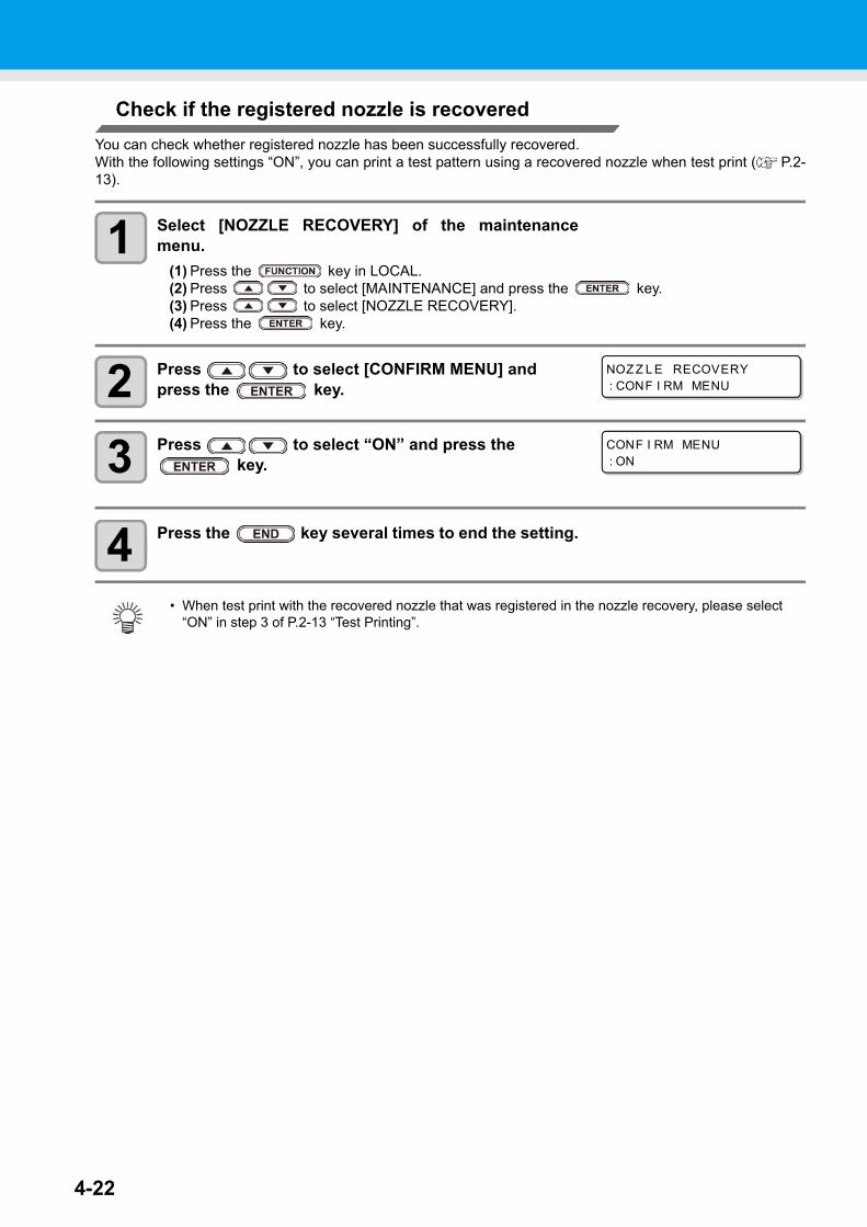
4-22
Check if the registered nozzle is recoveredYou can check whether registered nozzle has been successfully recovered.With the following settings “ON”, you can print a test pattern using a recovered nozzle when test print ( P.2-13).
1 Select [NOZZLE RECOVERY] of the maintenancemenu.
(1) Press the key in LOCAL.(2) Press to select [MAINTENANCE] and press the key.(3) Press to select [NOZZLE RECOVERY].(4) Press the key.
2 Press to select [CONFIRM MENU] and press the key.
3 Press to select “ON” and press the key.
4 Press the key several times to end the setting.
• When test print with the recovered nozzle that was registered in the nozzle recovery, please select “ON” in step 3 of P.2-13 “Test Printing”.
NOZ Z L E RECOVERY: CONF I RM MENU
CONF I RM MENU: ON
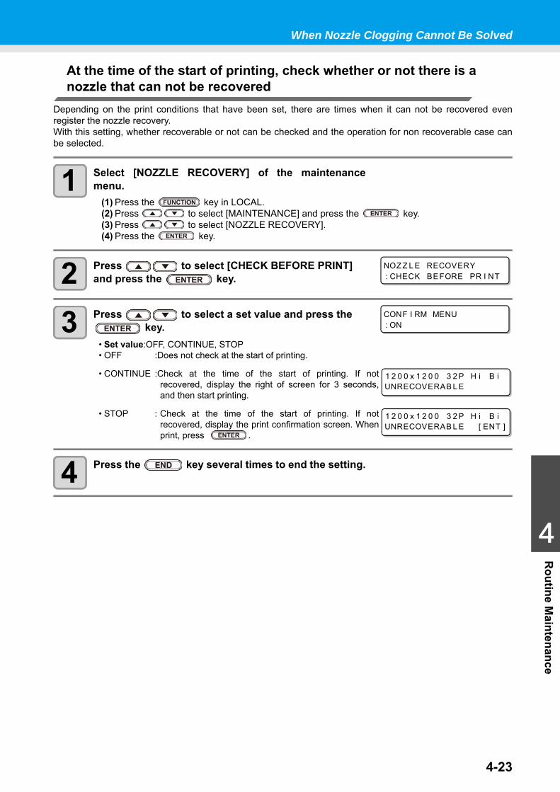
When Nozzle Clogging Cannot Be Solved
4-23
1
1
1
4
Routine M
aintenance
At the time of the start of printing, check whether or not there is a nozzle that can not be recovered
Depending on the print conditions that have been set, there are times when it can not be recovered evenregister the nozzle recovery.With this setting, whether recoverable or not can be checked and the operation for non recoverable case canbe selected.
1 Select [NOZZLE RECOVERY] of the maintenancemenu.
(1) Press the key in LOCAL.(2) Press to select [MAINTENANCE] and press the key.(3) Press to select [NOZZLE RECOVERY].(4) Press the key.
2 Press to select [CHECK BEFORE PRINT] and press the key.
3 Press to select a set value and press the key.
• Set value:OFF, CONTINUE, STOP• OFF :Does not check at the start of printing.
• CONTINUE :Check at the time of the start of printing. If notrecovered, display the right of screen for 3 seconds,and then start printing.
• STOP : Check at the time of the start of printing. If notrecovered, display the print confirmation screen. Whenprint, press .
4 Press the key several times to end the setting.
NOZ Z L E RECOVERY: CHECK BEFORE PR I NT
CONF I RM MENU: ON
1 2 0 0 x 1 2 0 0 3 2 P H i B iUNRECOVERAB L E
1 2 0 0 x 1 2 0 0 3 2 P H i B iUNRECOVERAB L E [ ENT ]
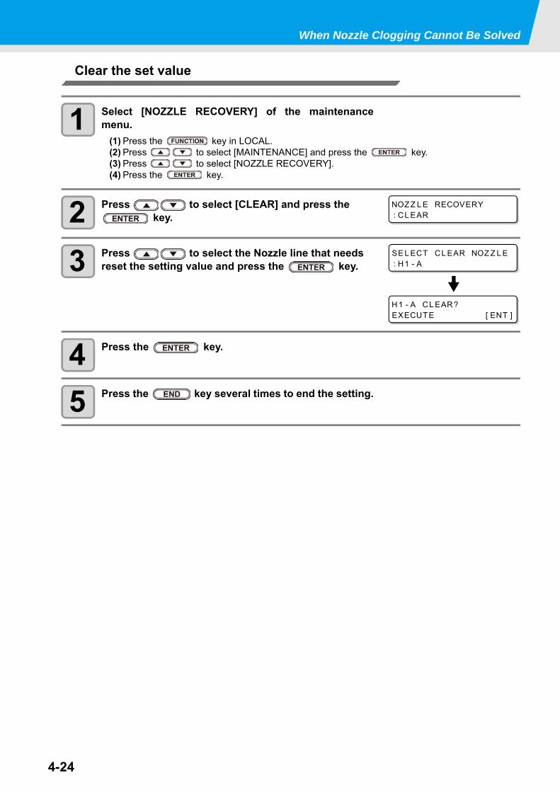
When Nozzle Clogging Cannot Be Solved
4-24
Clear the set value
1 Select [NOZZLE RECOVERY] of the maintenancemenu.
(1) Press the key in LOCAL.(2) Press to select [MAINTENANCE] and press the key.(3) Press to select [NOZZLE RECOVERY].(4) Press the key.
2 Press to select [CLEAR] and press the key.
3 Press to select the Nozzle line that needs reset the setting value and press the key.
4 Press the key.
5 Press the key several times to end the setting.
NOZ Z L E RECOVERY: CL EAR
SE L ECT CL EAR NOZ Z L E: H1 - A
H1 - A CL EAR?EXECUTE [ ENT ]
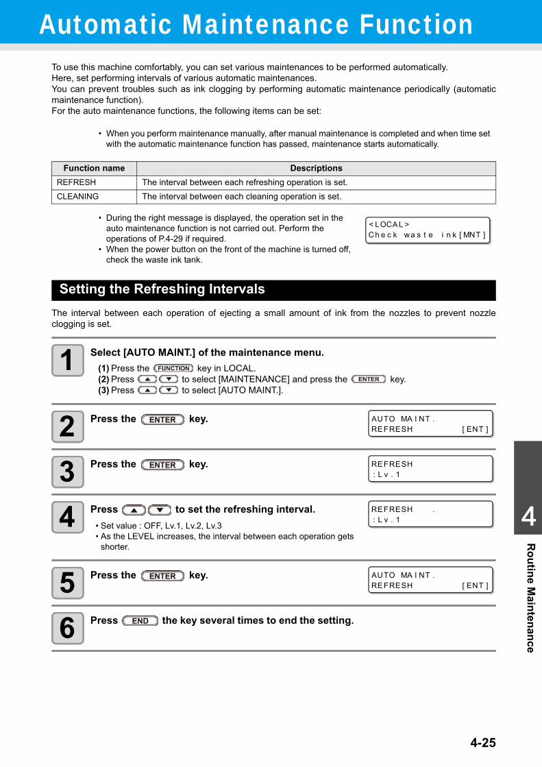
4-25
1
1
1
4
Routine M
aintenanceAutomatic Maintenance Function
To use this machine comfortably, you can set various maintenances to be performed automatically.Here, set performing intervals of various automatic maintenances.You can prevent troubles such as ink clogging by performing automatic maintenance periodically (automaticmaintenance function).For the auto maintenance functions, the following items can be set:
Setting the Refreshing IntervalsThe interval between each operation of ejecting a small amount of ink from the nozzles to prevent nozzleclogging is set.
1 Select [AUTO MAINT.] of the maintenance menu.(1) Press the key in LOCAL.(2) Press to select [MAINTENANCE] and press the key.(3) Press to select [AUTO MAINT.].
2 Press the key.
3 Press the key.
4 Press to set the refreshing interval.• Set value : OFF, Lv.1, Lv.2, Lv.3• As the LEVEL increases, the interval between each operation gets
shorter.
5 Press the key.
6 Press the key several times to end the setting.
• When you perform maintenance manually, after manual maintenance is completed and when time set with the automatic maintenance function has passed, maintenance starts automatically.
Function name DescriptionsREFRESH The interval between each refreshing operation is set.CLEANING The interval between each cleaning operation is set.
• During the right message is displayed, the operation set in the auto maintenance function is not carried out. Perform the operations of P.4-29 if required.
• When the power button on the front of the machine is turned off, check the waste ink tank.
< LOCA L >Ch e c k wa s t e i n k [ MNT ]
AUTO MA I NT .REFRESH [ ENT ]
REFRESH: L v . 1
REFRESH .: L v . 1
AUTO MA I NT .REFRESH [ ENT ]
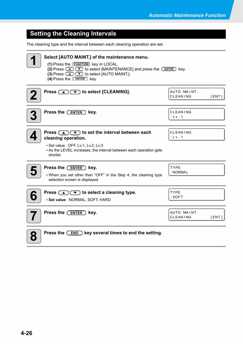
Automatic Maintenance Function
4-26
Setting the Cleaning IntervalsThe cleaning type and the interval between each cleaning operation are set.
1 Select [AUTO MAINT.] of the maintenance menu.(1) Press the key in LOCAL.(2) Press to select [MAINTENANCE] and press the key.(3) Press to select [AUTO MAINT.].(4) Press the key.
2 Press to select [CLEANING].
3 Press the key.
4 Press to set the interval between each cleaning operation.
• Set value : OFF, Lv.1, Lv.2, Lv.3• As the LEVEL increases, the interval between each operation gets
shorter.
5 Press the key.• When you set other than “OFF” in the Step 4, the cleaning type
selection screen is displayed.
6 Press to select a cleaning type.• Set value : NORMAL, SOFT, HARD
7 Press the key.
8 Press the key several times to end the setting.
AUTO MA I NT .CL EAN I NG [ ENT ]
CL EAN I NG: L v . 1
CL EAN I NG: L v . 1
TYPE: NORMA L
TYPE: SOF T
AUTO MA I NT .CL EAN I NG [ ENT ]
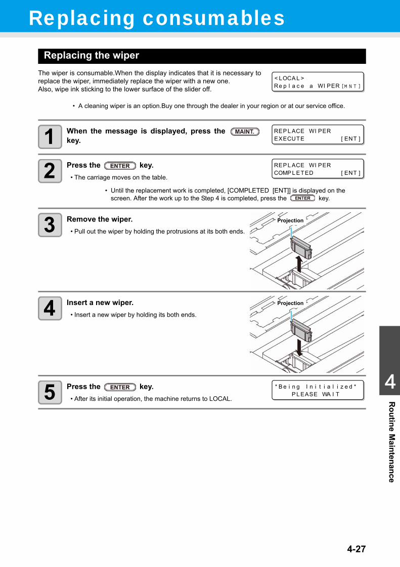
4-27
1
1
1
4
Routine M
aintenanceReplacing consumables
Replacing the wiperThe wiper is consumable.When the display indicates that it is necessary toreplace the wiper, immediately replace the wiper with a new one.Also, wipe ink sticking to the lower surface of the slider off.
1 When the message is displayed, press the key.
2 Press the key.• The carriage moves on the table.
3 Remove the wiper.• Pull out the wiper by holding the protrusions at its both ends.
4 Insert a new wiper.• Insert a new wiper by holding its both ends.
5 Press the key.• After its initial operation, the machine returns to LOCAL.
• A cleaning wiper is an option.Buy one through the dealer in your region or at our service office.
• Until the replacement work is completed, [COMPLETED [ENT]] is displayed on the screen. After the work up to the Step 4 is completed, press the key.
< LOCA L >Re p l a c e a WI PER [ MN T ]
REP L ACE WI PEREXECUTE [ ENT ]
REP L ACE WI PERCOMP L ETED [ ENT ]
Projection
Projection
* B e i n g I n i t i a l i z e d *P L EASE WA I T
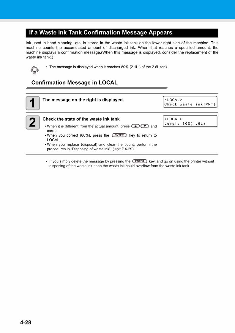
4-28
If a Waste Ink Tank Confirmation Message AppearsInk used in head cleaning, etc. is stored in the waste ink tank on the lower right side of the machine. Thismachine counts the accumulated amount of discharged ink. When that reaches a specified amount, themachine displays a confirmation message.(When this message is displayed, consider the replacement of thewaste ink tank.)
Confirmation Message in LOCAL
1 The message on the right is displayed.
2 Check the state of the waste ink tank• When it is different from the actual amount, press and
correct.• When you correct (80%), press the key to return to
LOCAL.• When you replace (disposal) and clear the count, perform the
procedures in “Disposing of waste ink”. ( P.4-29)
• The message is displayed when it reaches 80% (2.1L ) of the 2.6L tank.
• If you simply delete the message by pressing the key, and go on using the printer without disposing of the waste ink, then the waste ink could overflow from the waste ink tank.
< LOCA L >Ch e c k wa s t e i n k [ MNT ]
< LOCA L >L e v e l : 8 0%( 1 . 6 L )
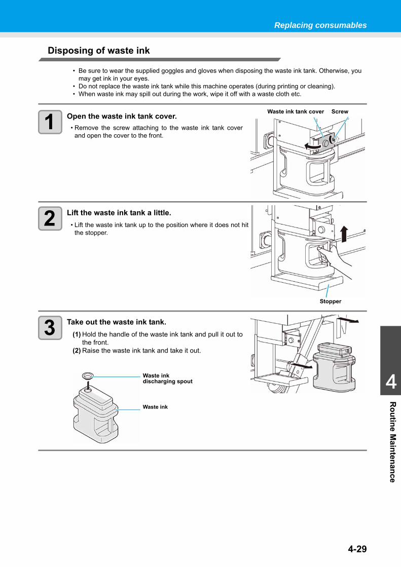
Replacing consumables
4-29
1
1
1
4
Routine M
aintenance
Disposing of waste ink
1 Open the waste ink tank cover.• Remove the screw attaching to the waste ink tank cover
and open the cover to the front.
2 Lift the waste ink tank a little.• Lift the waste ink tank up to the position where it does not hit
the stopper.
3 Take out the waste ink tank.(1) Hold the handle of the waste ink tank and pull it out to
the front.(2) Raise the waste ink tank and take it out.
• Be sure to wear the supplied goggles and gloves when disposing the waste ink tank. Otherwise, you may get ink in your eyes.
• Do not replace the waste ink tank while this machine operates (during printing or cleaning).• When waste ink may spill out during the work, wipe it off with a waste cloth etc.
Waste ink tank cover Screw
Stopper
Waste ink
Waste ink discharging spout
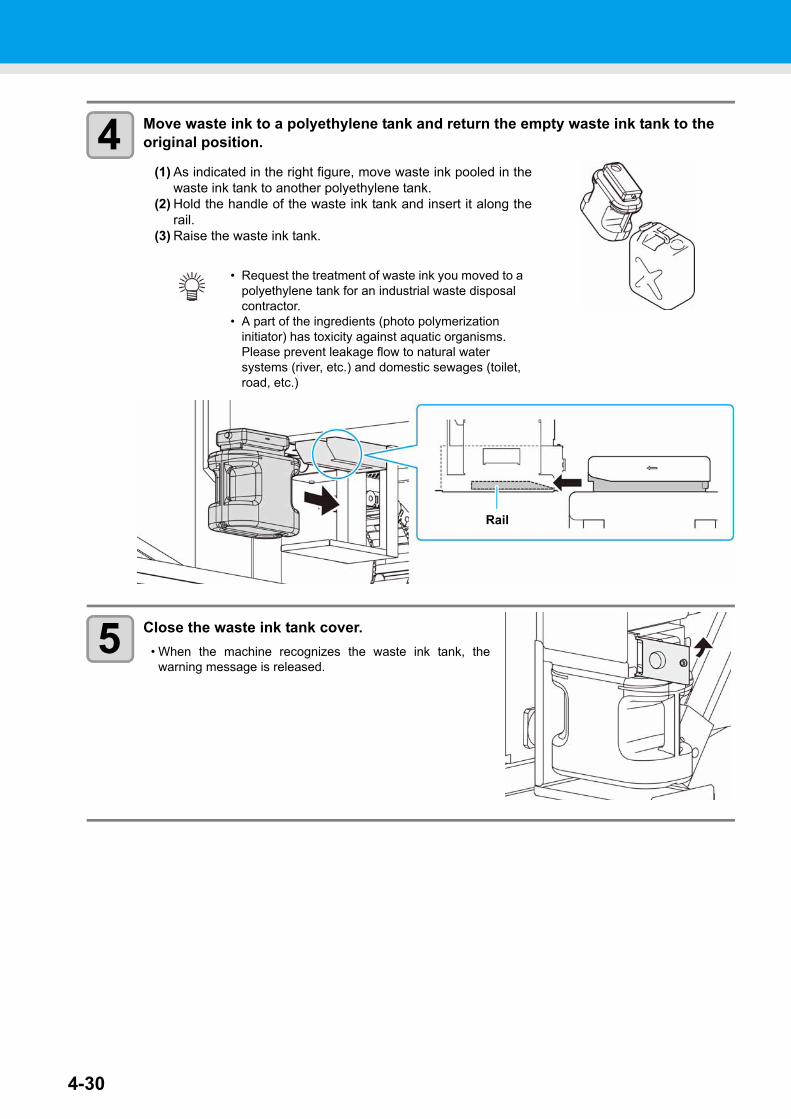
4-30
4 Move waste ink to a polyethylene tank and return the empty waste ink tank to the original position.
(1) As indicated in the right figure, move waste ink pooled in thewaste ink tank to another polyethylene tank.
(2) Hold the handle of the waste ink tank and insert it along therail.
(3) Raise the waste ink tank.
5 Close the waste ink tank cover.• When the machine recognizes the waste ink tank, the
warning message is released.
• Request the treatment of waste ink you moved to a polyethylene tank for an industrial waste disposal contractor.
• A part of the ingredients (photo polymerization initiator) has toxicity against aquatic organisms. Please prevent leakage flow to natural water systems (river, etc.) and domestic sewages (toilet, road, etc.)
Rail
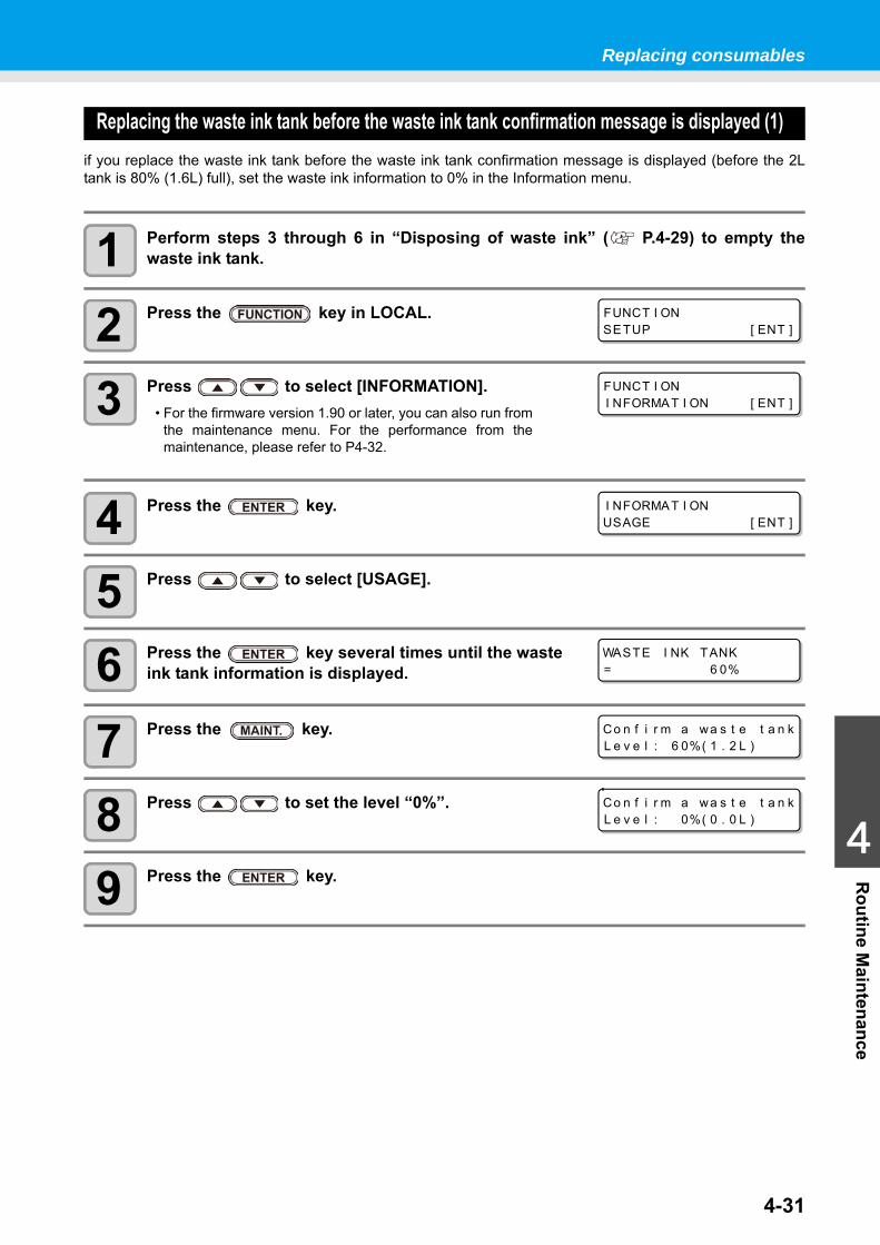
Replacing consumables
4-31
1
1
1
4
Routine M
aintenance
Replacing the waste ink tank before the waste ink tank confirmation message is displayed (1)if you replace the waste ink tank before the waste ink tank confirmation message is displayed (before the 2Ltank is 80% (1.6L) full), set the waste ink information to 0% in the Information menu.
1 Perform steps 3 through 6 in “Disposing of waste ink” ( P.4-29) to empty thewaste ink tank.
2 Press the key in LOCAL.
3 Press to select [INFORMATION].• For the firmware version 1.90 or later, you can also run from
the maintenance menu. For the performance from themaintenance, please refer to P4-32.
4 Press the key.
5 Press to select [USAGE].
6 Press the key several times until the waste ink tank information is displayed.
7 Press the key.
8 Press to set the level “0%”.
9 Press the key.
FUNCT I ONSETUP [ ENT ]
FUNCT I ONI NFORMAT I ON [ ENT ]
I NFORMAT I ONUSAGE [ ENT ]
WASTE I NK TANK= 6 0%
Co n f i r m a wa s t e t a n kL e v e l : 6 0%( 1 . 2 L )
Co n f i r m a wa s t e t a n kL e v e l : 0%( 0 . 0 L )
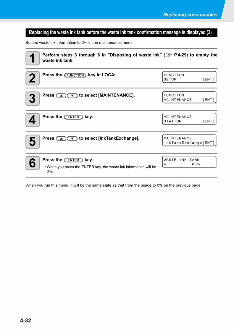
Replacing consumables
4-32
Replacing the waste ink tank before the waste ink tank confirmation message is displayed (2)Set the waste ink information to 0% in the maintenance menu.
1 Perform steps 3 through 6 in "Disposing of waste ink" ( P.4-29) to empty thewaste ink tank.
2 Press the key in LOCAL.
3 Press to select [MAINTENANCE].
4 Press the key.
5 Press to select [InkTankExchange].
6 Press the key. • When you press the ENTER key, the waste ink information will be
0%.
When you run this menu, it will be the same state as that from the usage to 0% on the previous page.
FUNCT I ONSETUP [ ENT ]
FUNCT I ONMA I NTENANCE [ ENT ]
MA I NTENANCESTAT I ON [ ENT ]
MA I NTENANCEI n k T a n k E x c h a n g e [ ENT ]
WASTE I NK TANK= 6 0%
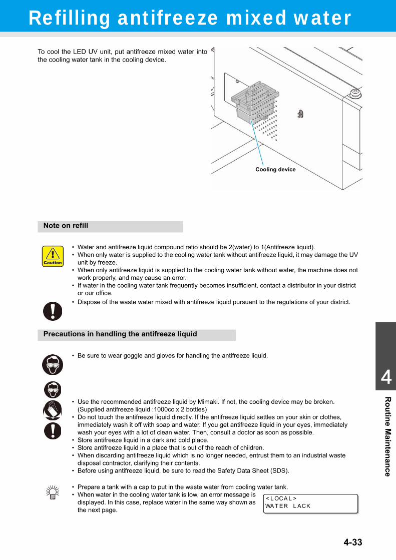
4-33
1
1
1
4
Routine M
aintenanceRefilling antifreeze mixed water
To cool the LED UV unit, put antifreeze mixed water intothe cooling water tank in the cooling device.
Note on refill
Precautions in handling the antifreeze liquid
• Water and antifreeze liquid compound ratio should be 2(water) to 1(Antifreeze liquid).• When only water is supplied to the cooling water tank without antifreeze liquid, it may damage the UV
unit by freeze.• When only antifreeze liquid is supplied to the cooling water tank without water, the machine does not
work properly, and may cause an error.• If water in the cooling water tank frequently becomes insufficient, contact a distributor in your district
or our office.• Dispose of the waste water mixed with antifreeze liquid pursuant to the regulations of your district.
• Be sure to wear goggle and gloves for handling the antifreeze liquid.
• Use the recommended antifreeze liquid by Mimaki. If not, the cooling device may be broken. (Supplied antifreeze liquid :1000cc x 2 bottles)
• Do not touch the antifreeze liquid directly. If the antifreeze liquid settles on your skin or clothes, immediately wash it off with soap and water. If you get antifreeze liquid in your eyes, immediately wash your eyes with a lot of clean water. Then, consult a doctor as soon as possible.
• Store antifreeze liquid in a dark and cold place.• Store antifreeze liquid in a place that is out of the reach of children.• When discarding antifreeze liquid which is no longer needed, entrust them to an industrial waste
disposal contractor, clarifying their contents.• Before using antifreeze liquid, be sure to read the Safety Data Sheet (SDS).
• Prepare a tank with a cap to put in the waste water from cooling water tank.• When water in the cooling water tank is low, an error message is
displayed. In this case, replace water in the same way shown as the next page.
Cooling device
< LOCA L >WA T ER L ACK
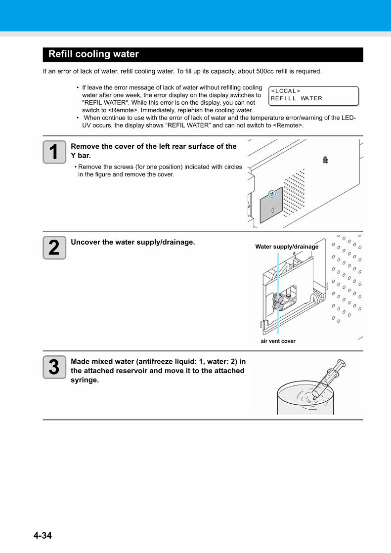
4-34
Refill cooling waterIf an error of lack of water, refill cooling water. To fill up its capacity, about 500cc refill is required.
1 Remove the cover of the left rear surface of theY bar.
• Remove the screws (for one position) indicated with circlesin the figure and remove the cover.
2 Uncover the water supply/drainage.
3 Made mixed water (antifreeze liquid: 1, water: 2) in the attached reservoir and move it to the attached syringe.
• If leave the error message of lack of water without refilling cooling water after one week, the error display on the display switches to "REFIL WATER". While this error is on the display, you can not switch to <Remote>. Immediately, replenish the cooling water.
• When continue to use with the error of lack of water and the temperature error/warning of the LED-UV occurs, the display shows “REFIL WATER” and can not switch to <Remote>.
< LOCA L >REF I L L WATER
air vent cover
Water supply/drainage
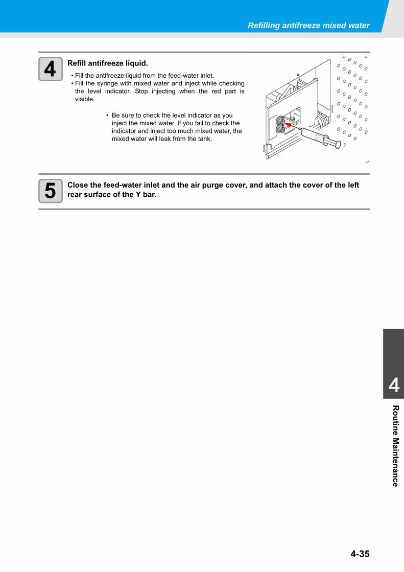
Refilling antifreeze mixed water
4-35
1
1
1
4
Routine M
aintenance
4 Refill antifreeze liquid.• Fill the antifreeze liquid from the feed-water inlet.• Fill the syringe with mixed water and inject while checking
the level indicator. Stop injecting when the red part isvisible.
5 Close the feed-water inlet and the air purge cover, and attach the cover of the left rear surface of the Y bar.
• Be sure to check the level indicator as you inject the mixed water. If you fail to check the indicator and inject too much mixed water, the mixed water will leak from the tank.
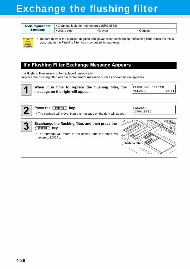
4-36
Exchange the flushing filter
If a Flushing Filter Exchange Message AppearsThe flushing filter needs to be replaced periodically.Replace the flushing filter when a replacement message such as shown below appears.
1 When it is time to replace the flushing filter, themessage on the right will appear.
2 Press the key.• The carriage will move, then the message on the right will appear.
3 Excahange the flushing filter, and then press the key.
• The carriage will return to the station, and the mode willreturn to LOCAL.
Tools required for Exchabge
• Cleaning liquid for maintenance (SPC-0568)• Waste cloth • Gloves • Goggles
• Be sure to wear the supplied goggles and gloves when exchanging theflushing filter. Since the ink is absorbed in the Flushing filter, you may get ink in your eyes.
F LUSH I NG F I L TERP L EASE [ ENT ]
EXCANGECOMP L ETED
Flushinu filter
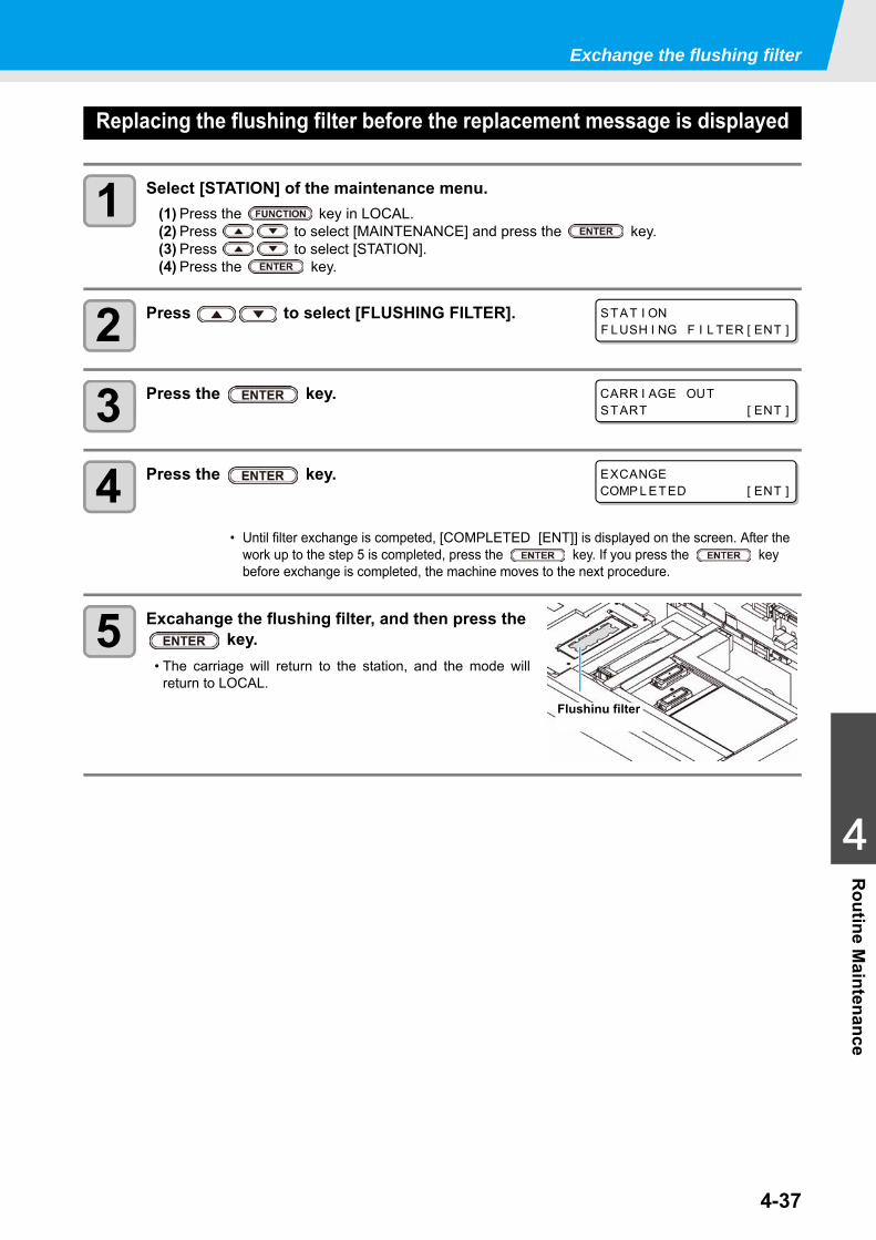
Exchange the flushing filter
4-37
1
1
1
4
Routine M
aintenance
Replacing the flushing filter before the replacement message is displayed
1 Select [STATION] of the maintenance menu.(1) Press the key in LOCAL.(2) Press to select [MAINTENANCE] and press the key.(3) Press to select [STATION].(4) Press the key.
2 Press to select [FLUSHING FILTER].
3 Press the key.
4 Press the key.
5 Excahange the flushing filter, and then press the key.
• The carriage will return to the station, and the mode willreturn to LOCAL.
• Until filter exchange is competed, [COMPLETED [ENT]] is displayed on the screen. After the work up to the step 5 is completed, press the key. If you press the key before exchange is completed, the machine moves to the next procedure.
STAT I ONF LUSH I NG F I L TER [ ENT ]
CARR I AGE OUTSTART [ ENT ]
EXCANGECOMP L ETED [ ENT ]
Flushinu filter

4-38
This chapter
describes the corrective measures to be taken for a phenomenon suspected to be trou-ble and the procedures to clear the error number displayed on the LCD.
Troubleshooting ...............................................................................5-2Power does not turn on ...................................................................5-2The machine does not start printing ................................................5-2Image quality is poor .......................................................................5-3Nozzle is clogged ............................................................................5-3Ink bottle warning appears ..............................................................5-4If a Message “SHAKE WHITE INK BOTLES” Appears ...................5-5If an error related to the sub tank occurs (Error 618 to 61b) ...........5-6If negative pressure abnormality occurs ..........................................5-7
Warning / Error Messages ...............................................................5-9Warning messages ..........................................................................5-9Error messages .............................................................................5-12
Chapter 5Troubleshooting
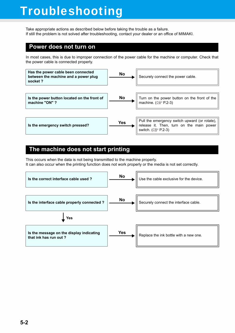
5-2
TroubleshootingTake appropriate actions as described below before taking the trouble as a failure.If still the problem is not solved after troubleshooting, contact your dealer or an office of MIMAKI.
Power does not turn onIn most cases, this is due to improper connection of the power cable for the machine or computer. Check thatthe power cable is connected properly.
The machine does not start printingThis occurs when the data is not being transmitted to the machine properly.It can also occur when the printing function does not work properly or the media is not set correctly.
Has the power cable been connected between the machine and a power plug socket ?
Securely connect the power cable.
Is the power button located on the front of machine "ON" ?
Turn on the power button on the front of themachine. ( P.2-3)
Is the emergency switch pressed?Pull the emergency switch upward (or rotate),release it. Then, turn on the main powerswitch. ( P.2-3)
Is the correct interface cable used ? Use the cable exclusive for the device.
Is the interface cable properly connected ? Securely connect the interface cable.
Yes
Is the message on the display indicating that ink has run out ? Replace the ink bottle with a new one.
No
No
Yes
No
No
Yes
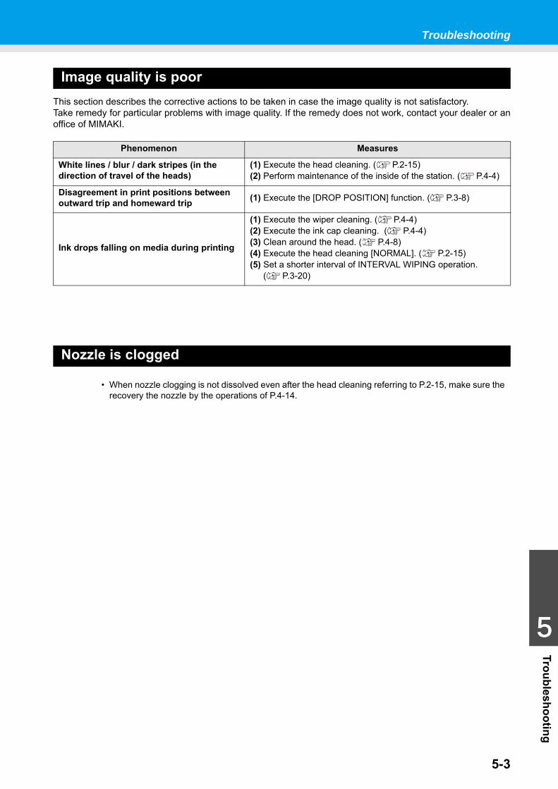
Troubleshooting
5-3
1
1
1
1
5
Troubleshooting
Image quality is poorThis section describes the corrective actions to be taken in case the image quality is not satisfactory.Take remedy for particular problems with image quality. If the remedy does not work, contact your dealer or anoffice of MIMAKI.
Nozzle is clogged
Phenomenon Measures
White lines / blur / dark stripes (in the direction of travel of the heads)
(1) Execute the head cleaning. ( P.2-15)(2) Perform maintenance of the inside of the station. ( P.4-4)
Disagreement in print positions between outward trip and homeward trip (1) Execute the [DROP POSITION] function. ( P.3-8)
Ink drops falling on media during printing
(1) Execute the wiper cleaning. ( P.4-4)(2) Execute the ink cap cleaning. ( P.4-4)(3) Clean around the head. ( P.4-8)(4) Execute the head cleaning [NORMAL]. ( P.2-15)(5) Set a shorter interval of INTERVAL WIPING operation.
( P.3-20)
• When nozzle clogging is not dissolved even after the head cleaning referring to P.2-15, make sure the recovery the nozzle by the operations of P.4-14.
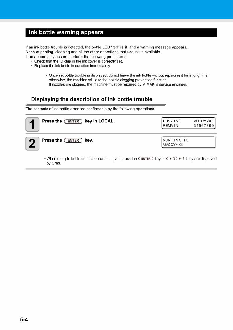
5-4
Ink bottle warning appears
If an ink bottle trouble is detected, the bottle LED “red” is lit, and a warning message appears.None of printing, cleaning and all the other operations that use ink is available.If an abnormality occurs, perform the following procedures:
• Check that the IC chip in the ink cover is correctly set.• Replace the ink bottle in question immediately.
Displaying the description of ink bottle troubleThe contents of ink bottle error are confirmable by the following operations.
1 Press the key in LOCAL.
2 Press the key.
• When multiple bottle defects occur and if you press the key or , they are displayedby turns.
• Once ink bottle trouble is displayed, do not leave the ink bottle without replacing it for a long time; otherwise, the machine will lose the nozzle clogging prevention function.If nozzles are clogged, the machine must be repaired by MIMAKI's service engineer.
LUS - 1 5 0 MMCCYYKKREMA I N 3 4 5 6 7 8 9 9
NON I NK I CMMCCYYKK
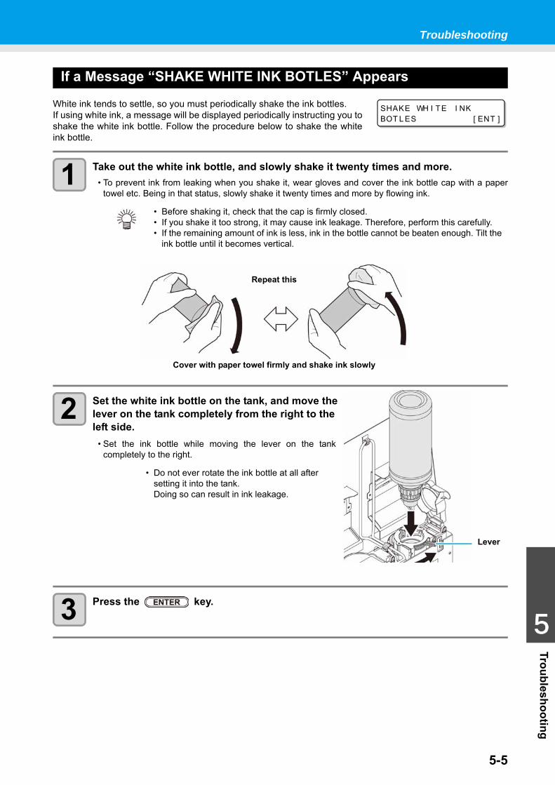
Troubleshooting
5-5
1
1
1
1
5
Troubleshooting
If a Message “SHAKE WHITE INK BOTLES” Appears
White ink tends to settle, so you must periodically shake the ink bottles.If using white ink, a message will be displayed periodically instructing you toshake the white ink bottle. Follow the procedure below to shake the whiteink bottle.
1 Take out the white ink bottle, and slowly shake it twenty times and more.• To prevent ink from leaking when you shake it, wear gloves and cover the ink bottle cap with a paper
towel etc. Being in that status, slowly shake it twenty times and more by flowing ink.
2 Set the white ink bottle on the tank, and move the lever on the tank completely from the right to the left side.
• Set the ink bottle while moving the lever on the tankcompletely to the right.
3 Press the key.
• Before shaking it, check that the cap is firmly closed.• If you shake it too strong, it may cause ink leakage. Therefore, perform this carefully.• If the remaining amount of ink is less, ink in the bottle cannot be beaten enough. Tilt the
ink bottle until it becomes vertical.
• Do not ever rotate the ink bottle at all after setting it into the tank. Doing so can result in ink leakage.
SHAKE WH I TE I NKBOT L ES [ ENT ]
Cover with paper towel firmly and shake ink slowly
Repeat this
Lever
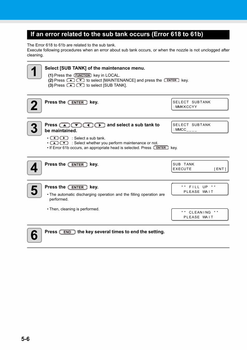
5-6
If an error related to the sub tank occurs (Error 618 to 61b)The Error 618 to 61b are related to the sub tank.Execute following procedures when an error about sub tank occurs, or when the nozzle is not unclogged aftercleaning.
1 Select [SUB TANK] of the maintenance menu.(1) Press the key in LOCAL.(2) Press to select [MAINTENANCE] and press the key.(3) Press to select [SUB TANK].
2 Press the key.
3 Press and select a sub tank to be maintained.
• : Select a sub tank.• : Select whether you perform maintenance or not.• If Error 61b occurs, an appropriate head is selected. Press key.
4 Press the key.
5 Press the key.• The automatic discharging operation and the filling operation are
performed.
• Then, cleaning is performed.
6 Press the key several times to end the setting.
SE L ECT SUBTANK: MMKKCCYY
SE L ECT SUBTANK: MMCC_ _ _ _
SUB TANKEXECUTE [ ENT ]
* * F I L L UP * *P L EASE WA I T
* * CL EAN I NG * *P L EASE WA I T
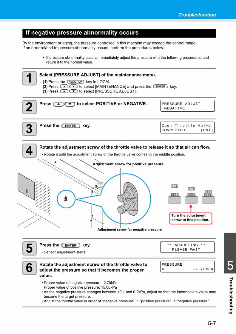
Troubleshooting
5-7
1
1
1
1
5
Troubleshooting
If negative pressure abnormality occursBy the environment or aging, the pressure controlled in this machine may exceed the control range. If an error related to pressure abnormality occurs, perform the procedures below:
1 Select [PRESSURE ADJUST] of the maintenance menu.(1) Press the key in LOCAL.(2) Press to select [MAINTENANCE] and press the key.(3) Press to select [PRESSURE ADJUST].
2 Press to select POSITIVE or NEGATIVE.
3 Press the key.
4 Rotate the adjustment screw of the throttle valve to release it so that air can flow.• Rotate it until the adjustment screw of the throttle valve comes to the middle position.
5 Press the key.• Sensor adjustment starts.
6 Rotate the adjustment screw of the throttle valve to adjust the pressure so that it becomes the proper value.
• Proper value of negative pressure: -2.70kPaProper value of positive pressure: 15.00kPa
• As the negative pressure changes between ±0.1 and 0.2kPa, adjust so that the intermediate value maybecome the target pressure.
• Adjust the throttle valve in order of “negative pressure” “positive pressure” “negative pressure”.
• If pressure abnormality occurs, immediately adjust the pressure with the following procedures and return it to the normal value.
PRESSURE AD J UST: NEGAT I VE
Op e n T h r o t t l e V a l v eCOMP L ETED [ ENT ]
Turn the adjustment screw to this position.
Adjustment screw for positive pressure
Adjustment screw for negative pressure
* * AD J UST I NG * *P L EASE WA I T
PRESSURE= - 2 . 7 0 k P a

Troubleshooting
5-8
7 Press the key.• The error is released and the negative pressure control starts.
• When an error occurs even after you adjusted the pressure, contact your local distributor to call for service.
P L EASE WA I T
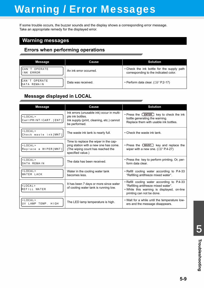
5-9
1
1
1
1
5
TroubleshootingWarning / Error Messages
If some trouble occurs, the buzzer sounds and the display shows a corresponding error message.Take an appropriate remedy for the displayed error.
Warning messages
Errors when performing operations
Message displayed in LOCAL
Message Cause Solution
An ink error occurred. • Check the ink bottle for the supply pathcorresponding to the indicated color.
Data was received. • Perform data clear. ( P.2-17)
Message Cause Solution
Ink errors (unusable ink) occur in multi-ple ink bottles.Ink supply (print, cleaning, etc.) cannot be performed.
• Press the key to check the inkbottle generating the warning. Replace them with usable ink bottles.
The waste ink tank is nearly full. • Check the waste ink tank.
Time to replace the wiper in the cap-ping station with a new one has come.(The wiping count has reached the specified value.)
• Press the key and replace thewiper with a new one. ( P.4-27)
The data has been received. • Press the key to perform printing. Or, per-form data clear.
Water in the cooling water tank becomes less.
• Refill cooling water according to P.4-33“Refilling antifreeze mixed water”.
It has been 7 days or more since water of cooling water tank is running low.
• Refill cooling water according to P.4-33“Refilling antifreeze mixed water”.
• While this warning is displayed, on-lineprinting can not be done.
The LED lamp temperature is high. • Wait for a while until the temperature low-ers and the message disappears.
C A N ‘ T OP E R A T EI N K E RROR
C A N ‘ T OP E R A T ED A T A R EMA I N
< L OC A L >C a n’ t P R I N T / C A R T . [ E N T ]
< L OC A L >C h e c k w a s t e i n k [ MN T ]
< L OC A L >R e p l a c e a W I P E R [ MN T ]
< L OC A L >D A T A R EMA I N
< L OC A L >WA T E R L A C K
< L OC A L >R E F I L L WA T E R
< L OC A L >U V L AMP T EMP . H I GH
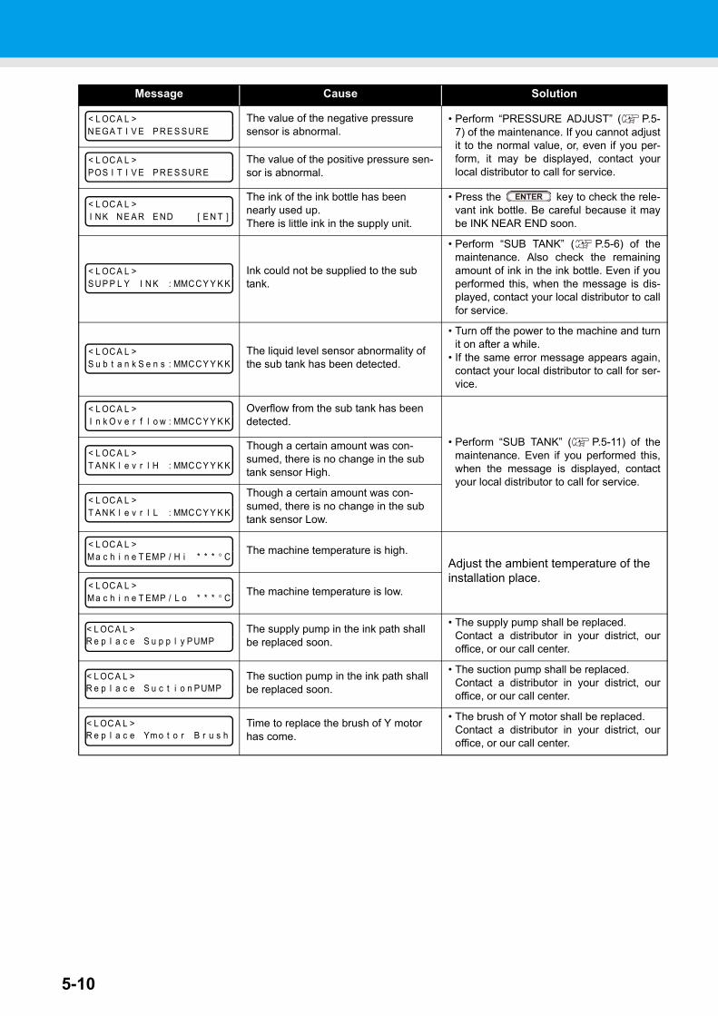
5-10
Message Cause Solution
The value of the negative pressure sensor is abnormal.
• Perform “PRESSURE ADJUST” ( P.5-7) of the maintenance. If you cannot adjustit to the normal value, or, even if you per-form, it may be displayed, contact yourlocal distributor to call for service.
The value of the positive pressure sen-sor is abnormal.
The ink of the ink bottle has been nearly used up.There is little ink in the supply unit.
• Press the key to check the rele-vant ink bottle. Be careful because it maybe INK NEAR END soon.
Ink could not be supplied to the sub tank.
• Perform “SUB TANK” ( P.5-6) of themaintenance. Also check the remainingamount of ink in the ink bottle. Even if youperformed this, when the message is dis-played, contact your local distributor to callfor service.
The liquid level sensor abnormality of the sub tank has been detected.
• Turn off the power to the machine and turnit on after a while.
• If the same error message appears again,contact your local distributor to call for ser-vice.
Overflow from the sub tank has been detected.
• Perform “SUB TANK” ( P.5-11) of themaintenance. Even if you performed this,when the message is displayed, contactyour local distributor to call for service.
Though a certain amount was con-sumed, there is no change in the sub tank sensor High.
Though a certain amount was con-sumed, there is no change in the sub tank sensor Low.
The machine temperature is high.Adjust the ambient temperature of the installation place.
The machine temperature is low.
The supply pump in the ink path shall be replaced soon.
• The supply pump shall be replaced.Contact a distributor in your district, ouroffice, or our call center.
The suction pump in the ink path shall be replaced soon.
• The suction pump shall be replaced.Contact a distributor in your district, ouroffice, or our call center.
Time to replace the brush of Y motor has come.
• The brush of Y motor shall be replaced.Contact a distributor in your district, ouroffice, or our call center.
< L OC A L >N EGA T I V E P R E S S UR E
< L OC A L >POS I T I V E P R E S S UR E
< L OC A L >I N K N E A R E ND [ E N T ]
< L OC A L >S U P P L Y I N K : MMCC Y Y K K
< L OC A L >S u b t a n k S e n s : MMCC Y Y K K
< L OC A L >I n k O v e r f l o w : MMCC Y Y K K
< L OC A L >T A N K l e v r l H : MMCC Y Y K K
< L OC A L >T A N K l e v r l L : MMCC Y Y K K
< L OC A L >M a c h i n e T EMP / H i * * * ° C
< L OC A L >M a c h i n e T EMP / L o * * * ° C
< L OC A L >R e p l a c e S u p p l y P UMP
< L OC A L >R e p l a c e S u c t i o n P UMP
< L OC A L >R e p l a c e Ym o t o r B r u s h
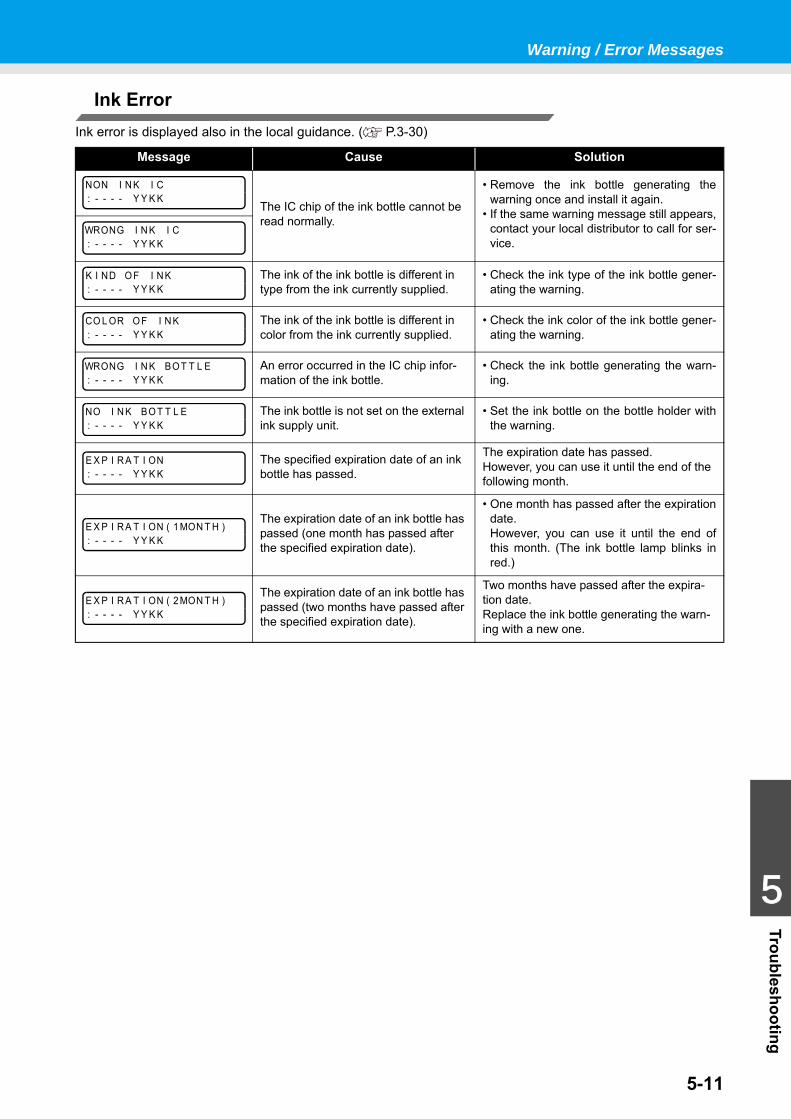
Warning / Error Messages
5-11
1
1
1
1
5
Troubleshooting
Ink ErrorInk error is displayed also in the local guidance. ( P.3-30)
Message Cause Solution
The IC chip of the ink bottle cannot be read normally.
• Remove the ink bottle generating thewarning once and install it again.
• If the same warning message still appears,contact your local distributor to call for ser-vice.
The ink of the ink bottle is different in type from the ink currently supplied.
• Check the ink type of the ink bottle gener-ating the warning.
The ink of the ink bottle is different in color from the ink currently supplied.
• Check the ink color of the ink bottle gener-ating the warning.
An error occurred in the IC chip infor-mation of the ink bottle.
• Check the ink bottle generating the warn-ing.
The ink bottle is not set on the external ink supply unit.
• Set the ink bottle on the bottle holder withthe warning.
The specified expiration date of an ink bottle has passed.
The expiration date has passed. However, you can use it until the end of the following month.
The expiration date of an ink bottle has passed (one month has passed after the specified expiration date).
• One month has passed after the expirationdate. However, you can use it until the end ofthis month. (The ink bottle lamp blinks inred.)
The expiration date of an ink bottle has passed (two months have passed after the specified expiration date).
Two months have passed after the expira-tion date. Replace the ink bottle generating the warn-ing with a new one.
NON I N K I C: - - - - Y Y K K
WRONG I N K I C: - - - - Y Y K K
K I ND O F I N K: - - - - Y Y K K
CO L OR O F I N K: - - - - Y Y K K
WRONG I N K BO T T L E: - - - - Y Y K K
NO I N K BO T T L E: - - - - Y Y K K
E X P I R A T I ON: - - - - Y Y K K
E X P I R A T I ON ( 1 MON T H ): - - - - Y Y K K
E X P I R A T I ON ( 2 MON T H ): - - - - Y Y K K
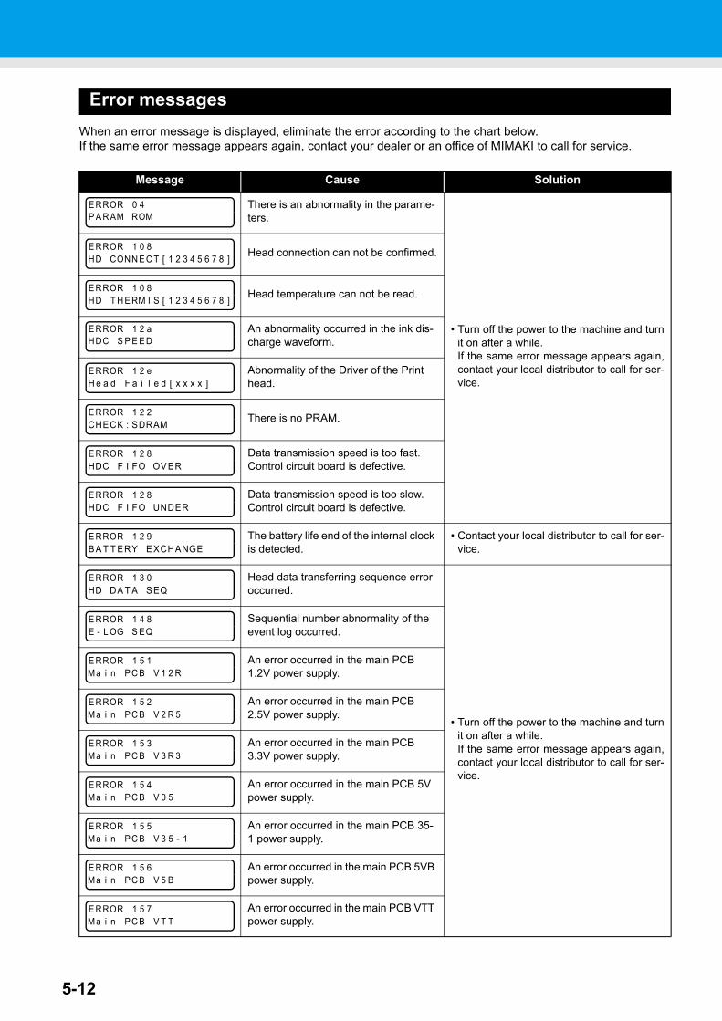
5-12
Error messagesWhen an error message is displayed, eliminate the error according to the chart below.If the same error message appears again, contact your dealer or an office of MIMAKI to call for service.
Message Cause Solution
There is an abnormality in the parame-ters.
• Turn off the power to the machine and turnit on after a while.If the same error message appears again,contact your local distributor to call for ser-vice.
Head connection can not be confirmed.
Head temperature can not be read.
An abnormality occurred in the ink dis-charge waveform.
Abnormality of the Driver of the Print head.
There is no PRAM.
Data transmission speed is too fast.Control circuit board is defective.
Data transmission speed is too slow.Control circuit board is defective.
The battery life end of the internal clock is detected.
• Contact your local distributor to call for ser-vice.
Head data transferring sequence error occurred.
• Turn off the power to the machine and turnit on after a while.If the same error message appears again,contact your local distributor to call for ser-vice.
Sequential number abnormality of the event log occurred.
An error occurred in the main PCB 1.2V power supply.
An error occurred in the main PCB 2.5V power supply.
An error occurred in the main PCB 3.3V power supply.
An error occurred in the main PCB 5V power supply.
An error occurred in the main PCB 35-1 power supply.
An error occurred in the main PCB 5VB power supply.
An error occurred in the main PCB VTT power supply.
E RROR 0 4P A R AM ROM
E RROR 1 0 8HD CONN E C T [ 1 2 3 4 5 6 7 8 ]
E RROR 1 0 8HD T H E RM I S [ 1 2 3 4 5 6 7 8 ]
E RROR 1 2 aHDC S P E E D
E RROR 1 2 eH e a d F a i l e d [ x x x x ]
E RROR 1 2 2CHECK : SDRAM
E RROR 1 2 8HDC F I FO OV ER
E RROR 1 2 8HDC F I FO UNDER
E RROR 1 2 9B A T T ERY E XCHANGE
E RROR 1 3 0HD DA T A S EQ
E RROR 1 4 8E - L OG S EQ
E RROR 1 5 1M a i n P C B V 1 2 R
E RROR 1 5 2M a i n P C B V 2 R 5
E RROR 1 5 3M a i n P C B V 3 R 3
E RROR 1 5 4M a i n P C B V 0 5
E RROR 1 5 5M a i n P C B V 3 5 - 1
E RROR 1 5 6M a i n P C B V 5 B
E RROR 1 5 7M a i n P C B V T T
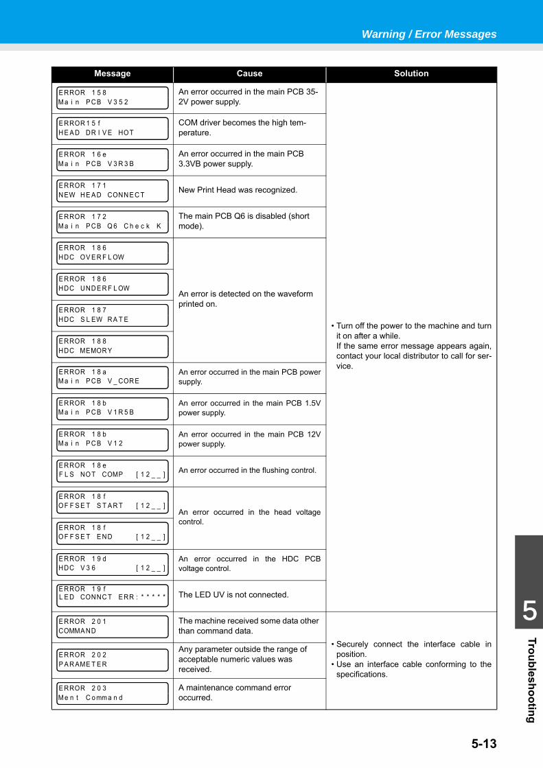
Warning / Error Messages
5-13
1
1
1
1
5
Troubleshooting
Message Cause Solution
An error occurred in the main PCB 35-2V power supply.
• Turn off the power to the machine and turnit on after a while.If the same error message appears again,contact your local distributor to call for ser-vice.
COM driver becomes the high tem-perature.
An error occurred in the main PCB 3.3VB power supply.
New Print Head was recognized.
The main PCB Q6 is disabled (short mode).
An error is detected on the waveform printed on.
An error occurred in the main PCB powersupply.
An error occurred in the main PCB 1.5Vpower supply.
An error occurred in the main PCB 12Vpower supply.
An error occurred in the flushing control.
An error occurred in the head voltagecontrol.
An error occurred in the HDC PCBvoltage control.
The LED UV is not connected.
The machine received some data other than command data.
• Securely connect the interface cable inposition.
• Use an interface cable conforming to thespecifications.
Any parameter outside the range of acceptable numeric values was received.
A maintenance command error occurred.
E RROR 1 5 8M a i n P C B V 3 5 2
E RROR 1 5 fH E A D DR I V E HO T
E RROR 1 6 eM a i n P C B V 3 R 3 B
E RROR 1 7 1N EW H E A D CONN E C T
E RROR 1 7 2M a i n P C B Q 6 C h e c k K
E RROR 1 8 6HDC OV E R F L OW
E RROR 1 8 6HDC UND E R F L OW
E RROR 1 8 7HDC S L EW R A T E
E RROR 1 8 8HDC MEMOR Y
E RROR 1 8 aM a i n P C B V _ COR E
E RROR 1 8 bM a i n P C B V 1 R 5 B
E RROR 1 8 bM a i n P C B V 1 2
E RROR 1 8 eF L S NO T COMP [ 1 2 _ _ ]
E RROR 1 8 fO F F S E T S T A R T [ 1 2 _ _ ]
E RROR 1 8 fO F F S E T E ND [ 1 2 _ _ ]
E RROR 1 9 dHDC V 3 6 [ 1 2 _ _ ]
E RROR 1 9 fL E D CONNC T E RR : * * * * *
E RROR 2 0 1COMMA ND
E RROR 2 0 2P A R AME T E R
E RROR 2 0 3M e n t C o mm a n d
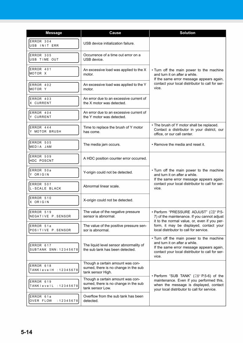
5-14
Message Cause Solution
USB device initialization failure.
• Turn off the main power to the machineand turn it on after a while.If the same error message appears again,contact your local distributor to call for ser-vice.
Occurrence of a time out error on a USB device.
An excessive load was applied to the X motor.
An excessive load was applied to the Y motor.
An error due to an excessive current of the X motor was detected.
An error due to an excessive current of the Y motor was detected.
Time to replace the brush of Y motor has come.
• The brush of Y motor shall be replaced.Contact a distributor in your district, ouroffice, or our call center.
The media jam occurs. • Remove the media and reset it.
A HDC position counter error occurred.
• Turn off the main power to the machineand turn it on after a while.If the same error message appears again,contact your local distributor to call for ser-vice.
Y-origin could not be detected.
Abnormal linear scale.
X-origin could not be detected.
The value of the negative pressure sensor is abnormal.
• Perform “PRESSURE ADJUST” ( P.5-7) of the maintenance. If you cannot adjustit to the normal value, or, even if you per-form, it may be displayed, contact yourlocal distributor to call for service.
The value of the positive pressure sen-sor is abnormal.
The liquid level sensor abnormality of the sub tank has been detected.
• Turn off the main power to the machineand turn it on after a while.If the same error message appears again,contact your local distributor to call for ser-vice.
Though a certain amount was con-sumed, there is no change in the sub tank sensor High.
• Perform “SUB TANK” ( P.5-6) of themaintenance. Even if you performed this,when the message is displayed, contactyour local distributor to call for service.
Though a certain amount was con-sumed, there is no change in the sub tank sensor Low.
Overflow from the sub tank has been detected.
E RROR 3 0 4U S B I N I T E RR
E RROR 3 0 5U S B T I ME OU T
E RROR 4 0 1MO T OR X
E RROR 4 0 2MO T OR Y
E RROR 4 0 3X CURR E N T
E RROR 4 0 4Y CURR E N T
E RROR 4 4 4Y MO T OR B RU S H
E RROR 5 0 5ME D I A J AM
E RROR 5 0 9HDC POSCN T
E RROR 5 0 aY OR I G I N
E RROR 5 0 fL - SCA L E B L ACK
E RROR 5 1 0X OR I G I N
E RROR 5 1 9N EGA T I V E P . S E N SOR
E RROR 5 1 aPOS I T I V E P . S E N SOR
E RROR 6 1 7S U B T A N K S NN : 1 2 3 4 5 6 7 8
E RROR 6 1 8T A N K l e v e l H : 1 2 3 4 5 6 7 8
E RROR 6 1 9T A N K l e v e l L : 1 2 3 4 5 6 7 8
E RROR 6 1 aOV E R F L OW : 1 2 3 4 5 6 7 8
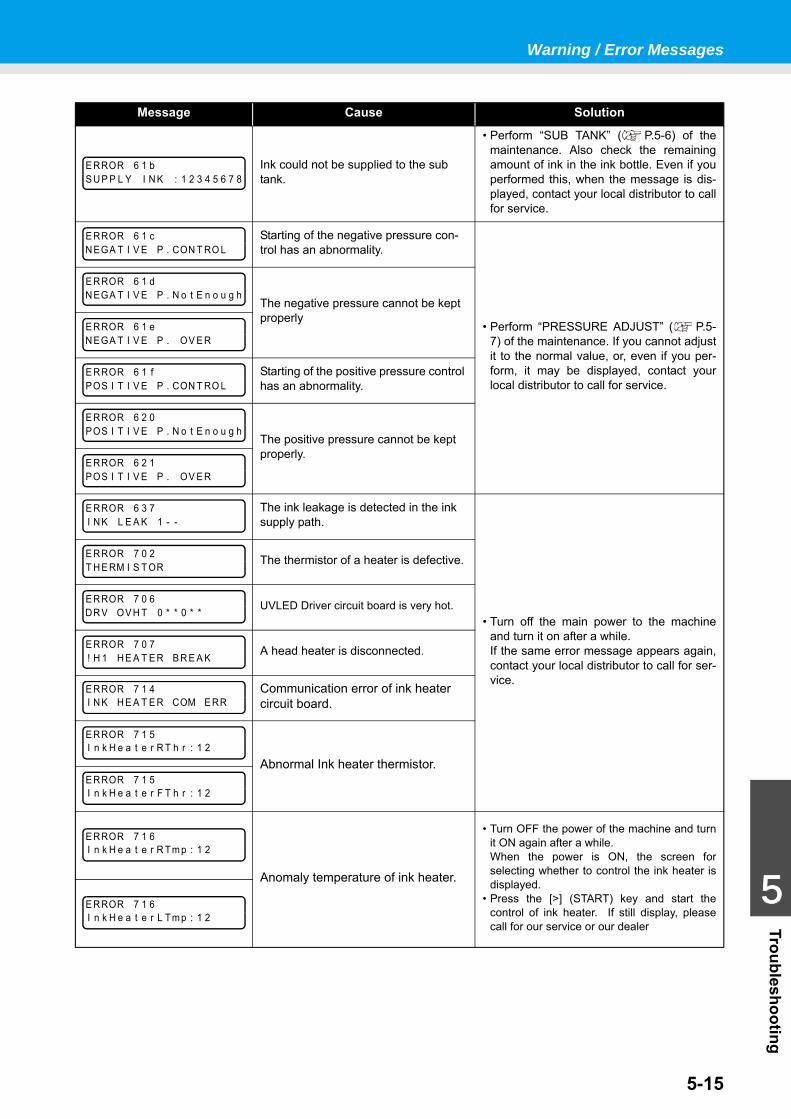
Warning / Error Messages
5-15
1
1
1
1
5
Troubleshooting
Message Cause Solution
Ink could not be supplied to the sub tank.
• Perform “SUB TANK” ( P.5-6) of themaintenance. Also check the remainingamount of ink in the ink bottle. Even if youperformed this, when the message is dis-played, contact your local distributor to callfor service.
Starting of the negative pressure con-trol has an abnormality.
• Perform “PRESSURE ADJUST” ( P.5-7) of the maintenance. If you cannot adjustit to the normal value, or, even if you per-form, it may be displayed, contact yourlocal distributor to call for service.
The negative pressure cannot be kept properly
Starting of the positive pressure control has an abnormality.
The positive pressure cannot be kept properly.
The ink leakage is detected in the ink supply path.
• Turn off the main power to the machineand turn it on after a while.If the same error message appears again,contact your local distributor to call for ser-vice.
The thermistor of a heater is defective.
UVLED Driver circuit board is very hot.
A head heater is disconnected.
Communication error of ink heater circuit board.
Abnormal Ink heater thermistor.
Anomaly temperature of ink heater.
• Turn OFF the power of the machine and turnit ON again after a while.When the power is ON, the screen forselecting whether to control the ink heater isdisplayed.
• Press the [>] (START) key and start thecontrol of ink heater. If still display, pleasecall for our service or our dealer
E RROR 6 1 bS U P P L Y I N K : 1 2 3 4 5 6 7 8
E RROR 6 1 cN EGA T I V E P . CON T RO L
E RROR 6 1 dN EGA T I V E P . N o t E n o u g h
E RROR 6 1 eN EGA T I V E P . OV E R
E RROR 6 1 fPOS I T I V E P . CON T RO L
E RROR 6 2 0POS I T I V E P . N o t E n o u g h
E RROR 6 2 1POS I T I V E P . OV E R
E RROR 6 3 7I N K L E A K 1 - -
E RROR 7 0 2T H E RM I S T OR
E RROR 7 0 6DR V OV H T 0 * * 0 * *
E RROR 7 0 7! H 1 H E A T E R B R E A K
E RROR 7 1 4I N K H E A T E R COM E RR
E RROR 7 1 5I n k H e a t e r R T h r : 1 2
E RROR 7 1 5I n k H e a t e r F T h r : 1 2
E RROR 7 1 6I n k H e a t e r R Tm p : 1 2
E RROR 7 1 6I n k H e a t e r L Tm p : 1 2
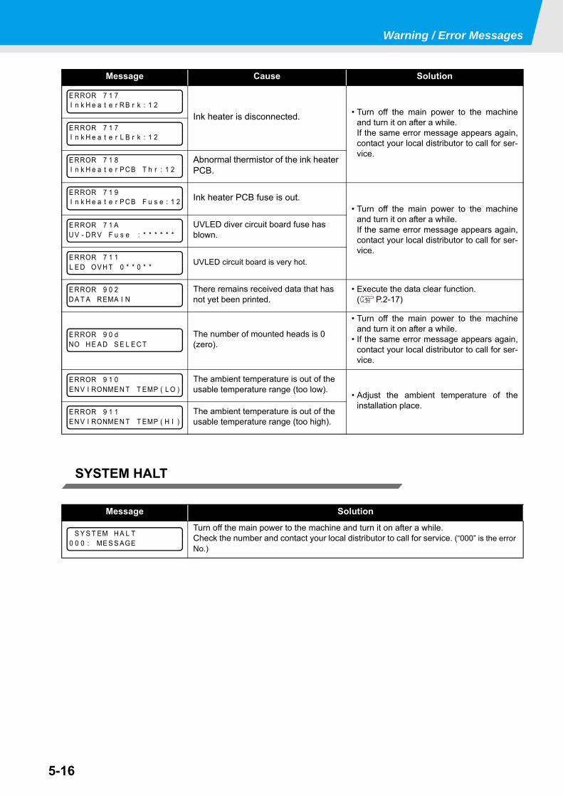
Warning / Error Messages
5-16
SYSTEM HALT
Message Cause Solution
Ink heater is disconnected. • Turn off the main power to the machineand turn it on after a while.If the same error message appears again,contact your local distributor to call for ser-vice.Abnormal thermistor of the ink heater
PCB.
Ink heater PCB fuse is out.• Turn off the main power to the machine
and turn it on after a while.If the same error message appears again,contact your local distributor to call for ser-vice.
UVLED diver circuit board fuse has blown.
UVLED circuit board is very hot.
There remains received data that has not yet been printed.
• Execute the data clear function. ( P.2-17)
The number of mounted heads is 0 (zero).
• Turn off the main power to the machineand turn it on after a while.
• If the same error message appears again,contact your local distributor to call for ser-vice.
The ambient temperature is out of the usable temperature range (too low). • Adjust the ambient temperature of the
installation place.The ambient temperature is out of the usable temperature range (too high).
Message Solution
Turn off the main power to the machine and turn it on after a while.Check the number and contact your local distributor to call for service. (“000” is the error No.)
E RROR 7 1 7I n k H e a t e r R B r k : 1 2
E RROR 7 1 7I n k H e a t e r L B r k : 1 2
E RROR 7 1 8I n k H e a t e r P C B T h r : 1 2
E RROR 7 1 9I n k H e a t e r P C B F u s e : 1 2
E RROR 7 1 AU V - DR V F u s e : * * * * * *
E RROR 7 1 1L E D OV H T 0 * * 0 * *
E RROR 9 0 2D A T A R EMA I N
E RROR 9 0 dNO H E A D S E L E C T
E RROR 9 1 0E N V I RONME N T T EMP ( L O )
E RROR 9 1 1E N V I RONME N T T EMP ( H I )
S Y S T EM H A L T0 0 0 : ME S S AGE

This chapter
contains the lists of the specifications and functions of this machine.
Specifications ..................................................................................6-2Machine specifications ....................................................................6-2Ink specifications .............................................................................6-3
Setting orders depending on ink type ..............................................6-4Setting orders of ink bottles .............................................................6-4
Sheet for inquiry ..............................................................................6-6Function Flowchart ..........................................................................6-8
Chapter 6Appendix
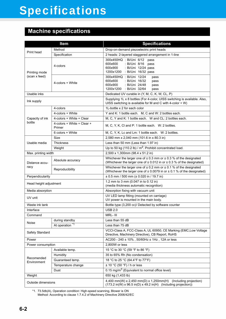
6-2
SpecificationsMachine specifications
Item Specifications
Print headMethod Drop-on-demand piezoelectric print headsSpecification 2 heads: 2-layered staggered arrangement in 1-line
Printing mode (scan x feed)
4-colors
300x450HQ : Bi/Uni 6/12 pass600x600 : Bi/Uni 8/16 pass600x900 : Bi/Uni 12/24 pass1200x1200 : Bi/Uni 16/32 pass
4-colors + White
300x450HQ : Bi/Uni 12/24 pass600x600 : Bi/Uni 16/32 pass600x900 : Bi/Uni 24/48 pass1200x1200 : Bi/Uni 32/64 pass
Usable inks Dedicated UV curable in (Y, M, C, K, W, CL, P)
Ink supply Supplying 1L x 8 bottles (For 4-color, UISS switching is available. Also, UISS switching is available for M and C with 4-color + W)
Capacity of ink bottle
4-colors 1L-bottle x 2 for each color4-colors + White Y and K: 1 bottle each. M, C and W: 2 bottles each.4-colors + White + Clear M, C, Y and K: 1 bottle each. W and CL: 2 bottles each.4-colors + White + Clear + Primer M, C, Y, K, Cl and P: 1 bottle each. W: 2 bottles.
6 colors + White M, C, Y, K, Lc and Lm: 1 bottle each. W: 2 bottles.
Usable mediaSize 2,580 mm x 2,040 mm (101.6 in x 80.3 in)Thickness Less than 50 mm (Less than 1.97 in)Weight Up to 50 kg (110.2 lb) / m2. Prohibit concentrated load.
Max. printing width 2,500 x 1,300mm (98.4 x 51.2 in)
Distance accu-racy
Absolute accuracy Whichever the larger one of ± 0.3 mm or ± 0.3 % of the designated(Whichever the larger one of ± 0.012 in or ± 0.3 % of the designated)
Reproducibility Whichever the larger one of ± 0.2 mm or ± 0.1 % of the designated(Whichever the larger one of ± 0.0079 in or ± 0.1 % of the designated)
Perpendicularity ± 0.5 mm / 500 mm (± 0.020 in / 19.7 in)
Head height adjustment 1.2 mm to 3 mm (0.047 in to 0.12 in)(media thickness automatic recognition)
Media absorption Absorption fixing with vacuum unit
UV unit UV LED lamp fitting (mounted on carriage)UV power is mounted in the main body.
Waste ink tank Bottle type (3,200 cc)/ Detected by software counterInterface USB 2.0Command MRL- III
Noiseduring standby Less than 55 dBAt operation *1
*1. 73.5db(A), Operation condition: High-speed scanning, Blower is ONMethod: According to clause 1.7.4.2 of Machinery Directive 2006/42/EC
Less than 75 dB
Safety Standard VCCI-Class A, FCC-Class A, UL 60950, CE Marking (EMC,Low Voltage Directive, Machinery Directive), CB Report, RoHS
Power AC200 - 240 ± 10% , 50/60Hz ± 1Hz , 12A or lessPower consumption 2,800W or less
Recomended Environment
Available temp. 15 °C to 30 °C (59 °F to 86 °F)Humidity 35 to 65% Rh (No condensation)Guaranteed temp. 18 °C to 25 °C (64.4°F to 77°F)Temperature change ± 10 °C (50 °F) / h or lessDust 0.15 mg/m3 (Equivalent to normal office level)
Weight 650 kg (1,433 lb)
Outside dimensions 4,400 mm(W) x 2,450 mm(D) x 1,250mm(H) (Including projection)(173.2 in(W) x 96.5 in(D) x 49.2 in(H) (Including projection))
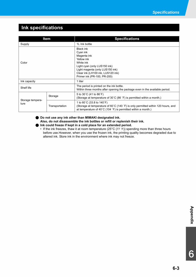
Specifications
6-3
Appendix
6
Ink specifications
Item SpecificationsSupply 1L Ink bottle
Color
Black inkCyan inkMagenta inkYellow inkWhite inkLight cyan (only LUS150 ink)Light magenta (only LUS150 ink)Clear ink (LH100 ink, LUS120 ink)Primer ink (PR-100, PR-200)
Ink capacity 1 liter
Shelf life The period is printed on the ink bottle.Within three months after opening the package even in the available period.
Storage tempera-ture
Storage 5 to 30˚C (41 to 86˚F)(Storage at temperature of 30˚C (86 ˚F) is permitted within a month.)
Transportation1 to 60˚C (33.8 to 140˚F)(Storage at temperature of 60˚C (140 ˚F) is only permitted within 120 hours, and at temperature of 40˚C (104 ˚F) is permitted within a month.)
Do not use any ink other than MIMAKI designated ink.Also, do not disassemble the ink bottles or refill or replenish their ink.
Ink could freeze if kept in a cold place for an extended period.• If the ink freezes, thaw it at room temperature (25°C (77 ˚F)) spending more than three hours
before use.However, when you use the frozen ink, the printing quality becomes degraded due to altered ink. Store ink in the environment where ink may not freeze.
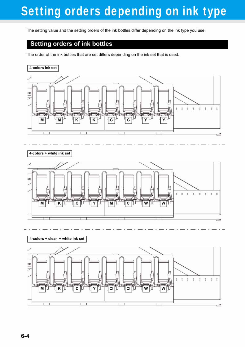
6-4
Setting orders depending on ink typeThe setting value and the setting orders of the ink bottles differ depending on the ink type you use.
Setting orders of ink bottlesThe order of the ink bottles that are set differs depending on the ink set that is used.
4-colors ink set
4-colors + white ink set
Y YK K CCMM
Y
Y
K CM W WCM
4-colors + clear + white ink set
YK CM W WCl Cl
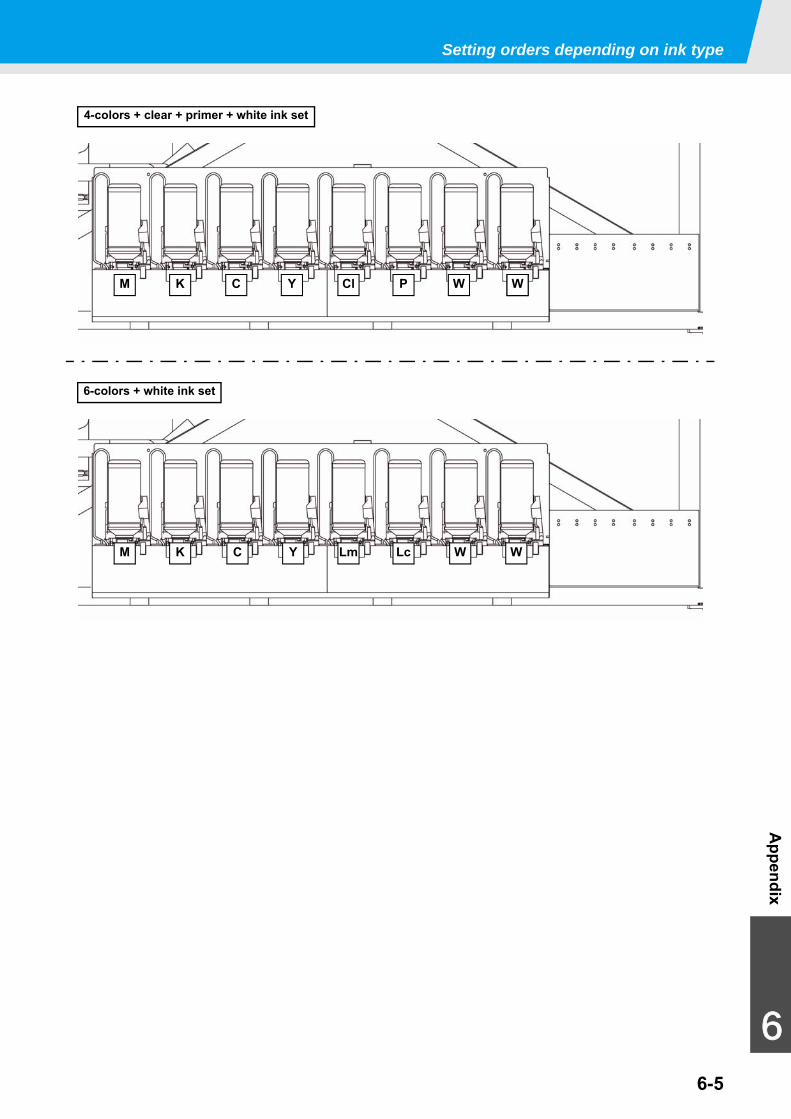
Setting orders depending on ink type
6-5
Appendix
6
6-colors + white ink set
M
YK CM W W
4-colors + clear + primer + white ink set
W YC Y PClK W
Lm Lc
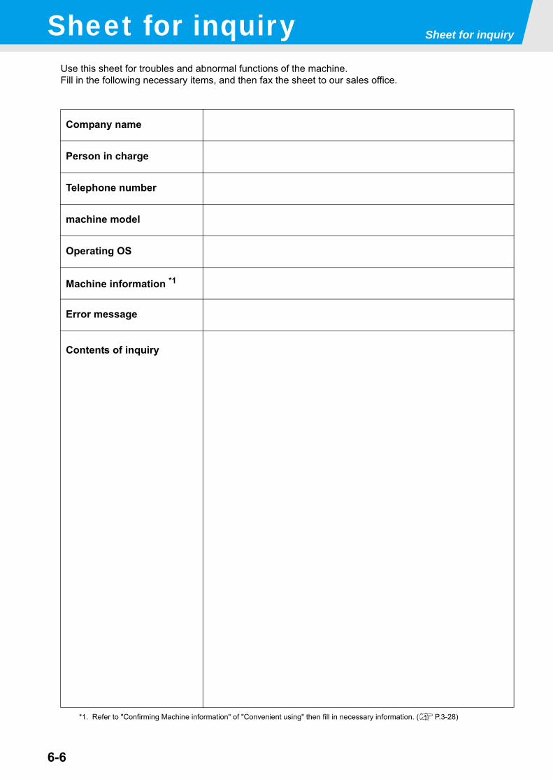
Sheet for inquiry
6-6
Sheet for inquiryUse this sheet for troubles and abnormal functions of the machine.Fill in the following necessary items, and then fax the sheet to our sales office.
Company name
Person in charge
Telephone number
machine model
Operating OS
Machine information *1
*1. Refer to "Confirming Machine information" of "Convenient using" then fill in necessary information. ( P.3-28)
Error message
Contents of inquiry

6-7
Appendix
6
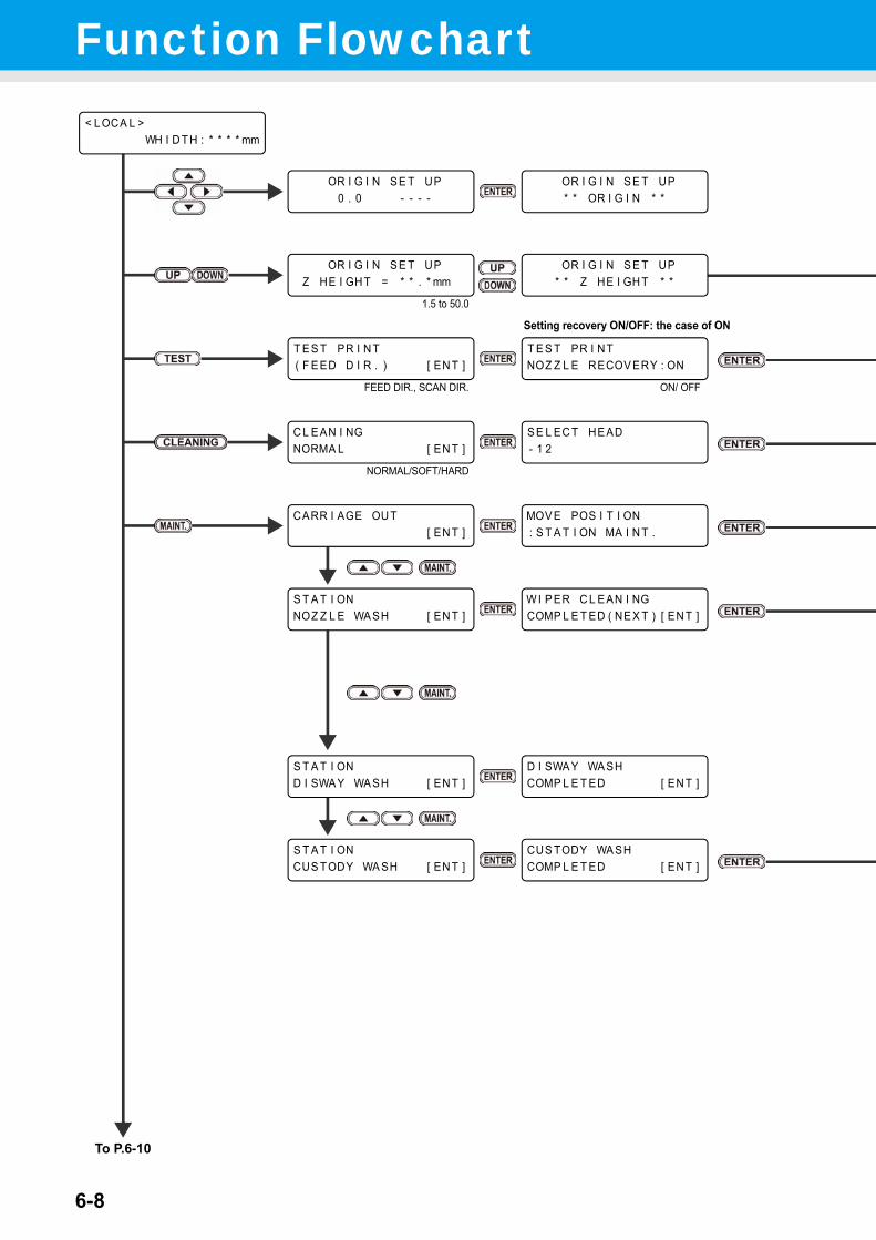
6-8
Function Flowchart
Setting recovery ON/OFF: the case of ON
OR I G I N S E T UP* * OR I G I N * *
OR I G I N S E T UP0 . 0 - - - -
< L OCA L >WH I D T H : * * * * mm
T E S T PR I N T( F E ED D I R . ) [ EN T ]
T E S T PR I NTNOZ Z L E RECOV ERY : ON
CARR I AGE OU T[ EN T ]
S T A T I ONNOZ Z L E WA SH [ EN T ]
W I P ER C L E AN I NGCOMP L E T ED ( NE X T ) [ ENT ]
OR I G I N S E T UPZ HE I GHT = * * . * mm
OR I G I N S E T UP* * Z HE I GH T * *
S T A T I OND I SWA Y WA SH [ EN T ]
D I SWA Y WA SHCOMP L E T ED [ ENT ]
1.5 to 50.0
C L E AN I NGNORMA L [ EN T ]
S E L EC T HE AD- 1 2
NORMAL/SOFT/HARD
MOV E POS I T I ON: S T A T I ON MA I N T .
S T A T I ONCUS TODY WA SH [ EN T ]
CUS TODY WA SHCOMP L E T ED [ ENT ]
To P.6-10
FEED DIR., SCAN DIR. ON/ OFF
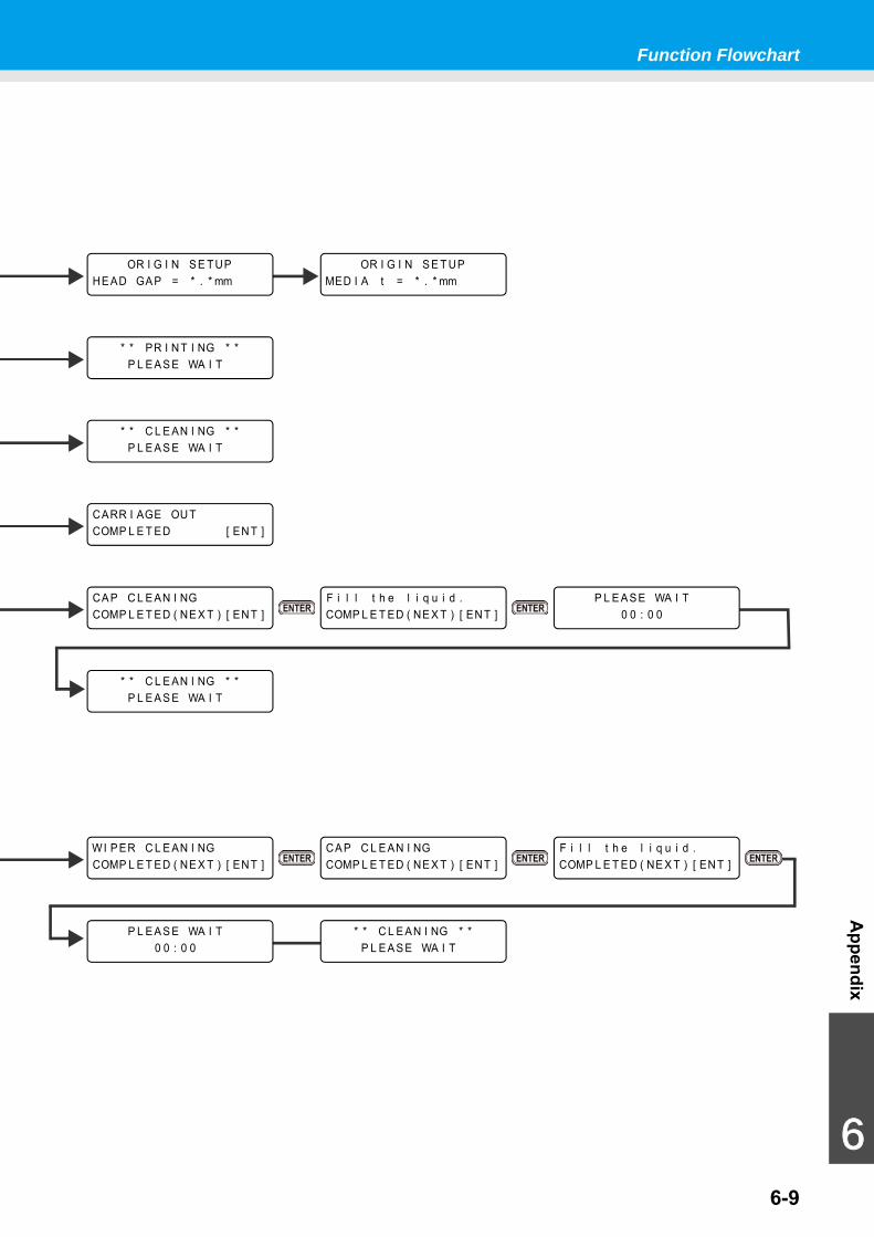
Function Flowchart
6-9
Appendix
6
* * C L E AN I NG * *P L E A S E WA I T
CARR I AGE OU TCOMP L E T ED [ EN T ]
CA P C L E AN I NGCOMP L E T ED ( NE X T ) [ EN T ]
WI P ER C L E AN I NGCOMP L E T ED ( NE X T ) [ EN T ]
F i l l t h e l i q u i d .COMP L E T ED ( NE X T ) [ EN T ]
F i l l t h e l i q u i d .COMP L E T ED ( NE X T ) [ EN T ]
CA P C L E AN I NGCOMP L E T ED ( NE X T ) [ EN T ]
P L E A S E WA I T0 0 : 0 0
P L E A S E WA I T0 0 : 0 0
* * C L E AN I NG * *P L E A S E WA I T
OR I G I N S E T UPHE AD GA P = * . * mm
OR I G I N S E T UPMED I A t = * . * mm
* * C L E AN I NG * *P L E A S E WA I T
* * PR I N T I NG * *P L E A S E WA I T
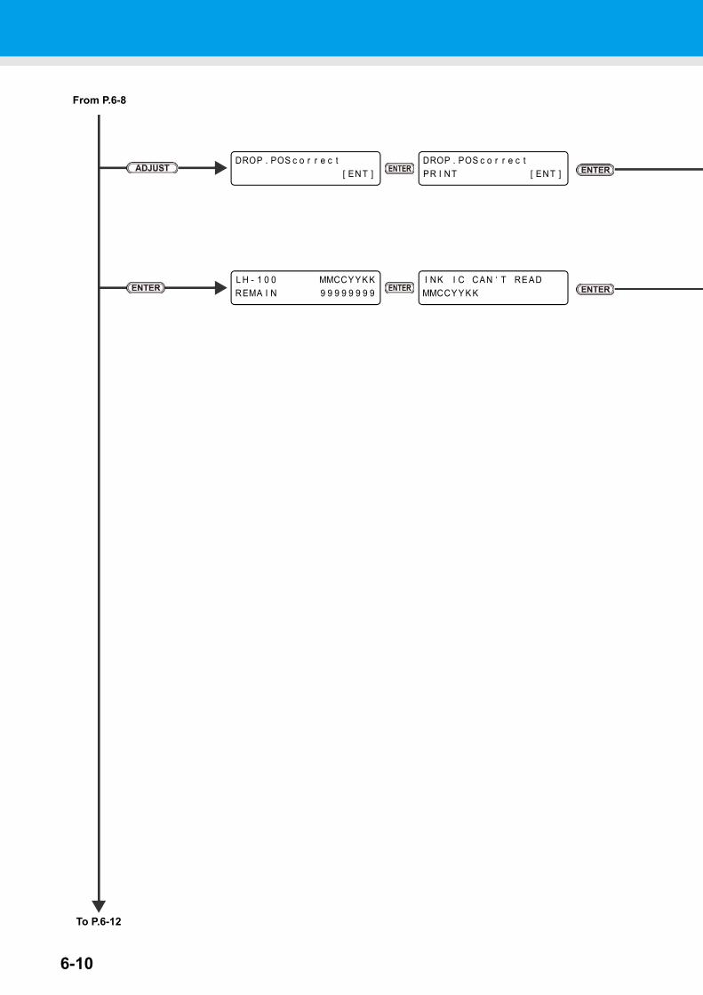
6-10
DROP . POS c o r r e c t[ EN T ]
DROP . POS c o r r e c tPR I NT [ ENT ]
L H - 1 0 0 MMCCY Y K KREMA I N 9 9 9 9 9 9 9 9
I NK I C CAN ‘ T RE ADMMCCY Y K K
To P.6-12
From P.6-8
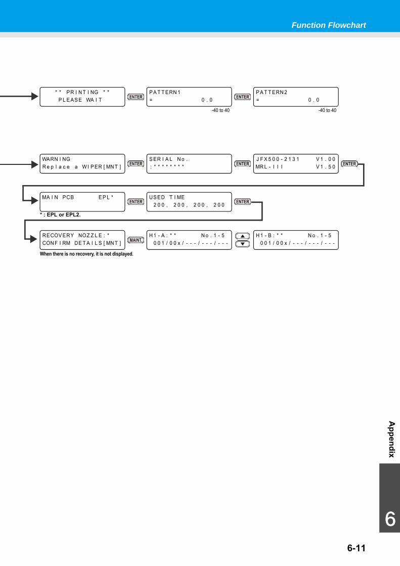
Function Flowchart
6-11
Appendix
6
P A T T ERN 1= 0 . 0
* * PR I N T I NG * *P L E A S E WA I T
P A T T ERN 2= 0 . 0
S ER I A L N o .: * * * * * * * *
WARN I NGR e p l a c e a WI P ER [ MN T ]
J F X 5 0 0 - 2 1 3 1 V 1 . 0 0MR L - I I I V 1 . 5 0
MA I N PCB E P L *
RECOV ERY NOZ Z L E : *CON F I RM DE T A I L S [ MN T ]
When there is no recovery, it is not displayed.
H 1 - A : * * N o . 1 - 50 0 1 / 0 0 x / - - - / - - - / - - -
H 1 - B : * * N o . 1 - 50 0 1 / 0 0 x / - - - / - - - / - - -
-40 to 40 -40 to 40
US ED T I ME2 0 0 , 2 0 0 , 2 0 0 , 2 0 0
* : EPL or EPL2.
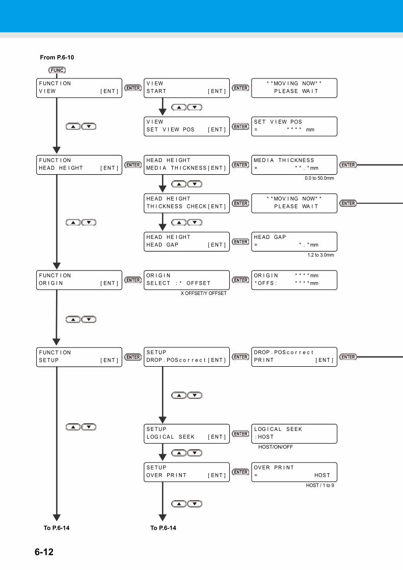
6-12
HE AD GA P= * . * mm
HE AD HE I GH THE AD GA P [ EN T ]
* * MOV I NG NOW* *P L E A S E WA I T
To P.6-14
From P.6-10
F UNC T I ONV I EW [ EN T ]
F UNC T I ONHE AD HE I GH T [ EN T ]
V I EWS T AR T [ EN T ]
V I EWS E T V I EW POS [ EN T ]
* * MOV I NG NOW* *P L E A S E WA I T
S E T V I EW POS= * * * * mm
HE AD HE I GH TMED I A T H I CKNE S S [ EN T ]
HE AD HE I GH TT H I CKNE S S CHECK [ EN T ]
MED I A T H I CKNE S S= * * . * mm
0.0 to 50.0mm
1.2 to 3.0mm
F UNC T I ONOR I G I N [ EN T ]
OR I G I NS E L EC T : * OF F S E T
OR I G I N * * * * mm* OF F S : * * * * mm
F UNC T I ONS E T UP [ EN T ]
S E T UPDROP . POS c o r r e c t [ EN T ]
DROP . POS c o r r e c tPR I N T [ EN T ]
S E T UPL OG I CA L S E E K [ EN T ]
L OG I CA L S E E K: HOS T
S E T UPOV ER PR I N T [ EN T ]
OV ER PR I N T= HOS T
HOST/ON/OFF
HOST / 1 to 9
To P.6-14
X OFFSET/Y OFFSET
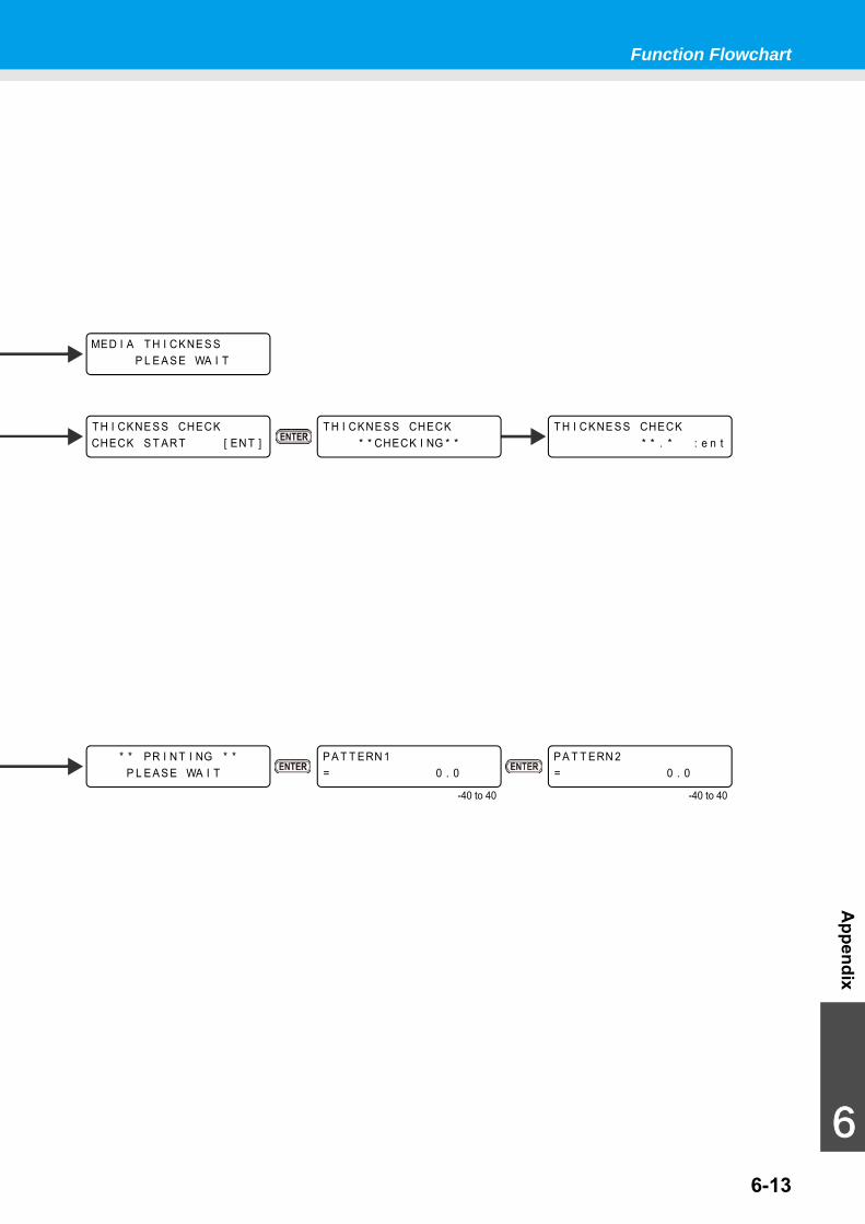
Function Flowchart
6-13
Appendix
6
MED I A T H I CKNE S SP L E A S E WA I T
T H I CKNE S S CHECKCHECK S T AR T [ EN T ]
T H I CKNE S S CHECK* * . * : e n t
T H I CKNE S S CHECK* * CHECK I NG * *
* * PR I N T I NG * *P L E A S E WA I T
P A T T ERN 2= 0 . 0
P A T T ERN 1= 0 . 0
-40 to 40 -40 to 40
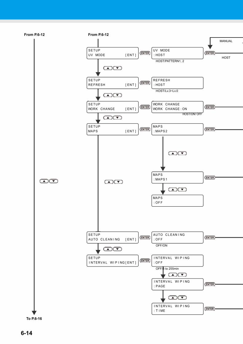
6-14
I N T ERV A L WI P I NG: T I ME
S E T UPRE F RE SH [ EN T ]
RE F RE SH: HOS T
HOST/Lv.3~Lv.0
S E T UPAU TO C L E AN I NG [ EN T ]
To P.6-16
From P.6-12
S E T UPI N T ERV A L WI P I NG [ EN T ]
From P.6-12
S E T UPUV MODE [ EN T ]
UV MODE: HOS T
HOST/PATTERN1, 2
AUTO C L E AN I NG: OF F
OFF/ON
I NT ERV A L WI P I NG: OF F
OFF/3 to 255min
S E T UPMA P S [ EN T ]
MA P S: OF F
MA P S: MA P S 1
MA P S: MA P S 2
HOST
MANUAL
S E T UPWORK CHANGE [ EN T ]
WORK CHANGEWORK CHANGE : ON
HOST/ON/ OFF
I N T ERV A L WI P I NG: P AGE
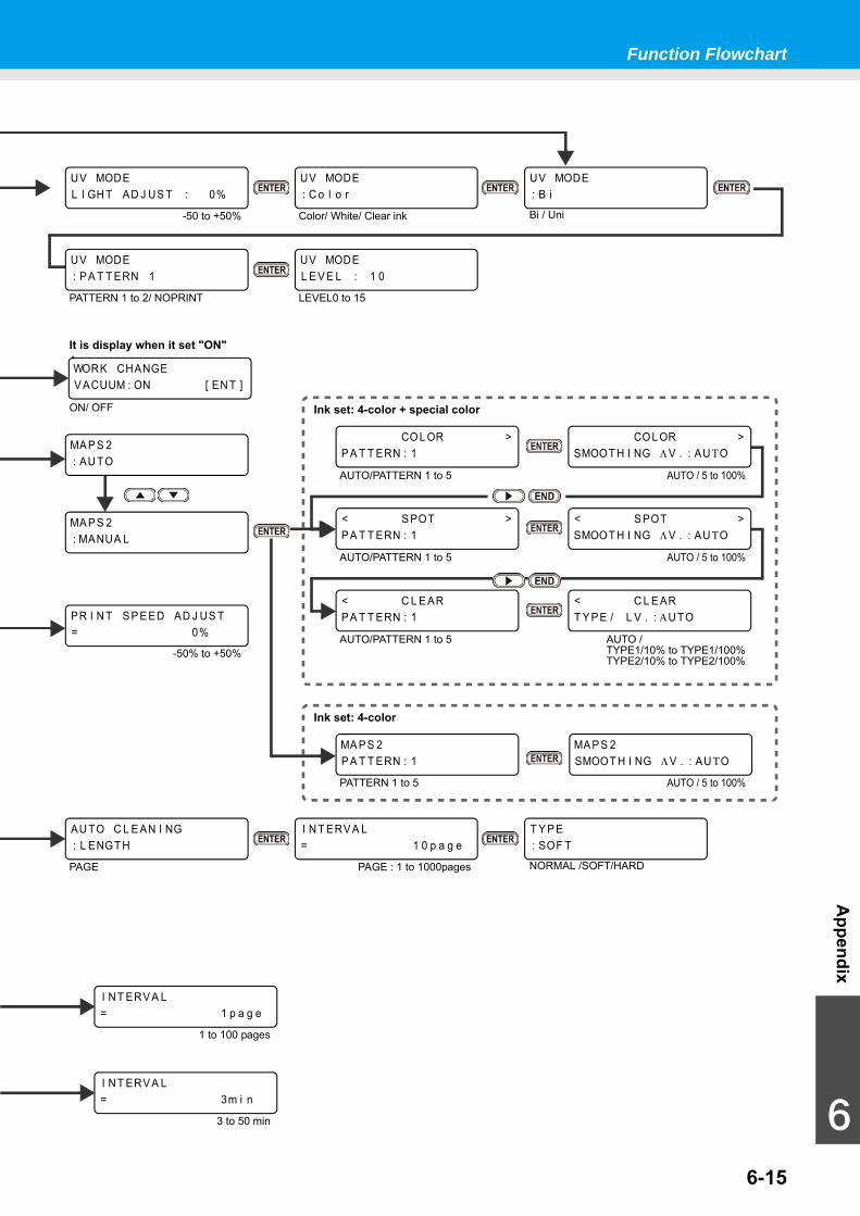
Function Flowchart
6-15
Appendix
6
AU TO C L E AN I NG: L ENGT H
PAGE
I N T ERV A L= 1 0 p a g e
PAGE : 1 to 1000pages
T Y P E: SOF T
NORMAL /SOFT/HARD
UV MODEL I GH T AD J US T : 0%
-50 to +50%
CO L OR >P A T T ERN : 1
CO L OR >SMOOT H I NG Λ V . : AU ΤO
Ink set: 4-color + special color
MA P S 2P A T T ERN : 1
Ink set: 4-color
PR I N T S P E ED AD J US T= 0%
-50% to +50%
MA P S 2: AU TO
MA P S 2: MANUA L
MA P S 2SMOOT H I NG Λ V . : AU ΤO
PATTERN 1 to 5 AUTO / 5 to 100%
AUTO/PATTERN 1 to 5 AUTO / 5 to 100%
< S POT >P A T T ERN : 1
< S POT >SMOOT H I NG Λ V . : AU ΤO
AUTO/PATTERN 1 to 5 AUTO / 5 to 100%
< C L E ARP A T T ERN : 1
< C L E ART Y P E / L V . : ΑU TO
AUTO/PATTERN 1 to 5 AUTO /TYPE1/10% to TYPE1/100%TYPE2/10% to TYPE2/100%
UV MODE: C o l o r
Color/ White/ Clear ink
UV MODE: B i
Bi / Uni
UV MODE: P A T T ERN 1
PATTERN 1 to 2/ NOPRINT
UV MODEL E V E L : 1 0
LEVEL0 to 15
WORK CHANGEV ACUUM : ON [ EN T ]
ON/ OFF
It is display when it set "ON"
I NT ERV A L= 1 p a g e
1 to 100 pages
I NT ERV A L= 3m i n
3 to 50 min
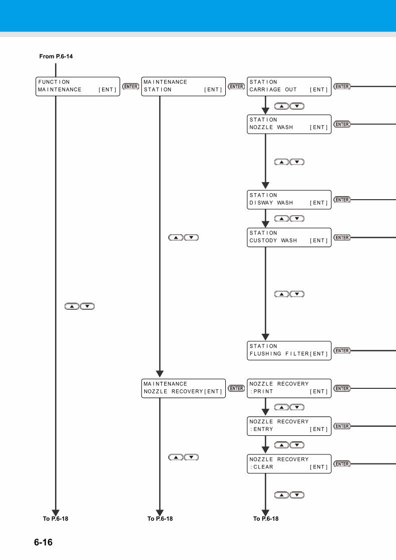
6-16
F UNC T I ONMA I N T ENANCE [ EN T ]
MA I N T ENANCES T A T I ON [ EN T ]
S T A T I ONCARR I AGE OU T [ EN T ]
NOZ Z L E RECOV ERY: PR I N T [ EN T ]
MA I N T ENANCENOZ Z L E RECOV ERY [ EN T ]
NOZ Z L E RECOV ERY: EN T RY [ EN T ]
To P.6-18
From P.6-14
S T A T I ONF L USH I NG F I L T ER [ EN T ]
To P.6-18
S T A T I ONNOZ Z L E WA SH [ EN T ]
S T A T I OND I SWA Y WA SH [ EN T ]
S T A T I ONCUS TODY WA SH [ EN T ]
NOZ Z L E RECOV ERY: C L E AR [ EN T ]
To P.6-18
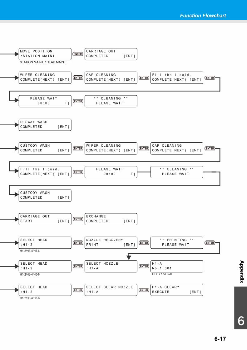
Function Flowchart
6-17
Appendix
6
MOV E POS I T I ON: S T A T I ON MA I NT .
STATION MAINT. / HEAD MAINT.
F i l l t h e l i q u i d .COMP L E T E ( NE X T ) [ EN T ]
CUS TODY WA SHCOMP L E T ED [ EN T ]
D I SWA Y WA SHCOMP L E T ED [ EN T ]
* * C L E AN I NG * *P L E A S E WA I T
P L E A S E WA I T0 0 : 0 0 T ]
* * C L E AN I NG * *P L E A S E WA I T
P L E A S E WA I T0 0 : 0 0 T ]
CARR I AGE OU TCOMP L E T ED [ EN T ]
WI P ER C L E AN I NGCOMP L E T E ( NE X T ) [ EN T ]
CA P C L E AN I NGCOMP L E T E ( NE X T ) [ EN T ]
S E L EC T HE AD: H 1 - 2
S E L EC T HE AD: H 1 - 2
S E L EC T HE AD: H 1 - 2
H1-2/H3-4/H5-6
H1-2/H3-4/H5-6
H1-2/H3-4/H5-6
* * PR I NT I NG * *P L E A S E WA I T
NOZ Z L E RECOV ERYPR I N T [ EN T ]
H 1 - AN o . 1 : 0 0 1
S E L EC T NOZ Z L E: H 1 - A
OFF / 1 to 320
H 1 - A C L E AR ?E X ECU T E [ EN T ]
S E L EC T C L E AR NOZ Z L E: H 1 - A
CARR I AGE OU TS T AR T [ EN T ]
E XCHANGECOMP L E T ED [ EN T ]
F i l l t h e l i q u i d .COMP L E T E ( NE X T ) [ EN T ]
W I P ER C L E AN I NGCOMP L E T E ( NE X T ) [ EN T ]
CA P C L E AN I NGCOMP L E T E ( NE X T ) [ EN T ]
CUS TODY WA SHCOMP L E T ED [ EN T ]
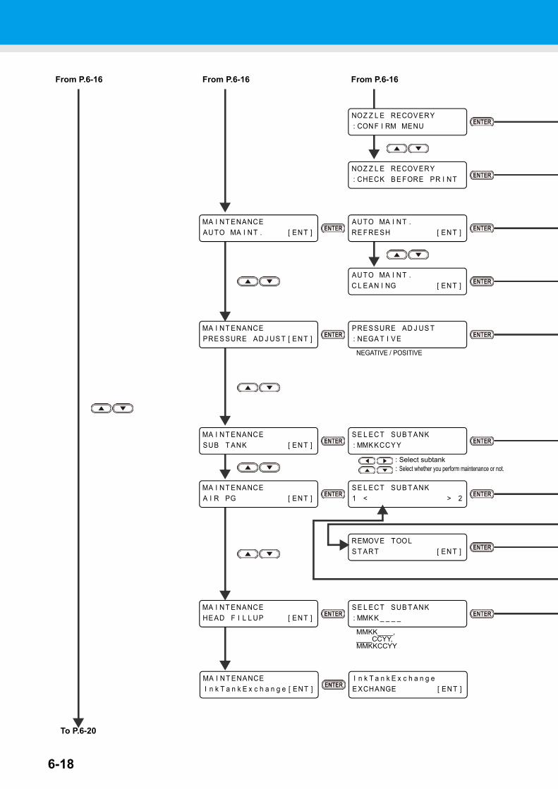
6-18
S E L EC T SUB T ANK: MMK KCCY Y
MA I N T ENANCESUB T ANK [ EN T ]
To P.6-20
MA I N T ENANCEAU TO MA I N T . [ EN T ]
MA I N T ENANCEPRE S SURE AD J US T [ EN T ]
PRE S SURE AD J US T: NEGA T I V E
From P.6-16
AUTO MA I N T .RE F RE SH [ EN T ]
AU TO MA I N T .C L E AN I NG [ EN T ]
NEGATIVE / POSITIVE
: Select subtank: Select whether you perform maintenance or not.
From P.6-16 From P.6-16
NOZ Z L E RECOV ERY: CON F I RM MENU
NOZ Z L E RECOV ERY: CHECK B E FORE PR I N T
MA I N T ENANCEHE AD F I L L UP [ EN T ]
S E L EC T SUB T ANK: MMK K _ _ _ _
MA I N T ENANCEA I R PG [ EN T ]
S E L EC T SUB T ANK1 < > 2
REMOV E TOOLS T AR T [ EN T ]
MMKK____,____CCYY,MMKKCCYY
I n k T a n k E x c h a n g eE XCHANGE [ EN T ]
MA I NT ENANCEI n k T a n k E x c h a n g e [ ENT ]
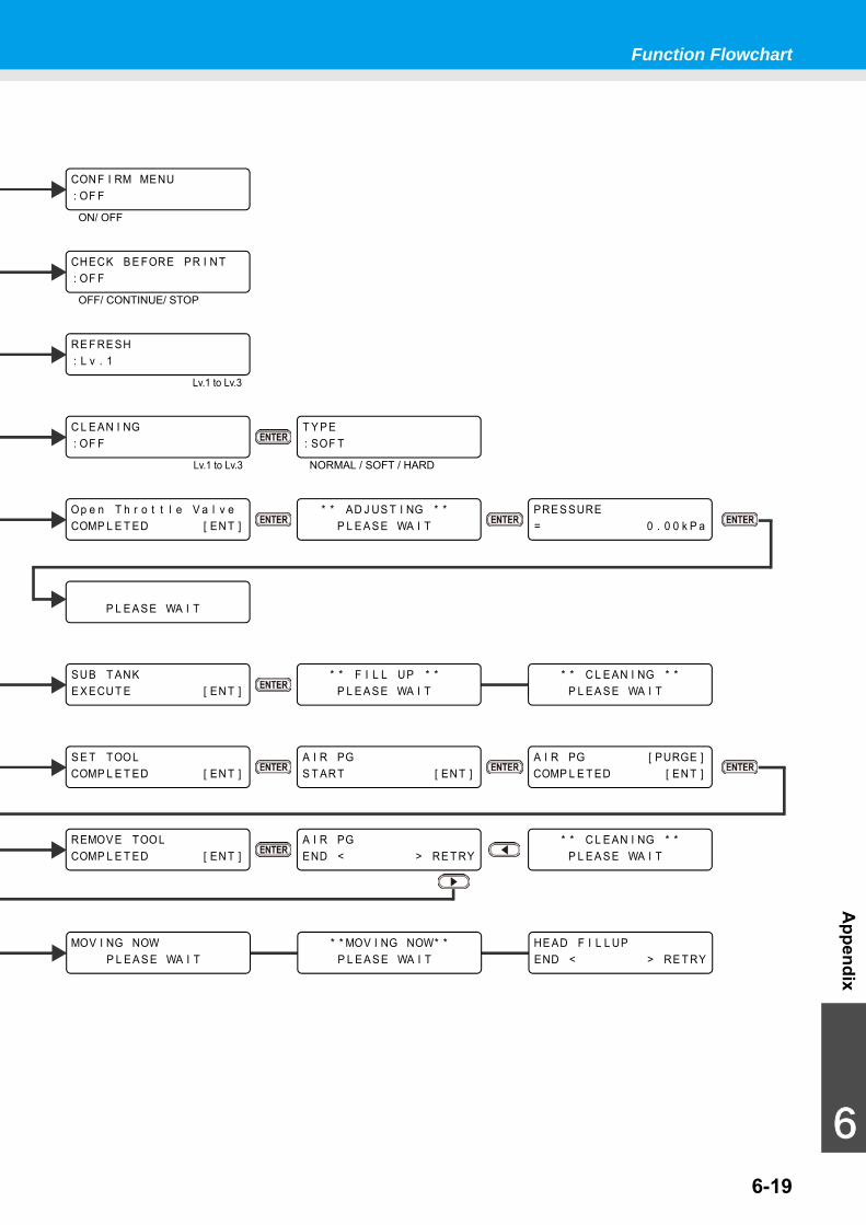
Function Flowchart
6-19
Appendix
6
HE AD F I L L UPEND < > RE T RY
MOV I NG NOWP L E A S E WA I T
* * MOV I NG NOW* *P L E A S E WA I T
Op e n T h r o t t l e V a l v eCOMP L E T ED [ EN T ]
RE F RE SH: L v . 1
Lv.1 to Lv.3
Lv.1 to Lv.3
C L E AN I NG: OF F
T Y P E: SOF T
NORMAL / SOFT / HARD
* * AD J US T I NG * *P L E A S E WA I T
PRE S SURE= 0 . 0 0 k P a
P L E A S E WA I T
* * C L E AN I NG * *P L E A S E WA I T
SUB T ANKE X ECU T E [ EN T ]
* * F I L L UP * *P L E A S E WA I T
CON F I RM MENU: OF F
ON/ OFF
OFF/ CONTINUE/ STOP
CHECK B E FORE PR I N T: OF F
A I R PG [ PURGE ]COMP L E T ED [ EN T ]
S E T TOOLCOMP L E T ED [ EN T ]
A I R PGS T AR T [ EN T ]
A I R PGEND < > RE T RY
* * C L E AN I NG * *P L E A S E WA I T
REMOV E TOOLCOMP L E T ED [ EN T ]
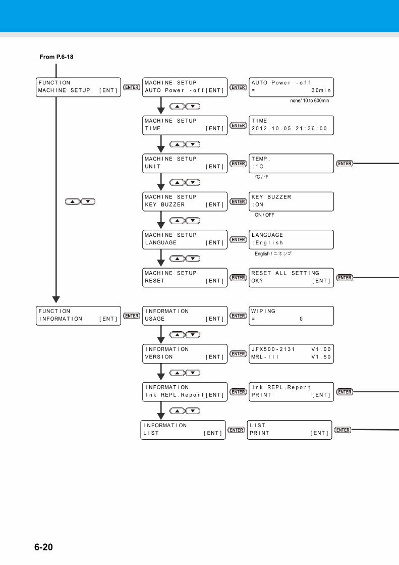
6-20
I N FORMA T I ONL I S T [ EN T ]
L I S TPR I N T [ EN T ]
MACH I NE S E T UPK E Y BUZ Z ER [ EN T ]
K E Y BU Z Z ER: ON
L ANGUAGE: E n g l i s h
MACH I NE S E T UPL ANGUAGE [ EN T ]
F UNC T I ONI N FORMA T I ON [ EN T ]
I N FORMA T I ONUS AGE [ EN T ]
WI P I NG= 0
I N FORMA T I ONV ERS I ON [ EN T ]
J F X 5 0 0 - 2 1 3 1 V 1 . 0 0MR L - I I I V 1 . 5 0
I N FORMA T I ONI n k RE P L . R e p o r t [ EN T ]
I n k RE P L . R e p o r tPR I N T [ EN T ]
MACH I NE S E T UPRE S E T [ EN T ]
RE S E T A L L S E T T I NGOK ? [ EN T ]
F UNC T I ONMACH I NE S E T UP [ EN T ]
MACH I NE S E T UPAU TO P o w e r - o f f [ EN T ]
AUTO P o w e r - o f f= 3 0m i n
MACH I NE S E T UPT I ME [ EN T ]
T I ME2 0 1 2 . 1 0 . 0 5 2 1 : 3 6 : 0 0
T EMP .: ° C
MACH I NE S E T UPUN I T [ EN T ]
From P.6-18
ON / OFF
English / ニホンゴ
none/ 10 to 600min
°C / °F
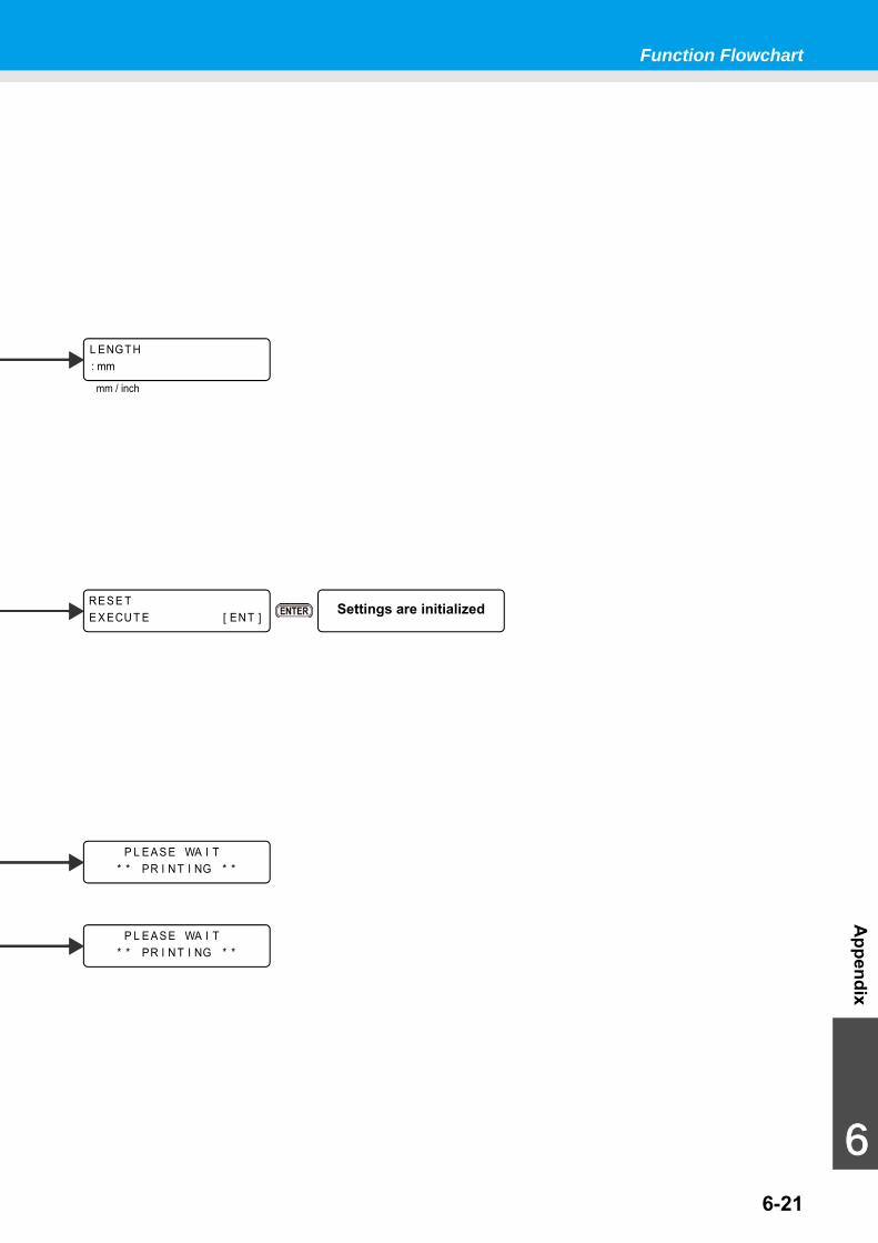
Function Flowchart
6-21
Appendix
6
RE S E TE X ECU T E [ EN T ] Settings are initialized
P L E A S E WA I T* * PR I N T I NG * *
P L E A S E WA I T* * PR I N T I NG * *
L ENGT H: mm
mm / inch


JFX200-2513 Operation Manual
March, 2017
MIMAKI ENGINEERING CO.,LTD.2182-3 Shigeno-otsu, Tomi-shi, Nagano 389-0512 JAPAN
D202563-17-31032017

© MIMAKI ENGINEERING CO., LTD.2016MM
FW : 2.30