Embed Size (px)
Citation preview
Operating Instructions
for
Electromagnetic Flowmeter
Model: MIM
MIM-
page 2 MIM 01/0419
We don’t accept warranty and liability claims neither upon this publication nor in case of improper treatment of the described products. The document may contain technical inaccuracies and typographical errors. The content will be revised on a regular basis. These changes will be implemented in later versions. The described products can be improved and changed at any time without prior notice. © Copyright All rights reserved.
1. Contents
1. Contents .......................................................................................................... 2 2. Note ................................................................................................................. 4
2.1 Overview of the device functionality ...................................................... 4 3. Instrument Inspection ...................................................................................... 5 4. Regulation Use ............................................................................................... 5 5. Environment .................................................................................................... 5 6. Operating principle .......................................................................................... 6
6.1 General .................................................................................................. 6 6.2 Minimum electrical conductivity / Gas bubbles ..................................... 6 6.3 Deposits ................................................................................................. 6 6.4 Measuring electrodes ............................................................................ 6
7. Mechanical connection ................................................................................... 7 7.1 Check operating conditions ................................................................... 7 7.2 Installation ............................................................................................. 7
8. Electrical Connection ...................................................................................... 9 8.1 General .................................................................................................. 9 8.2 Pin assignment .................................................................................... 10
9. Operation and menu structure ...................................................................... 11 9.1 General ................................................................................................ 11 9.2 Measuring mode .................................................................................. 12 9.3 Menu Mode .......................................................................................... 15
10. Device configuration ..................................................................................... 16 10.1 Sequence of device parameterization ................................................. 16 10.2 Language ............................................................................................. 16 10.3 Display ................................................................................................. 17 10.4 Measurement ....................................................................................... 19 10.5 Dosing function .................................................................................... 23 10.6 Outputs ................................................................................................ 23 10.7 User service ......................................................................................... 35 10.8 Service / Factory service ..................................................................... 36 10.9 Info ....................................................................................................... 36 10.10 Device default settings ........................................................................ 37
11. Status ............................................................................................................ 38 12. Dosing function ............................................................................................. 39 13. IO-Link function ............................................................................................. 44
13.1 Specification ........................................................................................ 44 14. Technical Information .................................................................................... 45
MIM-
MIM 01/0419 page 3
15. Order Codes ................................................................................................. 46 16. Dimensions ................................................................................................... 47 17. Appendix ....................................................................................................... 48
17.1 IO-Link process data structure ............................................................ 48 17.2 IO-Link diagnosis information .............................................................. 49 17.3 IO-Link system command table ........................................................... 50 17.4 IO Link ISDU parameter table ............................................................. 51
18. Manufacturer’s declaration ........................................................................... 59 19. EU Declaration of Conformance ................................................................... 60
Manufactured and sold by:
KOBOLD Instruments Inc 1801 Parkway View Drive Pittsburgh PA 15205-1422
Tel.: 412-788-2830 Fax: 412-788-4890
E-Mail: [email protected] Internet: www.koboldusa.com

MIM-
page 4 MIM 01/0419
2. Note
Please read these operating instructions before unpacking and putting the unit into operation. Follow the instructions precisely as described herein. The devices are only to be used, maintained and serviced by persons familiar with these operating instructions and in accordance with local regulations applying to Health & Safety and prevention of accidents. When used in machines, the measuring unit should be used only when the machines fulfil the EC-machine guidelines. as per PED 2014/68/EU In acc. with Article 4 Paragraph (3), "Sound Engineering Practice", of the PED 2014/68/EU no CE mark. Diagram 8, Pipe, Group 1 dangerous fluids
2.1 Overview of the device functionality
Depending on the installed device firmware, the MIM device may have different functionalities. The functional extensions are shown in the following table.
Function extension Available from firmware version Dosing function REV180118 Menu languages Simulation function User function keys Analogue output 2-10 VDC
Analogue output behavior acc. to NAMUR NE43
REV180514
IO-Link Control input
REV181121
The installed software version is displayed after starting the device below the manufacturer logo in the form REVxxxxxx for approx. 2 sec.
MIM-
MIM 01/0419 page 5
3. Instrument Inspection
Instruments are inspected before shipping and sent out in perfect condition. Should damage to a device be visible, we recommend a thorough inspection of the delivery packaging. In case of damage, please inform your parcel service / forwarding agent immediately, since they are responsible for damages during transit. Scope of delivery: The standard delivery includes: Electromagnetic Flowmeter model: MIM Operating Instructions
4. Regulation Use
The MIM flowmeter has been specially developed for the measurement, display and transmission of both, flow rates and temperature of conductive liquids. The instrument has a graphic TFT display, rotatable in 90 ° steps and can display flow rate, temperature, daily volume counter (resettable) and total volume counter in the units of measurement selected by the operator. A clear menu guides the user through the parameterization of the device, which largely eliminates the need to look into the operating instructions. Any use of the magnetic flowmeter, model: MIM, which exceeds the manufacturer’s specification, may invalidate its warranty. Therefore, any resulting damage is not the responsibility of the manufacturer. The user assumes all risk for such usage.
5. Environment
The MIM device with stainless steel housing and stainless steel electrodes is weatherproof and conforms to protection class IP67. The meter is designed for harsh indoor or outdoor environments and complies with Directive 2014/30/EU (Electromagnetic Compatibility).
MIM-
page 6 MIM 01/0419
6. Operating principle
6.1 General
The new KOBOLD MIM Flowmeter is designed to measure and monitor small and medium flows of conductive fluids in piping. The device works on the magnetic-inductive measuring principle. According to Faraday's law of induction, a voltage is induced in a conductor moving in a magnetic field. The electrically conductive measuring medium corresponds to the moving conductor in the process. The voltage induced by the measuring medium is proportional to the flow rate and thus a measure of the volume throughput. Prerequisite is a minimum electrical conductivity of the flowing medium. The induced voltage is fed to a measuring amplifier via two electrodes, which are in conductive contact with the medium. The volume flow is calculated via the defined pipe diameter. The measurement is independent of the medium and its physical properties such as density, viscosity and temperature. The device can be configured via the display. There are two outputs available, which can each be configured as alarm, frequency, pulse, voltage, and current outputs. The device also provides a dosing function. The dosing function can be activated in measuring mode via the four buttons. The dosing function controls simple filling tasks and also measures flow rate and partial amount.
6.2 Minimum electrical conductivity / Gas bubbles
For the correct function of the instrument, it is necessary that the flow channel is always completely filled with medium. From a minimum electrical conductivity of 20 μS / cm, the MIM operates within the specified error limits. The conductivity of the medium is constantly monitored by the device electronics. If the electronics detects that the minimum conductivity has fallen below min. value, this is signaled by displaying the error message 'Empty pipe' and the flow rate reading is set to '0'. Air bubbles in the flowing medium or media with varying conductivity in the range of the minimum conductivity can disturb the measuring function and reduce the measuring accuracy of the MIM. Gases contained in the liquid are also measured as a flow volume and lead to measurement errors. If necessary, install appropriate vents in the flow of the unit.
6.3 Deposits
Minor deposits on the measuring tube generally do not affect the measuring accuracy unless their conductivity deviates significantly from the liquid. For liquids that have a tendency to deposit, periodically inspect the meter tube and, if necessary, clean it.
6.4 Measuring electrodes
The MIM uses electrodes with galvanic tapping. They are in direct contact with the medium. The standard electrodes are made of stainless steel 1.4404 (316 SS).
MIM-
MIM 01/0419 page 7
7. Mechanical connection
7.1 Check operating conditions
flow rate max. operating pressure max. operating temperature In general, MIM is subjected to the same loads as the piping into which it is installed. The MIM should therefore be kept away from extreme loads, such as pressure surges with strong, dynamic pipe movements, vibrations in the proximity of centrifugal pumps, high temperature media, flooding etc.
7.2 Installation
Remove all packing materials and transport retainers and ensure that no such materials remain in the device.
It can be installed in vertical, horizontal or rising pipes. Flow in direction of the arrow.
Avoid pressure and tensile load. Mechanically secure the inlet and outlet pipe at a distance of 50 mm from the
connections. Avoid valves or large reduction on the inlet section (this increases the
inaccuracy of measurements). Check the leak tightness of the connections.
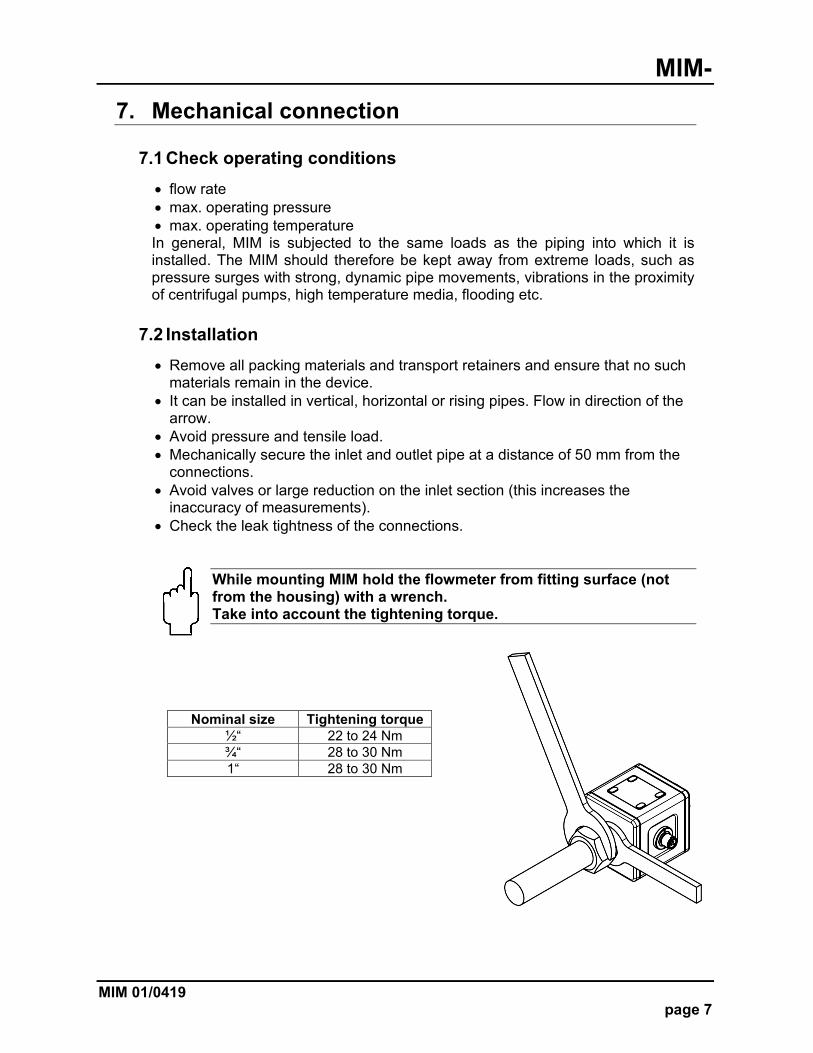
While mounting MIM hold the flowmeter from fitting surface (not from the housing) with a wrench. Take into account the tightening torque.
Nominal size Tightening torque ½“ 22 to 24 Nm ¾“ 28 to 30 Nm 1“ 28 to 30 Nm
MIM-
page 8 MIM 01/0419
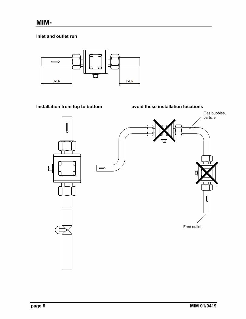
Inlet and outlet run
Installation from top to bottom avoid these installation locations
Gas bubbles, particle
Free outlet
MIM-
MIM 01/0419 page 9
8. Electrical Connection
8.1 General
Attention! Make sure that the voltage values of your system correspond with the voltage values of the measuring unit.
Make sure that the supply wires are de-energised. Connect the supply voltage and the output signal to the plug PIN’s as stated
below. We recommend using wires with cross sectional area of minimum 0.25 mm²
(22 AWG).
Attention! The measuring electrodes are galvanically connected with the reference potential of the supply voltage and the signal output.
MIM-
page 10 MIM 01/0419
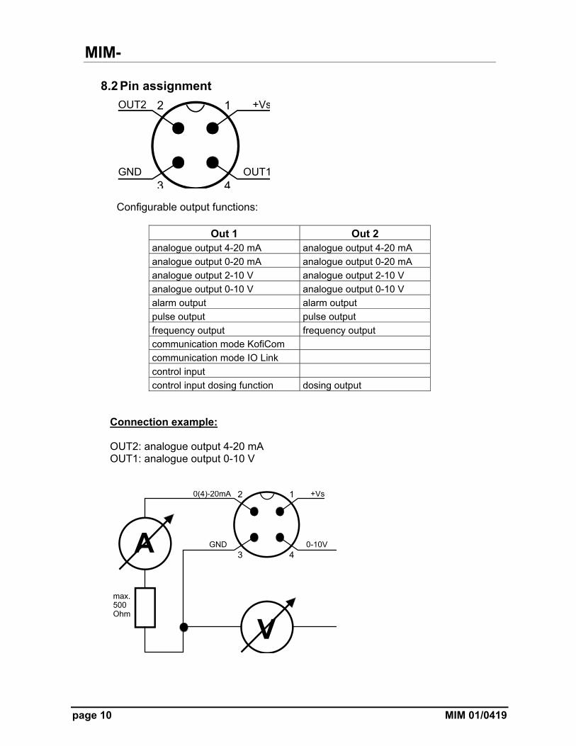
8.2 Pin assignment
Configurable output functions:
Out 1 Out 2 analogue output 4-20 mA analogue output 4-20 mA
analogue output 0-20 mA analogue output 0-20 mA
analogue output 2-10 V analogue output 2-10 V
analogue output 0-10 V analogue output 0-10 V
alarm output alarm output
pulse output pulse output
frequency output frequency output
communication mode KofiCom
communication mode IO Link
control input
control input dosing function dosing output
Connection example: OUT2: analogue output 4-20 mA OUT1: analogue output 0-10 V
MIM-
MIM 01/0419 page 11
9. Operation and menu structure
9.1 General
9.1.1 Operation of the optical buttons
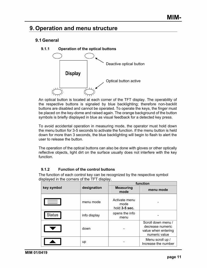
An optical button is located at each corner of the TFT display. The operability of the respective buttons is signaled by blue backlighting; therefore non-backlit buttons are disabled and cannot be operated. To operate the keys, the finger must be placed on the key-dome and raised again. The orange background of the button symbols is briefly displayed in blue as visual feedback for a detected key press. To avoid accidental operation in measuring mode, the operator must hold down the menu button for 3-5 seconds to activate the function. If the menu button is held down for more than 3 seconds, the blue backlighting will begin to flash to alert the user to release the button. The operation of the optical buttons can also be done with gloves or other optically reflective objects, light dirt on the surface usually does not interfere with the key function.
9.1.2 Function of the control buttons
The function of each control key can be recognized by the respective symbol displayed in the corners of the TFT display.
key symbol designation function
Measuring mode
menu mode
menu mode
Activate menu
mode hold 3-5 sec.
-
info display
opens the info menu
-
down -
Scroll down menu / decrease numeric
value when entering numeric value
up -
Menu scroll up / Increase the number
Deactive optical button
Optical button active
MIM-
page 12 MIM 01/0419
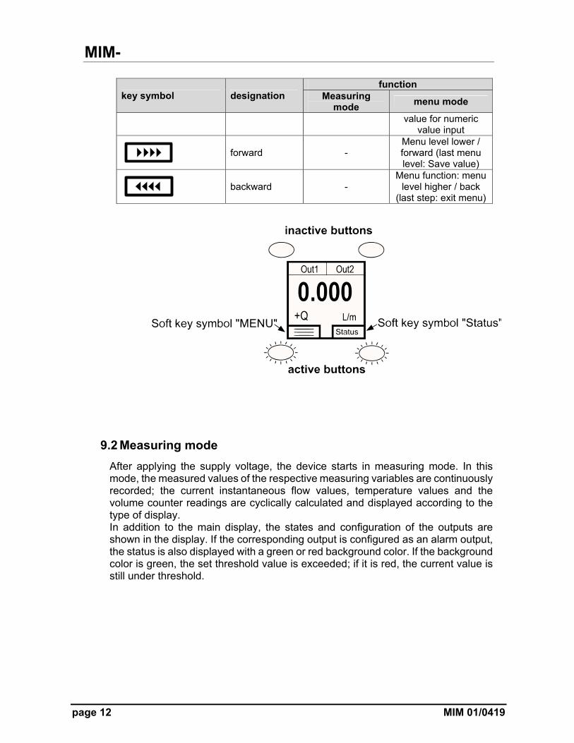
key symbol designation function
Measuring mode
menu mode
value for numeric value input
forward -
Menu level lower / forward (last menu level: Save value)
backward -
Menu function: menu level higher / back
(last step: exit menu)
9.2 Measuring mode
After applying the supply voltage, the device starts in measuring mode. In this mode, the measured values of the respective measuring variables are continuously recorded; the current instantaneous flow values, temperature values and the volume counter readings are cyclically calculated and displayed according to the type of display. In addition to the main display, the states and configuration of the outputs are shown in the display. If the corresponding output is configured as an alarm output, the status is also displayed with a green or red background color. If the background color is green, the set threshold value is exceeded; if it is red, the current value is still under threshold.
MIM-
MIM 01/0419 page 13
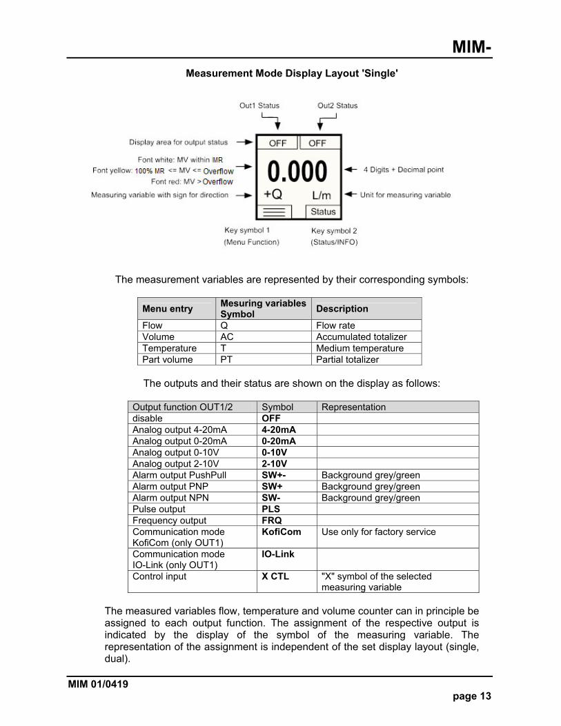
Measurement Mode Display Layout 'Single'
The measurement variables are represented by their corresponding symbols:
Menu entry Mesuring variables Symbol
Description
Flow Q Flow rate Volume AC Accumulated totalizer Temperature T Medium temperature Part volume PT Partial totalizer
The outputs and their status are shown on the display as follows:
Output function OUT1/2 Symbol Representation disable OFF Analog output 4-20mA 4-20mA Analog output 0-20mA 0-20mA Analog output 0-10V 0-10V Analog output 2-10V 2-10V Alarm output PushPull SW+- Background grey/green Alarm output PNP SW+ Background grey/green Alarm output NPN SW- Background grey/green Pulse output PLS Frequency output FRQ Communication mode KofiCom (only OUT1)
KofiCom Use only for factory service
Communication mode IO-Link (only OUT1)
IO-Link
Control input X CTL "X" symbol of the selected measuring variable
The measured variables flow, temperature and volume counter can in principle be assigned to each output function. The assignment of the respective output is indicated by the display of the symbol of the measuring variable. The representation of the assignment is independent of the set display layout (single, dual).
MIM-
page 14 MIM 01/0419
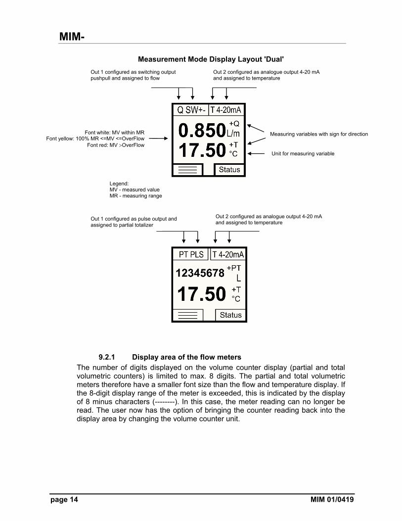
Measurement Mode Display Layout 'Dual'
9.2.1 Display area of the flow meters The number of digits displayed on the volume counter display (partial and total volumetric counters) is limited to max. 8 digits. The partial and total volumetric meters therefore have a smaller font size than the flow and temperature display. If the 8-digit display range of the meter is exceeded, this is indicated by the display of 8 minus characters (--------). In this case, the meter reading can no longer be read. The user now has the option of bringing the counter reading back into the display area by changing the volume counter unit.
Out 1 configured as switching output pushpull and assigned to flow
Out 2 configured as analogue output 4-20 mA and assigned to temperature
Font white: MV within MR Font yellow: 100% MR <=MV <=OverFlow
Font red: MV OverFlow
Measuring variables with sign for direction
Unit for measuring variable
Out 1 configured as pulse output and assigned to partial totalizer
Out 2 configured as analogue output 4-20 mA and assigned to temperature
Legend: MV - measured value MR - measuring range
MIM-
MIM 01/0419 page 15
9.3 Menu Mode
In menu mode, all device parameters can be set. The individual parameters are arranged in menu groups by function. While the menu mode is activated, the signal processing and the outputs are still active in the background. However, all display parameters and outputs are updated after exiting the menu mode or in the measuring mode. Note: The menu mode will exit automatically after a certain time without using the buttons, if the parameter “Menu Timeout” is set not equal to “0”.
9.3.1 Parameter setting
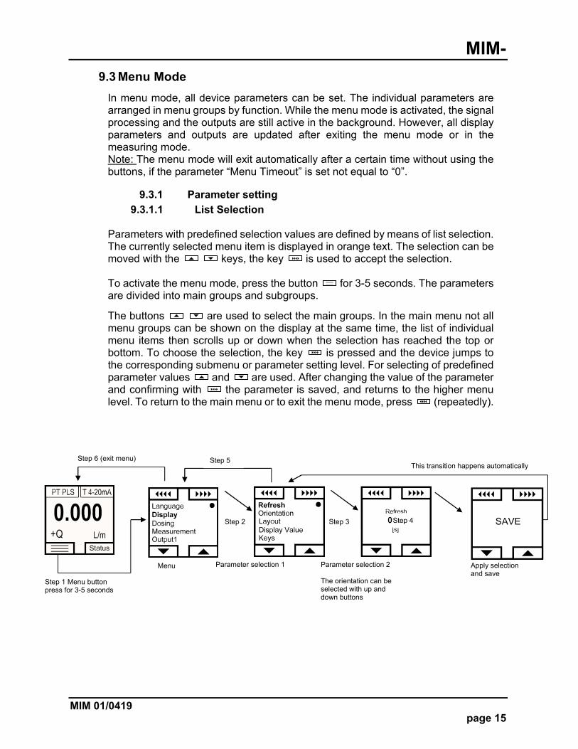
9.3.1.1 List Selection Parameters with predefined selection values are defined by means of list selection. The currently selected menu item is displayed in orange text. The selection can be moved with the keys, the key is used to accept the selection.
To activate the menu mode, press the button for 3-5 seconds. The parameters are divided into main groups and subgroups.
The buttons are used to select the main groups. In the main menu not all menu groups can be shown on the display at the same time, the list of individual menu items then scrolls up or down when the selection has reached the top or bottom. To choose the selection, the key is pressed and the device jumps to the corresponding submenu or parameter setting level. For selecting of predefined parameter values and are used. After changing the value of the parameter and confirming with the parameter is saved, and returns to the higher menu level. To return to the main menu or to exit the menu mode, press (repeatedly).
Step 2
Step 1 Menu button press for 3-5 seconds
Menu
Step 3 Step 4
Parameter selection 1 Parameter selection 2 The orientation can be selected with up and down buttons
Apply selection and save
This transition happens automatically Step 5 Step 6 (exit menu)
MIM-
page 16 MIM 01/0419
9.3.1.2 Numerical value input
When setting parameters with a numerical value, the assigned unit is always displayed below the input field in square brackets in the input function. The maximum size and the number of decimal places are fixed and cannot be changed. After calling the input function, first the left, outer digit is displayed in orange. This position can now be adjusted either with the keys in the value from 0 to 9. By pressing the key , the entry point moves to the right and the next digit can be changed. By pressing the key , the editing point can be moved to the left again. If the editing point is on the far right, the set value is saved by pressing the key again and switched to the higher-level menu function.
10. Device configuration
10.1 Sequence of device parameterization
The flowmeter MIM is pre-configured in factory. Changing the parameters "Measuring range" and "Sensor constant" or "K factor" is therefore not permitted. The adjustment of these parameters is only possible on the part of Kobold-factory. In the event of subsequent changes to volume or throughput units, the dependent parameters are converted and adjusted accordingly. However, the limit parameters of the switching outputs must always be checked and adjusted manually when adjusting volume or throughput units - these are not automatically converted. An accidental change of the parameterization can be revised by the function "Reset factory setting" in the menu Userservice / Reset.
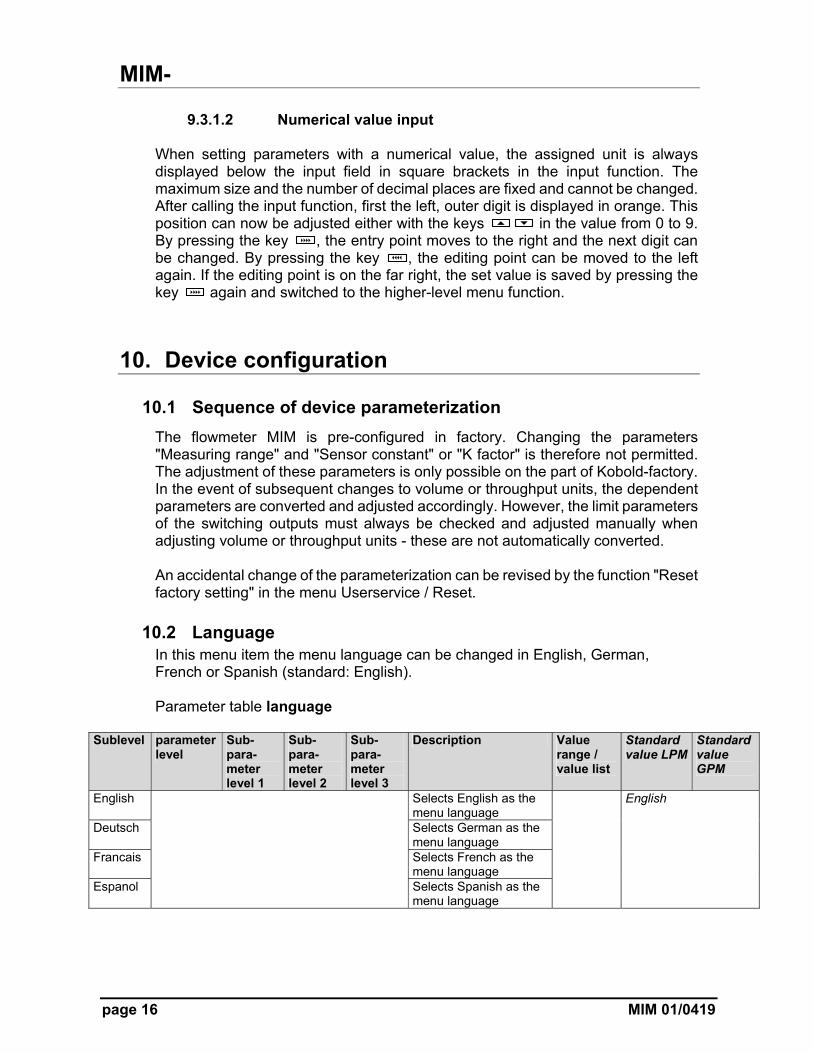
10.2 Language In this menu item the menu language can be changed in English, German, French or Spanish (standard: English). Parameter table language
Sublevel parameter level
Sub-para-meter level 1
Sub-para-meter level 2
Sub-para-meter level 3
Description Value range / value list
Standard value LPM
Standard value GPM
English Selects English as the menu language
English
Deutsch Selects German as the menu language
Francais Selects French as the menu language
Espanol Selects Spanish as the menu language
MIM-
MIM 01/0419 page 17
10.3 Display
10.3.1 Refresh Parameter "Refresh" defines the time interval within which the measuring variables are displayed. The "Refresh rate" can be increased in steps of 0.5 sec. to 10 sec. An increase in the refresh rate time causes an increased "filtering" of the display value.
10.3.2 Orientation With the menu item "Orientation" the display can be rotated either clockwise or counterclockwise in 90 ° increments. As the display rotates, both the display contents and the function of the 4 control buttons are turned.
10.3.3 Layout This parameter can be used to configure the display to either show one measurement variable or two measurement variables.
10.3.4 Display value With the aid of this parameter, the measurement variables provided by the transmitter can be displayed. Depending on the 'Layout' display, either one or two measuring variables can be displayed.
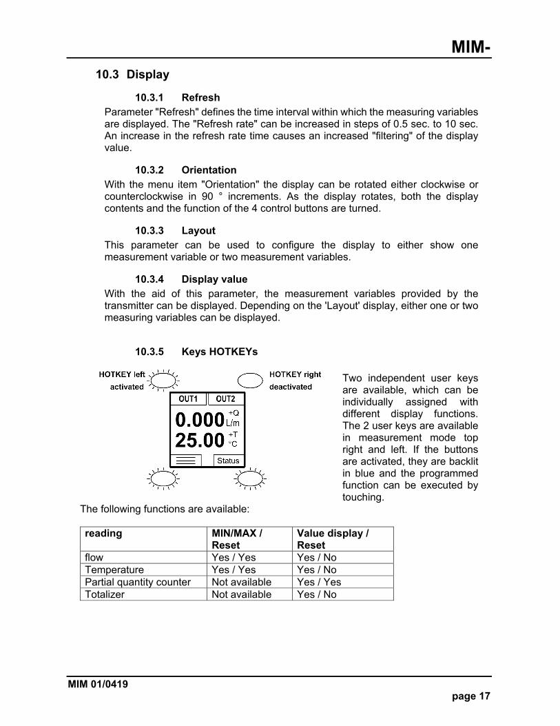
10.3.5 Keys HOTKEYs
Two independent user keys are available, which can be individually assigned with different display functions. The 2 user keys are available in measurement mode top right and left. If the buttons are activated, they are backlit in blue and the programmed function can be executed by touching.
The following functions are available: reading MIN/MAX /
Reset Value display / Reset
flow Yes / Yes Yes / No Temperature Yes / Yes Yes / No Partial quantity counter Not available Yes / Yes Totalizer Not available Yes / No
MIM-
page 18 MIM 01/0419
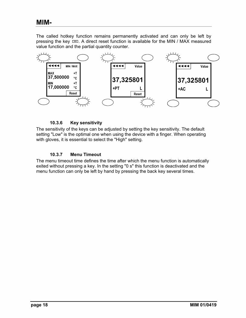
The called hotkey function remains permanently activated and can only be left by pressing the key . A direct reset function is available for the MIN / MAX measured value function and the partial quantity counter.
10.3.6 Key sensitivity
The sensitivity of the keys can be adjusted by setting the key sensitivity. The default setting "Low" is the optimal one when using the device with a finger. When operating with gloves, it is essential to select the "High" setting.
10.3.7 Menu Timeout The menu timeout time defines the time after which the menu function is automatically exited without pressing a key. In the setting "0 s" this function is deactivated and the menu function can only be left by hand by pressing the back key several times.
MIM-
MIM 01/0419 page 19
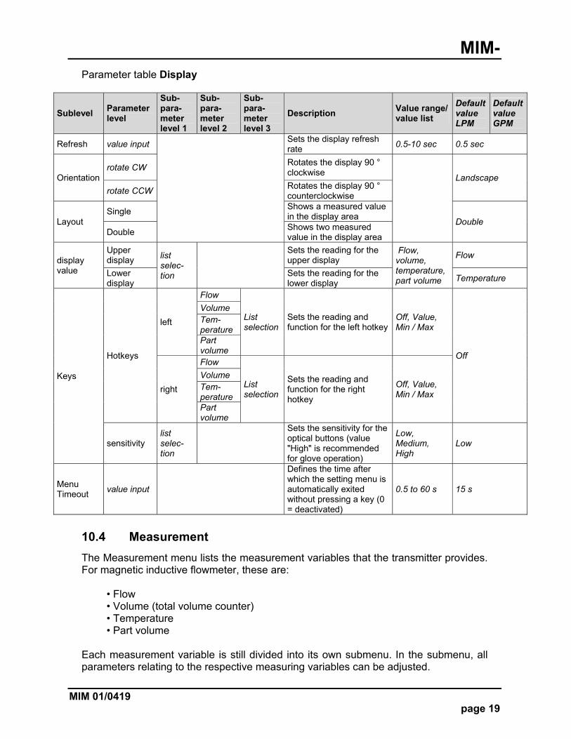
Parameter table Display
Sublevel Parameter level
Sub-para-meter level 1
Sub-para-meter level 2
Sub-para-meter level 3
Description Value range/ value list
Default value LPM
Default value GPM
Refresh value input
Sets the display refresh rate
0.5-10 sec 0.5 sec
Orientation rotate CW
Rotates the display 90 ° clockwise
Landscape
rotate CCW Rotates the display 90 ° counterclockwise
Layout Single
Shows a measured value in the display area
Double Double
Shows two measured value in the display area
display value
Upper display list
selec-tion
Sets the reading for the upper display
Flow, volume, temperature, part volume
Flow
Lower display
Sets the reading for the lower display
Temperature
Keys
Hotkeys
left
Flow
List selection
Sets the reading and function for the left hotkey
Off, Value, Min / Max
Off
Volume Tem-perature Part volume
right
Flow
List selection
Sets the reading and function for the right hotkey
Off, Value, Min / Max
Volume Tem-perature Part volume
sensitivity list selec-tion
Sets the sensitivity for the optical buttons (value "High" is recommended for glove operation)
Low, Medium, High
Low
Menu Timeout
value input
Defines the time after which the setting menu is automatically exited without pressing a key (0 = deactivated)
0.5 to 60 s 15 s
10.4 Measurement
The Measurement menu lists the measurement variables that the transmitter provides. For magnetic inductive flowmeter, these are:
• Flow • Volume (total volume counter) • Temperature • Part volume
Each measurement variable is still divided into its own submenu. In the submenu, all parameters relating to the respective measuring variables can be adjusted.

MIM-
page 20 MIM 01/0419
10.4.1 Flow
10.4.1.1 Unit The displayed unit for the flow measurement can be selected from various predefined standard units. It is also possible to define a user-defined unit ("user"), here the "user unit" must be in LPM (liters / min.) be programmed: e.g. Unit User = 100 LPM, if Q = 500 LPM then the display shows 5 users.
10.4.1.2 Separation The parameter Separation sets the flow rate below which the measured value is set to "0". If this function is active, the flow value "0" is shown in blue colour in the display.
10.4.1.3 Simulation mode See section 10.4.5
10.4.2 Volume
10.4.2.1 Counter type
Absolute: Regardless of the flow direction, the calculated partial volume is added to the counters. Bidirectional: Depending on the flow direction, the calculated partial volume is added or subtracted to the counters. If the measured flow value is negative, the volume value goes down from measurement to measurement (possibly into the negative range).
10.4.2.2 Unit of the total volume counter The parameter "Unit" determines the volume unit of the total volume counter. The listed volume units are available. When changing the volume unit, the current counter reading is converted to the new volume unit.
MIM-
MIM 01/0419 page 21
10.4.3 Temperature
10.4.3.1 Temperature Unit The displayed unit for the temperature measurement can be selected from various default units. It is also possible to define a user-defined unit ("user"), in which case the "user unit" must be programmed in °C. e.g. Unit “user” = 50 °C, if T = 50 °C then the display shows 1 user.
10.4.3.2 Simulation function See section 10.4.5
10.4.4 Part Volume
10.4.4.1 Counter type Absolute: Regardless of the flow direction, the calculated partial volume is added to the counters. Bidirectional: Depending on the flow direction, the calculated partial volume is added or subtracted to the counters. If the measured flow value is negative, the volume value goes down from measurement to measurement (possibly into the negative range).
10.4.4.2 Unit of the part volume counter The parameter "unit" defines the volume unit of all volume meters. The listed volume units are available. When changing the volume unit, the current counter readings are converted to the new volume unit.
10.4.4.3 Memory reset In this menu, the part quantity counter can be reset.
10.4.4.4 Simulation function
See section 10.4.5
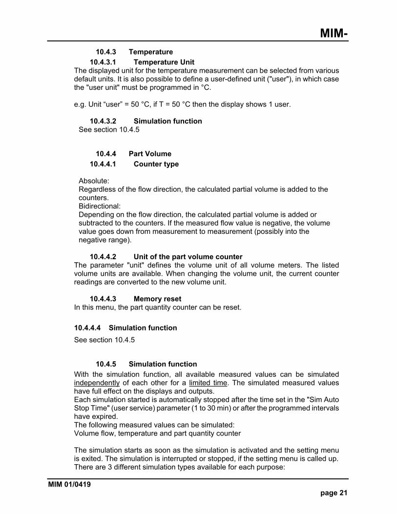
10.4.5 Simulation function
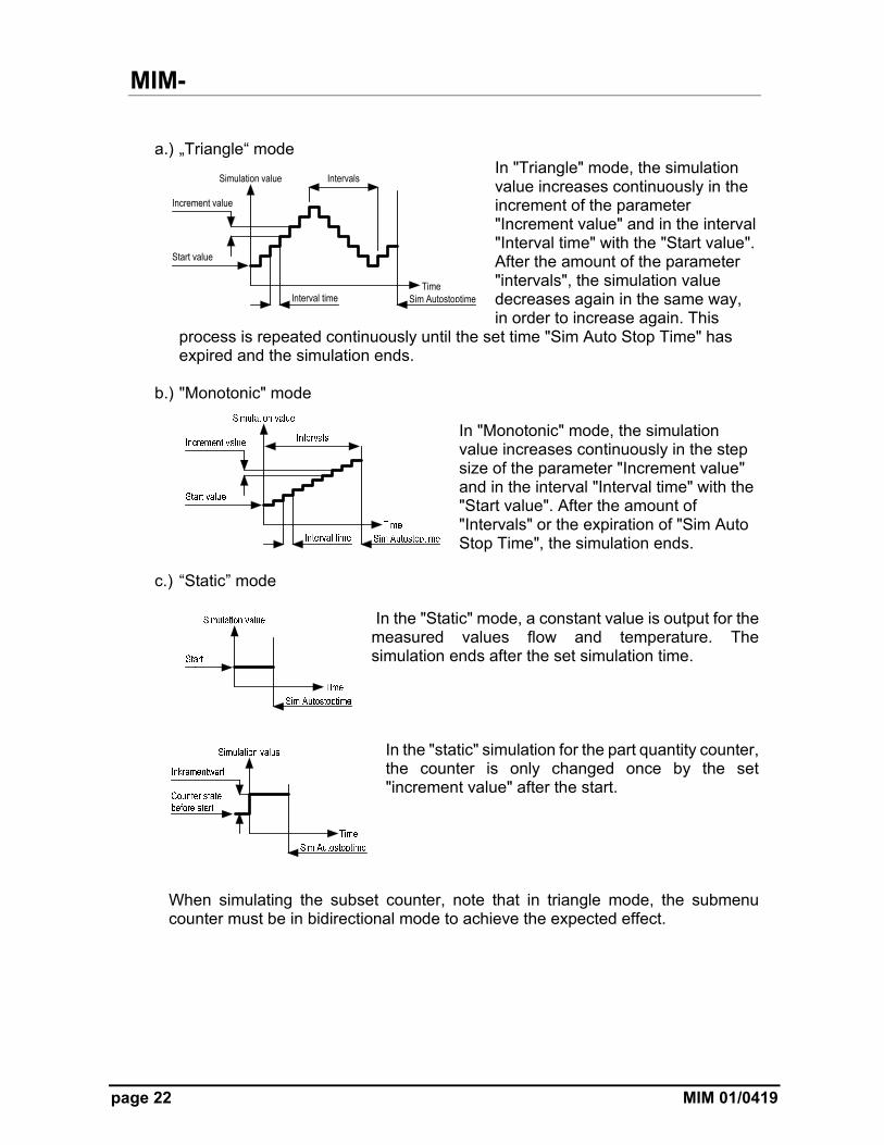
With the simulation function, all available measured values can be simulated independently of each other for a limited time. The simulated measured values have full effect on the displays and outputs. Each simulation started is automatically stopped after the time set in the "Sim Auto Stop Time" (user service) parameter (1 to 30 min) or after the programmed intervals have expired. The following measured values can be simulated: Volume flow, temperature and part quantity counter The simulation starts as soon as the simulation is activated and the setting menu is exited. The simulation is interrupted or stopped, if the setting menu is called up. There are 3 different simulation types available for each purpose:
MIM-
page 22 MIM 01/0419
a.) „Triangle“ mode
In "Triangle" mode, the simulation value increases continuously in the increment of the parameter "Increment value" and in the interval "Interval time" with the "Start value". After the amount of the parameter "intervals", the simulation value decreases again in the same way, in order to increase again. This
process is repeated continuously until the set time "Sim Auto Stop Time" has expired and the simulation ends.
b.) "Monotonic" mode In "Monotonic" mode, the simulation value increases continuously in the step size of the parameter "Increment value" and in the interval "Interval time" with the "Start value". After the amount of "Intervals" or the expiration of "Sim Auto Stop Time", the simulation ends.
c.) “Static” mode
In the "Static" mode, a constant value is output for the measured values flow and temperature. The simulation ends after the set simulation time.
In the "static" simulation for the part quantity counter, the counter is only changed once by the set "increment value" after the start.
When simulating the subset counter, note that in triangle mode, the submenu counter must be in bidirectional mode to achieve the expected effect.
Time
Simulation value
Interval time
Start value
Intervals
Increment value
Sim Autostoptime
MIM-
MIM 01/0419 page 23
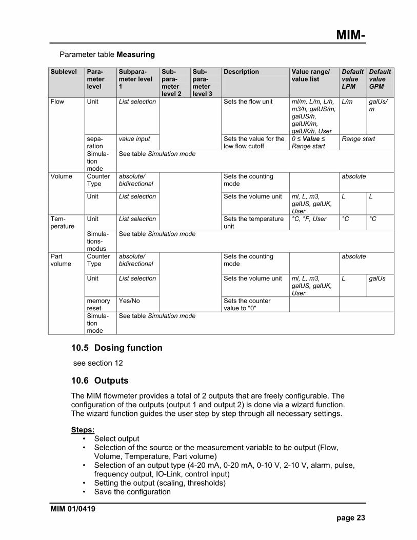
Parameter table Measuring
Sublevel Para-meter level
Subpara-meter level 1
Sub-para-meter level 2
Sub-para-meter level 3
Description Value range/ value list
Default value LPM
Default value GPM
Flow Unit List selection Sets the flow unit ml/m, L/m, L/h, m3/h, galUS/m, galUS/h, galUK/m, galUK/h, User
L/m galUs/m
sepa-ration
value input Sets the value for the low flow cutoff
0 ≤ Value ≤ Range start
Range start
Simula-tion mode
See table Simulation mode
Volume Counter Type
absolute/ bidirectional
Sets the counting mode
absolute
Unit List selection Sets the volume unit ml, L, m3, galUS, galUK, User
L L
Tem-perature
Unit List selection Sets the temperature unit
°C, °F, User °C °C
Simula-tions-modus
See table Simulation mode
Part volume
Counter Type
absolute/ bidirectional
Sets the counting mode
absolute
Unit List selection Sets the volume unit ml, L, m3, galUS, galUK, User
L galUs
memory reset
Yes/No Sets the counter value to "0"
Simula-tion mode
See table Simulation mode
10.5 Dosing function
see section 12
10.6 Outputs
The MIM flowmeter provides a total of 2 outputs that are freely configurable. The configuration of the outputs (output 1 and output 2) is done via a wizard function. The wizard function guides the user step by step through all necessary settings. Steps:
• Select output • Selection of the source or the measurement variable to be output (Flow,
Volume, Temperature, Part volume) • Selection of an output type (4-20 mA, 0-20 mA, 0-10 V, 2-10 V, alarm, pulse,
frequency output, IO-Link, control input) • Setting the output (scaling, thresholds) • Save the configuration

MIM-
page 24 MIM 01/0419
The different output types are optimized for different types of applications. The following table contains the application recommendations for the different output types. If the outputs are not used according to the recommendations, measurement deviations can occur and the desired functionality is not achieved.
Application Output type Analog output (all variants)
Frequency output
Pulse output
Alarm output
Telemetry device Limit monitoring Window monitoring External dosage External volumetric count
Application table output types
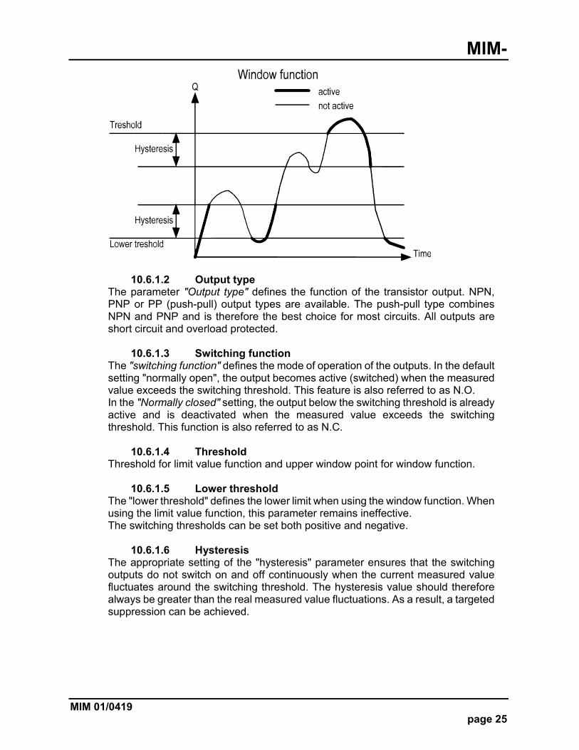
10.6.1 Alarm output The alarm outputs can be parameterized with a limit value function or a window function.
10.6.1.1 Function The parameter "Function" defines the basic function. Limit value function and window function are available. Limit value function: The switching output is active if the current flow rate value is above the switching threshold. It remains active until the measured value has fallen below the switching threshold minus the hysteresis.
Window function: The switching output is active if the current flow measured value is outside a window, which is formed by the "switching threshold" and the "lower threshold". The monitored window decreases in each case by the amount of the "hysteresis". If the switching output is to be active within the window, the parameter "switching function" must be changed from N/O to N/C.
MIM-
MIM 01/0419 page 25
10.6.1.2 Output type The parameter "Output type" defines the function of the transistor output. NPN, PNP or PP (push-pull) output types are available. The push-pull type combines NPN and PNP and is therefore the best choice for most circuits. All outputs are short circuit and overload protected.
10.6.1.3 Switching function The "switching function" defines the mode of operation of the outputs. In the default setting "normally open", the output becomes active (switched) when the measured value exceeds the switching threshold. This feature is also referred to as N.O. In the "Normally closed" setting, the output below the switching threshold is already active and is deactivated when the measured value exceeds the switching threshold. This function is also referred to as N.C.
10.6.1.4 Threshold Threshold for limit value function and upper window point for window function.
10.6.1.5 Lower threshold The "lower threshold" defines the lower limit when using the window function. When using the limit value function, this parameter remains ineffective. The switching thresholds can be set both positive and negative.
10.6.1.6 Hysteresis The appropriate setting of the "hysteresis" parameter ensures that the switching outputs do not switch on and off continuously when the current measured value fluctuates around the switching threshold. The hysteresis value should therefore always be greater than the real measured value fluctuations. As a result, a targeted suppression can be achieved.
MIM-
page 26 MIM 01/0419
10.6.1.7 Filter factor Further suppression of the switching outputs of fluctuating measuring signals can be achieved by setting the parameter "Filter factor". If this parameter is selected greater than one, then the switching threshold must be exceeded in succession with the frequency of the set value before the corresponding switching output is activated. With this function, sporadic limit overruns can be safely suppressed. However, the response time increases according to the level of the "Filter factor".
10.6.2 Analogue outputs
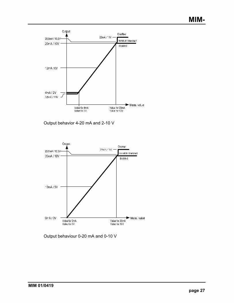
10.6.2.1 Current output 0(4)-20 mA The current output gives a measured variable (flow or temperature) in scaled form as a 0 (4) -20 mA current signal. The current output is scaled via the "Value 20 mA "and" Value 4 mA "(with current output 0-20 mA "Value 0 mA"). By default, the "Value 20 mA" parameter is set to the value for the end of the measuring range, but can be parameterized as desired within the measuring range, but always bigger than the measuring range start value. The parameters "Value 4 mA" / "Value 0 mA" define the measured values for the starting current value, which may also be set freely in the measuring range. Note 1: If the value is set smaller than the end of the measuring range, the accuracy of the output voltage value is reduced. Note 2: The burden on the current output must not exceed 500 Ω.
10.6.2.2 Voltage output 0-10 V / 2-10 V The voltage output outputs a measurement variable (flow or temperature) in scaled form as a 0-10 V / 2-10 V voltage signal. The scaling of the voltage output is done via the parameter "Value 10 V "and "Value 0 V". By default, the "Value 10 V" parameter is set to the value for the end of the measuring range, but can be parameterized as desired within the measuring range, but must always be bigger than the measuring range start value. The parameters "Value 0 V” and “Value 2 V" define the measured values for the start voltage value, which may also be freely set in the measuring range. Note 1: If the value is set smaller than the end of the measuring range, the resolution and accuracy of the output voltage value are reduced.
MIM-
MIM 01/0419 page 27
Output behavior 4-20 mA and 2-10 V
Output behaviour 0-20 mA and 0-10 V
MIM-
page 28 MIM 01/0419
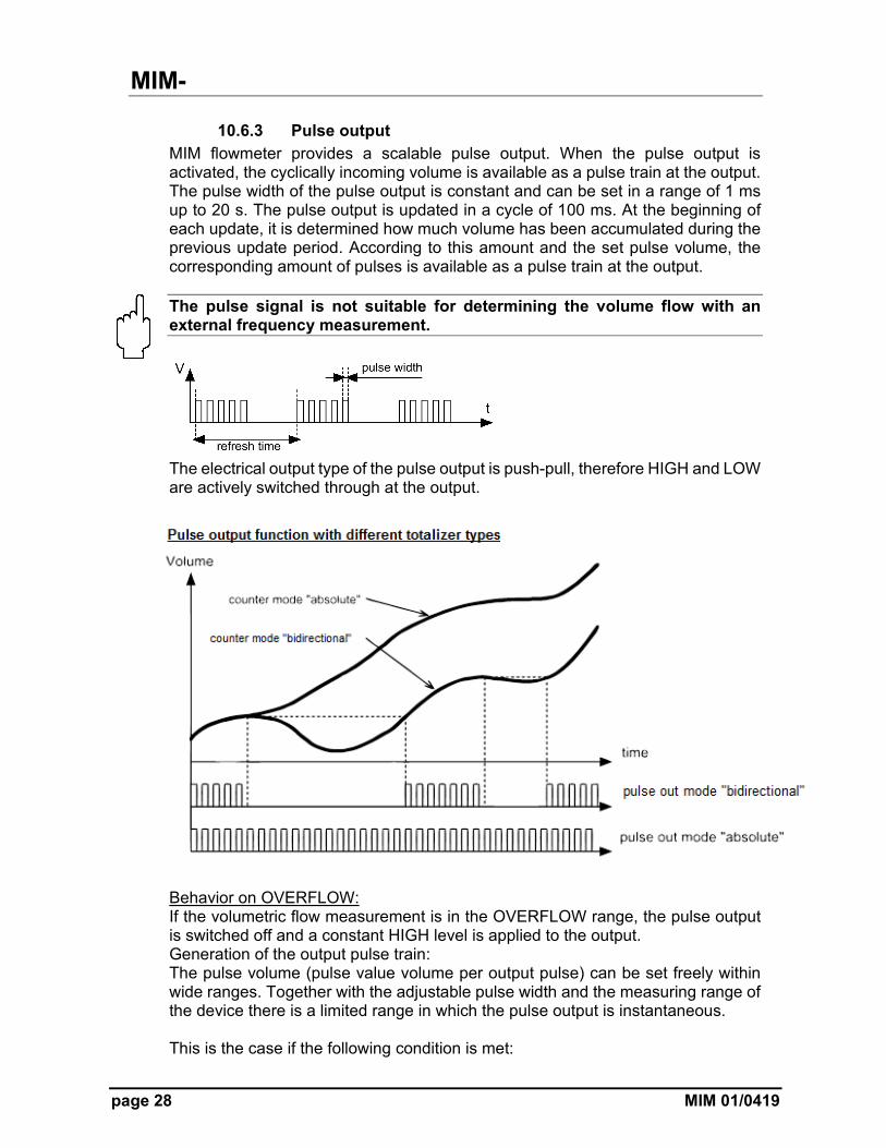
10.6.3 Pulse output MIM flowmeter provides a scalable pulse output. When the pulse output is activated, the cyclically incoming volume is available as a pulse train at the output. The pulse width of the pulse output is constant and can be set in a range of 1 ms up to 20 s. The pulse output is updated in a cycle of 100 ms. At the beginning of each update, it is determined how much volume has been accumulated during the previous update period. According to this amount and the set pulse volume, the corresponding amount of pulses is available as a pulse train at the output. The pulse signal is not suitable for determining the volume flow with an external frequency measurement.
The electrical output type of the pulse output is push-pull, therefore HIGH and LOW are actively switched through at the output.
Behavior on OVERFLOW: If the volumetric flow measurement is in the OVERFLOW range, the pulse output is switched off and a constant HIGH level is applied to the output. Generation of the output pulse train: The pulse volume (pulse value volume per output pulse) can be set freely within wide ranges. Together with the adjustable pulse width and the measuring range of the device there is a limited range in which the pulse output is instantaneous. This is the case if the following condition is met:
MIM-
MIM 01/0419 page 29
/ ∗
22500
or
Pulsevolume L / ∗
If the condition is not met, there may be a time lag of the pulse output. This is particularly undesirable if dosing tasks are to be performed with the pulse signal. The following table shows the different combinations of pulse volume and pulse width for the different measuring ranges, in which the above limiting condition is fulfilled.
Measuring range [LPM]
pulse width [ms]
min. pulse volume [L]
max. pulse rate [pulse/L]
100
20 0.08889 11.25
10 0.04444 22.50
5 0.02222 45.00
1 0.00444 225.00
50
20 0.04444 22.50
10 0.02222 45.00
5 0.01111 90.00
1 0.00222 450.00
25
20 0.02222 45.00
10 0.01111 90.00
5 0.00556 180.00
1 0.00111 900.00
10
20 0.00889 112.50
10 0.00444 225.00
5 0.00222 450.00
1 0.00044 2250.00
03
20 0.0026 375
10 0.0013 750
5 0.0006 1500
1 0.0001 7500
The pulse output only takes place in measuring mode; while the menu mode is active no pulses are given. The pulses accumulated in the menu mode are output as soon as the measuring mode is active again. Depending on the situation, this can also lead to a longer pulse lag.
MIM-
page 30 MIM 01/0419
10.6.3.1 Pulse volume The parameter "Pulse volume" is defined as volume quantity for the output of a pulse; the unit is corresponding to [volume quantity / pulse]. The likewise common pulse rate [pulse / volume unit] corresponds to the reciprocal of the pulse volume. Example: Desired pulse rate at the output 10 pulses / liter => pulse volume = 1 / pulse rate = 1/10 L = 0.1 L
10.6.3.2 Volume unit The volume unit to be set is the input unit for the "Pulse volume" parameter. The definition of a user-defined unit ("user") is also possible and can be programmed in "liters". Example: Unit "user" = 10 [L], pulse volume = 2 [user] The total pulse volume would be 2 * 10 = 20 [L]. After 20 liters, a pulse is output.
10.6.3.1 Pulse width The pulse width of the pulse output is flexibly adjustable from 1 to 20,000 ms.
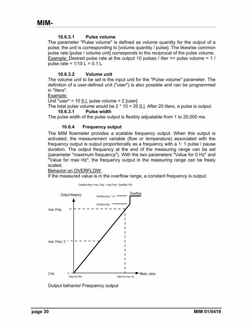
10.6.4 Frequency output The MIM flowmeter provides a scalable frequency output. When this output is activated, the measurement variable (flow or temperature) associated with the frequency output is output proportionally as a frequency with a 1: 1 pulse / pause duration. The output frequency at the end of the measuring range can be set (parameter "maximum frequency"). With the two parameters "Value for 0 Hz" and "Value for max Hz", the frequency output in the measuring range can be freely scaled. Behavior on OVERFLOW: If the measured value is in the overflow range, a constant frequency is output.
Output behavior Frequency output
MIM-
MIM 01/0419 page 31
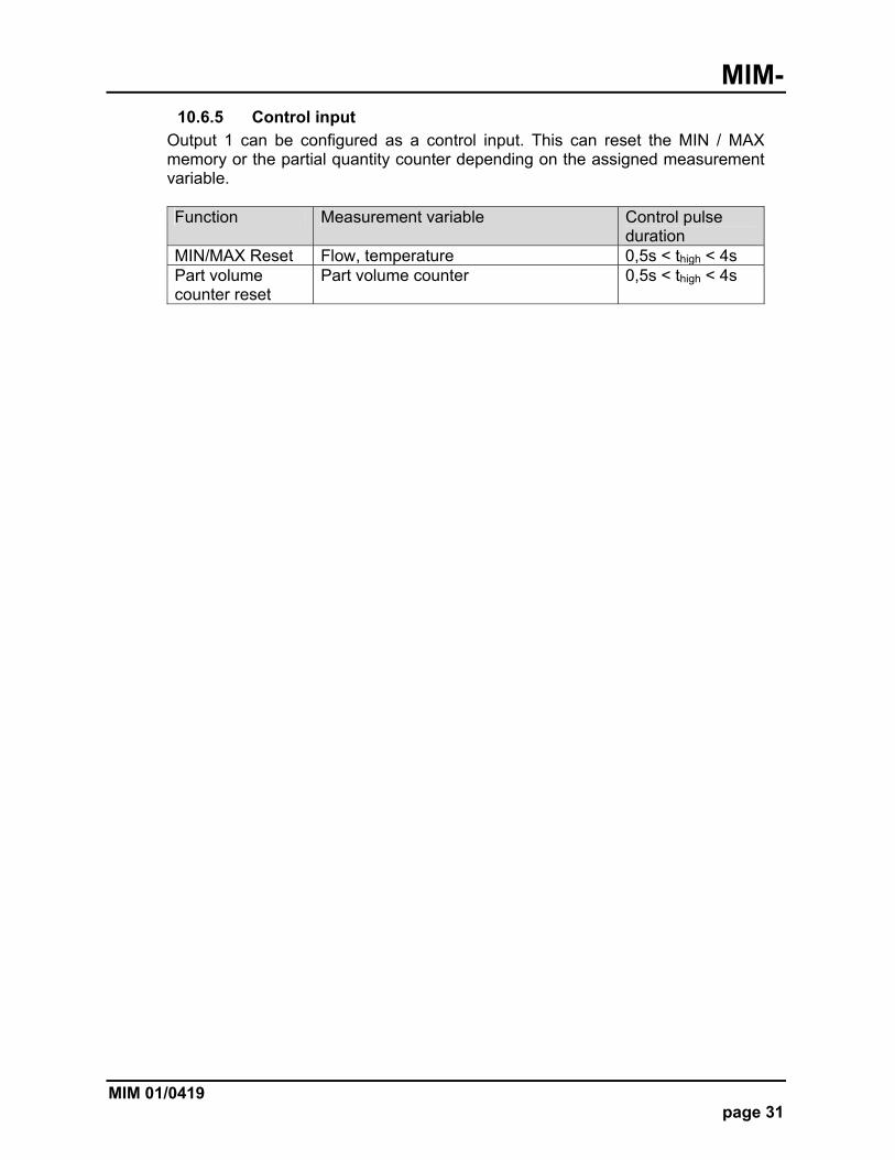
10.6.5 Control input
Output 1 can be configured as a control input. This can reset the MIN / MAX memory or the partial quantity counter depending on the assigned measurement variable. Function Measurement variable Control pulse
duration MIN/MAX Reset Flow, temperature 0,5s < thigh < 4s Part volume counter reset
Part volume counter 0,5s < thigh < 4s

MIM-
page 32 MIM 01/0419
Parameter table Output 1/2 – Flow
Sub-parameter level 1
Sub-parameter level 2
Sub-parameter level 3
Description Value range / value list
Standard value LPM
Standard value GPM
disabled Output deactivated disabled
Alarm output Function List selection
Sets the basic function
Limit function / window function
Limit function
Output Sets the electr. Output
NPN/PNP/PP NPN
switching function
Set the log. switching function
NO/NC NO
threshold Value input Sets the switching threshold
MB start ≤ value ≤ Full scale
1
lower threshold
Sets the lower threshold for window function
Value threshold ≤ value ≤ MB start
1
hysteresis Defines the switching hysteresis
-9999,0 ≤ value ≤ +9999,0
1
filter factor Factor for the switching delay x100 ms
0x ≤ value ≤ 60x 0
4-20 mA Value 4 mA Measured value for 4 mA output
MB-start ≤ value ≤ Wert 20 mA
0
Value 20 mA Measured value for 20 mA output
Value 4 mA ≤ value ≤ Full scale
100
0-20 mA Value 0 mA Measured value for 0 mA output
MB start ≤ value ≤ value 20 mA
0
Value 20 mA Measured value for 20 mA output
Value for 0 mA ≤ value ≤ Full scale
100
2-10 V Value 2 V Measured value for 2 V output
MB start ≤ value ≤ value 10 V
0
Value 10 V Measured value for 10 V output
Value for 2 V ≤ value ≤ Full scale
100
0-10 V Value 0 V Measured value for 0 V output
MB start ≤ value ≤ value 10 V
0
Value 10 V Measured value for 10 V output
Value for 0 V ≤ value ≤ Full scale
100
Frequency output
max. frequency
Frequency output at "value at max. Hz"
50-1000 Hz 500 Hz
overflow Overflow value in % of the value "max.frequency"
1-100 [%] 1%
Value at 0 Hz Value at 0 Hz MB start ≤ value ≤ value at max. Hz
0
Value at max. Hz
Value at "maximum frequency"
Value for 0 Hz <value ≤ Full scale
100
Control input (only output 1)
Control function for MIN / MAX memory reset
OFF, memory reset
Aus
KofiCom Factory calibration mode on output 1
IO-Link This mode activates the IO-Link function on output 1
MIM-
MIM 01/0419 page 33
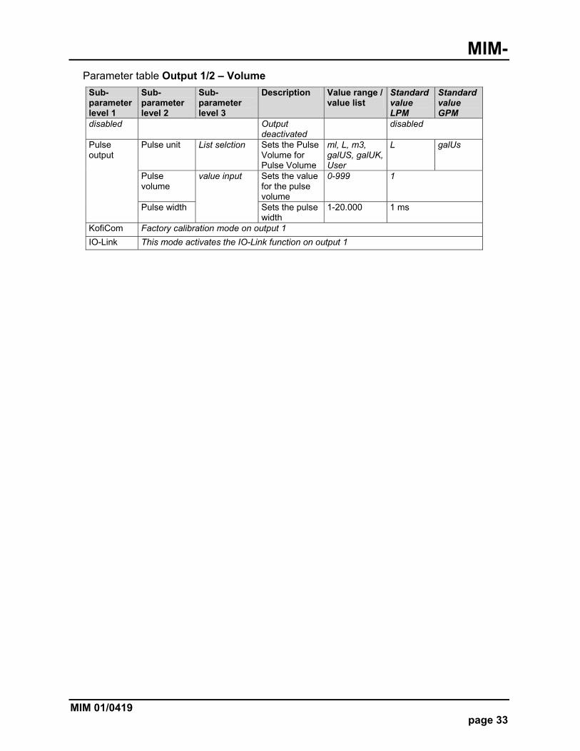
Parameter table Output 1/2 – Volume
Sub-parameter level 1
Sub-parameter level 2
Sub-parameter level 3
Description Value range / value list
Standard value LPM
Standard value GPM
disabled Output deactivated
disabled
Pulse output
Pulse unit List selction Sets the Pulse Volume for Pulse Volume
ml, L, m3, galUS, galUK, User
L galUs
Pulse volume
value input Sets the value for the pulse volume
0-999 1
Pulse width Sets the pulse width
1-20.000 1 ms
KofiCom Factory calibration mode on output 1
IO-Link This mode activates the IO-Link function on output 1
MIM-
page 34 MIM 01/0419
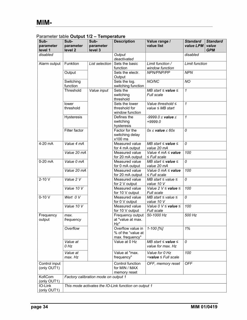
Parameter table Output 1/2 – Temperature Sub-parameter level 1
Sub-parameter level 2
Sub-parameter level 3
Description Value range / value list
Standard value LPM
Standard value GPM
disabled Output deactivated
disabled
Alarm output Funktion List selection Sets the basic function
Limit function / window function
Limit function
Output Sets the electr. Output
NPN/PNP/PP NPN
Switching function
Sets the log. switching function
NO/NC NO
Threshold Value input Sets the switching threshold
MB start ≤ value ≤ Full scale
1
lower threshold
Sets the lower threshold for window function
Value threshold ≤ value ≤ MB start
1
Hysteresis Defines the switching hysteresis
-9999.0 ≤ value ≤ +9999.0
1
Filter factor Factor for the switching delay x100 ms
0x ≤ value ≤ 60x 0
4-20 mA Value 4 mA Measured value for 4 mA output
MB start ≤ value ≤ value 20 mA
0
Value 20 mA Measured value for 20 mA output
Value 4 mA ≤ value ≤ Full scale
100
0-20 mA Value 0 mA Measured value for 0 mA output
MB start ≤ value ≤ value 20 mA
0
Value 20 mA Measured value for 20 mA output
Value 0 mA ≤ value ≤ Full scale
100
2-10 V Value 2 V Measured value for 2 V output
MB start ≤ value ≤ value 10 V
0
Value 10 V Measured value for 10 V output
Value 2 V ≤ value ≤ Full scale
100
0-10 V Wert 0 V Measured value for 0 V output
MB start ≤ value ≤ value 10 V
0
Value 10 V Measured value for 10 V output
Value 0 V ≤ value ≤ Full scale
100
Frequency output
max. frequency
Frequency output at "value at max. Hz"
50-1000 Hz 500 Hz
Overflow Overflow value in % of the “value at max. frequency"
1-100 [%] 1%
Value at 0 Hz
Value at 0 Hz MB start ≤ value ≤ value for max. Hz
0
Value at max. Hz
Value at "max. frequency"
Value for 0 Hz <value ≤ Full scale
100
Control input (only OUT1)
Control function for MIN / MAX memory reset
OFF, memory reset OFF
KofiCom (only OUT1)
Factory calibration mode on output 1
IO-Link (only OUT1)
This mode activates the IO-Link function on output 1
MIM-
MIM 01/0419 page 35
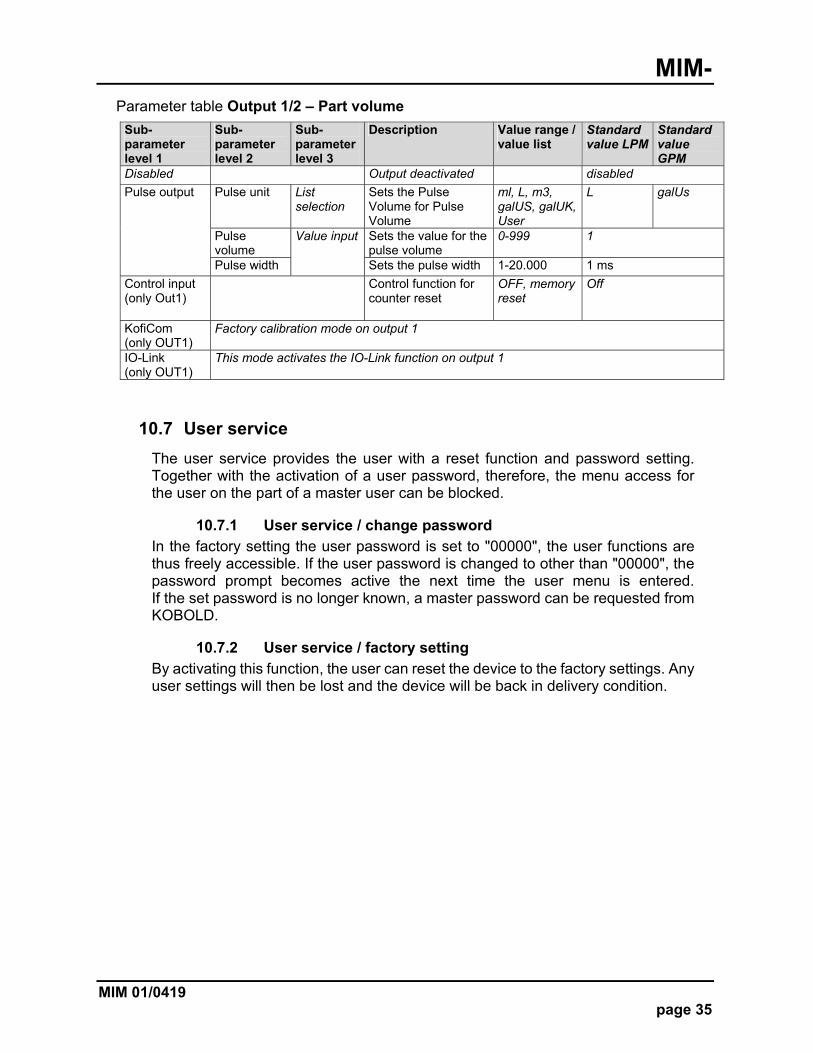
Parameter table Output 1/2 – Part volume
Sub-parameter level 1
Sub-parameter level 2
Sub-parameter level 3
Description Value range / value list
Standard value LPM
Standard value GPM
Disabled Output deactivated disabled
Pulse output Pulse unit List selection
Sets the Pulse Volume for Pulse Volume
ml, L, m3, galUS, galUK, User
L galUs
Pulse volume
Value input Sets the value for the pulse volume
0-999 1
Pulse width Sets the pulse width 1-20.000 1 ms
Control input (only Out1)
Control function for counter reset
OFF, memory reset
Off
KofiCom (only OUT1)
Factory calibration mode on output 1
IO-Link (only OUT1)
This mode activates the IO-Link function on output 1
10.7 User service
The user service provides the user with a reset function and password setting. Together with the activation of a user password, therefore, the menu access for the user on the part of a master user can be blocked.
10.7.1 User service / change password In the factory setting the user password is set to "00000", the user functions are thus freely accessible. If the user password is changed to other than "00000", the password prompt becomes active the next time the user menu is entered. If the set password is no longer known, a master password can be requested from KOBOLD.
10.7.2 User service / factory setting
By activating this function, the user can reset the device to the factory settings. Any user settings will then be lost and the device will be back in delivery condition.
MIM-
page 36 MIM 01/0419
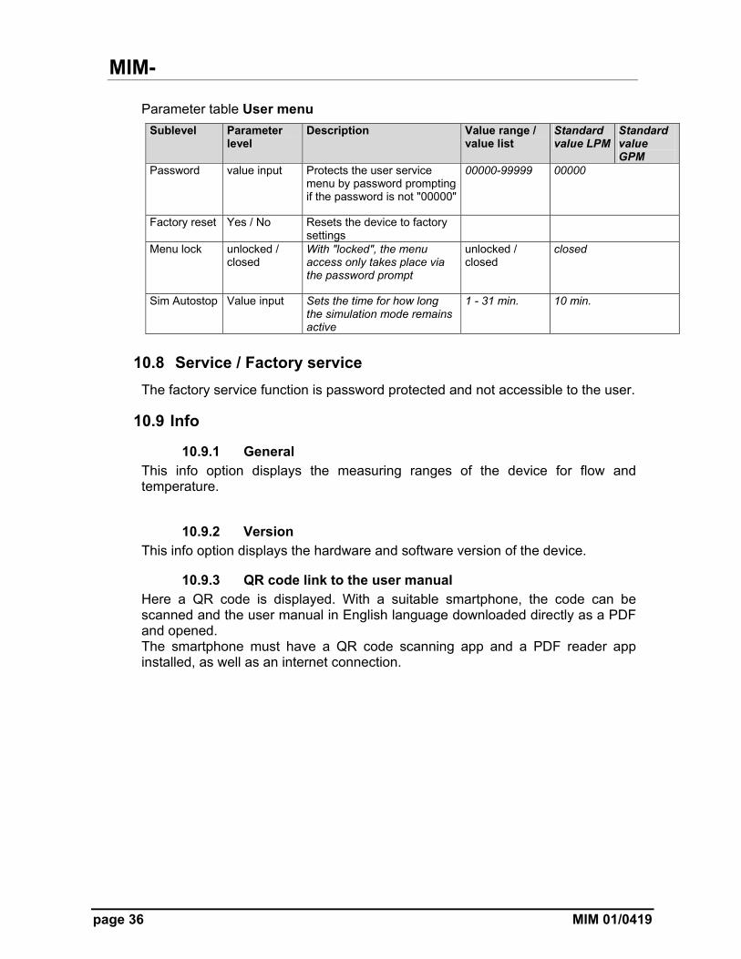
Parameter table User menu
Sublevel Parameter level
Description Value range / value list
Standard value LPM
Standard value GPM
Password value input Protects the user service menu by password prompting if the password is not "00000"
00000-99999 00000
Factory reset Yes / No Resets the device to factory settings
Menu lock unlocked / closed
With "locked", the menu access only takes place via the password prompt
unlocked / closed
closed
Sim Autostop Value input Sets the time for how long the simulation mode remains active
1 - 31 min. 10 min.
10.8 Service / Factory service
The factory service function is password protected and not accessible to the user.
10.9 Info
10.9.1 General
This info option displays the measuring ranges of the device for flow and temperature.
10.9.2 Version This info option displays the hardware and software version of the device.
10.9.3 QR code link to the user manual Here a QR code is displayed. With a suitable smartphone, the code can be scanned and the user manual in English language downloaded directly as a PDF and opened. The smartphone must have a QR code scanning app and a PDF reader app installed, as well as an internet connection.
MIM-
MIM 01/0419 page 37
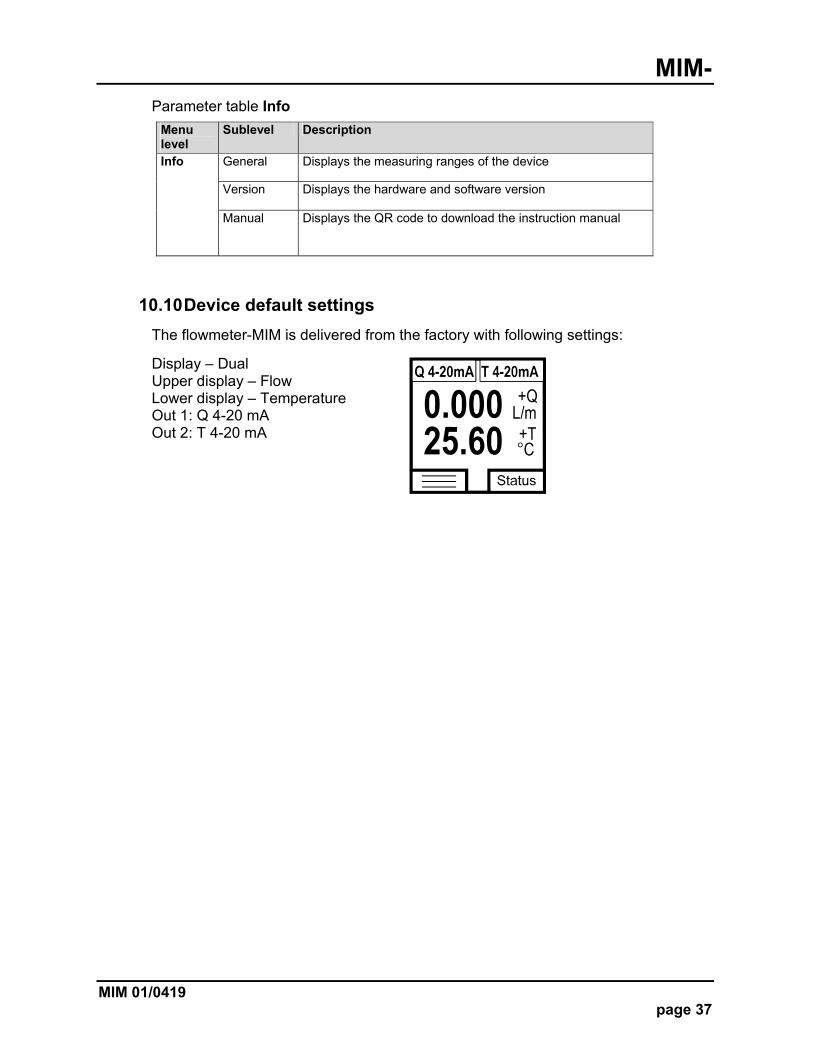
Parameter table Info
Menu level
Sublevel Description
Info General Displays the measuring ranges of the device
Version Displays the hardware and software version
Manual Displays the QR code to download the instruction manual
10.10 Device default settings
The flowmeter-MIM is delivered from the factory with following settings:
Display – Dual Upper display – Flow Lower display – Temperature Out 1: Q 4-20 mA Out 2: T 4-20 mA
MIM-
page 38 MIM 01/0419
11. Status
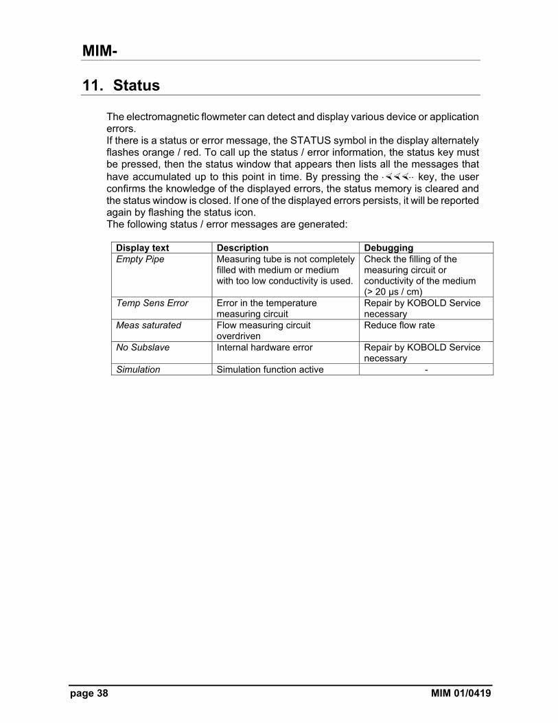
The electromagnetic flowmeter can detect and display various device or application errors. If there is a status or error message, the STATUS symbol in the display alternately flashes orange / red. To call up the status / error information, the status key must be pressed, then the status window that appears then lists all the messages that have accumulated up to this point in time. By pressing the key, the user confirms the knowledge of the displayed errors, the status memory is cleared and the status window is closed. If one of the displayed errors persists, it will be reported again by flashing the status icon. The following status / error messages are generated:
Display text Description Debugging Empty Pipe Measuring tube is not completely
filled with medium or medium with too low conductivity is used.
Check the filling of the measuring circuit or conductivity of the medium (> 20 μs / cm)
Temp Sens Error Error in the temperature measuring circuit
Repair by KOBOLD Service necessary
Meas saturated Flow measuring circuit overdriven
Reduce flow rate
No Subslave Internal hardware error Repair by KOBOLD Service necessary
Simulation Simulation function active -
MIM-
MIM 01/0419 page 39
12. Dosing function
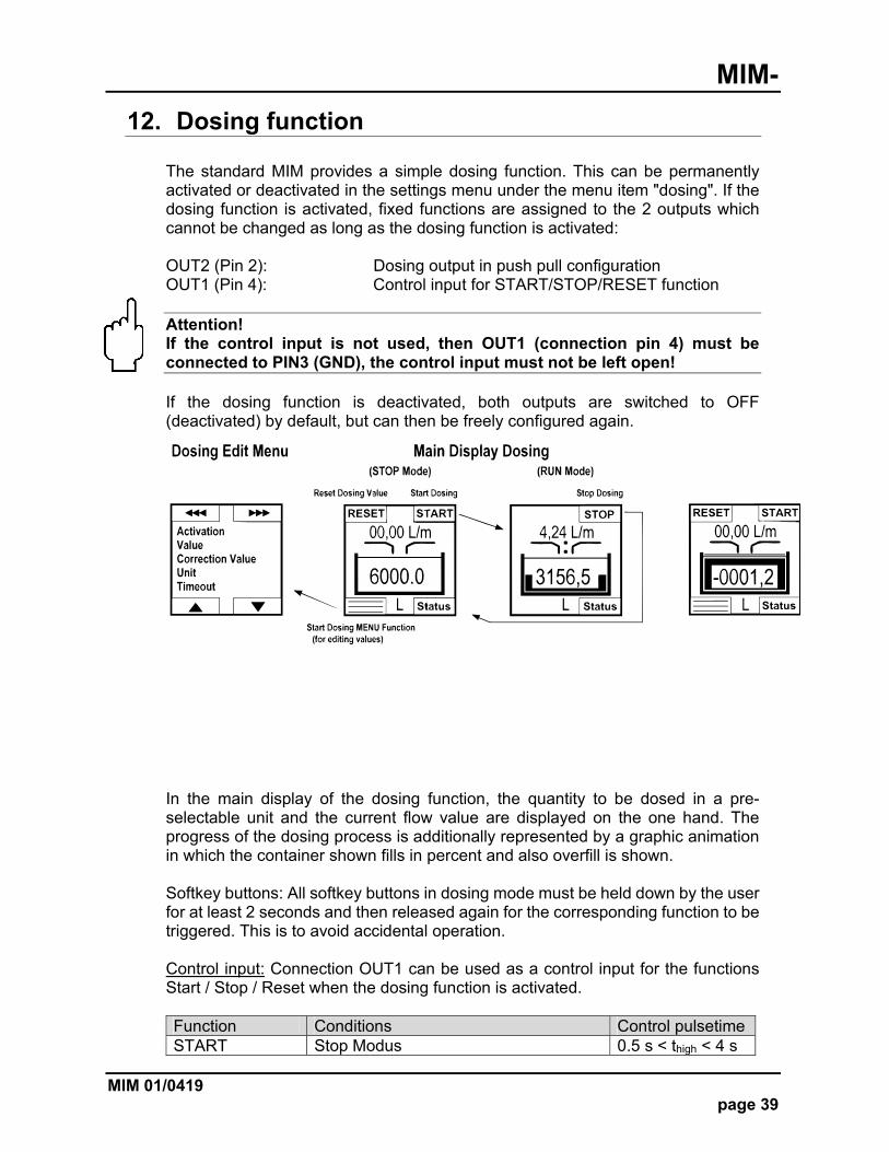
The standard MIM provides a simple dosing function. This can be permanently activated or deactivated in the settings menu under the menu item "dosing". If the dosing function is activated, fixed functions are assigned to the 2 outputs which cannot be changed as long as the dosing function is activated: OUT2 (Pin 2): Dosing output in push pull configuration OUT1 (Pin 4): Control input for START/STOP/RESET function Attention! If the control input is not used, then OUT1 (connection pin 4) must be connected to PIN3 (GND), the control input must not be left open! If the dosing function is deactivated, both outputs are switched to OFF (deactivated) by default, but can then be freely configured again.
In the main display of the dosing function, the quantity to be dosed in a pre-selectable unit and the current flow value are displayed on the one hand. The progress of the dosing process is additionally represented by a graphic animation in which the container shown fills in percent and also overfill is shown. Softkey buttons: All softkey buttons in dosing mode must be held down by the user for at least 2 seconds and then released again for the corresponding function to be triggered. This is to avoid accidental operation. Control input: Connection OUT1 can be used as a control input for the functions Start / Stop / Reset when the dosing function is activated. Function Conditions Control pulsetime START Stop Modus 0.5 s < thigh < 4 s
MIM-
page 40 MIM 01/0419
STOP Run Modus 0.5 s < thigh < 4 s RESET Stop Modus thigh > 5 s
MIM-
MIM 01/0419 page 41
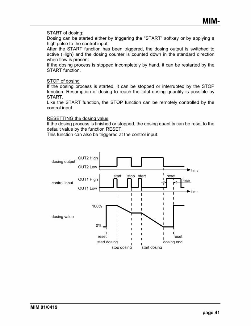
START of dosing: Dosing can be started either by triggering the "START" softkey or by applying a high pulse to the control input. After the START function has been triggered, the dosing output is switched to active (High) and the dosing counter is counted down in the standard direction when flow is present. If the dosing process is stopped incompletely by hand, it can be restarted by the START function. STOP of dosing If the dosing process is started, it can be stopped or interrupted by the STOP function. Resumption of dosing to reach the total dosing quantity is possible by START. Like the START function, the STOP function can be remotely controlled by the control input. RESETTING the dosing value If the dosing process is finished or stopped, the dosing quantity can be reset to the default value by the function RESET. This function can also be triggered at the control input.

MIM-
page 42 MIM 01/0419
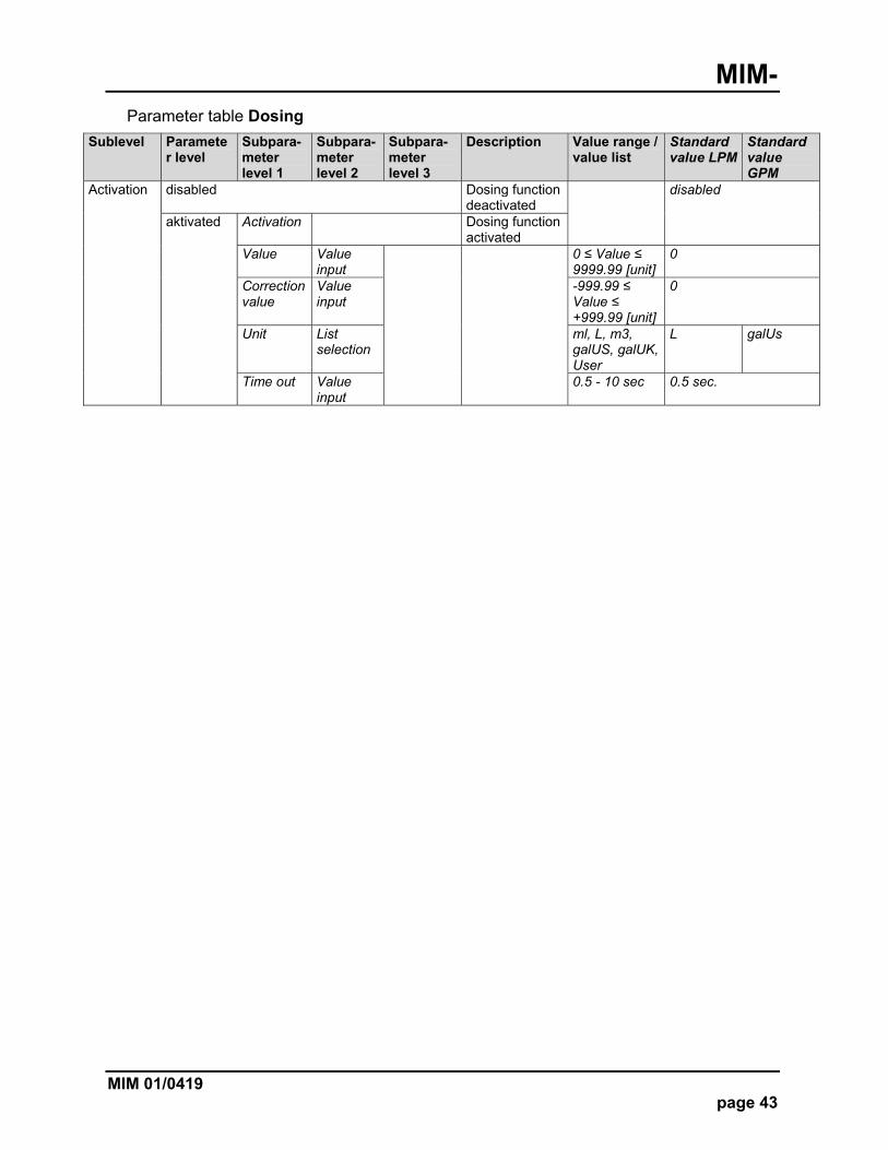
Description of dosing parameters Dosing quantity "Value" Parameter "Value" determines the dosing volume. The volume unit is specified in the "Unit" parameter. The maximum size is limited to 9999.9 (one digit after the decimal point). The absolute quantity can be extended or restricted by a suitable choice of dosing unit. Dosing unit "Unit" Parameter "Unit" defines the dosing volume unit. The choices are: mL, L, m3, gal US, gal UK, barrel, user Dosing correction value "Correction value" The "Correction value" parameter can be used to correct a system-related, constant "incorrect dosing" without having to change the actual dosing quantity. The correction value can be both positive and negative. If the system doses a smaller volume than intended, the correction value must be positive, but negative for a larger real volume. e.g. Dosing quantity = 10 L Correction value = -1 L In this case, the metering counter will count from 10 L to '0', but will stop at 1 L because the quantity to be metered is 9 L calculated on the basis of the correction value of -1 L. With a correction value of +1 L, the dosing counter will stop counting at -1 L, because the dosing amount is calculated to be 11 L. 10 - (- 1 L) = 11 L The adjustable value of the correction value must always be: (Value + Correction Value)> 0 If this condition is not met, this will be indicated by a warning message and the correction value will be preset to the value - (Value-0.1). Dosing parameter "Timeout" During the dosing process, the presence of a flow value not equal to 0 is constantly monitored. For this purpose, the parameter "Timeout" is used to set the time after which the status message "Time Out" is triggered. The timeout value can be set between 0.5 sec and 10 sec.
MIM-
MIM 01/0419 page 43
Parameter table Dosing
Sublevel Parameter level
Subpara-meter level 1
Subpara-meter level 2
Subpara-meter level 3
Description Value range / value list
Standard value LPM
Standard value GPM
Activation disabled Dosing function deactivated
disabled
aktivated Activation Dosing function activated
Value Value input
0 ≤ Value ≤ 9999.99 [unit]
0
Correction value
Value input
-999.99 ≤ Value ≤ +999.99 [unit]
0
Unit List selection
ml, L, m3, galUS, galUK, User
L galUs
Time out Value input
0.5 - 10 sec 0.5 sec.
MIM-
page 44 MIM 01/0419
13. IO-Link function
As of firmware version REV181121, the MIM flowmeter has an IO-Link communication interface as standard. Process and diagnostic data can be accessed directly via this interface and the device can be parameterized. The IO-Link interface can be used if OUT1 is configured manually in the settings menu to "IO-Link". To ensure that the IO-Link device can be operated correctly on the connected IO-Link master, it is necessary to install the device description file matching the device. The device description files (IODD) are available in the IODD finder, ioddfinder.io-link.com. Further information on IO-Link is available on the homepage www.io-link.com.
13.1 Specification
Manufacturer ID 1105 (decimal), 0x0451 (hex) Manufacturer name Kobold Messring GmbH IO-Link specification V1.1 Bit rate COM3 Minimum cycle time 1.1 ms SIO mode yes (OUT1 in configuration IO-Link) Block parameterization yes Ready for operation 10 sec. Max. Cable length 20 m
MIM-
MIM 01/0419 page 45
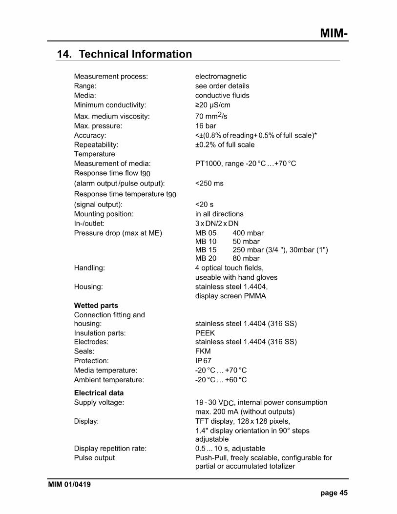
14. Technical Information
Measurement process: electromagnetic Range: see order details Media: conductive fluids Minimum conductivity: ≥20 µS/cm
Max. medium viscosity: 70 mm2/s Max. pressure: 16 bar Accuracy: <±(0.8% of reading+ 0.5% of full scale)* Repeatability: ±0.2% of full scale Temperature Measurement of media: PT1000, range -20 °C …+70 °C Response time flow t90 (alarm output /pulse output): <250 ms
Response time temperature t90
(signal output): <20 s Mounting position: in all directions In-/outlet: 3 x DN/2 x DN Pressure drop (max at ME) MB 05 400 mbar MB 10 50 mbar MB 15 250 mbar (3/4 "), 30mbar (1") MB 20 80 mbar Handling: 4 optical touch fields, useable with hand gloves Housing: stainless steel 1.4404, display screen PMMA Wetted parts Connection fitting and housing: stainless steel 1.4404 (316 SS) Insulation parts: PEEK Electrodes: stainless steel 1.4404 (316 SS) Seals: FKM Protection: IP 67 Media temperature: -20 °C … +70 °C Ambient temperature: -20 °C … +60 °C
Electrical data Supply voltage: 19 - 30 VDC, internal power consumption max. 200 mA (without outputs) Display: TFT display, 128 x 128 pixels, 1.4" display orientation in 90° steps adjustable Display repetition rate: 0.5 ... 10 s, adjustable Pulse output Push-Pull, freely scalable, configurable for partial or accumulated totalizer
MIM-
page 46 MIM 01/0419
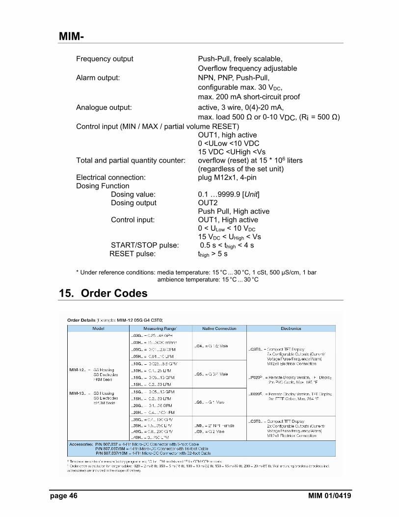
Frequency output Push-Pull, freely scalable, Overflow frequency adjustable Alarm output: NPN, PNP, Push-Pull, configurable max. 30 VDC, max. 200 mA short-circuit proof
Analogue output: active, 3 wire, 0(4)-20 mA, max. load 500 Ω or 0-10 VDC, (Ri = 500 Ω) Control input (MIN / MAX / partial volume RESET) OUT1, high active 0 <ULow <10 VDC 15 VDC <UHigh <Vs Total and partial quantity counter: overflow (reset) at 15 * 106 liters (regardless of the set unit) Electrical connection: plug M12x1, 4-pin Dosing Function Dosing value: 0.1 …9999.9 [Unit] Dosing output OUT2
Push Pull, High active Control input: OUT1, High active 0 < ULow < 10 VDC
15 VDC < UHigh < Vs START/STOP pulse: 0.5 s < thigh < 4 s RESET pulse: thigh > 5 s
* Under reference conditions: media temperature: 15 °C ... 30 °C, 1 cSt, 500 µS/cm, 1 bar ambience temperature: 15 °C ... 30 °C
15. Order Codes
MIM-
MIM 01/0419 page 47
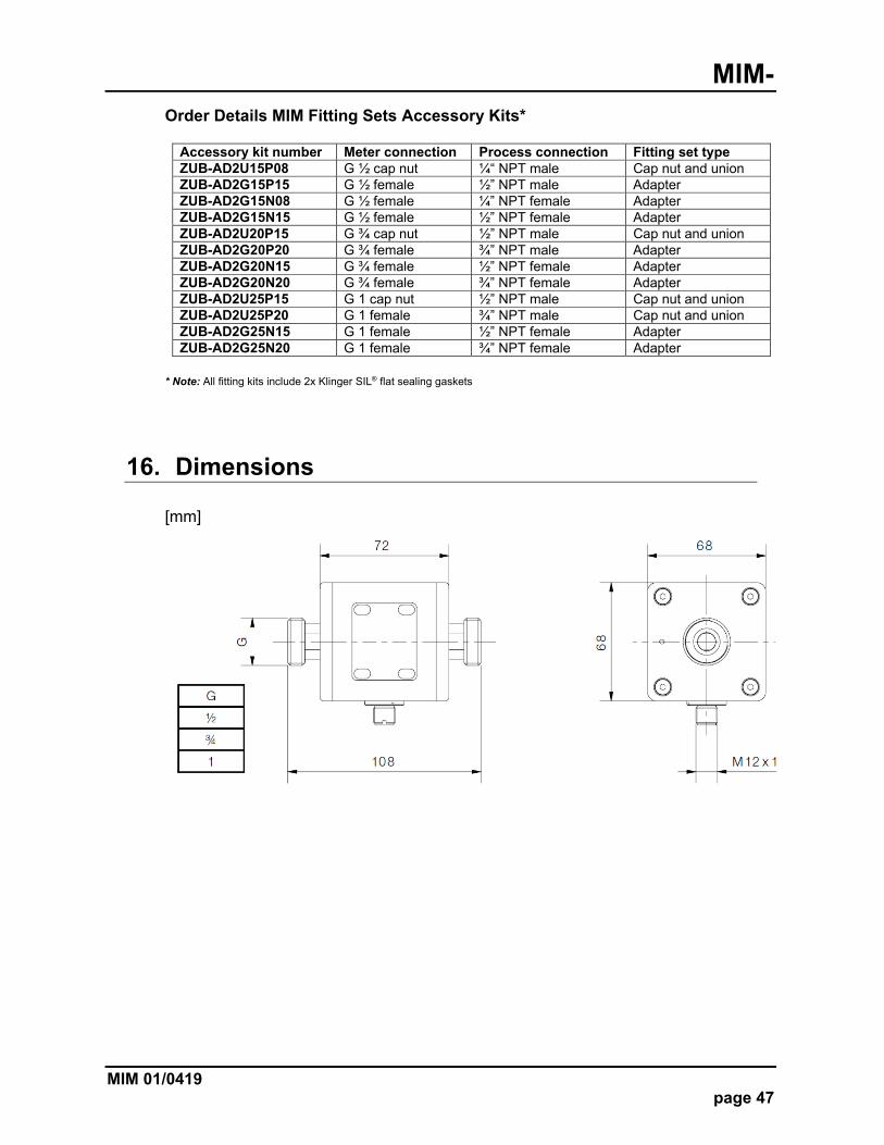
Order Details MIM Fitting Sets Accessory Kits*
Accessory kit number Meter connection Process connection Fitting set type ZUB-AD2U15P08 G ½ cap nut ¼“ NPT male Cap nut and union ZUB-AD2G15P15 G ½ female ½” NPT male Adapter ZUB-AD2G15N08 G ½ female ¼” NPT female Adapter ZUB-AD2G15N15 G ½ female ½” NPT female Adapter ZUB-AD2U20P15 G ¾ cap nut ½” NPT male Cap nut and union ZUB-AD2G20P20 G ¾ female ¾” NPT male Adapter ZUB-AD2G20N15 G ¾ female ½” NPT female Adapter ZUB-AD2G20N20 G ¾ female ¾” NPT female Adapter ZUB-AD2U25P15 G 1 cap nut ½” NPT male Cap nut and union ZUB-AD2U25P20 G 1 female ¾” NPT male Cap nut and union ZUB-AD2G25N15 G 1 female ½” NPT female Adapter ZUB-AD2G25N20 G 1 female ¾” NPT female Adapter
* Note: All fitting kits include 2x Klinger SIL® flat sealing gaskets
16. Dimensions
[mm]
MIM-
page 48 MIM 01/0419
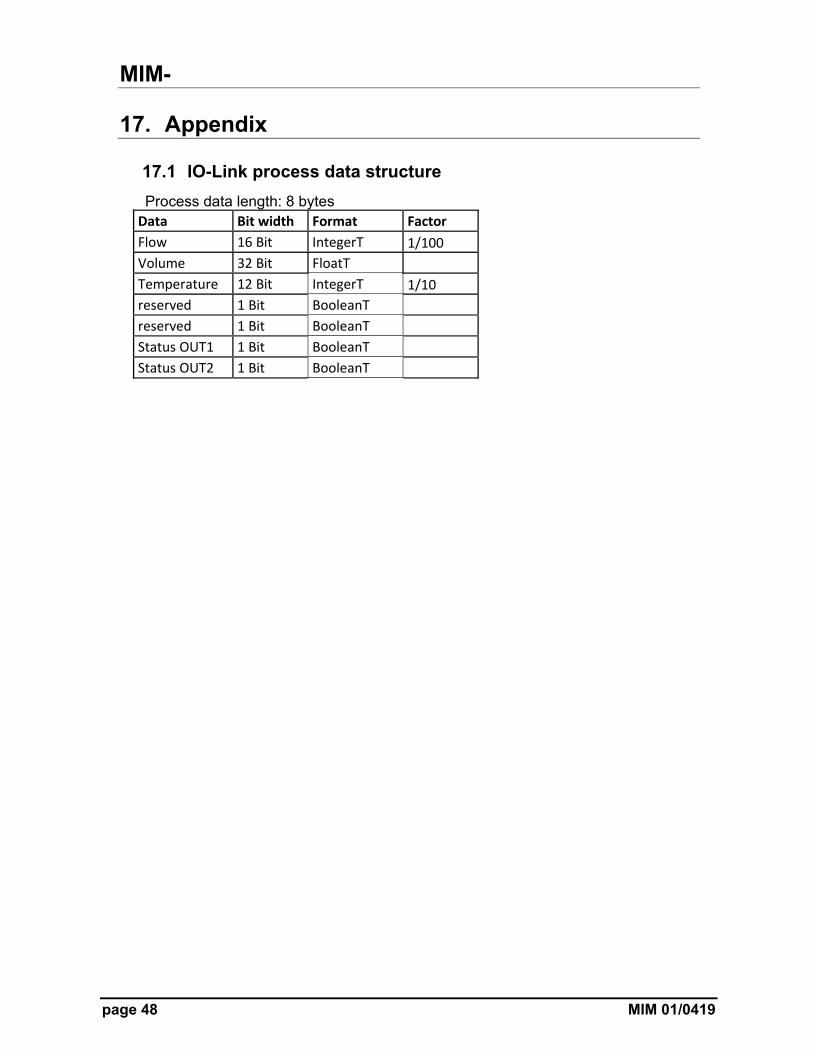
17. Appendix
17.1 IO-Link process data structure
Process data length: 8 bytes Data Bit width Format Factor
Flow 16 Bit IntegerT 1/100
Volume 32 Bit FloatT
Temperature 12 Bit IntegerT 1/10
reserved 1 Bit BooleanT
reserved 1 Bit BooleanT
Status OUT1 1 Bit BooleanT
Status OUT2 1 Bit BooleanT

MIM-
MIM 01/0419 page 49
17.2 IO-Link diagnosis information
Event Code hex
Name Device Status
Type Definition
0x7710 Short Circuit Error check installation
0x8C10 Process Variable Range Overrun Warning process data uncertain
0x8C20 Measurement Range Overrun Error check application
0x8C30 Process Variable Range Underrun Warning process data uncertain
0x1838 1. Test Event For Protocol Testing Error first test event
0x1839 2. Test Event For Protocol Testing Error secont test event
0x183A Flow MRE Overrun Warning flow measuring range overrun
0x183B Flow MRS Underrun Warning flow measuring range underrun
0x183C Flow Overflow Overrun 2 Warning flow overflow range overrun
0x183D Flow Underflow Underrun 2 Warning flow underflow range underrun
0x183E Flow Cutoff Out Warning out of flow cutoff range
0x183F Temperature MRE Overrun Warning temperature measuring range overrun
0x1840 Temperature MRS Underrun Warning temperature measuring range underrun
0x1841 Temperature Overflow Overrun 2 Warning temperature overflow range overrun
0x1842 Temperature Underflow Underrun 2 Warning temperature underflow range underrun
0x1843 NVM Error 4 Error non‐volatile memory is corrupt
0x1844 Subslave Lost Error communication to subslave interrupted
0x1845 Subslave Not Found 4 Error communication to subslave couldn`t be established
MIM-
page 50 MIM 01/0419
Event Code hex
Name Device Status
Type Definition
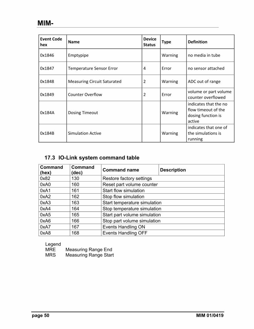
0x1846 Emptypipe Warning no media in tube
0x1847 Temperature Sensor Error 4 Error no sensor attached
0x1848 Measuring Circuit Saturated 2 Warning ADC out of range
0x1849 Counter Overflow 2 Error volume or part volume counter overflowed
0x184A Dosing Timeout Warning
indicates that the no flow timeout of the dosing function is active
0x184B Simulation Active Warning indicates that one of the simulations is running
17.3 IO-Link system command table
Command (hex)
Command (dec)
Command name Description
0x82 130 Restore factory settings 0xA0 160 Reset part volume counter 0xA1 161 Start flow simulation 0xA2 162 Stop flow simulation 0xA3 163 Start temperature simulation 0xA4 164 Stop temperature simulation 0xA5 165 Start part volume simulation 0xA6 166 Stop part volume simulation 0xA7 167 Events Handling ON 0xA8 168 Events Handling OFF
Legend MRE Measuring Range End MRS Measuring Range Start
MIM-
MIM 01/0419 page 51
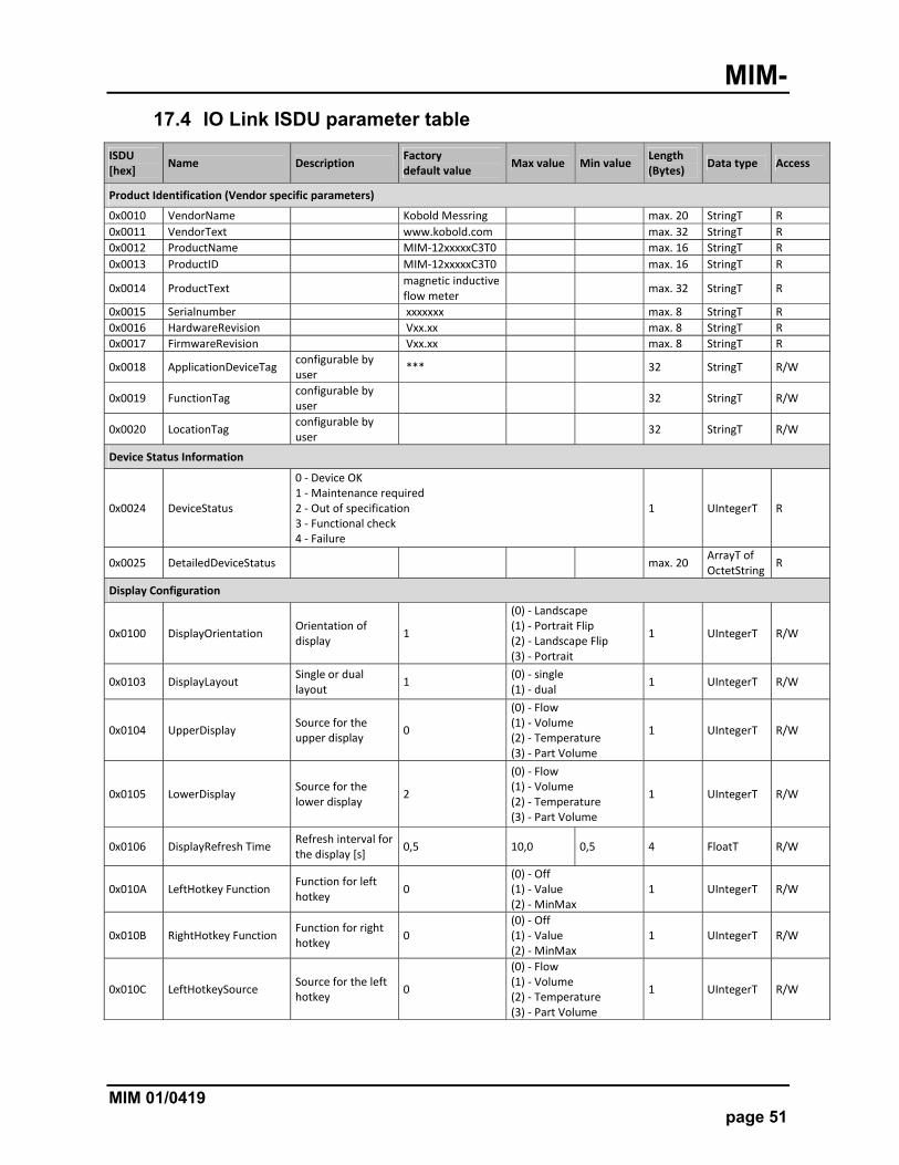
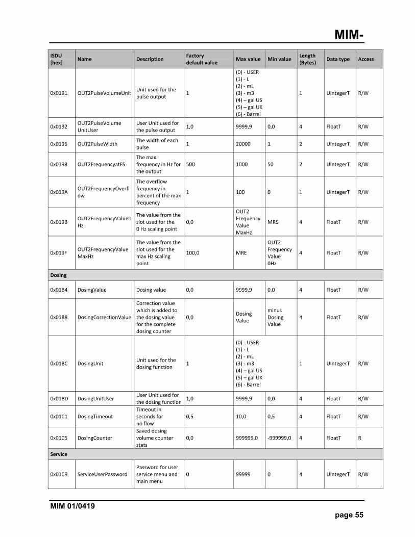
17.4 IO Link ISDU parameter table
ISDU [hex]
Name Description Factory default value
Max value Min value Length (Bytes)
Data type Access
Product Identification (Vendor specific parameters)
0x0010 VendorName Kobold Messring max. 20 StringT R
0x0011 VendorText www.kobold.com max. 32 StringT R
0x0012 ProductName MIM‐12xxxxxC3T0 max. 16 StringT R
0x0013 ProductID MIM‐12xxxxxC3T0 max. 16 StringT R
0x0014 ProductText magnetic inductive flow meter
max. 32 StringT R
0x0015 Serialnumber xxxxxxx max. 8 StringT R
0x0016 HardwareRevision Vxx.xx max. 8 StringT R
0x0017 FirmwareRevision Vxx.xx max. 8 StringT R
0x0018 ApplicationDeviceTag configurable by user
*** 32 StringT R/W
0x0019 FunctionTag configurable by user
32 StringT R/W
0x0020 LocationTag configurable by user
32 StringT R/W
Device Status Information
0x0024 DeviceStatus
0 ‐ Device OK 1 ‐ Maintenance required 2 ‐ Out of specification 3 ‐ Functional check 4 ‐ Failure
1 UIntegerT R
0x0025 DetailedDeviceStatus max. 20 ArrayT of OctetString
R
Display Configuration
0x0100 DisplayOrientation Orientation of display
1
(0) ‐ Landscape (1) ‐ Portrait Flip (2) ‐ Landscape Flip (3) ‐ Portrait
1 UIntegerT R/W
0x0103 DisplayLayout Single or dual layout
1 (0) ‐ single (1) ‐ dual
1 UIntegerT R/W
0x0104 UpperDisplay Source for the upper display
0
(0) ‐ Flow (1) ‐ Volume (2) ‐ Temperature (3) ‐ Part Volume
1 UIntegerT R/W
0x0105 LowerDisplay Source for the lower display
2
(0) ‐ Flow (1) ‐ Volume (2) ‐ Temperature (3) ‐ Part Volume
1 UIntegerT R/W
0x0106 DisplayRefresh Time Refresh interval for the display [s]
0,5 10,0 0,5 4 FloatT R/W
0x010A LeftHotkey Function Function for left hotkey
0 (0) ‐ Off (1) ‐ Value (2) ‐ MinMax
1 UIntegerT R/W
0x010B RightHotkey Function Function for right hotkey
0 (0) ‐ Off (1) ‐ Value (2) ‐ MinMax
1 UIntegerT R/W
0x010C LeftHotkeySource Source for the left hotkey
0
(0) ‐ Flow (1) ‐ Volume (2) ‐ Temperature (3) ‐ Part Volume
1 UIntegerT R/W

MIM-
page 52 MIM 01/0419
ISDU [hex]
Name Description Factory default value
Max value Min value Length (Bytes)
Data type Access
0x010D RightHotkeySource Source for the right hotkey
0
(0) ‐ Flow (1) ‐ Volume (2) ‐ Temperature (3) ‐ Part Volume
1 UIntegerT R/W
0x010E SensitivityOptical Keys Sensitivity for the optical keys
0 (0) ‐ low (1) ‐ middle (2) ‐ high
1 UIntegerT R/W
0x010F AutomaticMenu Leave
Automatic menu leave if the timeout [s] is hit. 0 = timeout not active
0 60 0 1 UIntegerT R/W
Output 1
0x0112 OUT1Alarm Function Limit or window function for the alarm output
0 (0) ‐ Limit (1) ‐ Window
1 UIntegerT R/W
0x0113 OUT1Alarm outputType
Alarm output NPN, PNP or Pushpull
0 (0) ‐ NPN (1) ‐ PNP (2) ‐ PushPull
1 UIntegerT R/W
0x0114 OUT1AlarmSwitch Function
Alarm output normally opened or closed
0 (0) ‐ normally opened (1) ‐ normally closed
1 UIntegerT R/W
0x0115 OUT1Alarm Threshold Threshold for the alarm output
1,0 MRE MRS 4 FloatT R/W
0x0119 OUT1AlarmLower Threshold
Threshold for the alarm output used by the window function
1,0 OUT1AlarmThreshold
MRS 4 FloatT R/W
0x011D OUT1AlarmHysteresis Switching hysteresis for the alarm output
1,0 9999,0 ‐9999,0 4 FloatT R/W
0x0121 OUT1Alarm SuppressionFactor
How many times the threshold must be hit in order to switch the alarm output
0 60 0 1 UIntegerT R/W
0x0122 OUT1AnalogNamur Standard
If enabled (1) the analog output conforms with the NAMUR Standard NE42. If disabled (0) the analog output stays in his equivalent range (e.g. 4‐20 mA)
1 (0) ‐ NAMUR disabled (1) ‐ NAMUR enabled
1 UIntegerT R/W
0x0123 OUT1AnalogValue0mA The value from the slot used for the 0mA scaling point
0,0
OUT1 Analog Value 20mA
MRS 4 FloatT R/W
0x0127 OUT1AnalogValue4mA The value from the slot used for the 4 mA scaling point
0,0
OUT1 Analog Value 20mA
MRS 4 FloatT R/W
0x012B OUT1AnalogValue 20mA
The value from the slot used for the 20 mA scaling point
100,0 MRE
OUT1 Analog Value 0mA
4 FloatT R/W
MIM-
MIM 01/0419 page 53
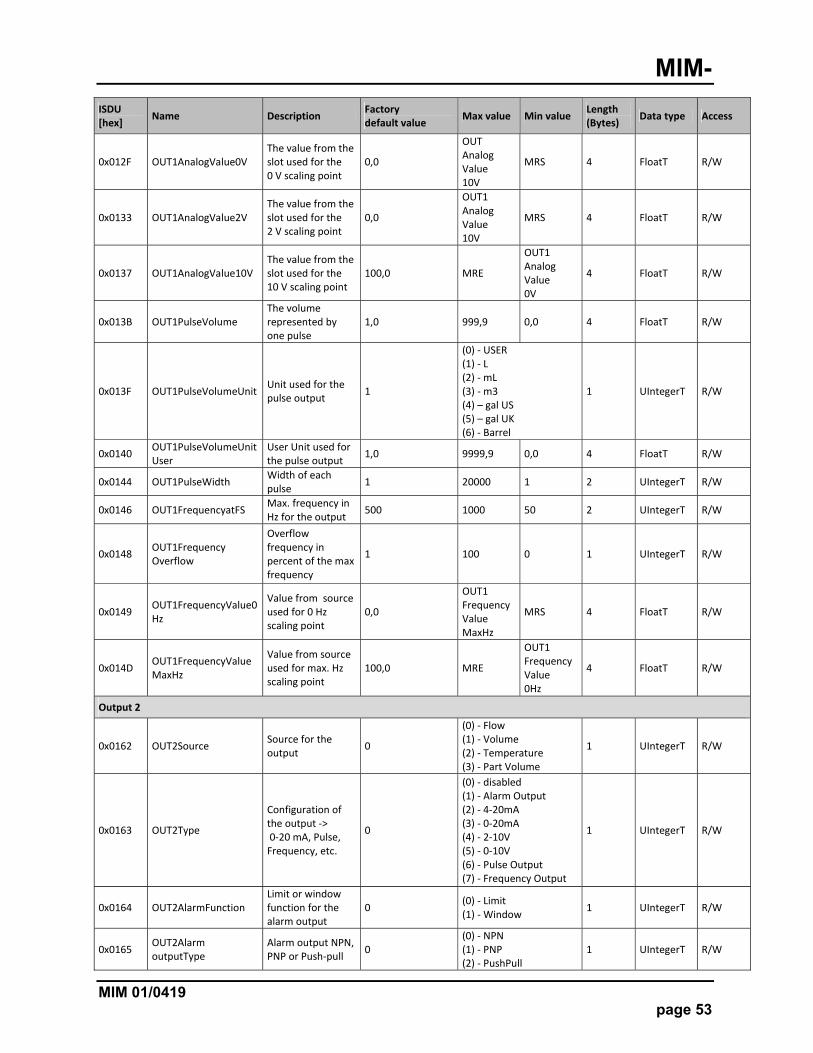
ISDU [hex]
Name Description Factory default value
Max value Min value Length (Bytes)
Data type Access
0x012F OUT1AnalogValue0V The value from the slot used for the 0 V scaling point
0,0
OUT Analog Value 10V
MRS 4 FloatT R/W
0x0133 OUT1AnalogValue2V The value from the slot used for the 2 V scaling point
0,0
OUT1 Analog Value 10V
MRS 4 FloatT R/W
0x0137 OUT1AnalogValue10V The value from the slot used for the 10 V scaling point
100,0 MRE
OUT1 Analog Value 0V
4 FloatT R/W
0x013B OUT1PulseVolume The volume represented by one pulse
1,0 999,9 0,0 4 FloatT R/W
0x013F OUT1PulseVolumeUnit Unit used for the pulse output
1
(0) ‐ USER (1) ‐ L (2) ‐ mL (3) ‐ m3 (4) – gal US (5) – gal UK (6) ‐ Barrel
1 UIntegerT R/W
0x0140 OUT1PulseVolumeUnitUser
User Unit used for the pulse output
1,0 9999,9 0,0 4 FloatT R/W
0x0144 OUT1PulseWidth Width of each pulse
1 20000 1 2 UIntegerT R/W
0x0146 OUT1FrequencyatFS Max. frequency in Hz for the output
500 1000 50 2 UIntegerT R/W
0x0148 OUT1Frequency Overflow
Overflow frequency in percent of the max frequency
1 100 0 1 UIntegerT R/W
0x0149 OUT1FrequencyValue0Hz
Value from source used for 0 Hz scaling point
0,0
OUT1 FrequencyValue MaxHz
MRS 4 FloatT R/W
0x014D OUT1FrequencyValueMaxHz
Value from source used for max. Hz scaling point
100,0 MRE
OUT1 FrequencyValue 0Hz
4 FloatT R/W
Output 2
0x0162 OUT2Source Source for the output
0
(0) ‐ Flow (1) ‐ Volume (2) ‐ Temperature (3) ‐ Part Volume
1 UIntegerT R/W
0x0163 OUT2Type
Configuration of the output ‐> 0‐20 mA, Pulse, Frequency, etc.
0
(0) ‐ disabled (1) ‐ Alarm Output (2) ‐ 4‐20mA (3) ‐ 0‐20mA (4) ‐ 2‐10V (5) ‐ 0‐10V (6) ‐ Pulse Output (7) ‐ Frequency Output
1 UIntegerT R/W
0x0164 OUT2AlarmFunction Limit or window function for the alarm output
0 (0) ‐ Limit (1) ‐ Window
1 UIntegerT R/W
0x0165 OUT2Alarm outputType
Alarm output NPN, PNP or Push‐pull
0 (0) ‐ NPN (1) ‐ PNP (2) ‐ PushPull
1 UIntegerT R/W
MIM-
page 54 MIM 01/0419
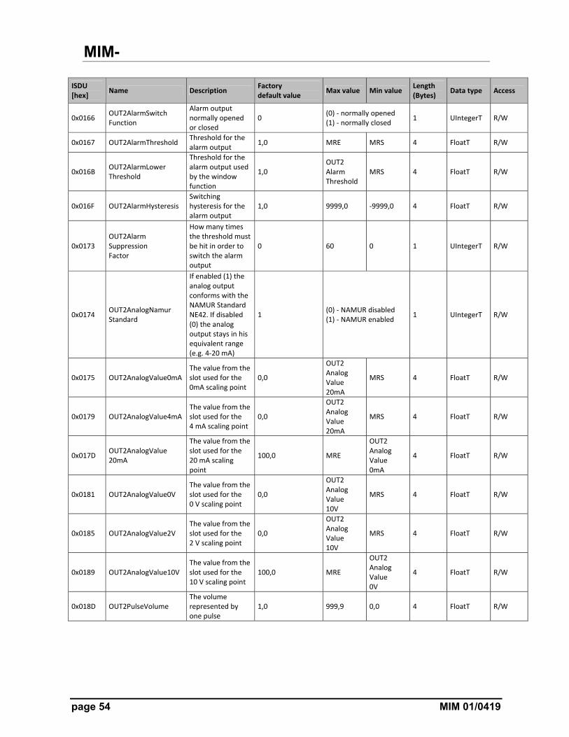
ISDU [hex]
Name Description Factory default value
Max value Min value Length (Bytes)
Data type Access
0x0166 OUT2AlarmSwitch Function
Alarm output normally opened or closed
0 (0) ‐ normally opened (1) ‐ normally closed
1 UIntegerT R/W
0x0167 OUT2AlarmThreshold Threshold for the alarm output
1,0 MRE MRS 4 FloatT R/W
0x016B OUT2AlarmLower Threshold
Threshold for the alarm output used by the window function
1,0 OUT2 Alarm Threshold
MRS 4 FloatT R/W
0x016F OUT2AlarmHysteresis Switching hysteresis for the alarm output
1,0 9999,0 ‐9999,0 4 FloatT R/W
0x0173 OUT2Alarm Suppression Factor
How many times the threshold must be hit in order to switch the alarm output
0 60 0 1 UIntegerT R/W
0x0174 OUT2AnalogNamur Standard
If enabled (1) the analog output conforms with the NAMUR Standard NE42. If disabled (0) the analog output stays in his equivalent range (e.g. 4‐20 mA)
1 (0) ‐ NAMUR disabled (1) ‐ NAMUR enabled
1 UIntegerT R/W
0x0175 OUT2AnalogValue0mA The value from the slot used for the 0mA scaling point
0,0
OUT2 Analog Value 20mA
MRS 4 FloatT R/W
0x0179 OUT2AnalogValue4mA The value from the slot used for the 4 mA scaling point
0,0
OUT2 Analog Value 20mA
MRS 4 FloatT R/W
0x017D OUT2AnalogValue 20mA
The value from the slot used for the 20 mA scaling point
100,0 MRE
OUT2 Analog Value 0mA
4 FloatT R/W
0x0181 OUT2AnalogValue0V The value from the slot used for the 0 V scaling point
0,0
OUT2 Analog Value 10V
MRS 4 FloatT R/W
0x0185 OUT2AnalogValue2V The value from the slot used for the 2 V scaling point
0,0
OUT2 Analog Value 10V
MRS 4 FloatT R/W
0x0189 OUT2AnalogValue10V The value from the slot used for the 10 V scaling point
100,0 MRE
OUT2 Analog Value 0V
4 FloatT R/W
0x018D OUT2PulseVolume The volume represented by one pulse
1,0 999,9 0,0 4 FloatT R/W
MIM-
MIM 01/0419 page 55
ISDU [hex]
Name Description Factory default value
Max value Min value Length (Bytes)
Data type Access
0x0191 OUT2PulseVolumeUnit Unit used for the pulse output
1
(0) ‐ USER (1) ‐ L (2) ‐ mL (3) ‐ m3 (4) – gal US (5) – gal UK (6) ‐ Barrel
1 UIntegerT R/W
0x0192 OUT2PulseVolume UnitUser
User Unit used for the pulse output
1,0 9999,9 0,0 4 FloatT R/W
0x0196 OUT2PulseWidth The width of each pulse
1 20000 1 2 UIntegerT R/W
0x0198 OUT2FrequencyatFS The max. frequency in Hz for the output
500 1000 50 2 UIntegerT R/W
0x019A OUT2FrequencyOverflow
The overflow frequency in percent of the max frequency
1 100 0 1 UIntegerT R/W
0x019B OUT2FrequencyValue0Hz
The value from the slot used for the 0 Hz scaling point
0,0
OUT2 Frequency Value MaxHz
MRS 4 FloatT R/W
0x019F OUT2FrequencyValueMaxHz
The value from the slot used for the max Hz scaling point
100,0 MRE
OUT2 FrequencyValue 0Hz
4 FloatT R/W
Dosing
0x01B4 DosingValue Dosing value 0,0 9999,9 0,0 4 FloatT R/W
0x01B8 DosingCorrectionValue
Correction value which is added to the dosing value for the complete dosing counter
0,0 Dosing Value
minus Dosing Value
4 FloatT R/W
0x01BC DosingUnit Unit used for the dosing function
1
(0) ‐ USER (1) ‐ L (2) ‐ mL (3) ‐ m3 (4) – gal US (5) – gal UK (6) ‐ Barrel
1 UIntegerT R/W
0x01BD DosingUnitUser User Unit used for the dosing function
1,0 9999,9 0,0 4 FloatT R/W
0x01C1 DosingTimeout Timeout in seconds for no flow
0,5 10,0 0,5 4 FloatT R/W
0x01C5 DosingCounter Saved dosing volume counter stats
0,0 999999,0 ‐999999,0 4 FloatT R
Service
0x01C9 ServiceUserPassword Password for user service menu and main menu
0 99999 0 4 UIntegerT R/W
MIM-
page 56 MIM 01/0419
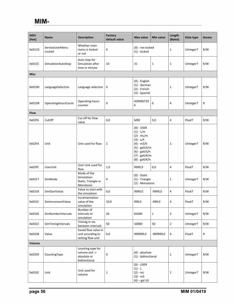
ISDU [hex]
Name Description Factory default value
Max value Min value Length (Bytes)
Data type Access
0x01CD ServiceUserMenu Locked
Whether main menu is locked or not
0 (0) ‐ not locked (1) ‐ locked
1 UIntegerT R/W
0x01CE SimulationAutoStop Auto stop for Simulation after time in minute
10 31 1 1 UIntegerT R/W
Misc
0x01D0 LanguageSelection Language selection 0
(0) ‐ English (1) ‐ German (2) ‐ French (3) ‐ Spanish
1 UIntegerT R/W
0x01D8 OperatingHoursCount Operating hours counter
0 4294967296
0 4 UIntegerT R
Flow
0x02F6 CutOff Cut off for flow value
0,0 MRE 0,0 4 FloatT R/W
0x02FA Unit Unit used for flow 1
(0) ‐ USER (1) ‐ L/m (2) ‐ mL/m (3) ‐ L/h (4) ‐ m3/h (5) ‐ galUS/m (6) ‐ galUS/h (7) ‐ galUK/m (8) ‐ galUK/h
1 UIntegerT R/W
0x02FE UserUnit User Unit used for flow
1,0 9999,9 0,0 4 FloatT R/W
0x0317 SimMode
Mode of the Simulation: Static, Triangle or Monotonic
0 (0) ‐ Static (1) ‐ Triangle (2) ‐ Monotonic
1 UIntegerT R/W
0x0318 SimStartValue Value to start with the simulation
0,0 9999,0 ‐9999,0 4 FloatT R/W
0x031C SimIncrementValue Incrementation value of the simulation
10,0 999,0 ‐999,0 4 FloatT R/W
0x0320 SimNumberIntervals Number of intervals to simulation
20 65000 1 2 UIntegerT R/W
0x0322 SimTimingIntervals Timinig in ms between intervals
50 50000 50 2 UIntegerT R/W
0x0328 Value Saved flow value in unit according to setting flow unit
0,0 999999,0 ‐999999,0 4 FloatT R
Volume
0x0359 CountingType
counting type for volume slot ‐> absolute or bidirectional
0 (0) ‐ absolute (1) ‐ bidirectional
1 UIntegerT R/W
0x035E Unit Unit used for volume
1
(0) ‐ USER (1) ‐ L (2) ‐ mL (3) ‐ m3 (4) – gal US
1 UIntegerT R/W
MIM-
MIM 01/0419 page 57
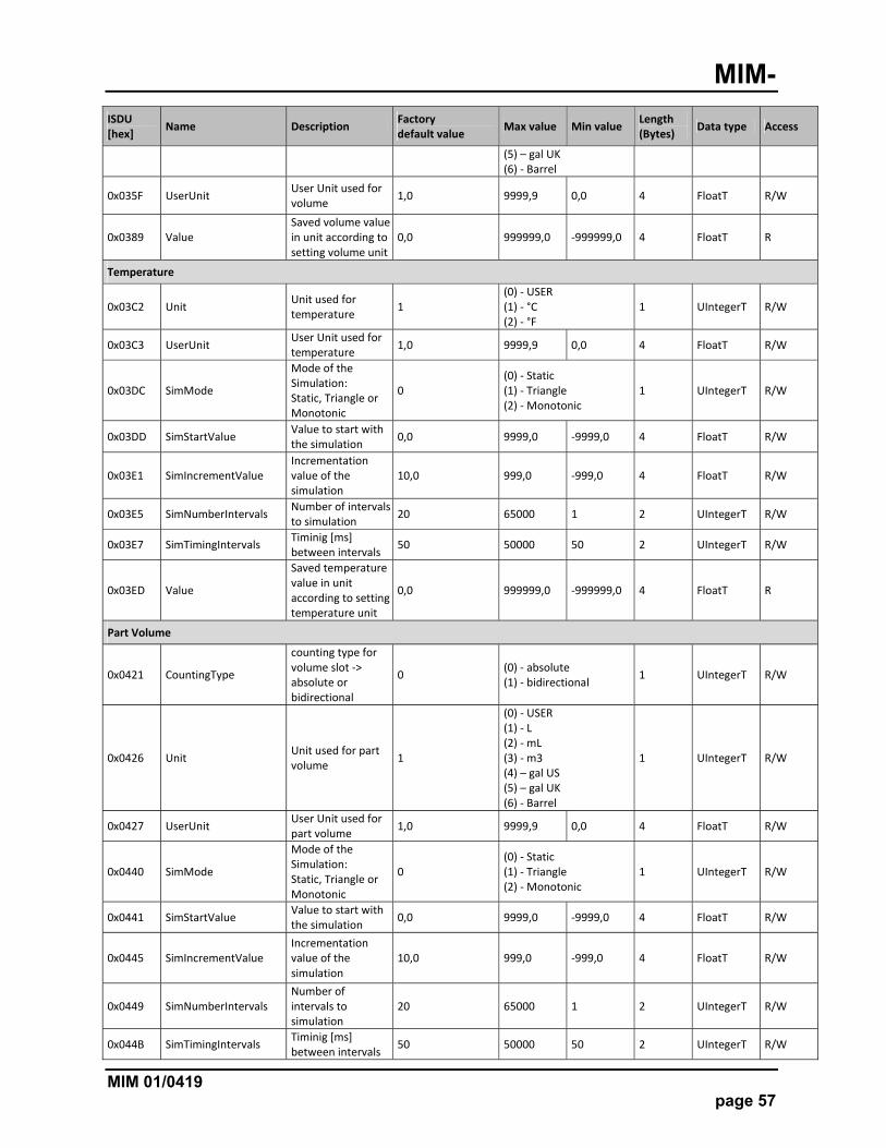
ISDU [hex]
Name Description Factory default value
Max value Min value Length (Bytes)
Data type Access
(5) – gal UK (6) ‐ Barrel
0x035F UserUnit User Unit used for volume
1,0 9999,9 0,0 4 FloatT R/W
0x0389 Value Saved volume value in unit according to setting volume unit
0,0 999999,0 ‐999999,0 4 FloatT R
Temperature
0x03C2 Unit Unit used for temperature
1 (0) ‐ USER (1) ‐ °C (2) ‐ °F
1 UIntegerT R/W
0x03C3 UserUnit User Unit used for temperature
1,0 9999,9 0,0 4 FloatT R/W
0x03DC SimMode
Mode of the Simulation: Static, Triangle or Monotonic
0 (0) ‐ Static (1) ‐ Triangle (2) ‐ Monotonic
1 UIntegerT R/W
0x03DD SimStartValue Value to start with the simulation
0,0 9999,0 ‐9999,0 4 FloatT R/W
0x03E1 SimIncrementValue Incrementation value of the simulation
10,0 999,0 ‐999,0 4 FloatT R/W
0x03E5 SimNumberIntervals Number of intervals to simulation
20 65000 1 2 UIntegerT R/W
0x03E7 SimTimingIntervals Timinig [ms] between intervals
50 50000 50 2 UIntegerT R/W
0x03ED Value
Saved temperature value in unit according to setting temperature unit
0,0 999999,0 ‐999999,0 4 FloatT R
Part Volume
0x0421 CountingType
counting type for volume slot ‐> absolute or bidirectional
0 (0) ‐ absolute (1) ‐ bidirectional
1 UIntegerT R/W
0x0426 Unit Unit used for part volume
1
(0) ‐ USER (1) ‐ L (2) ‐ mL (3) ‐ m3 (4) – gal US (5) – gal UK (6) ‐ Barrel
1 UIntegerT R/W
0x0427 UserUnit User Unit used for part volume
1,0 9999,9 0,0 4 FloatT R/W
0x0440 SimMode
Mode of the Simulation: Static, Triangle or Monotonic
0 (0) ‐ Static (1) ‐ Triangle (2) ‐ Monotonic
1 UIntegerT R/W
0x0441 SimStartValue Value to start with the simulation
0,0 9999,0 ‐9999,0 4 FloatT R/W
0x0445 SimIncrementValue Incrementation value of the simulation
10,0 999,0 ‐999,0 4 FloatT R/W
0x0449 SimNumberIntervals Number of intervals to simulation
20 65000 1 2 UIntegerT R/W
0x044B SimTimingIntervals Timinig [ms] between intervals
50 50000 50 2 UIntegerT R/W
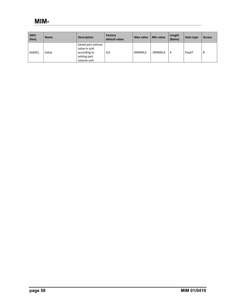
MIM-
page 58 MIM 01/0419
ISDU [hex]
Name Description Factory default value
Max value Min value Length (Bytes)
Data type Access
0x0451 Value
Saved part volume value in unit according to setting part volume unit
0,0 999999,0 ‐999999,0 4 FloatT R
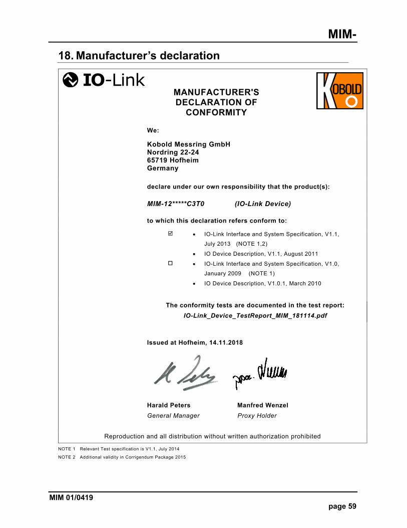
MIM-
MIM 01/0419 page 59
18. Manufacturer’s declaration
NOTE 1 Relevant Test specification is V1.1, July 2014
NOTE 2 Additional validity in Corrigendum Package 2015
MANUFACTURER'S DECLARATION OF
CONFORMITY
We:
Kobold Messring GmbH Nordring 22-24 65719 Hofheim Germany
declare under our own responsibility that the product(s):
MIM-12*****C3T0 (IO-Link Device)
to which this declaration refers conform to:
IO-Link Interface and System Specification, V1.1,
July 2013 (NOTE 1,2)
IO Device Description, V1.1, August 2011
IO-Link Interface and System Specification, V1.0,
January 2009 (NOTE 1)
IO Device Description, V1.0.1, March 2010
The conformity tests are documented in the test report:
IO-Link_Device_TestReport_MIM_181114.pdf
Issued at Hofheim, 14.11.2018
Harald Peters Manfred Wenzel
General Manager Proxy Holder
Reproduction and all distribution without written authorization prohibited
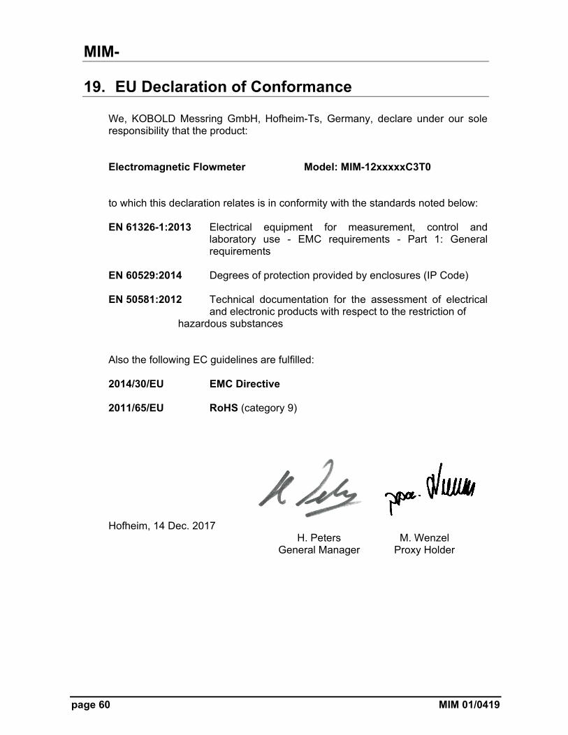
MIM-
page 60 MIM 01/0419
19. EU Declaration of Conformance
We, KOBOLD Messring GmbH, Hofheim-Ts, Germany, declare under our sole responsibility that the product: Electromagnetic Flowmeter Model: MIM-12xxxxxC3T0 to which this declaration relates is in conformity with the standards noted below: EN 61326-1:2013 Electrical equipment for measurement, control and
laboratory use - EMC requirements - Part 1: General requirements
EN 60529:2014 Degrees of protection provided by enclosures (IP Code) EN 50581:2012 Technical documentation for the assessment of electrical and electronic products with respect to the restriction of hazardous substances Also the following EC guidelines are fulfilled: 2014/30/EU EMC Directive 2011/65/EU RoHS (category 9)
Hofheim, 14 Dec. 2017 H. Peters M. Wenzel General Manager Proxy Holder