Embed Size (px)
Citation preview

4
Please record the following data for fi le reference
Tag Number(s): _____________________________________
Model Number: ____________________________________
Serial Number: _____________________________________
Installation Date: ____________________________________
Installation Location: __________________________________________________________________________________
MILROYAL® B DRIVE
339-0066-000ISSUED 01/2012
This manual supersedes the following manual: 339-0066-000 Dated 02/01/2000
INSTALLATION, OPERATION, AND MAINTENANCE MANUAL
PRECAUTIONS The following precautions should be taken when working with metering pumps. Please read this section carefully prior to installation. Protective Clothing
!
ALWAYS wear protective clothing, face shield, safety glasses and gloves when working on or near your metering pump. Additional precautions should be taken depending on the solution being pumped. Refer to Material Safety Data Sheets for the solution being pumped.
Hearing Protection
! It is re commended that h earing p rotection be used if the pu mp is in an environment where the time -weighted average sound level (TWA) of 85 decibels is exceeded. (as measured on the A scale -- slo w response)
Electrical Safety
!
• Remove power and ensure that it remains off while maintaining pump. • DO NOT FORGET TO CONNECT THE PUMP TO EARTH/GROUND • Electric protection of the motor (Thermal protection or by means of fuses) is to correspond to
the rated current indicated on the motor data plate.
Liquid Compatibility
!
Verify if the material s of construction of the wetted components of your pump are recommended for the solution (chemical) to be pumped.
Pumps Water “Primed”
!
All pumps are tested with water at the factory. If your process solution is not compatible with water, flush the Pump Head Assembly with an appropriate solution before introducing the process solution
Plumbing and Electrical Connections
! Always adhere to your local plumbing and electrical codes.
Line Depressurization
!
To reduce the risk of che mical contact during disassembly or maintenance, the su ction and discharge lines should be depressurized before servicing.
Over Pressure Protection
! To ensure safe operation of the system it is recommended that some type of safety/pressure-relief valve be installed to protect the piping and other system components from damage due to over-pressure.
Lifting
! This manual should be used as a guide only - Follow your company’s recommended lifting procedures. It is not intended to replace or take precedence over recommendations, policies and procedures judged as safe due to the local environment than what is contained herein. ! Use lifting equipment that is rated for the weight of the equipment to be lifted.
i

i
TABLE OF CONTENTS
SECTION 1 - GENERAL DESCRIPTION . . . . . . . . . . . . . . . . . . . . . . . . . . . . . . . . . . . . . . . . . . . . . . . . . . . . . . . . 1
1.1 INTRODUCTION . . . . . . . . . . . . . . . . . . . . . . . . . . . . . . . . . . . . . . . . . . . . . . . . . . . . . . . . . . . . . . . . . . . . 1
1.2 MODEL CODE / PUMP IDENTIFICATION . . . . . . . . . . . . . . . . . . . . . . . . . . . . . . . . . . . . . . . . . . . . . . . . .1
1.3 PRINCIPLE OF OPERATION . . . . . . . . . . . . . . . . . . . . . . . . . . . . . . . . . . . . . . . . . . . . . . . . . . . . . . . . . . 1
1.4 SAFETY PRECAUTIONS . . . . . . . . . . . . . . . . . . . . . . . . . . . . . . . . . . . . . . . . . . . . . . . . . . . . . . . . . . . . . .2
1.5 SPECIFICATIONS . . . . . . . . . . . . . . . . . . . . . . . . . . . . . . . . . . . . . . . . . . . . . . . . . . . . . . . . . . . . . . . . . . . 2
SECTION 2 - INSTALLATION . . . . . . . . . . . . . . . . . . . . . . . . . . . . . . . . . . . . . . . . . . . . . . . . . . . . . . . . . . . . . . . . 3
2.1 UNPACKING/INSPECTION. . . . . . . . . . . . . . . . . . . . . . . . . . . . . . . . . . . . . . . . . . . . . . . . . . . . . . . . . . . . 3
2.2 STORAGE . . . . . . . . . . . . . . . . . . . . . . . . . . . . . . . . . . . . . . . . . . . . . . . . . . . . . . . . . . . . . . . . . . . . . . . . . .3
2.3 SAFETY PRECAUTIONS . . . . . . . . . . . . . . . . . . . . . . . . . . . . . . . . . . . . . . . . . . . . . . . . . . . . . . . . . . . . . 4
2.4 PUMP MOUNTING/LOCATION . . . . . . . . . . . . . . . . . . . . . . . . . . . . . . . . . . . . . . . . . . . . . . . . . . . . . . . . . .4
2.5 PIPING. . . . . . . . . . . . . . . . . . . . . . . . . . . . . . . . . . . . . . . . . . . . . . . . . . . . . . . . . . . . . . . . . . . . . . . . . . . . 4
2.5.1 General . . . . . . . . . . . . . . . . . . . . . . . . . . . . . . . . . . . . . . . . . . . . . . . . . . . . . . . . . . . . . . . . . . . . . . . .4
2.5.2 Suction Piping . . . . . . . . . . . . . . . . . . . . . . . . . . . . . . . . . . . . . . . . . . . . . . . . . . . . . . . . . . . . . . . . . . .5
2.5.3 Discharge Piping . . . . . . . . . . . . . . . . . . . . . . . . . . . . . . . . . . . . . . . . . . . . . . . . . . . . . . . . . . . . . . . . .5
2.6 VENTED RISERS . . . . . . . . . . . . . . . . . . . . . . . . . . . . . . . . . . . . . . . . . . . . . . . . . . . . . . . . . . . . . . . . . . . 5
2.7 PULSATION DAMPENERS . . . . . . . . . . . . . . . . . . . . . . . . . . . . . . . . . . . . . . . . . . . . . . . . . . . . . . . . . . . . 6
2.8 BACK PRESSURE VALVES . . . . . . . . . . . . . . . . . . . . . . . . . . . . . . . . . . . . . . . . . . . . . . . . . . . . . . . . . . . 6
2.9 SAFETY VALVES. . . . . . . . . . . . . . . . . . . . . . . . . . . . . . . . . . . . . . . . . . . . . . . . . . . . . . . . . . . . . . . . . . . . 6
2.10 CHECK VALVES . . . . . . . . . . . . . . . . . . . . . . . . . . . . . . . . . . . . . . . . . . . . . . . . . . . . . . . . . . . . . . . . . . . 6
2.11 SHUT-OFF VALVES. . . . . . . . . . . . . . . . . . . . . . . . . . . . . . . . . . . . . . . . . . . . . . . . . . . . . . . . . . . . . . . . . 6
2.12 SERVICE CONNECTIONS . . . . . . . . . . . . . . . . . . . . . . . . . . . . . . . . . . . . . . . . . . . . . . . . . . . . . . . . . . . 7
2.12.1 Pump Drive . . . . . . . . . . . . . . . . . . . . . . . . . . . . . . . . . . . . . . . . . . . . . . . . . . . . . . . . . . . . . . . . . . . .7
2.12.2 Stuffing Box . . . . . . . . . . . . . . . . . . . . . . . . . . . . . . . . . . . . . . . . . . . . . . . . . . . . . . . . . . . . . . . . . . . .7
2.12.3 Drains . . . . . . . . . . . . . . . . . . . . . . . . . . . . . . . . . . . . . . . . . . . . . . . . . . . . . . . . . . . . . . . . . . . . . . . .8
2.12.4 Auxiliary (Accessory) Equipment. . . . . . . . . . . . . . . . . . . . . . . . . . . . . . . . . . . . . . . . . . . . . . . . . . . .8
SECTION 3 - OPERATION . . . . . . . . . . . . . . . . . . . . . . . . . . . . . . . . . . . . . . . . . . . . . . . . . . . . . . . . . . . . . . . . . . . .9
3.1 INITIAL START-UP . . . . . . . . . . . . . . . . . . . . . . . . . . . . . . . . . . . . . . . . . . . . . . . . . . . . . . . . . . . . . . . . . . .9
3.2 OIL SPECIFICATIONS . . . . . . . . . . . . . . . . . . . . . . . . . . . . . . . . . . . . . . . . . . . . . . . . . . . . . . . . . . . . . . . .9
3.3 INITIAL ADJUSTMENTS . . . . . . . . . . . . . . . . . . . . . . . . . . . . . . . . . . . . . . . . . . . . . . . . . . . . . . . . . . . . . . .9
3.3.1 Micrometer Capacity Control . . . . . . . . . . . . . . . . . . . . . . . . . . . . . . . . . . . . . . . . . . . . . . . . . . . . . . . .9

ii
3.3.2 Electronic Capacity Control . . . . . . . . . . . . . . . . . . . . . . . . . . . . . . . . . . . . . . . . . . . . . . . . . . . . . . . . 9
3.3.3 Pneumatic Capacity Control . . . . . . . . . . . . . . . . . . . . . . . . . . . . . . . . . . . . . . . . . . . . . . . . . . . . . . . . 9
3.3.4 Speed Capacity Control . . . . . . . . . . . . . . . . . . . . . . . . . . . . . . . . . . . . . . . . . . . . . . . . . . . . . . . . . . . 9
3.3.5 Capacity Calibration . . . . . . . . . . . . . . . . . . . . . . . . . . . . . . . . . . . . . . . . . . . . . . . . . . . . . . . . . . . . . . 9
3.4 FILLING PUMP SYSTEM . . . . . . . . . . . . . . . . . . . . . . . . . . . . . . . . . . . . . . . . . . . . . . . . . . . . . . . . . . . . . 10
3.5 PREVENTATIVE MAINTENANCE . . . . . . . . . . . . . . . . . . . . . . . . . . . . . . . . . . . . . . . . . . . . . . . . . . . . . . 10
3.5.1 Drive . . . . . . . . . . . . . . . . . . . . . . . . . . . . . . . . . . . . . . . . . . . . . . . . . . . . . . . . . . . . . . . . . . . . . . . . . 10
3.5.2 Motor . . . . . . . . . . . . . . . . . . . . . . . . . . . . . . . . . . . . . . . . . . . . . . . . . . . . . . . . . . . . . . . . . . . . . . . . 10
3.5.3 Check Valves . . . . . . . . . . . . . . . . . . . . . . . . . . . . . . . . . . . . . . . . . . . . . . . . . . . . . . . . . . . . . . . . . . 10
SECTION 4 - MAINTENANCE. . . . . . . . . . . . . . . . . . . . . . . . . . . . . . . . . . . . . . . . . . . . . . . . . . . . . . . . . . . . . . . . 11
4.1 SPARE PARTS . . . . . . . . . . . . . . . . . . . . . . . . . . . . . . . . . . . . . . . . . . . . . . . . . . . . . . . . . . . . . . . . . . . . 11
4.2 RETURNING UNITS TO THE FACTORY. . . . . . . . . . . . . . . . . . . . . . . . . . . . . . . . . . . . . . . . . . . . . . . . . 11
4.3 DISASSEMBLY. . . . . . . . . . . . . . . . . . . . . . . . . . . . . . . . . . . . . . . . . . . . . . . . . . . . . . . . . . . . . . . . . . . . . 11
4.3.1 Pump Drive. . . . . . . . . . . . . . . . . . . . . . . . . . . . . . . . . . . . . . . . . . . . . . . . . . . . . . . . . . . . . . . . . . . . 11
4.3.2 Crosshead Removal . . . . . . . . . . . . . . . . . . . . . . . . . . . . . . . . . . . . . . . . . . . . . . . . . . . . . . . . . . . . . 11
4.3.3 Gear Housing Removal . . . . . . . . . . . . . . . . . . . . . . . . . . . . . . . . . . . . . . . . . . . . . . . . . . . . . . . . . . 12
4.4 REASSEMBLY . . . . . . . . . . . . . . . . . . . . . . . . . . . . . . . . . . . . . . . . . . . . . . . . . . . . . . . . . . . . . . . . . . . . . 12
4.4.1 Pump Drive. . . . . . . . . . . . . . . . . . . . . . . . . . . . . . . . . . . . . . . . . . . . . . . . . . . . . . . . . . . . . . . . . . . . 12
4.4.2 Crosshead . . . . . . . . . . . . . . . . . . . . . . . . . . . . . . . . . . . . . . . . . . . . . . . . . . . . . . . . . . . . . . . . . . . . 13
4.4.3 Adjusting Gear Housing for Zero Stroke and Zero Micrometer Setting . . . . . . . . . . . . . . . . . . . . . . 13
SECTION 5 - TROUBLESHOOTING GUIDE. . . . . . . . . . . . . . . . . . . . . . . . . . . . . . . . . . . . . . . . . . . . . . . . . . . . . 15
SECTION 6 - PARTS . . . . . . . . . . . . . . . . . . . . . . . . . . . . . . . . . . . . . . . . . . . . . . . . . . . . . . . . . . . . . . . . . . . . . . . 17
6.1 GENERAL. . . . . . . . . . . . . . . . . . . . . . . . . . . . . . . . . . . . . . . . . . . . . . . . . . . . . . . . . . . . . . . . . . . . . . . . . 17
6.2 ILLUSTRATED PARTS LIST . . . . . . . . . . . . . . . . . . . . . . . . . . . . . . . . . . . . . . . . . . . . . . . . . . . . . . . . . . 17
6.3 BASIC PARTS LIST FOR MILROYAL B DRIVE ASSEMBLY DRAWING (102-2095-000). . . . . . . . . . . . 28
LIST OF ILLUSTRATIONS
FIGURE 1. Milroyal B Metering Pump . . . . . . . . . . . . . . . . . . . . . . . . . . . . . . . . . . . . . . . . . . . . . . . . . . . . . . . . IV
FIGURE 2. Capacity Adjustment . . . . . . . . . . . . . . . . . . . . . . . . . . . . . . . . . . . . . . . . . . . . . . . . . . . . . . . . . . . . . 1
FIGURE 3. Packed Plunger Liquid End (See manual 339-0065-000) . . . . . . . . . . . . . . . . . . . . . . . . . . . . . . . . . 2
FIGURE 4. HPD Liquid End (See manual 339-0014-000) . . . . . . . . . . . . . . . . . . . . . . . . . . . . . . . . . . . . . . . . . . 2
FIGURE 5. Float Box . . . . . . . . . . . . . . . . . . . . . . . . . . . . . . . . . . . . . . . . . . . . . . . . . . . . . . . . . . . . . . . . . . . . . . 5
FIGURE 6. Vented Riser . . . . . . . . . . . . . . . . . . . . . . . . . . . . . . . . . . . . . . . . . . . . . . . . . . . . . . . . . . . . . . . . . . . 6
FIGURE 7. Safety & Back Pressure Valves . . . . . . . . . . . . . . . . . . . . . . . . . . . . . . . . . . . . . . . . . . . . . . . . . . . . . 7

iii
FIGURE 8. Recommended Valve Locations . . . . . . . . . . . . . . . . . . . . . . . . . . . . . . . . . . . . . . . . . . . . . . . . . . . . .8
FIGURE 9. Pump Nameplate . . . . . . . . . . . . . . . . . . . . . . . . . . . . . . . . . . . . . . . . . . . . . . . . . . . . . . . . . . . . . . . 11
FIGURE 10. Milroyal B Drive Assembly Drawing (102-2095-000) Side View (Sheet 1 of 2) . . . . . . . . . . . . . . . .18
FIGURE 10. Milroyal B Drive Assembly Drawing (102-2095-000) Side View (Sheet 2 of 2) . . . . . . . . . . . . . . . .19

iv
FIGURE 1. Milroyal B Metering Pump.

1
SECTION 1GENERAL DESCRIPTION
1.1 INTRODUCTION
The Milroyal B is a reciprocating positive-displacementcontrolled-volume pump designed to move specific vol-umes of liquid against a positive pressure differentialbetween the pump suction and the pump discharge.The delivered volume is controllable within one percentof setting.
The pump consists of three major components: (1) adrive unit, (2) a reciprocating plunger, and (3) a liquidend. Pump delivery is a function of drive speed, plungerstroke length, and plunger diameter. In addition, deliv-ered volume for a given pump can be varied bymechanical (micrometer hand knob) or (optional) elec-trical or pneumatic adjustment of plunger stroke length.Pump drives may be fitted with HPD (High PerformanceDiaphragm, Manual 339-0014-000), Disc Diaphragm(Manual 339-0011-000), HPD Low Flow (Manual 339-0059-000) as well as several styles of PP (PackedPlunger, Manual 339-0065-000) liquid ends (See Fig-ures 3 and 4). This manual will concentrate on themechanically adjusted drive unit only.
1.2 MODEL CODE / PUMP IDENTIFICATION
Milroyal B pumps manufactured during and after 1995were given a new model code which completely definesthe material and options selected. Please refer toMilton Roy’s brochure PD 3641 for model numberbreakdown, available on line at www.miltonroy.com.
1.3 PRINCIPLE OF OPERATION
The drive unit moves the pump plunger to draw liquidinto the liquid end on the suction stroke and to expel theliquid on the subsequent discharge stroke. Accurateflow control is achievable only if the discharge linepressure (discharge head) is greater than the suctionline pressure (suction head). For aid in determiningacceptable piping performance, please refer to MiltonRoy’s NPSH calculator, available on line atwww.miltonroy.com.
The unique Milroyal B pump drive mechanism operateson a patented polar crank principle. Essentially, a crankdriven by a worm gear rotates on a variable plane. Asthe crank plane is changed from vertical, areciprocating motion results from the crank connectionto the plunger. Pump stroke length is increased fromzero to maximum by adjusting the slope of the crankplane from vertical. (See Figure 2.)
As the plunger reciprocates in the liquid end, thepumped liquid is alternately drawn into and dischargedfrom the liquid end. Each suction (rearward) stroke ofthe pump plunger creates a negative pressure in thedisplacement chamber. The pressure of the liquid in thesuction line unseats the suction ball-checks and liquidflows into the displacement chamber. On the dischargestroke, the plunger moves forward and pressurizes theliquid which unseats the discharge ball-checks to flowout the discharge port. On each suction stroke, the dis-charge ball-checks are seated, and on each dischargestroke, the suction ball-checks are seated (pressure in
Figure 2. Capacity Adjustment

2
pump head is greater than suction line pressure). Thismode of operation prevents back flow and ensures liq-uid movement from the suction port, through the liquidend, and out the discharge port.
In packed plunger liquid ends, the plunger contacts theprocess liquid, while diaphragm liquid ends isolate theprocess liquid from the pump plunger. In the latterdesigns, the plunger displaces hydraulic fluid whichmoves a diaphragm in contact with the process liquid,forcing the process liquid through the liquid end. Liquidends are covered in separate instruction manuals.
1.4 SAFETY PRECAUTIONS
When installing, operating, and maintaining the Mil-royal B keep safety considerations foremost. Use
proper tools, protective clothing, and eye protectionwhen working on the equipment. Install the equipmentwith a view toward ensuring safe operation. Follow theinstructions in this manual and take additional safetymeasures appropriate to the liquid being pumped. Beextremely careful in the presence of hazardous sub-stances (e.g., corrosive, toxins, solvents, acids, caus-tics, flammables, etc.).
1.5 SPECIFICATIONS
Detailed specifications for this pump are listed on thepump Data Sheet. The sheet can be down loaded atwww.miltonroy.com.
Figure 3. Packed Plunger Liquid End (Shown with optional oiler)(See manual 339-0065-000)
Figure 4. HPD Liquid End (See manual 339-0014-000)
The following is a list of manuals that may be requiredto maintain your Milroyal B pump:
Title Document Number
Disc Diaphragm Liquid End 339-0011-000
Milroyal B Pneumatic CapacityControl 339-0017-000
Double Diaphragm LeakDetector 339-0025-000
Metallic Diaphragm Liquid End 339-0077-000
Title Document Number
HPD Low Flow 339-0059-000
Electronic Capacity Control 339-0083-000
The manuals can be downloaded on the internet atwww.miltonroy.com.

3
SECTION 2INSTALLATION
2.1 UNPACKING/INSPECTION
Pumps are shipped f.o.b. factory or representativewarehouse and the title passes to the customer whenthe carrier signs for receipt of the pump. In the eventthat damages occur during shipment, it is the responsi-bility of the customer to notify the carrier immediatelyand to file a damage claim.
Carefully examine the shipping crate upon receipt fromthe carrier to be sure there is no obvious damage to thecontents. Open the crate carefully so accessory itemsfastened to the inside of the crate will not be damagedor lost. Examine all material inside the crate and checkagainst the packing list to be sure that all items areaccounted for and intact.
2.2 STORAGE
Short Term Storage (Less than 6 Months)
It is preferable to store the material under a shelter inits original package to protect it from adverse weatherconditions. In condensing atmospheres, follow thelong term storage procedure.
Long Term Storage (Longer than 6 Months)
The primary consideration in storage of pump equip-ment is to prevent corrosion of external and internalcomponents. This corrosion is caused by natural circu-lation of air as temperature of the surroundings changefrom day to night, day to day, and from season to sea-son. It is not practical to prevent this circulation whichcarries water vapor and other corrosive gasses, so it isnecessary to protect internal and external surfacesfrom their effects to the greatest extent possible.
When the instructions given in this section are com-pleted, the equipment is to be stored in a shelter; pro-tected from direct exposure to weather. The preparedequipment should be covered with a plastic sheet or atarpaulin, but in a manner which will allow air circulationand prevent capture of moisture. Equipment should bestored 12 inches or more above the ground.
If equipment is to be shipped directly from Milton Royinto long term storage, contact Milton Roy to arrangefor factory preparation.
Pump Drives and Gearboxes
Flood the gearbox compartments with a high gradeLubricating Oil/Rust Preventative such as Mobil OilCorporation product "Mobilarma 524." Fill the compart-ment(s) completely to minimize air space and watervapor condensation. After storage, drain this materialand refill the equipment with the recommended runningfluids and lubricants for equipment commissioning.
Remove drive motors and mounting adapters, andbrush all unpainted metal surfaces with multipurposegrease (NLGI grade 2 or 3). Store these unattached.
Pump Liquid Ends
Flood the front compartment of the pump housing (ifthe model has a front compartment) with a high gradeLubricating Oil/Rust Preventative such as Mobil OilCorporation product "Mobilarma 524."
1. If the pump has a diaphragm style liquid end,fill the pump-housing compartment all the wayto minimize airspace and water vapor conden-sation.
2. If the pump has a packed plunger style liquid end,holes in the chamber for gland tightening bolts willleak the oil, so fill the chamber only to the bolt cen-terline. Brush the remaining exposed metal partsthoroughly with general purpose grease (NLGIgrade 2 or 3).
3. Most of the liquid ends themselves are constructedof inherently corrosion resistant materials andrequire no applied corrosion inhibitor. If they areNOT naturally resistant (test the threaded orflanged inlet and outlet connections - if they havelittle or no magnetic property, they are resistant)they should be flush filled with a corrosion inhibitingand non-freezing liquid which is compatible withthe final pumped process chemical. Flush and fillwith inhibitors such as "Mobilarma 524" or with acommercial automotive antifreeze coolant. Thepump head contains one way check valves, soflush in a direction into the suction (bottom) con-nection, and out the discharge (top) connection.
Cap or plug all openings to capture the inhibiting fluid,and to prevent animals and insects from building nests.

4
Pneumatic, Electrical and Electronic Equipment
Motors should be prepared in the manner proscribedby their manufacturer. If information is not available,dismount and store motors as indicated in paragraphbelow.
For all pneumatic and electrical equipment, place pack-ets of Vapor Phase Corrosion Inhibitor (VPCI) inside ofthe enclosure, then place the entire enclosure, withadditional packets, inside a plastic bag, and seal thebag tightly closed. Contact Milton Roy Service Depart-ment for recommended VPCI materials.
2.3 SAFETY PRECAUTIONS
WARNINGWHEN INSTALLING, OPERATING, ANDMAINTAINING THE MILROYAL B, KEEPSAFETY CONSIDERATIONS FOREMOST.USE PROPER TOOLS, PROTECTIVECLOTHING, AND EYE PROTECTION WHENWORKING ON THE EQUIPMENT ANDINSTALL THE EQUIPMENT WITH A VIEWTOWARD ENSURING SAFE OPERATION.FOLLOW THE INSTRUCTIONS IN THISMANUAL AND TAKE ADDITIONAL SAFETYMEASURES APPROPRIATE TO THE LIQUIDBEING PUMPED. BE EXTREMELYCAREFUL IN THE PRESENCE OFHAZARDOUS SUBSTANCES (E.G.,CORROSIVES, TOXINS, SOLVENTS,ACIDS, CAUSTICS, FLAMMABLES, ETC.).
THE PERSONNEL RESPONSIBLE FORINSTALLATION, OPERATION AND MAINTE-NANCE OF THIS EQUIPMENT MUSTBECOME FULLY ACQUAINTED WITH THECONTENTS OF THIS MANUAL.
2.4 PUMP MOUNTING/LOCATION
Support the pump firmly in a level position (shim if nec-essary) on a solid, vibration-free foundation, preferablywith the base above floor level to protect if from wash-downs and to provide easier access for service. Thepump features mounting holes to accommodate anchorbolts.
Some Milroyal pumps are shipped with motors dis-mounted. After anchoring pump drive in position, installmotor.
2.5 PIPING
2.5.1 General
Never connect rigid pipe to plastic liquid ends; rather,use flexible connections to both suction and discharge.
Use piping materials that will resist corrosion by the liq-uid being pumped. Use care in selecting materials toavoid galvanic corrosion at pump liquid end connec-tions.
Use piping heavy enough to withstand maximum pres-sures.
Size suction piping to accommodate peak instanta-neous flow. Because of the reciprocating motion of thepump plunger, pump delivery follows an approximatesine curve with a peak instantaneous flow pi (3.14)times the average flow. Therefore, piping must bedesigned for a flow 3.14 times the pump capacity; thismeans that a pump rated for 88 gallons per hourrequires piping sufficient for 88 gph (333.1 L/hr.) X 3.14(or 276) gph (1044.7 L/hr.).
Discharge piping may be smaller if a pulsation damp-ener is used.
To minimize viscous flow losses, pipe viscous liquidswith line up to four sizes larger than the pump port.
Remove burrs, sharp edges, and debris from insidepiping. Flush and blow out all pipe lines before makingfinal connections to pump.
Provide for pipe expansion when hot liquids are to bepumped. Support piping so that pipe weight is notplaced on the pump. Never spring piping to make con-nections.
Piping should be sloped to prevent vapor pockets,because vapor in the liquid end will cause inaccuratepump delivery.
When pumping suspended solids (such as slurries),install plugged crosses at all 90-degree line turns topermit line cleaning without dismantling piping.

5
2.5.2 Suction Piping
It is preferable to have the suction of the pump floodedby locating the liquid end below the lowest level of theliquid in the supply tank. Installing a hold-up tower orsupply vessel on the suction line close to the pump canhelp ensure a flooded suction line. (Consult Milton RoyCompany, Flow Control Division for assistance in suchapplications).
Avoid negative suction pressure conditions (suctionlift), as such conditions adversely affect metering accu-racy. If such conditions are unavoidable, contact MiltonRoy Flow Control Division for recommendations.
When pumping a liquid near its boiling point, provideenough suction head to prevent the liquid from “flash-ing” into vapor when it enters the pump liquid end onthe suction stroke.
If possible, use metal or plastic tubing for the suctionline because tubing has a smooth inner surface andcan be formed into long, sweeping bends to minimizefrictional flow losses.
A strainer should be used in the suction line to preventforeign particles form entering the liquid end. This andany other measures which prevent debris from enteringand fouling the ball-checks will give increased mainte-nance-free service. Check strainer frequently to pre-vent blockage which could lead to cavitation.
Keep suction piping as short and straight as possible.
When suction piping is long, and particularly at strokespeeds above 70 strokes per minute (spm), piping sizeshould be significantly larger than the liquid end suctionfitting to prevent pump starvation.
If long suction lines are unavoidable, install a float box(See Figure 5) or auxiliary feed tank (stand pipe) nearthe suction side of the pump. The float box may be cal-ibrated and used to check pump capacity by measuringthe time required for pumping a specific quantity of liq-uid from the box. In many cases, installing an accumu-lator or pulsation dampener at the pump suctionconnection will promote flooded suction even when thesuction line is long. Consult Milton Roy Flow ControlDivision for details. Suction piping must be absolutelyairtight to ensure accurate pumping. After installation,test suction piping for leaks with air and soap solution.
2.5.3 Discharge Piping
Install pipe large enough to prevent excessive pressurelosses on the discharge stroke of the pump. Maximumpressure at the discharge fitting on the liquid end mustbe kept at or below the maximum pressure ratingshown on the pump nameplate.
The pump will not deliver a controlled flow unless thedischarge line pressure is greater than the suction linepressure. Piping should be arranged to provide at least5 psi positive pressure differential between the dis-charge side and the suction side. There are a numberof ways to create an artificial discharge pressure, suchas by installing a vented riser or a back pressure valve.(Please consult Milton Roy Flow Control Division forrecommendations to increase back pressure in slurryapplications.)
When pumping water-treating chemicals directly intoboiler drums, use one liquid end assembly for eachboiler drum, Discharging into a manifold having theslightest pressure difference between its several dis-charge connections can diminish metering accuracy asthe outlet with the lowest pressure will receive more liq-uid than the other outlets.
2.6 VENTED RISERS
A vented riser (Figure 6) is simply a vertical extensionof the discharge pipe into an open tee. The other sideof the tee goes to the process. Practically mainte-nance-free, this device prevents siphoning andreduces pulsations; however, a clogged or closed line
Figure 5. Float Box
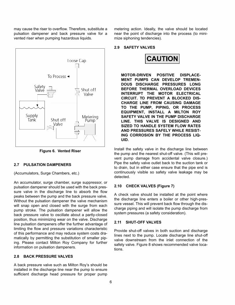
6
may cause the riser to overflow. Therefore, substitute apulsation dampener and back pressure valve for avented riser when pumping hazardous liquids.
2.7 PULSATION DAMPENERS
(Accumulators, Surge Chambers, etc.)
An accumulator, surge chamber, surge suppressor, orpulsation dampener should be used with the back pres-sure valve in the discharge line to absorb the flowpeaks between the pump and the back pressure valve.Without the pulsation dampener the valve mechanismwill snap open and closed with the surge from eachpump stroke. The pulsation dampener will allow theback pressure valve to oscillate about a partly-closedposition, thus minimizing wear on the valve. Dischargeline pulsation dampeners offer the further advantage oflimiting the flow and pressure variations characteristicof this performance and may reduce system costs dra-matically by permitting the substitution of smaller pip-ing. Please contact Milton Roy Company for furtherinformation on pulsation dampeners.
2.8 BACK PRESSURE VALVES
A back pressure valve such as Milton Roy’s should beinstalled in the discharge line near the pump to ensuresufficient discharge head pressure for proper pump
metering action. Ideally, the valve should be locatednear the point of discharge into the process (to mini-mize siphoning tendencies).
2.9 SAFETY VALVES
MOTOR-DRIVEN POSITIVE DISPLACE-MENT PUMPS CAN DEVELOP TREMEN-DOUS DISCHARGE PRESSURES LONGBEFORE THERMAL OVERLOAD DEVICESINTERRUPT THE MOTOR ELECTRICALCIRCUIT. TO PREVENT A BLOCKED DIS-CHARGE LINE FROM CAUSING DAMAGETO THE PUMP, PIPING, OR PROCESSEQUIPMENT, INSTALL A MILTON ROYSAFETY VALVE IN THE PUMP DISCHARGELINE. THIS VALVE IS DESIGNED ANDSIZED TO HANDLE SYSTEM FLOW RATESAND PRESSURES SAFELY WHILE RESIST-ING CORROSION BY THE PROCESS LIQ-UID.
Install the safety valve in the discharge line betweenthe pump and the nearest shut-off valve. (This will pre-vent pump damage from accidental valve closure.)Pipe the safety valve outlet back to the suction tank orto drain, but in either case ensure that the pipe end iscontinuously visible so safety valve leakage may bedetected.
2.10 CHECK VALVES (Figure 7)
A check valve should be installed at the point wherethe discharge line enters a boiler or other high-pres-sure vessel. This will prevent back flow through the dis-charge piping and will isolate the pump discharge fromsystem pressures (a safety consideration).
2.11 SHUT-OFF VALVES
Provide shut-off valves in both suction and dischargelines next to the pump. Locate discharge line shut-offvalve downstream from the inlet connection of thesafety valve. Figure 8 shows recommended valve loca-tions.
Figure 6. Vented Riser

7
Figure 7. Safety and Back Pressure Valves
2.12 SERVICE CONNECTIONS
2.12.1 Pump Drive (Motor Rotation)
Check the nameplate data on the pump drive motorand insure proper power supply is available beforemaking any connections.
The preferred motor shaft rotation is shown by anarrow on the drive side flange of the pump. (MOTORROTATION VIEWED FROM THE FAN END FACINGTHE HOUSING SHOULD BE CLOCKWISE) Runningthe motor in the indicated direction minimizes thepotential for damage to the drive. If running in theopposite direction is required, contact the Milton Royservice department for recommendations.
For drives other than constant speed electric motors,refer to manufacturer’s instructions and service infor-mation included with pump.
2.12.2 Stuffing Box (Packed Plunger Pumps Only)
The stuffing box is designed to handle most clear, free-flowing liquids; however, liquids with suspended solidsand abrasives (e.g., certain slurry and phosphate solu-
tions) tend to precipitate in the packing, causing abnor-mal wear on packing and plunger. An internal flushingconnection used with a V- or Chevron-type packing willminimize this tendency and increase packing andplunger life in these applications. (For abrasive slurryapplications, ball-check valve cartridges should beinstalled remote from pump liquid end. Contact MiltonRoy Company for full details.)
To connect for internal flushing, remove the stuffing boxgrease fitting and connect the stuffing box to a sourceof water (or other compatible liquid) at 25 to 50 psig(172 to 345 kPa) above suction pressure. Since only afew drops per minute are necessary, small diametertubing will suffice. Install a 1/8" or 1/4" NPT stainlesssteel aircraft hydraulic system check valve on the flushline right next to the stuffing box connection to keep theprocess liquid from backing up through the flush line ifthe packing should fail. A 1/8" or 1/4" (3.2 or 6.4 mm)needle valve should be included for controlling theflushing liquid flow rate. The Milroyal B can be fitted atthe factory or in the field with a Swagelok® elbow andtubing to exit through the pump housing for connectionto a flushing line. Contact your Milton Roy representa-tive to order these two parts.

8
Through flush connections to carry hazardous or unde-sirable fluids from the stuffing box can be provided forby drilling and tapping the stuffing box during manufac-ture. In these installations, the flushing liquid is pipedaway from the stuffing box to a drain or other suitabledisposal point. For specific instructions concerning fieldinstallation of through flushing, consult Milton RoyCompany and provide full details of the application.
2.12.3 Drains
Provide drains convenient to the pump so that anyleakage of hazardous fluids may be diverted to suitablecontainer or area. The pump catchall area (beneath thesmall top cover) is provided with a hole drilled andtapped to receive piping for drainage.
2.12.4 Auxiliary (Accessory) Equipment
Service connections for auxiliary or accessory electri-cal equipment should be determined by referring to wir-ing diagrams, instruction manuals, and the data platefurnished with the equipment. Air-operated equipmentshould normally be supplied with two sources of air.The power elements require a standard 60 psig (414kPa) (80-100 psig (552-690 kPa) at compressor) plantair supply (however, an 80 psig (552 kPa) supply (90-100 psig (621-690 kPa) at compressor) is recom-mended to ensure maximum performance under allconditions). Instrument air should be supplied from acontrol instrument or from a manual air pressure regu-lator furnished with 30 psig (207 kPa) service.
Figure 8. Recommended Valve Locations

9
SECTION 3 OPERATION
3.1 INITIAL START-UP
Remove covers (6050 and 6070) from top of pumpcasing and check that interior is free of debris. Rein-stall catchall cover (6070). Install oil cleaning magnet(7040) over the oil pump intake hole on the undersideof the crosshead guide section of the pump casing (seeAssembly Drawing, Figure 10 for magnet location).The magnet is bagged with other loose parts shipped inthe catchall of the pump. Check that all mounting boltsare tight, piping is installed properly, and the dischargeline is open. Fill the pump casing with the lubricantsupplied with the pump; fill to the bottom of the oil levelplug (50) which is located at the level of the crosshead(6-1/2" above the housing feet). A second plug (50) islocated near the bottom of the casing for lubricantdraining. Pour lubricant into the casing over the bear-ings and gear set. (refill amount shown below).Replace cover (6050) over the oil sump.
NOTE: Because gear oil viscosity increases as theambient temperature decreases, you must choosea gear oil appropriate for both the ambient andoperating temperatures. Operating temperaturesare typically 75°F higher than ambient tempera-tures. See below for oil recommendations.
Connect pump motor for clockwise rotation as indi-cated by arrow on pump casing.
3.2 OIL SPECIFICATIONS
GEAR LUBRICANTS
Operating Oil Type Oil RecommendedTemperature*
-30°F to 250°F Mobil SHC 634 Synthetic,ISO 460
-10°F to 40°F Mobil Gear 629, ISO 150
15°F to 125° AGMA #7 Comp., ISO 460
*Maximum Oil Temperature 250°F. The nominal capac-ity of the Milroyal B housing is 20 pints (9.5 liters).
HYDRAULIC FLUIDS
HPD Liquid End & Zurnpreen 15A, ISO 32Disc Diaphragm
3.3 INITIAL ADJUSTMENTS
3.3.1 Micrometer Capacity Control
To adjust pump capacity, loosen the stroke lockingscrew (90, Figure 10) in the casing above themicrometer-adjust hand knob (80), and turn the handknob until the desired capacity percentage is justvisible on the stroke indicator plate (305). Then tightenthe locking screw to maintain capacity setting.
3.3.2 Electric Capacity Control
An Electric Capacity Control may be mounted on thepump housing in place of the micrometer-adjust hand-knob. This accessory adjusts stroke length in responseto manual or automatic electric signals from processcontrol instruments. Electric Capacity Control isdescribed in a separate Instruction Manual (339-0083-000).
3.3.3 Pneumatic Capacity Control
Pneumatic Capacity Control may be mounted on thepump housing in place of the micrometer-adjust hand-knob. This accessory adjusts stroke length in responseto pneumatic signals from a remotely located controlunit. Pneumatic Capacity Control is described in a sep-arate Instruction Manual (339-0017-000).
3.3.4 Speed Capacity Control
Milroyals may be fitted with variable-speed motors toprovide capacity control through adjustments in drivespeed. Such motors and control accessories are avail-able as options from Milton Roy Company.
3.3.5 Capacity Calibration
After the first 12 hours of operation, the pump may betested and calibrated to find the exact pump capacityunder specific operating conditions.
Usually, calibrating the pump at only 100, 50, and 10percent capacity settings is enough to indicate pumpperformance throughout the adjustment range.
The pump can be calibrated by one of two methodscarried out in a given time:

10
1. Measure the decrease in liquid level pumped froma calibrated vessel.
2. Collect and measure pumped liquid at the pumpdischarge port. (It may be necessary to create dis-charge head at the liquid take-off point; otherwisepump will not operate properly. See Section 2 forways to do this.)
The first method is recommended for hazardous liquidsbecause it eliminates operator contact with the liquid.
3.4 FILLING PUMP SYSTEM
It is especially important that pump suction and dis-charge lines be free of entrained air. To ensure thiscondition, operate the pump under no discharge pres-sure and fill the entire pumping system with liquidbefore starting pressure tests.
If the pump is idle for long periods, temperaturechanges in the process liquid may produce air in thesystem. To discharge the air, install a valve in the dis-charge line which will allow the process liquid to bepumped to exhaust when starting the pump.
3.5 PREVENTATIVE MAINTENANCE
Milroyal B pumps are carefully designed, manufac-tured, assembled, and quality tested to give reliableservice with minimal maintenance. However, a daily
maintenance check is recommended to visually con-firm proper operation of the pump.
3.5.1 Drive
Check gear drive oil level monthly and add oil asrequired.
Change gear drive lubricant and clean magnetic filterbelow crosshead chamber every six months or afterevery 2500 hours of operation, whichever occurs first.(This may be scheduled with seasonal oil changes.)
3.5.2 Motor
Lubricate drive motor annually or according to motormanufacturer’s instructions.
3.5.3 Check Valves
Check valve assemblies are designed to be self-clean-ing and should seldom need servicing. Fouled checkvalves can usually be cleaned by pumping a hot deter-gent solution for 15 minutes, followed by water flush-ing.

11
SECTION 4MAINTENANCE
4.1 SPARE PARTS
The spare parts listed in Table 1 should be stocked foreach pump to prevent serious delays in repairs.
Parts orders must include the following information:
1. Quantity (in this manual)
2. Part number (in this manual)
3. Part description (in this manual)
4. Pump serial number (on pump nameplate)
5. Full model number (on pump nameplate)
Always include the serial and model numbers in all cor-respondence regarding the unit.
4.2 RETURNING UNITS TO THE FACTORY
Pumps will not be accepted for repair without a ReturnMaterial Authorization (RMA), available from the Fac-tory Repair Department. Pumps returned to the Factoryfor repairs should be clearly labeled to indicate the liq-uid being pumped. Process liquid should be flushedfrom liquid end before pump is shipped. These safetyprecautions will aid the troubleshooting and repair pro-cedure and preclude injury to repair personnel fromcorrosive residue in pump liquid end. Material SafetyData Sheet must accompany all returns.
All inquiries or parts orders should be addressed toyour local Milton Roy representative or sent to:
Parts Department:
Milton Roy Company
Flow Control Division
201 Ivyland Road
Ivyland, PA 18974
Phone: (215) 441-0800
FAX: (215) 441-8620
Figure 9. Pump Nameplate
4.3 DISASSEMBLY
The pump may be dismantled for parts replacementthrough the following procedures. (Numbers in paren-theses are drawing location numbers found on theparts list and drive drawing, Figure 10)
4.3.1 Pump Drive
The following special tools (PARTSKIT304) will berequired for disassembling the pump drive (crossheadand gear housing):
#211-0022-006 Wrench for tension bearing
#5411-0002-002 Wrench for bearing adjuster
#5411-003-002 Wrench for trunnion
#221-0021-006 Centering tool
#5411-001-002 Torque wrench adapter
4.3.2 Remove the crosshead from the pump as fol-lows (refer to figure 10):
1. Disconnect motor power supply.
Table 1: SPARE PARTS
Drawing Location Reference
Description Qty.Req.
240 Connecting Rod Assembly 1
160 Conical Sleeve Bearings 2
130 Gear Set 1
330 Crosshead Seal 1
190 Worm Shaft Bearings 2
PARTSKIT304
Tool Kit 1

12
2. Remove covers (6050 and 6070). Drain oil frompump casing.
3. Loosen plunger adapter, shown in the liquid endmanual.
4. Remove liquid end from pump drive (See liquid endmanual).
5. Set stroke at 20% and rotate worm until crank ishorizontal. Loosen connecting rod (240) by hand(Use wrench #211-0022-006) and setscrews (5/64allen wrench).
6. Loosen sliding shoe nut (270) and remove slidingshoe set screw (260) from sliding shoe (250).
7. Slowly remove crosshead assembly from liquid endside of pump. Be careful not to lose sliding shoe (incrosshead slot). Take care as well not to damagecrosshead oil seal (330) and crosshead surface fin-ish.
8. Remove crosshead seals if necessary.
NOTE: Be sure not to score seal bore duringremoval.
4.3.3 Remove gear housing from pump drive asfollows:
1. Disconnect motor power supply.
2. Drain oil from pump casing.
3. Loosen connecting rod (240) by hand (Use wrench#211-0022-006), set screws (5/64 allen wrench),and unscrew tension bearing on end of connectingrod from the crank (120).
4. Unbolt and remove motor and motor adapter (520)from pump casing (10).
5. Set capacity adjustment to 0% stroke.
6. Using wrench #5411-002-002 remove bearingadjuster (320).
NOTE: To loosen bearing adjuster and trunnions,heat may have to be applied to release loctite.
7. Support gear housing assembly in position.Remove motor side trunnion (220) with wrench
#5411-003-002 (use heat to release loctite). If bear-ings are being replaced: press tapered roller bear-ing cup from trunnion and remove worm shaft oilseal (310).
8. Withdraw worm shaft from casing. (Bearing coneswill come away with shaft; remaining bearing cupmay stay in trunnion still in casing).
9. Remove second trunnion in same manner asmotor side trunnion. Pull bearing cup from trun-nion if necessary.
10. Lift gear housing (110) from pump casing.
11. To disassemble gear housing assembly, removecrank nut (150) from crank shaft (120) and pullcomponents from crank shaft.
12. Back off stroke locking screw (90). Turn strokeadjustment screw (60) counterclockwise to removeit from pump casing. If the stroke adjustment screwis removed, its O-ring seal (70) should be replaced.
4.4 REASSEMBLY
4.4.1 Pump Drive
Review drawings and then install gear housing in pumpcasing as follows. Thoroughly clean all parts, mainhousing, and male and female threads for reassembly.
1. Heavily coat both sides of the trunnion conicalsleeve bearings (160) with grease. Push the bear-ings into the gear housing bores so that the greasecoating retains each in place.
2. Slowly lower gear assembly into pump casing.Carefully align lead screw keys (170) on either sideof stroke adjustment screw (60).
3. Remove crosshead from pump casing (see “Disas-sembly”). Set capacity adjustment to 0% stroke.Insert centering tool #211-0021-006 in the cross-head bore with its point close to crank-shaft (120).Adjust the two trunnions and the stroke adjustmentscrew until the center hole in the crankshaft alignswith the point of the tool.
4. Align holes in gear housing with trunnion bores inpump casing. “Dry Fit” trunnion and bearingadjuster to ensure threads are clean and there isno binding.
13
HINT: After dry fit, it may be helpfull to loctite oneside at a time as follows: Install both sides “dry”and torque. Now remove one side and add loctite,reinstall, and torque. Then remove other side andadd loctite, reinstall, and torque. Make sure cen-tering tool (221-0021-006) remains centered.
NOTE: Loctite® cures very quickly, allowing only ashort time to complete the following.
Apply Loctite® to trunnion outside threads andinstall trunnions (220) in casing. Turn trunnions inevenly to engage sleeve bearings in gear housing.Take care to seat sleeve bearings in their bores.
5. Using wrench #5411-001-002 and adapter #5411-001-002, alternately tighten trunnions until each istorqued to 35 ft.-lb. (47 N-m) and gear housing isstill centered as in step 4. (On Pneumatic CapacityControl equipped pumps, torque to 30 ft-lb (41 N-m); on Electrical Capacity Control equipped pumps,torque to 12 ft-lb (34 N-m)).
6. Press oil seal (310) into bearing adjuster (320).
7. Apply Loctite® sparingly to bearing cup outsidediameters. Install bearing cup in closed trunnion andinstall the worm shaft with bearing cone seated inbearing cup in trunnion. Install motor side bearingcup in open trunnion.
8. Ensure bearing adjuster threads and inside threadsof open trunnion are completely cleaned of grease.“Dry Fit” parts to ensure threads are clean andthere is no binding. Apply Loctite® sparingly tobearing adjuster outside thread and install bearingadjuster with wrench #5411-002-002. Be careful notto cut oil seal on shaft keyway edges. Ensure propergear set tooth engagement and bearing seating byrotating worm while tightening bearing adjuster tillsnug. After bearing cups are seated, back out bear-ing adjuster 1/2 turn, then tighten to allow only0.0015" (0.0038 mm) lateral running clearance forworm shaft (check with dial indicator from side ofpump casing to end of worm shaft).
9. Now let pump sit undisturbed for at least eighthours at 70°F (21°C) to allow Loctite® to set up.
10. After Loctite® has hardened, coat motor adapterflange bolt threads with liquid sealing compound(e.g., Permatex® #2, non-hardening type) andinstall motor and motor adapter (520) to pump cas-ing.
4.4.2 Reassemble crosshead in casing as follows:
1. Make certain internal oil pump ball-check (20) is inplace in bottom of crosshead bore. Then, with slid-ing shoe (250) in crosshead keyway, install cross-head into crosshead bore, aligning sliding shoe withthe hole for its set screw.
2. Install sliding shoe set screw (260) in place in cas-ing. Tighten set screw till its dog point seats in thesliding shoe against the crosshead, then back outthe set screw 1/4 turn to allow free lateral movementof the crosshead. Lock set screw in place with lock-nut (270).
3. Set stroke adjustment at 20%. Position crank (120)horizontal and move the crosshead toward thecrank so that connecting rod ball can seat in thecrank bearing.
4. Thread connecting rod tension bearing (240) intocrank arm. Tighten the tension bearing to seat theconnecting rod ball in the crank arm. (Use wrench#211-0029-006).
5. Loosen the tension bearing and retighten till con-necting rod is just free enough to rotate with fingers.
6. Tighten both connecting rod (240) set screws using5/64 allen wrench.
7. Install crosshead seal(s) (330) in the followingmanor: Packed plunger drives require one seal (lipfacing gear oil). Disc diaphragm or HPD drivesrequire two seals installed back-to-back (one lip fac-ing gear oil and one lip facing hydraulic oil). Use asuitable tool to drive seals into bore so seals areflush with casting.
NOTE: Do not scratch crosshead surface fin-ish.
8. Set capacity adjustment to 101% stroke. Stop setscrew (15) should hit the gear housing and stop thecapacity adjustment from moving above 101%. Ifnot remove screw, clean, reapply loctite and adjustscrew until it hits gear housing.
9. Install liquid end to pump drive.
4.4.3 Adjusting gear housing for zero stroke and zero micrometer setting.

14
NOTE: The following procedure will adjust leadscrew (60), part of micrometer (80) andstroke stop set screw (15).
1. Move crank (120) one revolution by several turns ofthe worm shaft (130). Watch for zero movement ofthe crosshead (230). Lead screw (60) is adjustedcorrectly to O% setting. This may take severalslight adjustments of the lead screw (60) to accom-plish.
2. Once the crosshead does not move as stated aboveand micrometer set at zero (aligned with strokeplate zero) tighten two micrometer set screws (100)to lead screw (60).
NOTE: Damage to the crosshead (230) by thesliding shoe (250) will occur if themicrometer is alowed to go past 100%.
3. Turn micrometer 10 full turns to 100% stroke set-ting. Tighten stroke stop set screw (15). This insuresstroke adjustment cannot go past 100%.
4. Repeat Paragraph 4.4.3 until desired results areobtained.

15
SECTION 5 TROUBLESHOOTING GUIDE
SYMPTOMS CAUSES REMEDIES
No delivery. • Liquid level is low.
• Blocked discharge line.
• Liquid is frozen.
• Fuse is blown. Replace fuse.
• Open thermal overload device in starter.
• Broken wire.
• Low voltage.
• Pump not primed.
• Add liquid.
• Clear line.
• Thaw liquid through pumping system.
• Replace fuse.
• Reset device.
• Locate and repair.
• Investigate and correct (wiring may be too light).
• Allow suction line and pump head to fill with liquid before pumping against pressure.
Insufficient delivery. • Incorrect capacity adjustment.
• Incorrect pump speed.
• Starved suction.
• Leaky suction piping.
• High suction lift.
• Liquid near boiling.
• Leaky packing.
• Leaky safety valve in discharge line.
• High liquid viscosity.
• Worn or dirty check valve seats.
• Readjust capacity setting.
• Match line voltage and frequency to pump motor data plate.
• Increase piping size or suction head.
• Repair piping.
• Rearrange equipment to decrease lift.
• Cool liquid or increase suction head.
• Adjust or replace packing.
• Repair or replace safety valve.
• Reduce viscosity (e.g., heat or dilute liquid).
• Clean or replace
Erratic delivery. • Leaky suction piping.
• Leaky packing.
• Leaky safety valve.
• Insufficient suction head.
• Liquid near boiling.
• Worn or dirty valve seats.
• Clogged or dirty line strainer.
• Repair piping.
• Adjust or replace packing.
• Repair or replace safety valve.
• Raise suction tank level or pressurize tank.
• Cool liquid or increase suction head.
• Clean or replace.
• Clean strainer.

16
Motor overheating. (Note:Totally enclosed and explo-sion proof motors run hotterthan open motors.)
• Wrong or insufficient gear case lubri-cant.
• Tight or dry packing.
• Operation beyond rated capacity.
• Incorrect power supply.
• Misalignment.
• Over-tightened bearing adjuster.
• Check oil level and type. Replace questionable lubricant.
• Adjust and lubricate packing.
• Constrain operation to specifications.
• Match line voltage and frequency to pump motor data plate.
• Check alignment of moving parts.
• Remove and properly reinstall bearing adjuster.
Oil leakage around worm shaft.
• Damaged or worn oil seal. • Replace seal.
Oil leakage around trunnion. • Insufficient Loctite® applied at assem-bly.
• Disassemble/clean replace Loctite®.
Oil leakage aroundcrosshead. • Damaged or worn seal • Replace seal.
Incorrect zero stroke indica-tion.
• Maladjusted stroke adjusting microme-ter hand knob
• Set pump to zero stroke. (At zero stroke, minimum plunger travel occurs when motor is running.) Loosen stroke adjusting hand knob setscrew, set hand knob to zero, and retighten setscrew.
Minimum stroke limitation. • Misaligned gear housing. • Disassemble pump and reassemble properly aligned.
Gear noise. • Excessive backlash.• Incorrect worm shaft lateral running
clearance.• Worn bearings.• Wrong or insufficient lubricant.
• Adjust backlash or replace gears.• Adjust shaft lateral running clear-ance.
• Replace bearings.• Replace or replenish lubricant.
Loud knock with each stroke. • Insufficient torque on trunnions.• Loose crank nut.• Loose or worn connecting rod tension
bearings.• Worn conical sleeve bearings.• Excessive gear set wear.• Loose clevis.
• Re-torque trunnions.• Tighten nut.• Tighten or replace bearings.
• Replace bearings.• Replace gear set.• Tighten clevis.
Rocking gear housing. • Worn stroke adjusting screw or keys. • Replace worn parts.
Crosshead hesitation. • Loose tension bearing. • Remove and inspect connecting; rein-stall or replace and secure tension bearing.
Crosshead rotation. • Dog point set screw not seated in crosshead sliding shoe.
• Remove crosshead, examine for scor-ing; polish smooth and reinstall.
Worn connecting rod bear-ings.
• Contaminated oil.
• Plugged connecting rod.• Faulty relief valve.• Fouled or missing ball checks in forced
feed lubrication system.
• Replace worn parts and oil and change oil on schedule.
• Clear connecting rod.• Replace relief valve.• Clean or install ball checks.
SYMPTOMS CAUSES REMEDIES

17
SECTION 6PARTS
6.1 GENERAL
1. This section gives information regarding replaceablecomponents.
6.2 ILLUSTRATED PARTS LIST
1. Figure and Item Number Column
a) The item numbers shown in the detailed partslist correspond to the item numbers appearingon the exploded view illustration. To find anunknown part number, locate the part on theillustration and note the item number. Look forthe item number on the detailed parts list. Thepart number is on the same line. A dash (-) pre-cedes non-illustrated item numbers.
2. Description Column
a) The name of the item is in the description col-umn.
3. Part Number Column
a) The supplier’s part number is listed in the partnumber column.
4. Material/SPM Column
a) The material used to manufacture the part islisted in the material/SPM column.
b) The strokes per minute is listed for all wormand shaft assemblies in the material/SPM col-umn.
5. Quantity Column
a) The numbers appearing in the quantity columnare the total quantity of the listed part requiredin its immediate assembly.

18
Figure 10. Drive End View (DWG 102-2095-000)(Sheet 1 of 2)

19
Figure 10. Drive Side and Top Views (DWG 102-2095-000)(Sheet 2 of 2)
20
FIGURE ITEM NUMBER
DESCRIPTION PART NUMBER
QTY OPTIONS
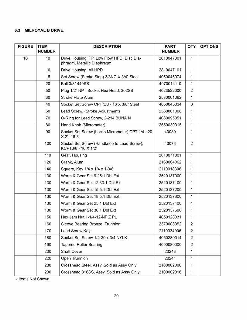
10 10 Drive Housing, PP, Low Flow HPD, Disc Dia-phragm, Metallic Diaphragm
2810047001 1
10 Drive Housing, All HPD 2810047101 1
15 Set Screw (Stroke Stop) 3/8NC X 3/4” Steel 4050045074 1
20 Ball 3/8” 440SS 4070014110 1
50 Plug 1/2” NPT Socket Hex Head, 302SS 4023522000 2
30 Stroke Plate Alum 2530001062 1
40 Socket Set Screw CPT 3/8 - 16 X 3/8” Steel 4050045034 3
60 Lead Screw, (Stroke Adjustment) 2560001006 1
70 O-Ring for Lead Screw, 2-214 BUNA N 4080095051 1
80 Hand Knob (Micrometer) 2550030015 1
90 Socket Set Screw (Locks Micrometer) CPT 1/4 - 20 X 2”, 18-8
40080 1
100 Socket Set Screw (Handknob to Lead Screw), KCPT3/8 - 16 X 1/2”
40073 2
110 Gear, Housing 2810071001 1
120 Crank, Alum 2160004062 1
140 Square, Key 1/4 x 1/4 x 1-3/8 2110018306 1
130 Worm & Gear Set 9.25:1 Dbl Ext 2520137000 1
130 Worm & Gear Set 12.33:1 Dbl Ext 2520137100 1
130 Worm & Gear Set 15.5:1 Dbl Ext 2520137200 1
130 Worm & Gear Set 18.5:1 Dbl Ext 2520137300 1
130 Worm & Gear Set 25:1 Dbl Ext 2520137400 1
130 Worm & Gear Set 36:1 Dbl Ext 2520137600 1
150 Hex Jam Nut 1-1/4-12-NF Z PL 4050128031 1
160 Sleeve Bearing Bronze, Trunnion 2370008052 2
170 Lead Screw Key 2110034006 2
180 Socket Set Screw 1/4-20 x 3/4 NYLK 4050239014 2
190 Tapered Roller Bearing 4090080000 2
200 Shaft Cover 20243 1
220 Open Trunnion 20241 1
230 Crosshead Steel, Assy, Sold as Assy Only 2100002000 1
230 Crosshead 316SS, Assy, Sold as Assy Only 2100002016 1
- Items Not Shown
6.3 MILROYAL B DRIVE.

21
FIGURE ITEM NUMBER
DESCRIPTION PART NUMBER
QTY OPTIONS
10 240 Connecting Rod Assembly, Std. 2140018000 1
250 Sliding Shoe, Steel 26100001006 1
260 Screw, for Sliding Shoe 2560047098 1
270 Hex Nut 1/2 - 13 NC 18.8SS 4050068012 1
280 Gear Oil Valve, Standard or Mid Range (config code ST, H2, 11, or HS
H4070125000 1
280 Gear Oil Valve, High Range (config code H3 or HH):(Contains P/N 41112 and 41113)
See Below 1
280 Body, REL VLV, 10-2 CAV, ALUM 41112 1
280 Relief Valve Cartridge, 150-1300 PSI 41113 1
281 Connector, Strait, 1/4 SWG 3/8 NPTM STL 4020363073 1
282 Tubing 1/4 X 0.028 - 0.035 Wall STL 5160061006 1.25 IN.
283 Elbow, 1/4T x 1/4 NPT Steel 4020057021 1
284 Street Elbow SS-6-SE 1
285 NIPTHRDSCH40 3/8 x 2 316SS 4020051033 1
310 Seal, Worm Shaft 4080031050 1
320 Bearing Adjuster 2370002006 1
330 Crosshead, Oil Seal (Qty 1 for Pack Plunger Pumps)
4080031020 2
520 Motor Adapter, (Frame 56C Mount) 2720027001 1
520 Motor Adapter, (Frame 143/145TC, 182/184C) 2720027001 1
520 Motor Adapter, (Frame 182/184TC, 213/215TC) 2720043201 1
520 Motor Adapter, (Frame Metric 80) 3050330060 1
520 Motor Adapter, (Frame Metric 90) 3050330100 1
520 Motor Adapter, (Frame Metric 100) 3050330070 1
521 Motor Adapter Ring, (Frame 213/215TC) 21382 1
530 Spring Lock Washer, 3/8 18.8SS (No Motor Mount) 4040041022 2
530 Spring Lock Washer, 3/8 18.8SS (Frame 56C Mount)
4040041022 8
530 Spring Lock Washer, 3/8 18.8SS, (Frame 143/145TC 182/184C)
4040041022 8
530 Spring Lock Washer, 3/8 18.8SS, (Frame 182/184TC, 213/215TC)
4040041022 4
530 Spring Lock Washer, 3/8 18.8SS, (Frame Metric 80, 90, & 100)
4040041022 4
540 Hex Head Screw, 3/8 - 16 X 3/4, Ultra (No Motor Mount)
4050018096 4
- Items Not Shown
22
FIGURE ITEM NUMBER
DESCRIPTION PART NUMBER
QTY OPTIONS
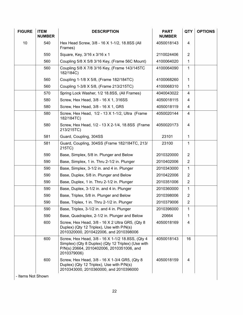
10 540 Hex Head Screw, 3/8 - 16 X 1-1/2, 18.8SS (All Frames)
4050018143 4
550 Square, Key, 3/16 x 3/16 x 1 2110024406 2
560 Coupling 5/8 X 5/8 3/16 Key, (Frame 56C Mount) 4100064020 1
560 Coupling 5/8 X 7/8 3/16 Key, (Frame 143/145TC 182/184C)
4100064090 1
560 Coupling 1-1/8 X 5/8, (Frame 182/184TC) 4100068260 1
560 Coupling 1-3/8 X 5/8, (Frame 213/215TC) 4100068310 1
570 Spring Lock Washer, 1/2 18.8SS, (All Frames) 4040043022 4
580 Screw, Hex Head, 3/8 - 16 X 1, 316SS 4050018115 4
580 Screw, Hex Head, 3/8 - 16 X 1, GR5 4050018119 4
580 Screw, Hex Head, 1/2 - 13 X 1-1/2, Ultra (Frame 182/184TC)
4050020144 4
580 Screw, Hex Head, 1/2 - 13 X 2-1/4, 18.8SS (Frame 213/215TC)
4050020173 4
581 Guard, Coupling, 304SS 23101 1
581 Guard, Coupling, 304SS (Frame 182/184TC, 213/215TC)
23100 1
590 Base, Simplex, 5/8 in. Plunger and Below 2010320000 2
590 Base, Simplex, 1 in. Thru 2-1/2 in. Plunger 2010402006 2
590 Base, Simplex, 3-1/2 in. and 4 in. Plunger 2010343000 1
590 Base, Duplex, 5/8 in. Plunger and Below 2010422006 2
590 Base, Duplex, 1 in. Thru 2-1/2 in. Plunger 2010351006 2
590 Base, Duplex, 3-1/2 in. and 4 in. Plunger 2010360000 1
590 Base, Triplex, 5/8 in. Plunger and Below 2010398006 2
590 Base, Triplex, 1 in. Thru 2-1/2 in. Plunger 2010379006 2
590 Base, Triplex, 3-1/2 in. and 4 in. Plunger 2010396000 1
590 Base, Quadraplex, 2-1/2 in. Plunger and Below 20664 1
600 Screw, Hex Head, 3/8 - 16 X 2 Ultra GR5, (Qty 8 Duplex) (Qty 12 Triplex), Use with P/N(s) 2010320000, 2010422006, and 2010398006
4050018169 4
600 Screw, Hex Head, 3/8 - 16 X 1-1/2 18.8SS, (Qty 4 Simplex) (Qty 8 Duplex) (Qty 12 Triplex) (Use with P/N(s) 20664, 2010402006, 2010351006, and 2010379006)
4050018143 16
600 Screw, Hex Head, 3/8 - 16 X 1-3/4 GR5, (Qty 8 Duplex) (Qty 12 Triplex), Use with P/N(s) 2010343000, 2010360000, and 2010396000
4050018159 4
- Items Not Shown
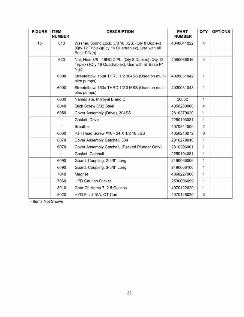
23
FIGURE ITEM NUMBER
DESCRIPTION PART NUMBER
QTY OPTIONS
10 610 Washer, Spring Lock, 3/8 18.8SS, (Qty 8 Duplex) (Qty 12 Triplex)(Qty 16 Quadraplex), Use with all Base P/N(s)
4040041022 4
620 Nut, Hex, 3/8 - 16NC Z PL, (Qty 8 Duplex) (Qty 12 Triplex) (Qty 16 Quadraplex), Use with all Base P/N(s)
4050066016 4
6000 Streetelbow, 150# THRD 1/2 304SS (Used on multi-plex pumps)
4020031042 1
6000 Streetelbow, 150# THRD 1/2 316SS (Used on multi-plex pumps)
4020031043 1
6030 Nameplate, Milroyal B and C 20662 1
6040 Stick Screw 5/32 Steel 4050280000 4
6050 Cover Assembly (Drive), 304SS 2810279020 1
- Gasket, Drive 2250103081 1
- Breather 4070344000 2
6060 Pan Head Screw #10 - 24 X 1/2 18.8SS 4050213072 8
6070 Cover Assembly Catchall, 304 2810279010 1
6070 Cover Assembly Catchall, (Packed Plunger Only) 2810296001 1
- Gasket, Catchall 2250104081 1
6090 Guard, Coupling, 2-3/8” Long 2490066006 1
6090 Guard, Coupling, 3-3/8” Long 2490066106 1
7040 Magnet 4060227000 1
7060 HPD Caution Sticker 2530006099 1
8010 Gear Oil Agma 7, 2.5 Gallons 4070122020 1
8020 HYD Fluid 15A, QT Can 4070126020 3
- Items Not Shown

24
SERVICE RECORD
Pump Model No.
Pump Serial No. Liquid Pumped
This page is designed as an aid in maintaining the Milroyal pump. Common service operations arelisted here with general recommendations based on Service Department field experience.
Gear Drive Lubricant. Monthly inspection of level and condition is recommended. Also recom-mended is replacement of the lubricant 90 days after the pump is first placed in service. Thereafter,change the lubricant at 6 month or 2500 hour intervals (whichever occurs first).
Supply Tank and Piping. Clean and flush annually.
Suction Line Strainer. Clean as required.
Ball-Check Valves. Flush with clean liquid as often as necessary to maintain full metering accu-racy.
SERVICE OPERATOR DATE HOURS REMARKS

25
TABLE OF EQUIVALENTS
1 atmosphere equals 1.0333 kilograms/square centimeter
101.33 kilopascals1.0135 bars
1 Btu/hour equals .2928 Watts
Degrees Fahrenheit equals 1.8° Celsius + 32
1 Angler degree equals 7.45 square millimeters/second
1 foot equals 30.48 centimeters12 inches
1 Ford cup #4 equals 3.76 square millimeters/second
1 gallon (U.S.) equals .1337 cubic feet.8333 Imperial gallons3.785 liters4 quarts
1 gallon/hour (U.S.) equals .003785 cubic meters/hour.002228 cubic feet/minute
1 horsepower equals 745.7 Watts
1 inch equals 2.540 centimeters
1 inch of mercury equals .03442 kilograms/square centimeter3376.5 Pascals.4897 pounds/square inch
1 pint (liquid) equals .4732 liters16 ounces
1 pound/square inch equals .06804 atmospheres.06897 bars.07029 kilograms/square centimeter6894.8 Pascals
1 Redwood Admiralty equals 2.340 square millimeters/second
1 Redwood Standard equals .237 square millimeters/second
1 Saybolt Furol equals 2.16 square millimeters/second
1 Saybolt Second equals .216 square millimeters/secondUniversal

www.miltonroy.com
201 Ivyland Road • Ivyland, PA 18974 USA • (215) 441-0800 • Fax: (215) 441-8620 • E-mail: [email protected]
MILROYAL ® is a registered trademark of Milton Roy Company.


![airsystems-llc.com · [00000] Air Systems, LLC 4512 Bishop Lane Louisville KY 40218 United States](https://img.pdfslide.us/doc/110x75/5c4b6d0f93f3c3245e2716ce/airsystems-llccom-00000-air-systems-llc-4512-bishop-lane-louisville-ky-40218.jpg)