Embed Size (px)
Citation preview
Instruction Manual February 2004
BW100milltronics
MILLTRONICS BW100

© Siemens Milltronics Process Instruments Inc. 2004
Safety Guidelines
Warning notices must be observed to ensure personal safety as well as that of others, and toprotect the product and the connected equipment. These warning notices are accompaniedby a clarification of the level of caution to be observed.
Qualified Personnel
This device/system may only be set up and operated in conjunction with this manual.Qualified personnel are only authorized to install and operate this equipment in accordancewith established safety practices and standards.
Warning: This product can only function properly and safely if it is correctly transported,stored, installed, set up, operated, and maintained.
Note: Always use product in accordance with specifications.
Copyright Siemens Milltronics ProcessInstruments Inc. 2004. All Rights Reserved
Disclaimer of Liability
This document is available in bound version and inelectronic version. We encourage users topurchase authorized bound manuals, or to viewelectronic versions as designed and authored bySiemens Milltronics Process Instruments Inc.Siemens Milltronics Process Instruments Inc. willnot be responsible for the contents of partial orwhole reproductions of either bound or electronicversions.
While we have verified the contents ofthis manual for agreement with theinstrumentation described, variationsremain possible. Thus we cannotguarantee full agreement. Thecontents of this manual are regularlyreviewed and corrections are includedin subsequent editions. We welcomeall suggestions for improvement.
Technical data subject to change.
MILLTRONICS®is a registered trademark of Siemens Milltronics Process Instruments Inc.
Contact SMPI Technical Publications at the following address:
Technical PublicationsSiemens Milltronics Process Instruments Inc.1954 Technology Drive, P.O. Box 4225Peterborough, Ontario, Canada, K9J 7B1Email: [email protected]
For the library of SMPI instruction manuals, visit our Web site: www.siemens-milltronics.com
i
mm
mm
m
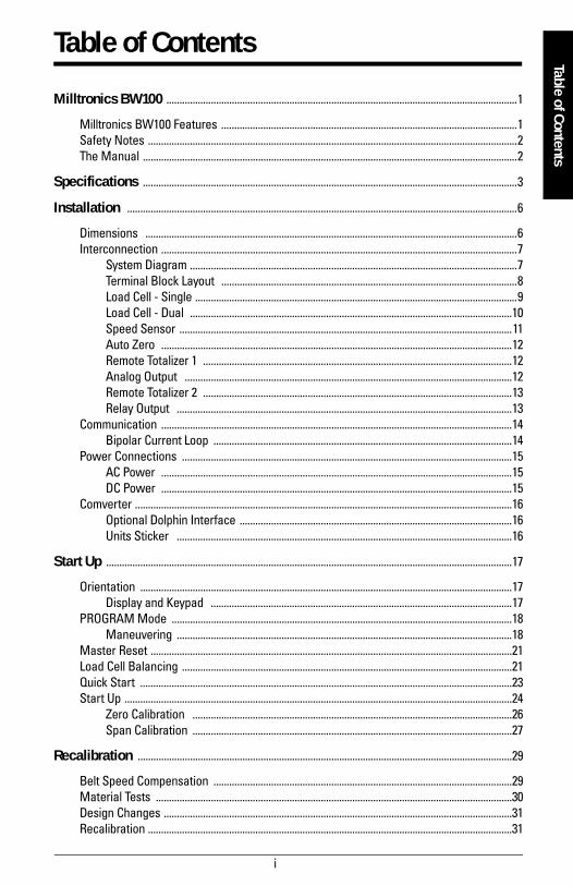
Table of Contents
Table of Contents
Milltronics BW100 ......................................................................................................................................1
Milltronics BW100 Features .................................................................................................................1Safety Notes .............................................................................................................................................2The Manual ...............................................................................................................................................2
Specifications ...............................................................................................................................................3
Installation .....................................................................................................................................................6
Dimensions ..............................................................................................................................................6Interconnection ........................................................................................................................................7
System Diagram .............................................................................................................................7Terminal Block Layout .................................................................................................................8Load Cell - Single ...........................................................................................................................9Load Cell - Dual ...........................................................................................................................10Speed Sensor ...............................................................................................................................11Auto Zero ......................................................................................................................................12Remote Totalizer 1 ......................................................................................................................12Analog Output .............................................................................................................................12Remote Totalizer 2 ......................................................................................................................13Relay Output ................................................................................................................................13
Communication ......................................................................................................................................14Bipolar Current Loop ..................................................................................................................14
Power Connections ..............................................................................................................................15AC Power ......................................................................................................................................15DC Power ......................................................................................................................................15
Comverter ................................................................................................................................................16Optional Dolphin Interface ........................................................................................................16Units Sticker ................................................................................................................................16
Start Up ...........................................................................................................................................................17
Orientation ..............................................................................................................................................17Display and Keypad ...................................................................................................................17
PROGRAM Mode ..................................................................................................................................18Maneuvering ................................................................................................................................18
Master Reset ..........................................................................................................................................21Load Cell Balancing ..............................................................................................................................21Quick Start ..............................................................................................................................................23Start Up ....................................................................................................................................................24
Zero Calibration ..........................................................................................................................26Span Calibration ..........................................................................................................................27
Recalibration ...............................................................................................................................................29
Belt Speed Compensation ..................................................................................................................29Material Tests ........................................................................................................................................30Design Changes .....................................................................................................................................31Recalibration ...........................................................................................................................................31
ii
Routine Zero .................................................................................................................................32Initial Zero .....................................................................................................................................33Direct Zero ....................................................................................................................................34Routine Span ................................................................................................................................35Initial Span ...................................................................................................................................36Direct Span ...................................................................................................................................37
Factoring ..................................................................................................................................................38Linearization ...........................................................................................................................................39
Operation .......................................................................................................................................................42
Load Sensing ..........................................................................................................................................42Speed Sensing .......................................................................................................................................42Modes of Operation ..............................................................................................................................42Damping ...................................................................................................................................................43Analog Output ........................................................................................................................................43Relay Output ...........................................................................................................................................44Totalization ..............................................................................................................................................45Auto Zero .................................................................................................................................................46
Communications ........................................................................................................................................47
Protocol ....................................................................................................................................................47Data Field Descriptions ..............................................................................................................48Message Requests .....................................................................................................................48Message Responses ..................................................................................................................49
Parameters ....................................................................................................................................................50
Quick Start (P005 to P017) ..................................................................................................................50Relay/Alarm Function (P100 - P117) .................................................................................................53mA Output Parameters (P200 - P220) ..............................................................................................53Load Cell Balancing Parameters (P291 - P295) .............................................................................55Linearization Parameters (P390 - P396) ..........................................................................................57Totalization (P619 - P648) .....................................................................................................................58Communication (P751 - P761) .............................................................................................................61Test and Diagnostic (P900 - P951) ....................................................................................................62
Troubleshooting ..........................................................................................................................................65
Maintenance ..........................................................................................................................................67Software Updates .................................................................................................................................67
Appendix ........................................................................................................................................................68
Alphabetical Parameter List ...............................................................................................................68Program Record .....................................................................................................................................70
Index .................................................................................................................................................................72

7ML19985DJ01 Milltronics BW100 - INSTRUCTION MANUAL Page 1
mm
mm
m
Introduction
Milltronics BW100
The Milltronics BW100 is an economical integrator for use with belt scales. The speed and load signals from the conveyor and scale, are processed to derive rate of material flow and totalization.
The primary values of speed and load, and the derived values of rate and total are available for display on the local LCD, or as output in the form of analog mA, alarm relay and remote totalization. BW100 supports Milltronics proprietary bipolar current loop for long distance communication to PLC or computer. It is also compatible with Milltronics Dolphin interface for remote display, programming and software upgrading.
Milltronics BW100 Features multi-field LCD display two remote totalizer contacts current loop for communications Dolphin compatibility programmable relay isolated mA output rate linearization local keypad Auto Zero
Note: The Milltronics BW100 is to be used only in the manner outlined in this instruction manual.
Load SpeedMaterial
total

Page 2 Milltronics BW100 - INSTRUCTION MANUAL 7ML19985DJ01
mm
mm
m
Intr
oduc
tion
Safety NotesSpecial attention must be paid to warnings and notes highlighted from the rest of the text by grey boxes.
The ManualIt is essential to refer to thismanual for proper installation and operation of your BW100 belt scale integrator. As the BW100 must be connected to a belt scale, and optionally a speed sensor, refer to their manuals as well.
The manual is designed to help you get the most out of your BW100, and it provides information on the following
If you have any questions, comments, or suggestions about the manual contents, please email us at [email protected].
For the complete library of Siemens Milltronics manuals, go to www.siemens-milltronics.com.
WARNING means that failure to observe the necessary precautions can result in death, serious injury, and/or considerable material damage.
Note: means important information about the product or that part of the operating manual.
How to install the unit How to program the unit How to operate the keypad
and read the display How to do an initial Start Up How to optimize and
maintain accurate operation of the unit
Outline diagrams Wiring diagrams Parameter values Parameter uses Modbus register mapping Modem configuration
Note: The Milltronics BW100 is to be used only in the manner outlined in this instruction manual.
7ML19985DJ01 Milltronics BW100 - INSTRUCTION MANUAL Page 3
mm
mm
m
Specifications
Specifications
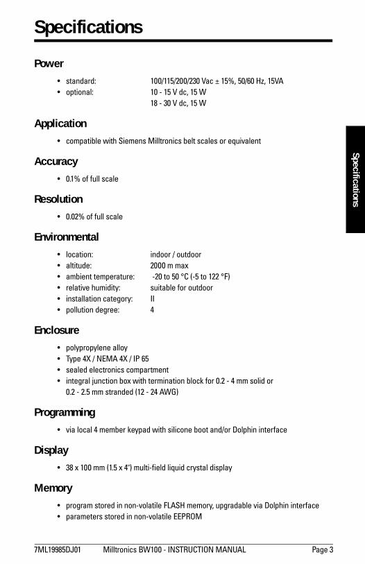
Power standard: 100/115/200/230 Vac ± 15%, 50/60 Hz, 15VA optional: 10 - 15 V dc, 15 W
18 - 30 V dc, 15 W
Application compatible with Siemens Milltronics belt scales or equivalent
Accuracy 0.1% of full scale
Resolution 0.02% of full scale
Environmental location: indoor / outdoor altitude: 2000 m max ambient temperature: -20 to 50 °C (-5 to 122 °F) relative humidity: suitable for outdoor installation category: II pollution degree: 4
Enclosure polypropylene alloy Type 4X / NEMA 4X / IP 65 sealed electronics compartment integral junction box with termination block for 0.2 - 4 mm solid or
0.2 - 2.5 mm stranded (12 - 24 AWG)
Programming via local 4 member keypad with silicone boot and/or Dolphin interface
Display 38 x 100 mm (1.5 x 4") multi-field liquid crystal display
Memory program stored in non-volatile FLASH memory, upgradable via Dolphin interface parameters stored in non-volatile EEPROM
Page 4 Milltronics BW100 - INSTRUCTION MANUAL 7ML19985DJ01
mm
mm
m
Spec
ifica
tions
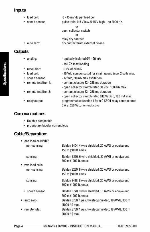
Inputs load cell: 0 - 45 mV dc per load cell speed sensor: pulse train: 0-5 V low, 5-15 V high, 1 to 2000 Hz,
oropen collector switch
or relay dry contact
auto zero: dry contact from external device
Outputs analog: - optically isolated 0/4 - 20 mA
- 750 Ω max loading resolution: - 0.1% of 20 mA load cell: - 10 Vdc compensated for strain gauge type, 2 cells max speed sensor: - 12 Vdc, 50 mA max excitation remote totalizer 1: - contact closure 32 - 288 ms duration
- open collector switch rated 30 Vdc, 100 mA max remote totalizer 2: - contact closure 32 - 288 ms duration
- open collector switch rated 240 Vac/dc, 100 mA max relay output: programmable function 1 form C SPDT relay contact rated
5 A at 250 Vac, non-inductive
Communications Dolphin compatible proprietary bipolar current loop
Cable/Separation: one load cell/LVDT:
non-sensing: Belden 8404, 4 wire shielded, 20 AWG or equivalent, 150 m (500 ft.) max.
sensing: Belden 9260, 6 wire shielded, 20 AWG or equivalent,300 m (1000 ft.) max.
two load cells:non-sensing: Belden 9260, 6 wire shielded, 20 AWG or equivalent,
150 m (500 ft.) max.
sensing: Belden 8418, 8 wire shielded, 20 AWG or equivalent, 300 m (1000 ft.) max.
speed sensor Belden 8770, 3 wire shielded, 18 AWG or equivalent, 300 m (1000 ft.) max.
auto zero: Belden 8760, 1 pair, twisted/shielded, 18 AWG, 300 m (1000 ft.) max.
remote total: Belden 8760, 1 pair, twisted/shielded, 18 AWG, 300 m (1000 ft.) max.
7ML19985DJ01 Milltronics BW100 - INSTRUCTION MANUAL Page 5
mm
mm
m
Specifications
analog output: Belden 8760, 1 pair, twisted/shielded, 18 AWG or equivalent
bipolar current: Belden 9552, 2 pair, twisted/shielded, 18 (comm. port) AWG, 3000 m (10,000 ft.) max. loop remote total Belden 8760, 1 pair, twisted/shielded, 18AWG, t1 (dc) 300 m (1000 ft.) max.
Options: Speed Sensor: - Siemens Milltronics MD-36 series, or equivalent Dolphin: - Milltronics Windows based software interface and
infrared ComVerter link
Approvals: CE*, CSA NRTL/C
*EMC performance available upon request
Page 6 Milltronics BW100 - INSTRUCTION MANUAL 7ML19985DJ01
mm
mm
m
Inst
alla
tion
Installation
Dimensions
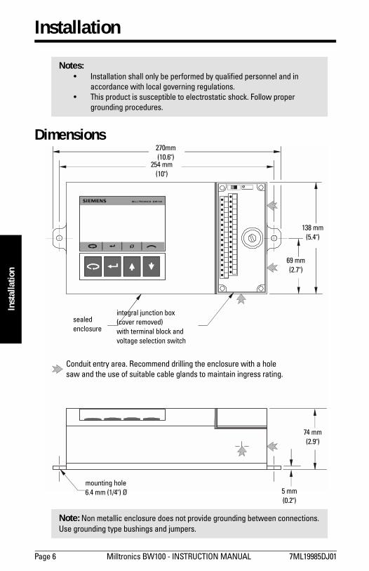
Notes: Installation shall only be performed by qualified personnel and in
accordance with local governing regulations. This product is susceptible to electrostatic shock. Follow proper
grounding procedures.
Note: Non metallic enclosure does not provide grounding between connections. Use grounding type bushings and jumpers.
Conduit entry area. Recommend drilling the enclosure with a hole saw and the use of suitable cable glands to maintain ingress rating.
270mm(10.6")
254 mm(10")
138 mm(5.4")
69 mm(2.7")
sealed enclosure
integral junction box(cover removed)with terminal block andvoltage selection switch
mounting hole6.4 mm (1/4") Ø 5 mm
(0.2")
74 mm(2.9")
7ML19985DJ01 Milltronics BW100 - INSTRUCTION MANUAL Page 7
mm
mm
m
Installation
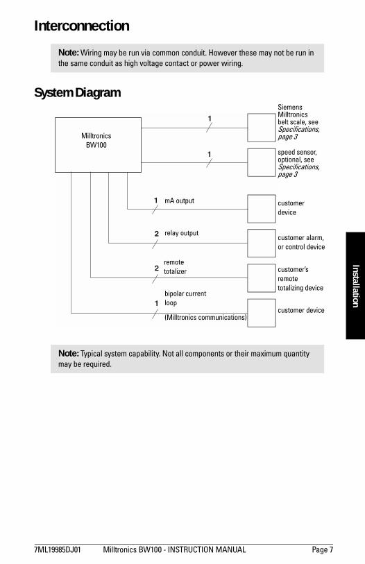
Interconnection
System Diagram
Note: Wiring may be run via common conduit. However these may not be run in the same conduit as high voltage contact or power wiring.
Note: Typical system capability. Not all components or their maximum quantity may be required.
1
2
2
1
1
1
MilltronicsBW100
mA output
relay output
remote totalizer
bipolar current loop
(Milltronics communications)
Siemens Milltronicsbelt scale, seeSpecifications, page 3
customerdevice
customers remotetotalizing device
customer device
speed sensor, optional, see Specifications, page 3
customer alarm,or control device
Page 8 Milltronics BW100 - INSTRUCTION MANUAL 7ML19985DJ01
mm
mm
m
Inst
alla
tion
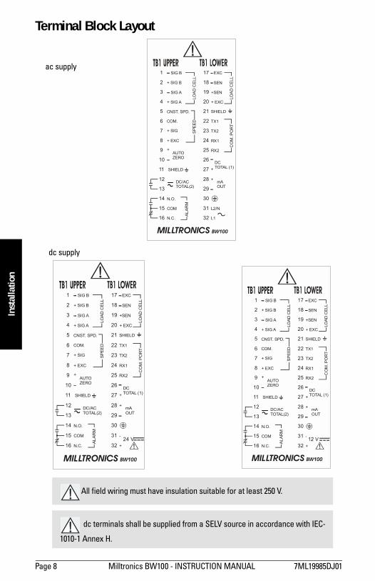
Terminal Block Layout
All field wiring must have insulation suitable for at least 250 V.
dc terminals shall be supplied from a SELV source in accordance with IEC-
1010-1 Annex H.
1 17- SIG B - EXC
+ SIG B - SEN
- SIG A +SEN
+ SIG A + EXC
CNST. SPD. SHIELD
TX1
RX1
RX2
DCTOTAL (1)+
mAOUT
+
-
+
+ SIG
COM.
+ EXC
TX2
SHIELD
AUTOZERO
DC/ACTOTAL(2)
COM
N.O.
N.C.
+
5 21
9 25
13 29
2 18
6 22
10 26
14 30
3 19
7 23
11 27
15 31
4 20
8 24
12 28
16 32
LOA
D C
ELL
SPE
ED
LOA
D C
ELL
CO
M. P
OR
T
ALAR
M
MILLTRONICS BW100
1 17- SIG B - EXC
+ SIG B - SEN
- SIG A +SEN
+ SIG A + EXC
CNST. SPD. SHIELD
TX1
RX1
RX2
DCTOTAL (1)+
mAOUT
+
-
+
+ SIG
COM.
+ EXC
TX2
SHIELD
AUTOZERO
DC/ACTOTAL(2)
COM
N.O.
N.C.
+
5 21
9 25
13 29
2 18
6 22
10 26
14 30
3 19
7 23
11 27
15 31
4 20
8 24
12 28
16 32
LOAD
CE
LLS
PE
ED
LOAD
CE
LLC
OM
. PO
RT
ALA
RM
24 V
MILLTRONICS BW100
1 17- SIG B - EXC
+ SIG B - SEN
- SIG A +SEN
+ SIG A + EXC
CNST. SPD. SHIELD
TX1
RX1
RX2
DCTOTAL (1)+
mAOUT
+
L2/N
L1
+ SIG
COM.
+ EXC
TX2
SHIELD
AUTOZERO
DC/ACTOTAL(2)
COM
N.O.
N.C.
+
5 21
9 25
13 29
2 18
6 22
10 26
14 30
3 19
7 23
11 27
15 31
4 20
8 24
12 28
16 32
LOAD
CE
LLS
PEE
D
LOAD
CE
LLC
OM
. PO
RT
ALAR
M
MILLTRONICS BW100
ac supply
dc supply
7ML19985DJ01 Milltronics BW100 - INSTRUCTION MANUAL Page 9
mm
mm
m
Installation
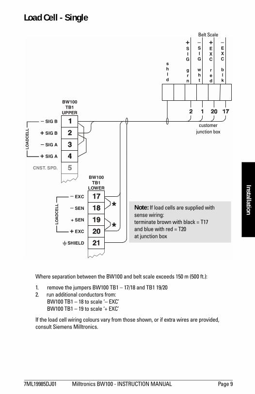
Load Cell - Single
Where separation between the BW100 and belt scale exceeds 150 m (500 ft.):
1. remove the jumpers BW100 TB1 17/18 and TB1 19/20 2. run additional conductors from:
BW100 TB1 18 to scale EXC BW100 TB1 19 to scale + EXC
If the load cell wiring colours vary from those shown, or if extra wires are provided, consult Siemens Milltronics.
*
*
BW100TB1
UPPER
BW100TB1
LOWER
SIG B
EXC
LO
AD
CE
LL
LO
AD
CE
LL
+ SIG B
SEN
SIG A
+ SEN
+ SIG A
+ EXC
shld
+SIG
grn
SIG
wht
+EXC
red
EXC
blk
CNST. SPD.
SHIELD
customerjunction box
Note: If load cells are supplied with sense wiring:terminate brown with black = T17and blue with red = T20at junction box
Belt Scale
Page 10 Milltronics BW100 - INSTRUCTION MANUAL 7ML19985DJ01
mm
mm
m
Inst
alla
tion
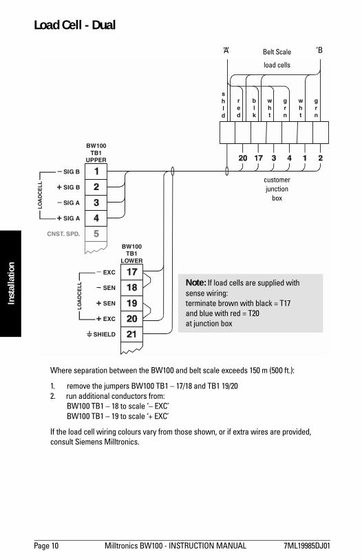
Load Cell - Dual
Where separation between the BW100 and belt scale exceeds 150 m (500 ft.):
1. remove the jumpers BW100 TB1 17/18 and TB1 19/20 2. run additional conductors from:
BW100 TB1 18 to scale EXC BW100 TB1 19 to scale + EXC
If the load cell wiring colours vary from those shown, or if extra wires are provided, consult Siemens Milltronics.
BW100TB1
UPPER
BW100TB1
LOWER
SIG B
EXC
+ SIG B
SEN
SIG A
+ SEN
+ SIG A
+ EXC
shld
blk
red
wht
grn
wht
grn
CNST. SPD.
SHIELD
LO
AD
CE
LL
LO
AD
CE
LL
Belt Scale
load cells
A B
customerjunction
box
Note: If load cells are supplied with sense wiring:terminate brown with black = T17and blue with red = T20at junction box
7ML19985DJ01 Milltronics BW100 - INSTRUCTION MANUAL Page 11
mm
mm
m
Installation
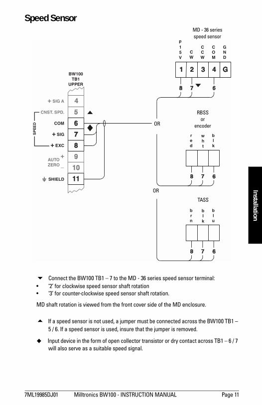
Speed Sensor
! Connect the BW100 TB1 7 to the MD - 36 series speed sensor terminal: 2 for clockwise speed sensor shaft rotation 3 for counter-clockwise speed sensor shaft rotation.
MD shaft rotation is viewed from the front cover side of the MD enclosure.
# If a speed sensor is not used, a jumper must be connected across the BW100 TB1 5 / 6. If a speed sensor is used, insure that the jumper is removed.
! Input device in the form of open collector transistor or dry contact across TB1 6 / 7 will also serve as a suitable speed signal.
BW100TB1
UPPER
+ SIG A
CNST. SPD.
COM
+ SIG
+ EXC
AUTOZERO
+
CW
P15V
red
CCW
blk
COM
GND
SHIELD
SP
EE
D
wht
brn
blu
blk
OR
RBSSor
encoder
MD - 36 seriesspeed sensor
OR
TASS
Page 12 Milltronics BW100 - INSTRUCTION MANUAL 7ML19985DJ01
mm
mm
m
Inst
alla
tion
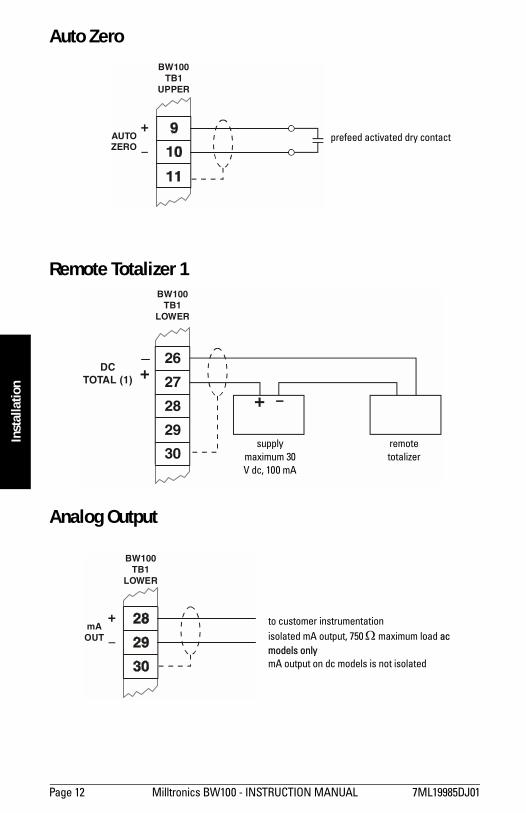
Auto Zero
Remote Totalizer 1
Analog Output
BW100TB1
UPPER
AUTOZERO
+prefeed activated dry contact
26
27
28
29
30
BW100TB1
LOWER
-+
DCTOTAL (1) +
supplymaximum 30V dc, 100 mA
remotetotalizer
BW100TB1
LOWER
mAOUT
+ to customer instrumentation isolated mA output, 750 Ω maximum load ac models only mA output on dc models is not isolated
7ML19985DJ01 Milltronics BW100 - INSTRUCTION MANUAL Page 13
mm
mm
m
Installation
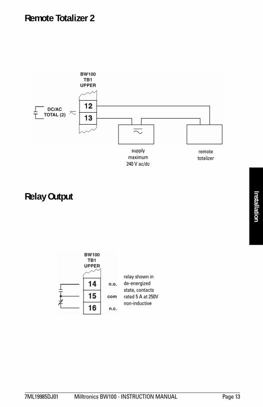
Remote Totalizer 2
Relay Output
BW100TB1
UPPER
DC/ACTOTAL (2)
supplymaximum
240 V ac/dc
remotetotalizer
BW100TB1
UPPER
n.o.
com
n.c.
relay shown inde-energizedstate, contactsrated 5 A at 250V non-inductive
Page 14 Milltronics BW100 - INSTRUCTION MANUAL 7ML19985DJ01
mm
mm
m
Inst
alla
tion
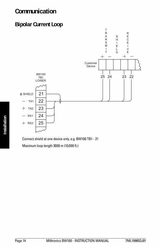
Communication
Bipolar Current Loop
Connect shield at one device only, e.g. BW100 TB1 - 21
Maximum loop length 3000 m (10,000 ft.)
21
25 24 23 22
22232425
BW100TB1
LOWER
CustomerDevice
TX1
TX2
RX1
TRANSMIT
SHIELD
RECEIVE
RX2
SHIELD
7ML19985DJ01 Milltronics BW100 - INSTRUCTION MANUAL Page 15
mm
mm
m
Installation
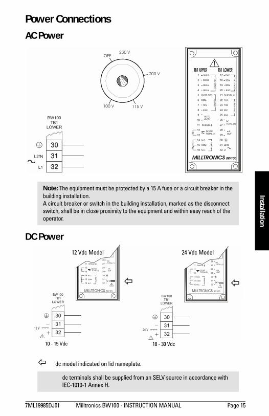
Power Connections AC Power
DC Power
" dc model indicated on lid nameplate.
Note: The equipment must be protected by a 15 A fuse or a circuit breaker in the building installation. A circuit breaker or switch in the building installation, marked as the disconnect switch, shall be in close proximity to the equipment and within easy reach of the operator.
dc terminals shall be supplied from an SELV source in accordance with IEC-1010-1 Annex H.
BW100TB1
LOWER
L2/N
L1
OFF230 V
115 V100 V
200 V 1 17- SIG B - EXC
+ SIG B - SEN
- SIG A +SEN
+ SIG A + EXC
CNST. SPD. SHIELD
TX1
RX1
RX2
DCTOTAL (1)+
mAOUT
+
L2/N
L1
+ SIG
COM.
+ EXC
TX2
SHIELD
AUTOZERO
DC/ACTOTAL(2)
COM
N.O.
N.C.
+
5 21
9 25
13 29
2 18
6 22
10 26
14 30
3 19
7 23
11 27
15 31
4 20
8 24
12 28
16 32
LOAD
CEL
LS
PEE
D
LOAD
CEL
LC
OM
. PO
RT
ALAR
M
MILLTRONICS BW100
303132
BW100TB1
LOWER
é+12 V
DCTOTAL (1)+
mAOUT
+
SHIELD
DC/ACTOTAL(2)
COM
N.O.
N.C.
13 29
26
14 30
11 27
15 31
12 28
16 32ALA
RM
303132
BW100TB1
LOWER
é+24 V
DCTOTAL (1)+
mAOUT
+
SHIELD
DC/ACTOTAL(2)
COM
N.O.
N.C.
13 29
26
14 30
11 27
15 31
12 28
16 32
ALAR
M
MILLTRONICS BW100MILLTRONICS BW100
10 - 15 Vdc 18 - 30 Vdc
12 Vdc Model 24 Vdc Model
" "
Page 16 Milltronics BW100 - INSTRUCTION MANUAL 7ML19985DJ01
mm
mm
m
Inst
alla
tion
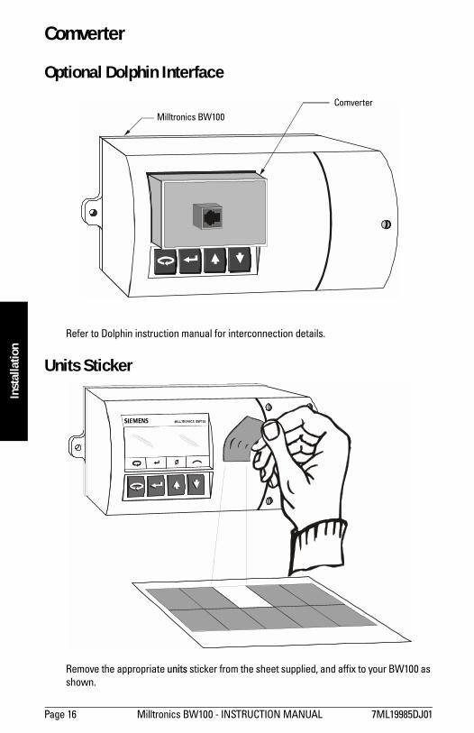
Comverter
Optional Dolphin Interface
Refer to Dolphin instruction manual for interconnection details.
Units Sticker
Remove the appropriate units sticker from the sheet supplied, and affix to your BW100 as shown.
Comverter
Milltronics BW100
7ML19985DJ01 Milltronics BW100 - INSTRUCTION MANUAL Page 17
mm
mm
m
Installation
Start Up
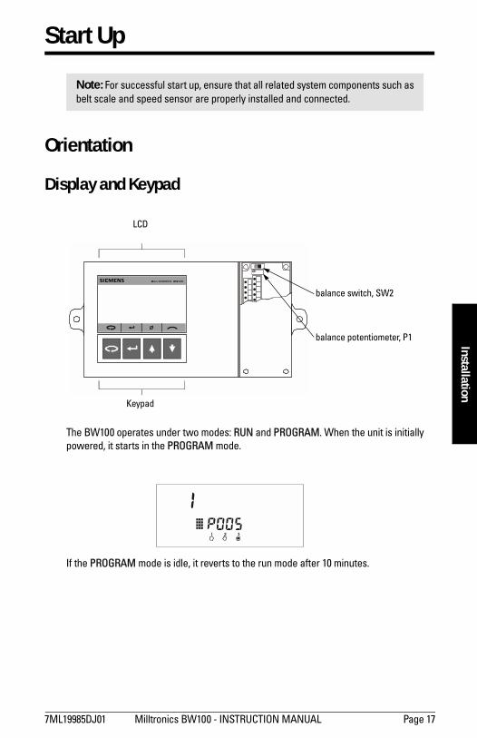
Orientation
Display and Keypad
The BW100 operates under two modes: RUN and PROGRAM. When the unit is initially powered, it starts in the PROGRAM mode.
If the PROGRAM mode is idle, it reverts to the run mode after 10 minutes.
Note: For successful start up, ensure that all related system components such as belt scale and speed sensor are properly installed and connected.
balance switch, SW2
balance potentiometer, P1
LCD
Keypad
1 2 3
Page 18 Milltronics BW100 - INSTRUCTION MANUAL 7ML19985DJ01
mm
mm
m
Star
t Up
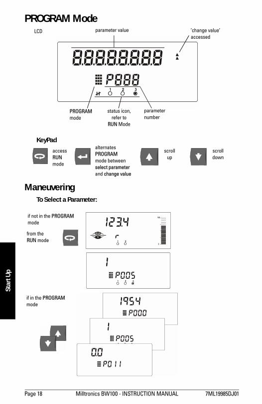
PROGRAM Mode
KeyPad
Maneuvering To Select a Parameter:
1 2 3
LCD parameter value change valueaccessed
parameternumber
status icon,refer to
RUN Mode
PROGRAMmode
accessRUNmode
scrolldown
scrollup
alternates PROGRAMmode betweenselect parameterand change value
1 2 3
1 2
if not in the PROGRAM mode
from theRUN mode
if in the PROGRAM mode
1 2 3
7ML19985DJ01 Milltronics BW100 - INSTRUCTION MANUAL Page 19
mm
mm
m
Start Up
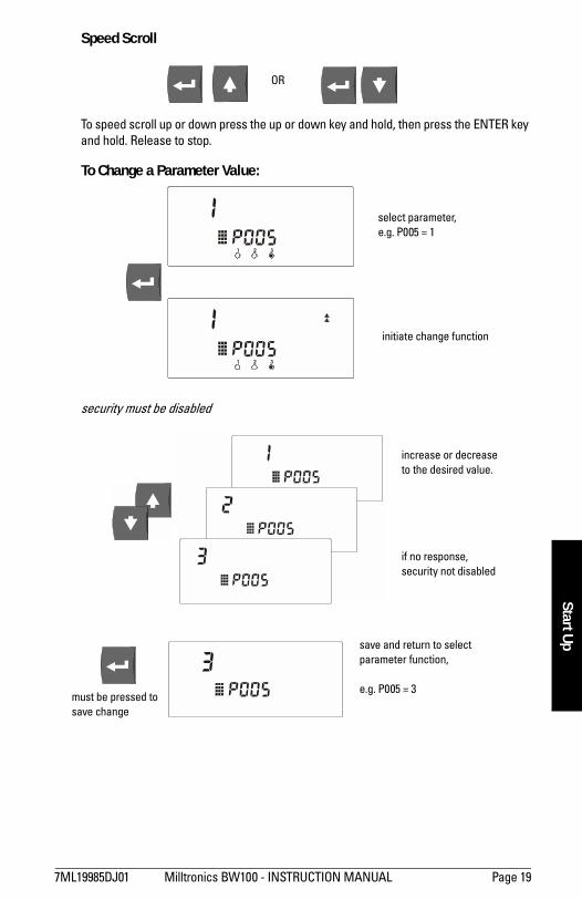
Speed Scroll
To speed scroll up or down press the up or down key and hold, then press the ENTER key and hold. Release to stop.
To Change a Parameter Value:
security must be disabled
OR
1 2 3
1 2 3
select parameter,e.g. P005 = 1
initiate change function
increase or decreaseto the desired value.
if no response,security not disabled
must be pressed tosave change
save and return to selectparameter function,
e.g. P005 = 3
Page 20 Milltronics BW100 - INSTRUCTION MANUAL 7ML19985DJ01
mm
mm
m
Star
t Up
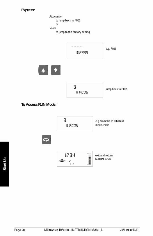
Express:
To Access RUN Mode:
e.g. P999
jump back to P005
Parameterto jump back to P005or
Valueto jump to the factory setting
1 2
e.g. from the PROGRAMmode, P005
exit and returnto RUN mode
7ML19985DJ01 Milltronics BW100 - INSTRUCTION MANUAL Page 21
mm
mm
m
Start Up
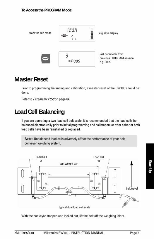
To Access the PROGRAM Mode:
Master ResetPrior to programming, balancing and calibration, a master reset of the BW100 should be done.
Refer to Parameter P999 on page 64.
Load Cell BalancingIf you are operating a two load cell belt scale, it is recommended that the load cells be balanced electronically prior to initial programming and calibration, or after either or both load cells have been reinstalled or replaced.
With the conveyor stopped and locked out, lift the belt off the weighing idlers.
Note: Unbalanced load cells adversely affect the performance of your belt conveyor weighing system.
1 2
e.g. rate display
last parameter fromprevious PROGRAM sessione.g. P005
from the run mode
test weight bar
Load CellB
belt travel
typical dual load cell scale
Load CellA
Page 22 Milltronics BW100 - INSTRUCTION MANUAL 7ML19985DJ01
mm
mm
m
Star
t Up
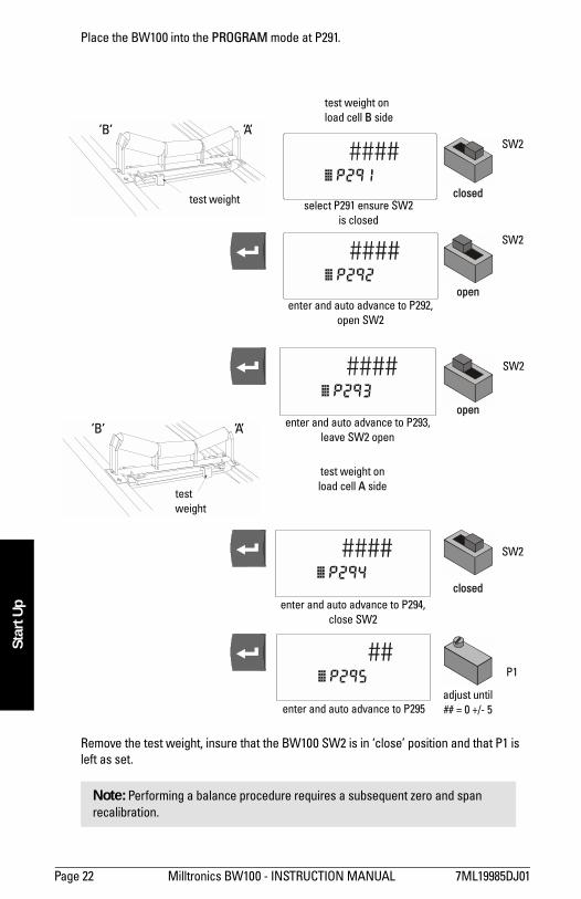
Place the BW100 into the PROGRAM mode at P291.
Remove the test weight, insure that the BW100 SW2 is in close position and that P1 is left as set.
Note: Performing a balance procedure requires a subsequent zero and span recalibration.
test weight
test weight
test weight onload cell B side
select P291 ensure SW2is closed
enter and auto advance to P292,open SW2
enter and auto advance to P293,leave SW2 open
test weight onload cell A side
SW2
SW2
SW2
SW2
P1
enter and auto advance to P294,close SW2
enter and auto advance to P295adjust until## = 0 +/- 5
closed
closed
open
open
B
B A
A
7ML19985DJ01 Milltronics BW100 - INSTRUCTION MANUAL Page 23
mm
mm
m
Start Up
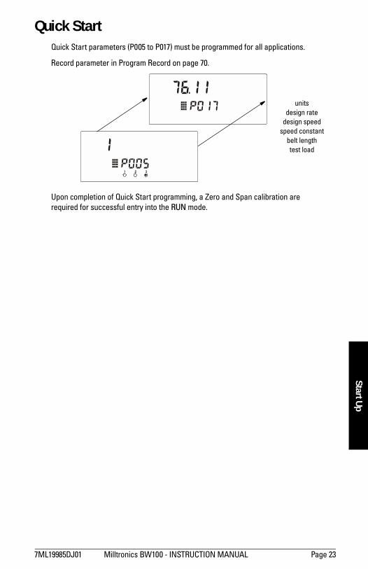
Quick Start Quick Start parameters (P005 to P017) must be programmed for all applications.
Upon completion of Quick Start programming, a Zero and Span calibration are required for successful entry into the RUN mode.
1 2 3
unitsdesign rate
design speedspeed constant
belt lengthtest load
Record parameter in Program Record on page 70.
Page 24 Milltronics BW100 - INSTRUCTION MANUAL 7ML19985DJ01
mm
mm
m
Star
t Up
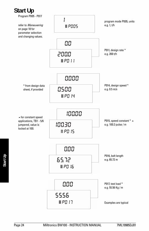
Start UpProgram P005 - P017
refer to Maneuvering on page 18 for parameter selection and changing values.
#for constant speedapplications, TB1 - 5/6jumpered, value islocked at 100.
* from design datasheet, if provided
P017, test load *e.g. 55.56 Kg / m
Examples are typical
P016, belt lengthe.g. 65.72 m
P015, speed constant * #e.g. 100.3 pulse / m
P014, design speed *e.g. 0.5 m/s
P011, design rate *e.g. 200 t/h
program mode P005, unitse.g. 1, t/h
7ML19985DJ01 Milltronics BW100 - INSTRUCTION MANUAL Page 25
mm
mm
m
Start Up
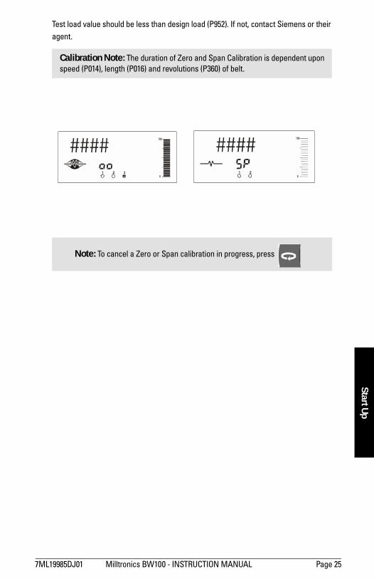
Test load value should be less than design load (P952). If not, contact Siemens or their agent.
Calibration Note: The duration of Zero and Span Calibration is dependent upon speed (P014), length (P016) and revolutions (P360) of belt.
Note: To cancel a Zero or Span calibration in progress, press
1 2 3 1 2
Page 26 Milltronics BW100 - INSTRUCTION MANUAL 7ML19985DJ01
mm
mm
m
Star
t Up
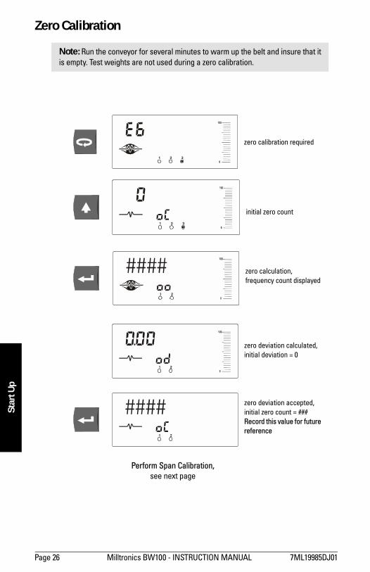
Zero Calibration
Note: Run the conveyor for several minutes to warm up the belt and insure that it is empty. Test weights are not used during a zero calibration.
1 2 3
1 2 3
1 2
1 2
1 2
zero calibration required
initial zero count
zero calculation,frequency count displayed
zero deviation calculated,initial deviation = 0
zero deviation accepted,initial zero count = ###Record this value for future reference
Perform Span Calibration,see next page
7ML19985DJ01 Milltronics BW100 - INSTRUCTION MANUAL Page 27
mm
mm
m
Start Up
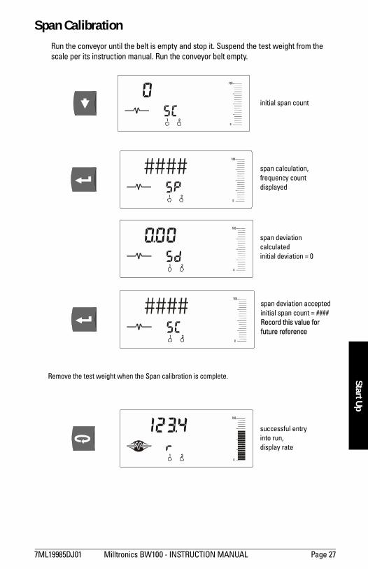
Span Calibration Run the conveyor until the belt is empty and stop it. Suspend the test weight from the scale per its instruction manual. Run the conveyor belt empty.
1 2
1 2
1 2
1 2
1 2
initial span count
Remove the test weight when the Span calibration is complete.
span calculation,frequency count displayed
span deviation calculatedinitial deviation = 0
span deviation acceptedinitial span count = ####Record this value for future reference
successful entry into run,display rate
Page 28 Milltronics BW100 - INSTRUCTION MANUAL 7ML19985DJ01
mm
mm
m
Star
t Up
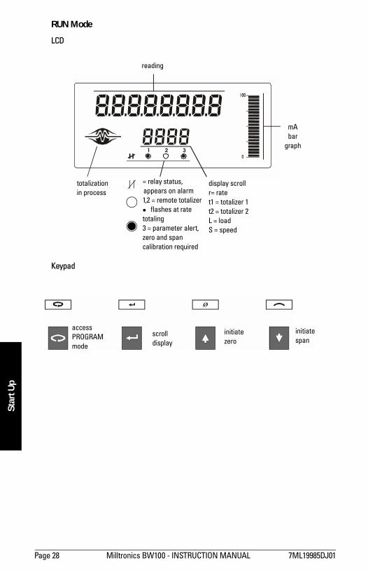
RUN Mode
LCD
Keypad
1 2 3
reading
totalizationin process
display scrollr= ratet1 = totalizer 1t2 = totalizer 2L = loadS = speed
mAbar
graph
= relay status,appears on alarm1,2 = remote totalizer$ flashes at rate totaling3 = parameter alert,zero and spancalibration required
accessPROGRAMmode
initiatezero
scrolldisplay
initiatespan
7ML19985DJ01 Milltronics BW100 - INSTRUCTION MANUAL Page 29
mm
mm
m
Start Up
Recalibration
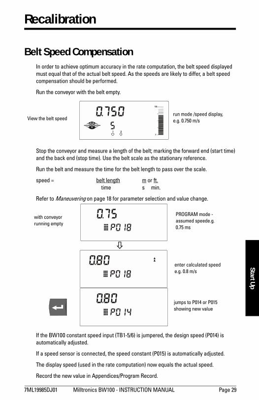
Belt Speed CompensationIn order to achieve optimum accuracy in the rate computation, the belt speed displayed must equal that of the actual belt speed. As the speeds are likely to differ, a belt speed compensation should be performed.
Run the conveyor with the belt empty.
Stop the conveyor and measure a length of the belt; marking the forward end (start time) and the back end (stop time). Use the belt scale as the stationary reference.
Run the belt and measure the time for the belt length to pass over the scale.
speed = belt length m or ft. time s min.
Refer to Maneuvering on page 18 for parameter selection and value change.
If the BW100 constant speed input (TB1-5/6) is jumpered, the design speed (P014) is automatically adjusted.
If a speed sensor is connected, the speed constant (P015) is automatically adjusted.
The display speed (used in the rate computation) now equals the actual speed.
Record the new value in Appendices/Program Record.
1 2
View the belt speedrun mode /speed display,e.g. 0.750 m/s
%
with conveyorrunning empty
jumps to P014 or P015showing new value
enter calculated speede.g. 0.8 m/s
PROGRAM mode -assumed speede.g. 0.75 ms
Page 30 Milltronics BW100 - INSTRUCTION MANUAL 7ML19985DJ01
mm
mm
m
Reca
libra
tion
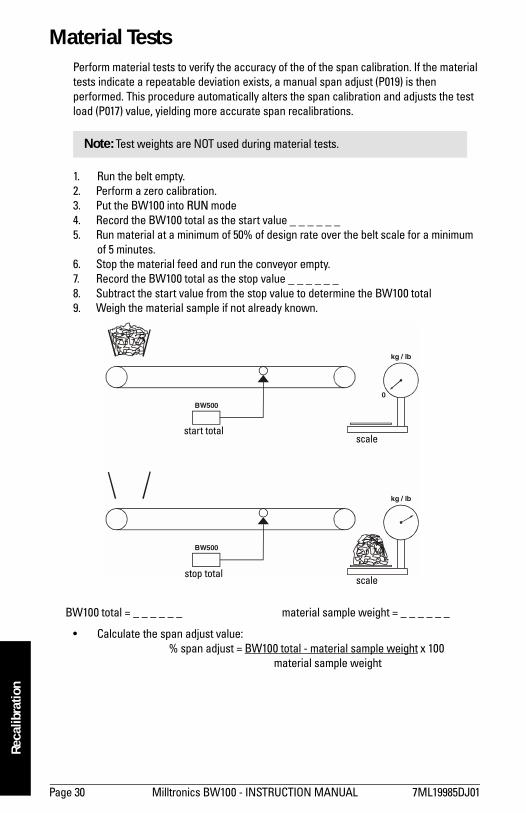
Material Tests Perform material tests to verify the accuracy of the of the span calibration. If the material tests indicate a repeatable deviation exists, a manual span adjust (P019) is then performed. This procedure automatically alters the span calibration and adjusts the test load (P017) value, yielding more accurate span recalibrations.
1. Run the belt empty. 2. Perform a zero calibration. 3. Put the BW100 into RUN mode 4. Record the BW100 total as the start value _ _ _ _ _ _ 5. Run material at a minimum of 50% of design rate over the belt scale for a minimum
of 5 minutes.6. Stop the material feed and run the conveyor empty. 7. Record the BW100 total as the stop value _ _ _ _ _ _ 8. Subtract the start value from the stop value to determine the BW100 total 9. Weigh the material sample if not already known.
Calculate the span adjust value: % span adjust = BW100 total - material sample weight x 100
material sample weight
Note: Test weights are NOT used during material tests.
0
kg / lb
kg / lb
BW500
BW500
BW100 total = _ _ _ _ _ _ material sample weight = _ _ _ _ _ _
start total
stop totalscale
scale
7ML19985DJ01 Milltronics BW100 - INSTRUCTION MANUAL Page 31
mm
mm
m
Recalibration
If the span adjust value is within the accuracy requirements of the weighing system, the material test was successful and normal operation can be resumed.
If the span adjust value is not acceptable, repeat the material test to verify repeatability. If the result of the second material test differs considerably, consult Milltronics or its agent.
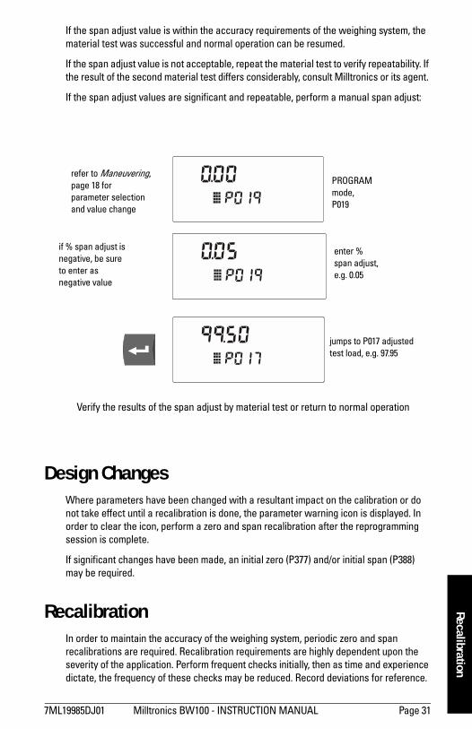
If the span adjust values are significant and repeatable, perform a manual span adjust:
Design Changes Where parameters have been changed with a resultant impact on the calibration or do not take effect until a recalibration is done, the parameter warning icon is displayed. In order to clear the icon, perform a zero and span recalibration after the reprogramming session is complete.
If significant changes have been made, an initial zero (P377) and/or initial span (P388) may be required.
RecalibrationIn order to maintain the accuracy of the weighing system, periodic zero and span recalibrations are required. Recalibration requirements are highly dependent upon the severity of the application. Perform frequent checks initially, then as time and experience dictate, the frequency of these checks may be reduced. Record deviations for reference.
PROGRAM mode,P019
enter % span adjust,e.g. 0.05
jumps to P017 adjustedtest load, e.g. 97.95
refer to Maneuvering, page 18 forparameter selectionand value change
if % span adjust isnegative, be sureto enter asnegative value
Verify the results of the span adjust by material test or return to normal operation
Page 32 Milltronics BW100 - INSTRUCTION MANUAL 7ML19985DJ01
mm
mm
m
Reca
libra
tion
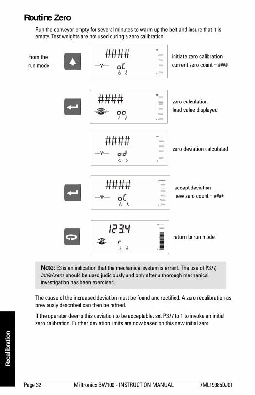
Routine Zero Run the conveyor empty for several minutes to warm up the belt and insure that it is empty. Test weights are not used during a zero calibration.
The cause of the increased deviation must be found and rectified. A zero recalibration as previously described can then be retried.
If the operator deems this deviation to be acceptable, set P377 to 1 to invoke an initial zero calibration. Further deviation limits are now based on this new initial zero.
Note: E3 is an indication that the mechanical system is errant. The use of P377, initial zero, should be used judiciously and only after a thorough mechanical investigation has been exercised.
1 2
1 2
1 2
1 2
initiate zero calibrationcurrent zero count = ####
zero calculation,load value displayed
zero deviation calculated
accept deviationnew zero count = ####
return to run mode
1 2
From therun mode
7ML19985DJ01 Milltronics BW100 - INSTRUCTION MANUAL Page 33
mm
mm
m
Recalibration
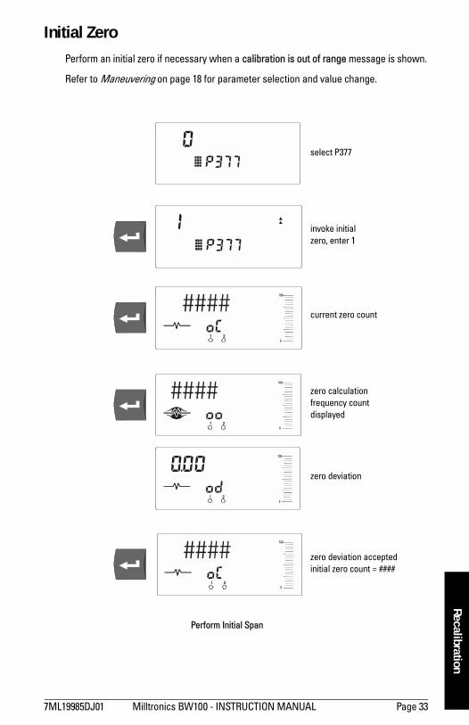
Initial ZeroPerform an initial zero if necessary when a calibration is out of range message is shown.
Refer to Maneuvering on page 18 for parameter selection and value change.
1 2
1 2
1 2
1 2
select P377
invoke initial zero, enter 1
current zero count
zero calculationfrequency count displayed
zero deviation
zero deviation acceptedinitial zero count = ####
Perform Initial Span
Page 34 Milltronics BW100 - INSTRUCTION MANUAL 7ML19985DJ01
mm
mm
m
Reca
libra
tion
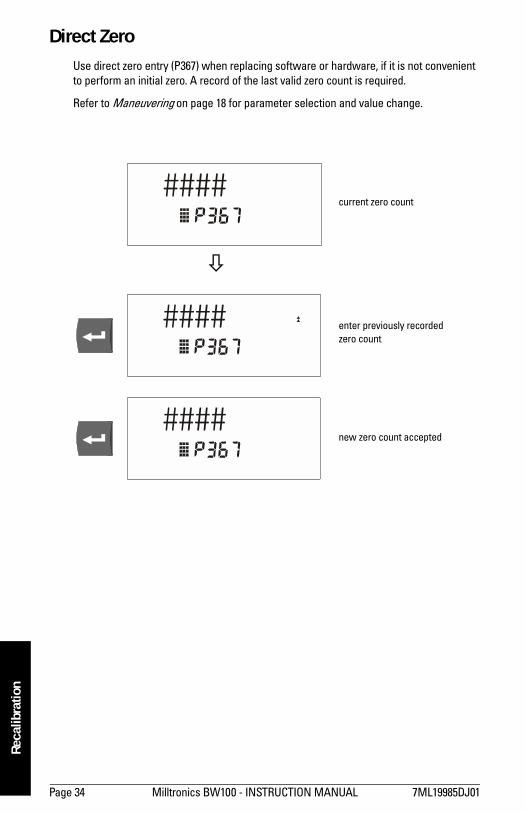
Direct Zero Use direct zero entry (P367) when replacing software or hardware, if it is not convenient to perform an initial zero. A record of the last valid zero count is required.
Refer to Maneuvering on page 18 for parameter selection and value change.
%
current zero count
enter previously recordedzero count
new zero count accepted
7ML19985DJ01 Milltronics BW100 - INSTRUCTION MANUAL Page 35
mm
mm
m
Recalibration
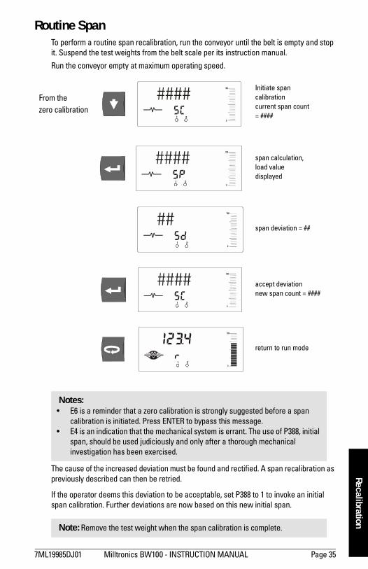
Routine Span To perform a routine span recalibration, run the conveyor until the belt is empty and stop it. Suspend the test weights from the belt scale per its instruction manual.
Run the conveyor empty at maximum operating speed.
The cause of the increased deviation must be found and rectified. A span recalibration as previously described can then be retried.
If the operator deems this deviation to be acceptable, set P388 to 1 to invoke an initial span calibration. Further deviations are now based on this new initial span.
Notes: E6 is a reminder that a zero calibration is strongly suggested before a span
calibration is initiated. Press ENTER to bypass this message. E4 is an indication that the mechanical system is errant. The use of P388, initial
span, should be used judiciously and only after a thorough mechanical investigation has been exercised.
Note: Remove the test weight when the span calibration is complete.
From the zero calibration
1 2
1 2
1 2
1 2
1 2
Initiate span calibrationcurrent span count = ####
span calculation,load value displayed
span deviation = ##
accept deviationnew span count = ####
return to run mode
Page 36 Milltronics BW100 - INSTRUCTION MANUAL 7ML19985DJ01
mm
mm
m
Reca
libra
tion
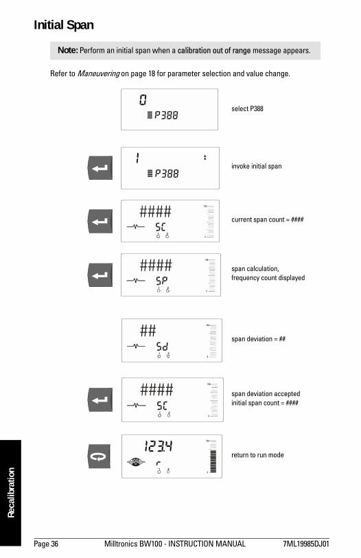
Initial Span
Refer to Maneuvering on page 18 for parameter selection and value change.
Note: Perform an initial span when a calibration out of range message appears.
1 2
1 2
1 2
1 2
1 2
select P388
span calculation,frequency count displayed
current span count = ####
invoke initial span
span deviation = ##
span deviation acceptedinitial span count = ####
return to run mode
7ML19985DJ01 Milltronics BW100 - INSTRUCTION MANUAL Page 37
mm
mm
m
Recalibration
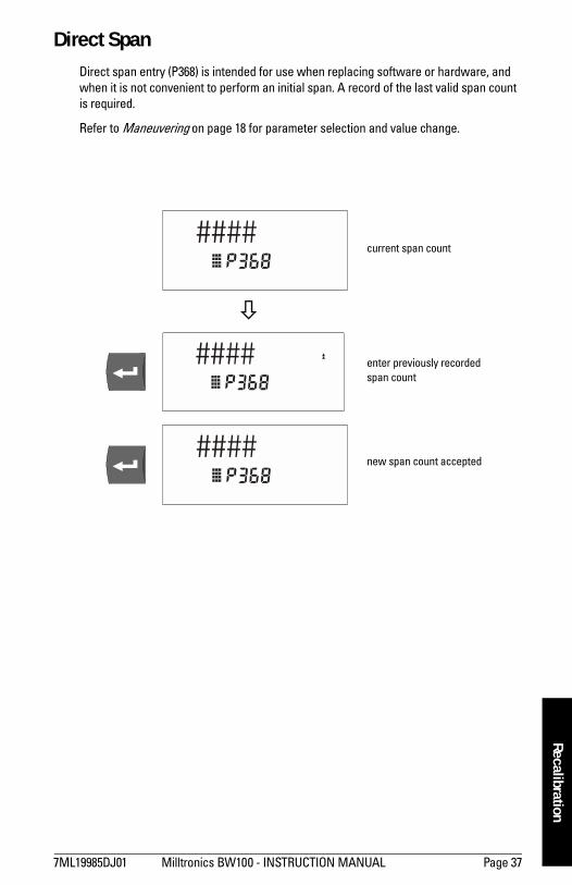
Direct Span Direct span entry (P368) is intended for use when replacing software or hardware, and when it is not convenient to perform an initial span. A record of the last valid span count is required.
Refer to Maneuvering on page 18 for parameter selection and value change.
%
current span count
enter previously recordedspan count
new span count accepted
Page 38 Milltronics BW100 - INSTRUCTION MANUAL 7ML19985DJ01
mm
mm
m
Reca
libra
tion
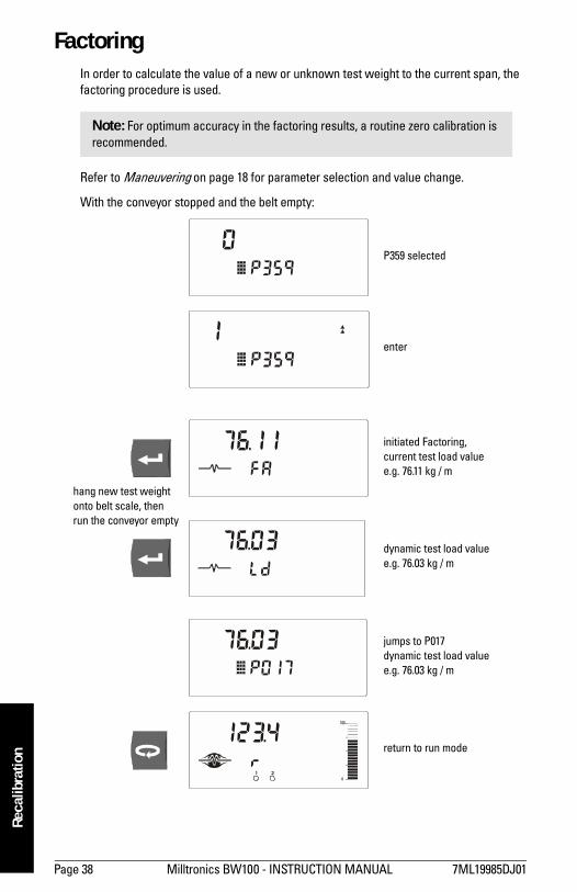
Factoring In order to calculate the value of a new or unknown test weight to the current span, the factoring procedure is used.
Refer to Maneuvering on page 18 for parameter selection and value change.
With the conveyor stopped and the belt empty:
Note: For optimum accuracy in the factoring results, a routine zero calibration is recommended.
1 2
hang new test weight onto belt scale, then run the conveyor empty
P359 selected
enter
initiated Factoring,current test load valuee.g. 76.11 kg / m
dynamic test load valuee.g. 76.03 kg / m
jumps to P017dynamic test load valuee.g. 76.03 kg / m
return to run mode
7ML19985DJ01 Milltronics BW100 - INSTRUCTION MANUAL Page 39
mm
mm
m
Recalibration
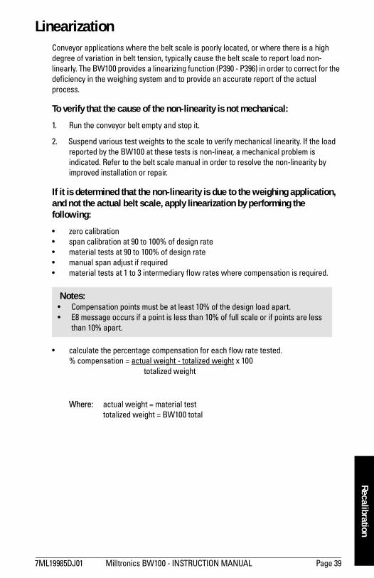
Linearization Conveyor applications where the belt scale is poorly located, or where there is a high degree of variation in belt tension, typically cause the belt scale to report load non-linearly. The BW100 provides a linearizing function (P390 - P396) in order to correct for the deficiency in the weighing system and to provide an accurate report of the actual process.
To verify that the cause of the non-linearity is not mechanical:
1. Run the conveyor belt empty and stop it.
2. Suspend various test weights to the scale to verify mechanical linearity. If the load reported by the BW100 at these tests is non-linear, a mechanical problem is indicated. Refer to the belt scale manual in order to resolve the non-linearity by improved installation or repair.
If it is determined that the non-linearity is due to the weighing application, and not the actual belt scale, apply linearization by performing the following:
zero calibration span calibration at 90 to 100% of design rate material tests at 90 to 100% of design rate manual span adjust if required material tests at 1 to 3 intermediary flow rates where compensation is required.
calculate the percentage compensation for each flow rate tested. % compensation = actual weight - totalized weight x 100
totalized weight
Where: actual weight = material testtotalized weight = BW100 total
Notes: Compensation points must be at least 10% of the design load apart. E8 message occurs if a point is less than 10% of full scale or if points are less
than 10% apart.
Page 40 Milltronics BW100 - INSTRUCTION MANUAL 7ML19985DJ01
mm
mm
m
Reca
libra
tion
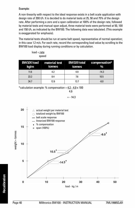
Example:
A non-linearity with respect to the ideal response exists in a belt scale application with design rate of 200 t/h. It is decided to do material tests at 25, 50 and 75% of the design rate. After performing a zero and a span calibration at 100% of the design rate, followed by material tests and manual span adjust, three material tests were performed at 50, 100 and 150 t/h, as indicated by the BW100. The following data was tabulated. (This example is exaggerated for emphasis).
The material tests should be run at same belt speed, representative of normal operation; in this case 1.2 m/s. For each rate, record the corresponding load value by scrolling to the BW100 load display during running conditions or by calculation.
load = ratespeed
*calculation example: % compensation = 4.2 - 4.9 x 100 4.9
= - 14.3
BW100 loadkg/m
material testtonnes
BW100 totaltonnes
compensation*%
11.6 4.2 4.9 -14.3
23.2 8.4 7.6 10.5
34.7 12.6 13.7 -8.0
5
10
15
20
0 10
-14.0
10.5
-8.0
20 30 40 50
load - kg / m
wei
ght =
tonn
es
actual weight per material testtotalized weight by BW100belt scale responselinearized BW100 response% compensationspan (100%)
3
7ML19985DJ01 Milltronics BW100 - INSTRUCTION MANUAL Page 41
mm
mm
m
Recalibration
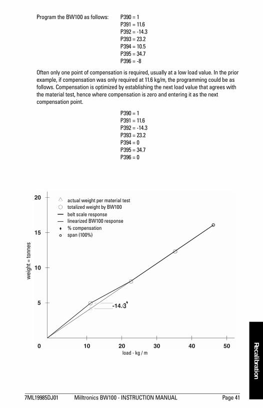
Program the BW100 as follows: P390 = 1 P391 = 11.6 P392 = -14.3P393 = 23.2 P394 = 10.5 P395 = 34.7 P396 = -8
Often only one point of compensation is required, usually at a low load value. In the prior example, if compensation was only required at 11.6 kg/m, the programming could be as follows. Compensation is optimized by establishing the next load value that agrees with the material test, hence where compensation is zero and entering it as the next compensation point.
P390 = 1 P391 = 11.6 P392 = -14.3 P393 = 23.2 P394 = 0 P395 = 34.7 P396 = 0
5
10
15
20
0 10
-14.0
20 30 40 50load - kg / m
wei
ght =
tonn
es
actual weight per material testtotalized weight by BW100belt scale responselinearized BW100 response% compensationspan (100%)
3
Page 42 Milltronics BW100 - INSTRUCTION MANUAL 7ML19985DJ01
mm
mm
m
Reca
libra
tion
Operation
Load SensingIn order for the BW100 to calculate rate and hence totalize material flow along the belt conveyor, a load signal representative of weight of material on the belt is required. The load signal is provided by the belt scale. The BW100 is compatible with belt scales fitted with one or two strain gauge type load cells.
Refer to Specifications on page 3 and Installation/Load Cell on page 6 for belt scale requirements and connection.
Speed SensingIn order for the BW100 to calculate rate and hence totalize material flow along the belt conveyor, a speed signal representative of belt speed is required. In constant speed applications (no speed sensor), the BW100 can be programmed to provide an internal speed signal. This is achieved by entering the design speed (P014) and providing a jumper across speed input terminals (TB1-5/6). Speed constant (P015) defaults to 100.
For optimum accuracy of the weighing system, both constant and variable speed applications, a speed sensor is required. Again, the design speed and speed constants need to be programmed, however the jumper across the speed input has to be removed and the speed sensor connected.
Refer to Specifications on page 3 and Installation/Speed Sensor on page 6 for speed sensor requirements and connection.
Modes of Operation RUN is the normal or reference mode of operation. It continuously processes the load signal from the belt scale to produce internal load and rate signals, which are in turn used as the basis for totalization, mA output and relay control. The RUN display is programmed (P081) to scroll through rate, totalization, load and speed; either manually by pressing the ENTER key, or automatically. A bar graph is continuously displayed. It is proportional to the analog output as programmed (see Analog Output on page 43).
From the RUN mode, access to the PROGRAM mode on and zero and span calibration is made.
The PROGRAM mode allows viewing and, with security permission (P000), changing parameter values. During PROGRAM, RUN mode functions are still active, i.e.: rate, relay, analog output and totalization. Error interrupts are suppressed and the bar graph is disabled.
If the PROGRAM mode is left idle for a period of ten minutes, it automatically reverts to the RUN mode.
7ML19985DJ01 Milltronics BW100 - INSTRUCTION MANUAL Page 43
mm
mm
m
Operation
Damping Damping (P080) controls the speed at which the displayed readings and output functions respond to changes in their respective input function; load, speed and the internal rate signals. Changes in the displayed rate of material flow, material loading and belt speed are controlled by the damping. Relay alarm functions based on input functions of flow, load and speed, respond to the damped value.
If the specific mA output damping parameter (P220) is enabled (value other than 0), then the damping (P080) as it pertains to the mA function is overridden, and the output value and bar graph respond independently at the specified mA output damping rate (P220).
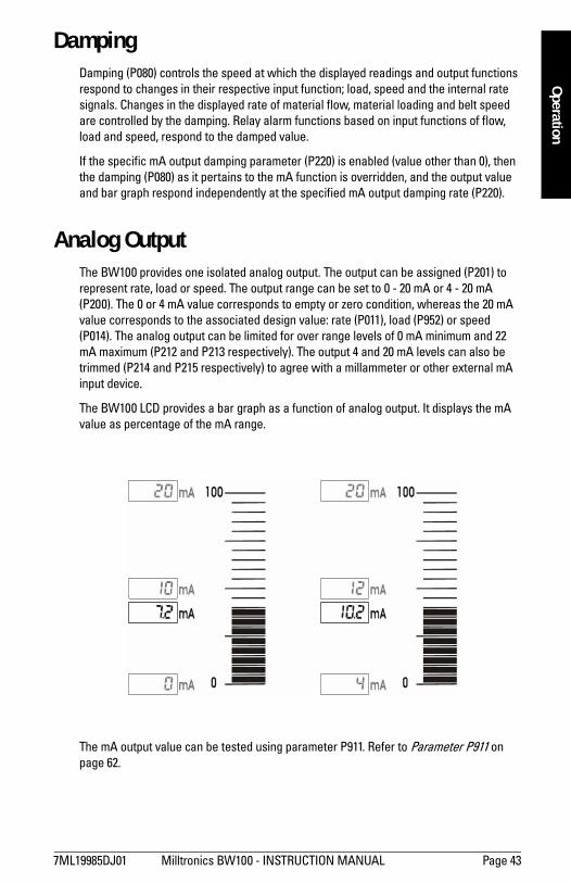
Analog Output The BW100 provides one isolated analog output. The output can be assigned (P201) to represent rate, load or speed. The output range can be set to 0 - 20 mA or 4 - 20 mA (P200). The 0 or 4 mA value corresponds to empty or zero condition, whereas the 20 mA value corresponds to the associated design value: rate (P011), load (P952) or speed (P014). The analog output can be limited for over range levels of 0 mA minimum and 22 mA maximum (P212 and P213 respectively). The output 4 and 20 mA levels can also be trimmed (P214 and P215 respectively) to agree with a millammeter or other external mA input device.
The BW100 LCD provides a bar graph as a function of analog output. It displays the mA value as percentage of the mA range.
The mA output value can be tested using parameter P911. Refer to Parameter P911 on page 62.
Page 44 Milltronics BW100 - INSTRUCTION MANUAL 7ML19985DJ01
mm
mm
m
Ope
ratio
n
Relay Output The BW100 offers one single pole double throw (SPDT) relay that can be assigned (P100) to one of the following alarm functions:
rate: relay alarms on high and/or low material flow rate. auto zero: relay alarms when an attempted auto zero calibration reports an out of
range condition (E9). speed: relay alarms on high and/or low belt speed. load: relay alarms on high and or low belt load. error: relay alarms on any error condition as it is reported.
Refer to Troubleshooting, page 65.
Except for alarm on auto zero and error, the high and low alarm setpoints (P101 and P102 respectively) are required and must be entered in the appropriate units.
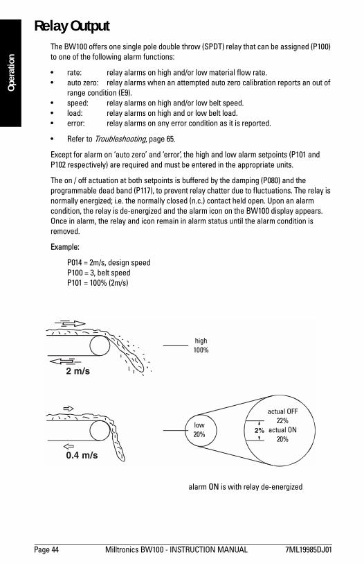
The on / off actuation at both setpoints is buffered by the damping (P080) and the programmable dead band (P117), to prevent relay chatter due to fluctuations. The relay is normally energized; i.e. the normally closed (n.c.) contact held open. Upon an alarm condition, the relay is de-energized and the alarm icon on the BW100 display appears. Once in alarm, the relay and icon remain in alarm status until the alarm condition is removed.
Example:
P014 = 2m/s, design speed P100 = 3, belt speed P101 = 100% (2m/s)
2 m/s
2%
0.4 m/s
high100%
low20%
actual OFF22%
actual ON20%
alarm ON is with relay de-energized
7ML19985DJ01 Milltronics BW100 - INSTRUCTION MANUAL Page 45
mm
mm
m
Operation
Totalization The totalization function is based on the internal rate (mass per unit time) signal proportional to belt speed and load on the associated belt scale. It is not affected by the damping function (P080). The rate signal is sampled several times a second to accurately count the mass of material conveyed. The count is held in the master totalizer used to increment the internal totalizers and to produce a pulse signal for the remote totalizers.
The BW100 provides four separate totalizer functions:
internal totalizer 1 internal totalizer 2 remote totalizer 1 remote totalizer 2
To avoid totalizing material at low flow rates, the totalizer drop out limit (P619) is set to a percentage of the design rate. Below this limit, totalization stops. When material flow returns to a rate above the drop out limit, totalization resumes.
Totalizer resolution or count value is set by the respective control parameters, P631 --P639. If the resolution selected causes the totalizer to lag behind the count rate, an E2 error is displayed after making the parameter entry. The error is rectified by selecting a greater resolution value.
Example: Internal totalizer 1
Given: P005 = 1 (t/h)P631 = 4
Then: totalizer count increments by 10 for each 10 metric tonnes registered
External totalizer 1
Given: P005 = 1 (t/h)P638 = 5
Then: contact closure occurs once for every 10 metric tonnes registered
For remote totalization, the contact closure duration is set by the respective control parameters, P643 and P644. The value is automatically calculated upon entry of the design rate (P011) and remote totalizer parameters (P638 and P639), so that the duration of contact closure allows the relay response to track the total up to the design rate. The value can be changed to suit specific contact closure requirements, such as in the case of programmable logic controllers. If an E2 error is displayed, P638 or P639 has to be increased.
The totalizers are reset through the master reset (P999), the totalizer reset (P648) or through the keypad.
master reset: the reset of all totalizer functions is included in the master reset. totalizer reset: totalizer reset can be used to resets internal totalizers 1 and 2, or
totalizer 2 independently.
keypad: pressing simultaneously while in the RUN mode resets internal totalizer 1, as well as the internal counts for both remote totalizers.

Page 46 Milltronics BW100 - INSTRUCTION MANUAL 7ML19985DJ01
mm
mm
m
Ope
ratio
nPlacing the internal totalizers on to the display scroll of the RUN mode is controlled by the totalizer display parameter (P647); displaying either one or both totalizers.
Auto Zero The Auto Zero function allows a zero calibration to be initiated automatically under the following conditions.
the auto zero input (TB1-9/10) is in a closed state; jumper or remote switch
the load is less than 2% of the design load
If the resulting zero deviation is less than an accumulated 2% from the last operator initiated zero, the auto zero is accepted.
If the deviation is greater than an accumulated 2%, an E9 error is displayed and the relay, if so programmed, goes into alarm (refer to Operation/Relay Output, page 44). The E9 error is cleared after five seconds.
If material feed resumes during an auto zero function, the totalizing function is maintained.
7ML19985DJ01 Milltronics BW100 - INSTRUCTION MANUAL Page 47
mm
mm
m
Operation
Communications
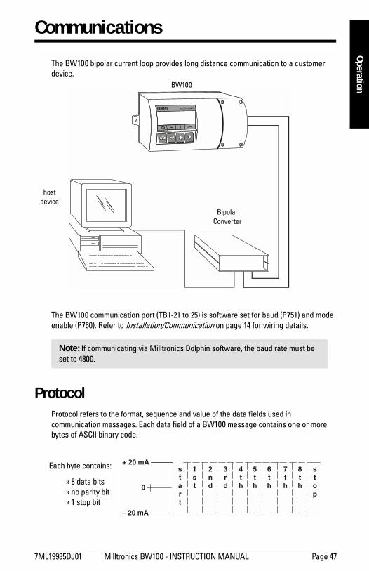
The BW100 bipolar current loop provides long distance communication to a customer device.
The BW100 communication port (TB1-21 to 25) is software set for baud (P751) and mode enable (P760). Refer to Installation/Communication on page 14 for wiring details.
Protocol Protocol refers to the format, sequence and value of the data fields used in communication messages. Each data field of a BW100 message contains one or more bytes of ASCII binary code.
Note: If communicating via Milltronics Dolphin software, the baud rate must be set to 4800.
BW100
hostdevice
Bipolar Converter
Each byte contains:
» 8 data bits » no parity bit » 1 stop bit
0
– 20 mA
+ 20 mAstart
1st
2nd
3rd
4th
5th
6th
7th
8th
stop
Page 48 Milltronics BW100 - INSTRUCTION MANUAL 7ML19985DJ01
mm
mm
m
Com
mun
icat
ions
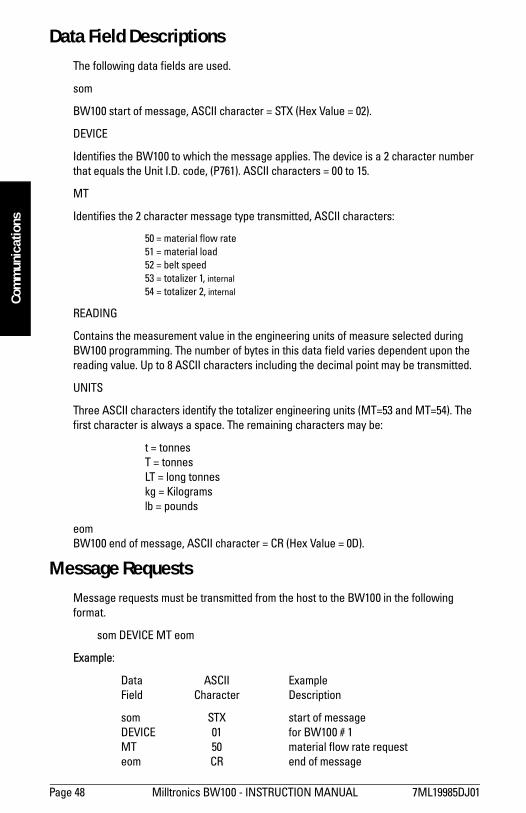
Data Field Descriptions The following data fields are used.
som
BW100 start of message, ASCII character = STX (Hex Value = 02).
DEVICE
Identifies the BW100 to which the message applies. The device is a 2 character number that equals the Unit I.D. code, (P761). ASCII characters = 00 to 15.
MT
Identifies the 2 character message type transmitted, ASCII characters:
50 = material flow rate 51 = material load 52 = belt speed 53 = totalizer 1, internal 54 = totalizer 2, internal
READING
Contains the measurement value in the engineering units of measure selected during BW100 programming. The number of bytes in this data field varies dependent upon the reading value. Up to 8 ASCII characters including the decimal point may be transmitted.
UNITS
Three ASCII characters identify the totalizer engineering units (MT=53 and MT=54). The first character is always a space. The remaining characters may be:
t = tonnes T = tonnes LT = long tonnes kg = Kilograms lb = pounds
eom BW100 end of message, ASCII character = CR (Hex Value = 0D).
Message RequestsMessage requests must be transmitted from the host to the BW100 in the following format.
som DEVICE MT eom
Example:
Data ASCII Example Field Character Description
som STX start of message DEVICE 01 for BW100 # 1 MT 50 material flow rate request eom CR end of message
7ML19985DJ01 Milltronics BW100 - INSTRUCTION MANUAL Page 49
mm
mm
m
Comm
unications
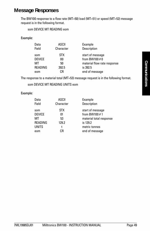
Message Responses The BW100 response to a flow rate (MT=50) load (MT=51) or speed (MT=52) message request is in the following format.
som DEVICE MT READING eom
Example:
Data ASCII Example Field Character Description
som STX start of message DEVICE 00 from BW100 # 0 MT 50 material flow rate response READING 392.5 is 392.5 eom CR end of message
The response to a material total (MT=53) message request is in the following format.
som DEVICE MT READING UNITS eom
Example:
Data ASCII Example Field Character Description
som STX start of message DEVICE 01 from BW100 # 1 MT 53 material total response READING 129.2 is 129.2 UNITS t metric tonnes eom CR end of message
Page 50 Milltronics BW100 - INSTRUCTION MANUAL 7ML19985DJ01
mm
mm
m
Com
mun
icat
ions
Parameters
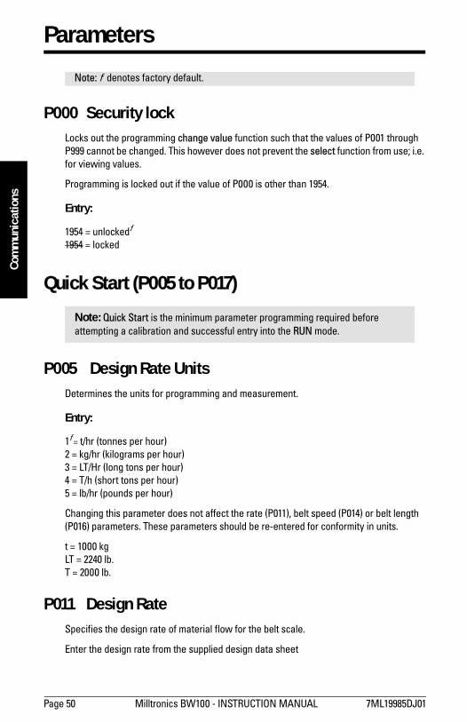
P000 Security lock Locks out the programming change value function such that the values of P001 through P999 cannot be changed. This however does not prevent the select function from use; i.e. for viewing values.
Programming is locked out if the value of P000 is other than 1954.
Entry:
1954 = unlockedf
1954 = locked
Quick Start (P005 to P017)
P005 Design Rate Units Determines the units for programming and measurement.
Entry:
1f = t/hr (tonnes per hour)2 = kg/hr (kilograms per hour)3 = LT/Hr (long tons per hour)4 = T/h (short tons per hour)5 = lb/hr (pounds per hour)
Changing this parameter does not affect the rate (P011), belt speed (P014) or belt length (P016) parameters. These parameters should be re-entered for conformity in units.
t = 1000 kg LT = 2240 lb. T = 2000 lb.
P011 Design Rate Specifies the design rate of material flow for the belt scale.
Enter the design rate from the supplied design data sheet
Note: f denotes factory default.
Note: Quick Start is the minimum parameter programming required before attempting a calibration and successful entry into the RUN mode.
7ML19985DJ01 Milltronics BW100 - INSTRUCTION MANUAL Page 51
mm
mm
m
Parameters
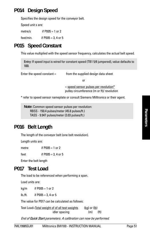
P014 Design Speed Specifies the design speed for the conveyor belt.
Speed unit s are:
metre/s if P005 = 1 or 2
feet/min. if P005 = 3, 4 or 5
P015 Speed Constant This value multiplied with the speed sensor frequency, calculates the actual belt speed.
Enter the speed constant = from the supplied design data sheet
or
= speed sensor pulses per revolution* pulley circumference (m or ft)/ revolution
* refer to speed sensor nameplate or consult Siemens Milltronics or their agent.
P016 Belt Length The length of the conveyor belt (one belt revolution).
Length units are:
metre if P005 = 1 or 2
feet if P005 = 3, 4 or 5
Enter the belt length
P017 Test Load The load to be referenced when performing a span.
Load units are:
kg/m if P005 = 1 or 2
lb./ft. if P005 = 3, 4 or 5
The value for P017 can be calculated as follows:
Test Load=Total weight of of all test weights (kg) or (lb) idler spacing (m) (ft)
End of Quick Start parameters. A calibration can now be performed.
Entry: If speed input is wired for constant speed (TB1 5/6 jumpered), value defaults to 100.
Note: Common speed sensor pulses per revolution:RBSS - 150.4 pulses/meter (45.8 pulses/ft.)TASS - 9.947 pulses/meter (3.03 pulses/ft.)
Page 52 Milltronics BW100 - INSTRUCTION MANUAL 7ML19985DJ01
mm
mm
m
Para
met
ers
P018 Speed Constant Adjust This parameter allows adjustment to the speed constant (P015).
Initially, this parameter displays the dynamic speed of the belt. If the displayed speed is not equal to the actual speed, enter the actual belt speed.
For speed sensor applications, the value of P015 is automatically adjusted.
For constant speed (TB1 5/6 jumper) the value of P014 is automatically adjusted.
P019 Manual Span Adjust This parameter allows adjustment to the span calibration.
The adjustment value is generally determined by performing material tests. Refer to Recalibration/Material Tests, page 30.
Enter the calculated adjustment.
P022 Minimum Speed Frequency Sets the minimum frequency that the speed sensor can reliably read. Signals at low frequencies are erratic, adversely affecting the performance of the weighing system.
Entry:
1 = 1 Hz (at 1 Hz, it takes 1 sec before defaulting to 0 speed)2 = 2 Hz (at 2 Hz, it takes 0.5 sec before defaulting to 0 speed)
P080 Damping Sets the speed of response to which the displayed readings (rate, load and speed), and outputs (alarm and mA) react to change.
The greater the damping value, the slower the response.
Enter damping value, range 1 - 9999.
P081 Display Mode Sets the display mode. Normally, the display shows rate, or the last manually selected function. If set to alternating, the display alternates between rate and totalizer (1 and/or 2, as programmed by P647).
Entry:
0 = normal 1 = alternating
Note: The effect of damping (P080) on mA output can be overridden by mA output damping (P220).
7ML19985DJ01 Milltronics BW100 - INSTRUCTION MANUAL Page 53
mm
mm
m
Parameters
Relay/Alarm Function (P100 - P117)
P100 Relay Set Up Sets the alarm mode for the relay.
Entry:
0 = off 1 = rate 2 = auto zero 3 = belt speed 4 = belt load 5 = error
P101 High Alarm Sets the high alarm setpoint for relay functions P100 = 1, 3 or 4.
Enter the value in % of full scale.
P102 Low Alarm Sets the low alarm setpoint for relay functions P100 = 1, 3 or 4.
Enter the value in % of full scale.
P117 Alarm Dead Band Sets the dead band to prevent relay chatter due to fluctuations at the high or low setpoint.
Enter the value in % of full scale
End of relay/alarm parameters.
mA Output Parameters (P200 - P220)
Note: These parameter are specific to the use of the relay/alarm function. Refer to Operation/Relay Output, page 13.
Note: These parameters are specific to the use of the mA output. Refer to Operation on page 42 for details.
Page 54 Milltronics BW100 - INSTRUCTION MANUAL 7ML19985DJ01
mm
mm
m
Para
met
ers
P200 mA Range Sets the range for the mA output.
Entry:
1 = 0 - 20 mA 2 = 4 - 20 mA
P201 mA Function Assigns the mA output to track one of the integrator functions.
Entry:
1 = rate 2 = load 3 = speed
P212 mA Min Limit Limits the lower mA range (0 or 4 mA) to a minimum output value.
Enter limit value, range 0 - 22.
P213 mA Max Limit Limits the upper mA range (20 mA) to a maximum output value.
Enter limit value, range 0 - 22.
P214 4 mA Trim Adjusts the 4 mA output level to agree with a milliammeter or other external mA input device.
Enter trim value, range 0 - 9999.
P215 20 mA Trim Adjusts the 20 mA output level to agree with a milliammeter or other external mA input device.
Enter trim value, range 0 - 9999
P220 mA Output Damping Sets the speed at which the mA output reacts to change.
The greater the damping value, the slower the response. If the value is 0, the mA output assumes the damping set in P080.
Enter the damping value, range 0 - 9999
End of mA output parameters.
7ML19985DJ01 Milltronics BW100 - INSTRUCTION MANUAL Page 55
mm
mm
m
Parameters
Load Cell Balancing Parameters (P291 - P295)
P291 Calculator Input 1 This register displays the count associated with the summation of load cell A and B signals, when balancing the A and B load cells of the associated belt scale.
P292 Calculator Input 2 This register displays the count associated with the load B signal, when balancing the A and B load cells of the associated belt scale.
P293 Calculator Input 3 This register displays the count associated with the load cell B signal, when balancing the A and B load cells of the associated belt scale.
P294 Calculator Input 4 This register displays the count associated with the summation of load cell A and B signals, when balancing the A and B load cells of the associated belt scale.
P295 Load Cell Balance Used in conjunction with balance calculator parameters (P291 - P 294), this parameter displays the adjustment required to complete the load cell balance procedure.
End of balancing parameters
P341 Run Time The cumulative days that the application device has been in service. The time is recorded once daily in a non-resetable counter. Periods of less than 24 hr. are not recorded, nor accumulated.
Note: These parameters are used for verifying or balancing the load cells (2) on the associated conveyor belt scale. Refer to Start Up, page 17, for details and procedure for use of these parameters.

Page 56 Milltronics BW100 - INSTRUCTION MANUAL 7ML19985DJ01
mm
mm
m
Para
met
ers
P350 Calibration Security This parameter provides additional security to the global lock (P000).
Entry:
0 = view parameters, perform zero and span, no reset of totalizer 1 1 = same as level 0, but cannot perform span 2 = same as level 0, but cannot perform zero and span
P359 Factoring Factoring is used as a method of calculating the value of the test load (P017) to a new physical test weight.
Entry:
0 = idle 1 = factor
P360 Calibration Duration Sets the number of belt revolutions to use during a zero or span calibration.
Enter number of belt revolutions, range 1 - 99.
P367 Direct Zero This parameter allows the zero reference count to be viewed or entered directly.
Direct entry is intended for use when replacing software or hardware and it is not convenient to perform an initial zero at that time.
P368 Direct Span This parameter allows the span reference count to be viewed or entered directly.
Direct entry is intended for use when replacing software or hardware and it is not convenient to perform an initial span at that time.
P370 Zero Limit Sets the zero calibration deviation limit from the last initial zero. If the accumulated deviation exceeds the limit, the zero calibration is aborted (E3).
Entry:
0 = +/- 12.5% of initial zero 1 = +/- 2% of initial zero
Note: Totalization is halted during the factoring procedure, and resumed only upon return to the RUN mode.
7ML19985DJ01 Milltronics BW100 - INSTRUCTION MANUAL Page 57
mm
mm
m
Parameters
P377 Initial Zero The initial zero is the reference zero to which all subsequent operator initiated zero calibrations are compared in determining whether they have deviated beyond the zero limit (P370).
Entry:
0 = idle 1 = initial zero
P388 Initial Span The initial span is the reference to which all subsequent span calibrations are compared in determining whether they have deviated beyond 12.5% of the initial span.
Entry:
0 = idle 1 = initial span
Linearization Parameters (P390 - P396)
P390 Linearization Enables or disables the linearization function.
Entry:
0 = OFF1 = ON
P391 Linearizer, Point 1 Enter the load, in units of P017, for point 1
P392 Compensation, Point 1 Enter the calculated compensation, in percent, for compensation point 1
Note: Refer to Recalibration/Initial Zero on page 33 for use of this function.
Note: Refer to Recalibration/Initial Span on page 36 for use of this function.
Note: These parameters are used to compensate for non-linear response of the weighing system to the BW100. Refer to Recalibration/Linearization for details and example on the use of these parameters.
Page 58 Milltronics BW100 - INSTRUCTION MANUAL 7ML19985DJ01
mm
mm
m
Para
met
ers
P393 Linearizer, Point 2 Enter the load, in units of P017, for point 2.
P394 Compensation, Point 2 Enter the calculated compensation, in percent, for compensation point 2.
P395 Linearizer, Point 3 Enter the load, in units of P017, for point 3.
P396 Compensation, Point 3 Enter the calculated compensation, in percent, for compensation point 3.
End of Linearization Parameters.
Totalization (P619 - P648) The following parameters are specific to the use to the BW100 totalizers. Refer also to Operation/Totalization, page 45.
Select a greater resolution value.
Example
Given: P005 = 1 (t/h) P631 = 5
Then: totalizer count increments by 10 for each 10 metric tonne registered
P619 Totalizer Drop Out This parameter sets the limit, in percent of design rate, below which material rates are not totalized.
The value of 0 is reserved to allow both negative and positive totalization.
Enter drop out value in % of design rate.
Note: If the resolution (P631 - P639) selected would cause the totalizer to lag behind the count rate, a message E2 is displayed after making the entry.
7ML19985DJ01 Milltronics BW100 - INSTRUCTION MANUAL Page 59
mm
mm
m
Parameters
P631 Totalizer 1 Resolution, Internal This parameter sets the resolution of internal totalizer 1.
Entry:
1 = 0.001 (one thousandth) 2 = 0.01 (one hundredth) 3 = 0.1 (one tenth) 4 = 1 (unit) 5 = 10 (x ten) 6 = 100 (x hundred) 7 = 1000 (x thousand)
P632 Totalizer 2 Resolution, Internal This parameter sets the resolution of internal totalizer 2.
Entry:
1 = 0.001 (one thousandth) 2 = 0.01 (one hundredth) 3 = 0.1 (one tenth) 4 = 1 (unit) 5 = 10 (x ten) 6 = 100 (x hundred) 7 = 1000 (x thousand)
P638 Totalizer 1 Resolution, External This parameter sets the resolution of external totalizer 1.
Entry:
1 = 0.001 (one thousandth) 2 = 0.01 (one hundredth) 3 = 0.1 (one tenth) 4 = 1 (unit) 5 = 10 (x ten) 6 = 100 (x hundred) 7 = 1000 (x thousand)
P639 Totalizer 2 Resolution, External This parameter sets the resolution of external totalizer 2.
Entry:
1 = 0.001 (one thousandth) 2 = 0.01 (one hundredth) 3 = 0.1 (one tenth) 4 = 1 (unit) 5 = 10 (x ten) 6 = 100 (x hundred) 7 = 1000 (x thousand)
Page 60 Milltronics BW100 - INSTRUCTION MANUAL 7ML19985DJ01
mm
mm
m
Para
met
ers
P643 Totalizer 1 Contact Closure, External The value of this parameter represents a multiple of 32 ms of contact closure for remote totalizer 1. The value is automatically calculated upon entry of P1 (design rate) and P638 (totalizer 1 resolution, external) so that the duration of contact closure allows the transistor switch response to track the total, up to the design rate.
The value can be changed to suit specific contact closure requirements, such as in the case of programmable logic controllers. If a message E2 is displayed, P638 has to be increased.
Entry:
1 = 32 ms2 = 64 3 = 96 4 = 128 5 = 160 6 = 1927 = 2248 = 2569 = 288
P644 Totalizer 2 Contact Closure, External The value of this parameter represents a multiple of 32 ms of contact closure for remote totalizer 2. The value is automatically calculated upon entry of P1 (design rate) and P639 (totalizer 2 resolution, external) so that the duration of contact closure allows the transistor switch response to track the total, up to the design rate.
The value can be changed to suit specific contact closure requirements, such as in the case of programmable logic controllers. If a message E2 is displayed, P639 has to be increased.
Entry:
1 = 32 ms 6 = 192 2 = 64 7 = 224 3 = 96 8 = 256 4 = 128 9 = 288 5 = 160
P647 Totalizer Display Selects the totalizer combination to be displayed, either manually through the scroll display key or automatically by control of the display mode (P081).
Entry:
1 = totalizer 1 2 = totalizer 2 3 = totalizers 1 and 2
7ML19985DJ01 Milltronics BW100 - INSTRUCTION MANUAL Page 61
mm
mm
m
Parameters
P648 Totalizer Reset, Internal Resets the internal totalizers.
Entry:
0 = idle 1 = reset totalizer 2 2 = reset totalizers 1 and 2
End of Totalization parameters.
Communication (P751 - P761) These parameters are specific to the use of the communication parameters. Refer also to Communications, page 47.
P751 Baud Rate Sets the baud rate for the proprietary bi-polar current loop. This baud rate is not applicable to communication via Milltronics Comverter.
Entry:
300, 1200, 2400, 4800 or 9600 baud
4800 baud is required for Dolphin communications over the bi-polar current loop.
P760 Communication Mode Selects the communication mode.
bi-polar current loop: interface with the host device (PLC or computer) infrared link: communication is made using the Milltronics ComVerter. maintenance: communication is made via the bi-polar current loop for
RUN mode operations and infrared link for PROGRAM mode operations
Entry:
1 = bipolar current loop 2 = infrared link 3 = maintenance
P761 Identification Number Sets the identification number for the unit.
Enter the desired identification number, range 0 - 15.
End of communication parameters.
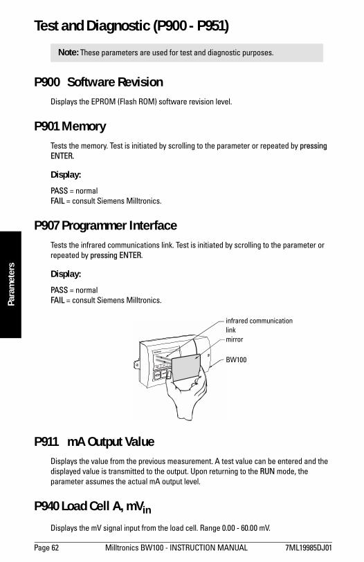
Page 62 Milltronics BW100 - INSTRUCTION MANUAL 7ML19985DJ01
mm
mm
m
Para
met
ers
Test and Diagnostic (P900 - P951)
P900 Software Revision Displays the EPROM (Flash ROM) software revision level.
P901 Memory Tests the memory. Test is initiated by scrolling to the parameter or repeated by pressing ENTER.
Display:
PASS = normalFAIL = consult Siemens Milltronics.
P907 Programmer Interface Tests the infrared communications link. Test is initiated by scrolling to the parameter or repeated by pressing ENTER.
Display:
PASS = normalFAIL = consult Siemens Milltronics.
P911 mA Output Value Displays the value from the previous measurement. A test value can be entered and the displayed value is transmitted to the output. Upon returning to the RUN mode, the parameter assumes the actual mA output level.
P940 Load Cell A, mVin
Displays the mV signal input from the load cell. Range 0.00 - 60.00 mV.
Note: These parameters are used for test and diagnostic purposes.
infrared communication linkmirror
BW100
7ML19985DJ01 Milltronics BW100 - INSTRUCTION MANUAL Page 63
mm
mm
m
Parameters
P941 Load Cell B, mVin
Displays the mV signal input from the load cell. Range 0.00 - 60.00 mV.
P942 V/F converter, Vin
Displays the input voltage to the voltage to frequency converter. Range 0 - 3.98 V
P943 V/F converter, fout
Displays the output frequency of the voltage to frequency converter. Range 0 - 131,072
P944 Power sensor Displays a voltage supply reference for diagnostic purposes.
P949 Diagnostic Errors Enables or disables diagnostic error checking, E101 - E104
Entry:
0 = disable 1 = enable
Refer to Troubleshooting on page 65.
P950 Zero register Registers the number of zero calibrations that have been done since the last master reset.
P951 Span Register Registers the number of span calibrations that have been done since the last master reset.
P952 Design Load Displays the value of the design load, which corresponds to the full scale value for alarm and mA output functions. The design load is calculated, based on the design rate and design speed.
End of test and diagnostic parameters.
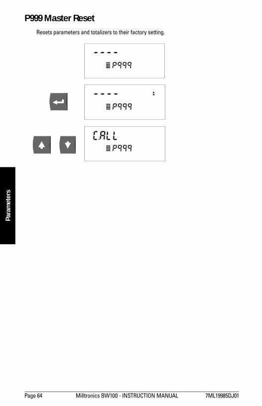
Page 64 Milltronics BW100 - INSTRUCTION MANUAL 7ML19985DJ01
mm
mm
m
Para
met
ers
P999 Master Reset Resets parameters and totalizers to their factory setting.
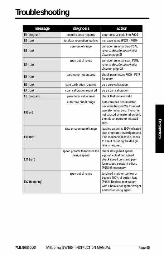
7ML19985DJ01 Milltronics BW100 - INSTRUCTION MANUAL Page 65
mm
mm
m
Parameters
Troubleshooting
message diagnosis action E1 (program) security code required enter access code into P000
E2 (run) totalizer resolution too low increase value (P631 - P639)
E3 (run) zero out of range consider an initial zero P377,
refer to Recalibration/Initial Zero on page 33
E4 (run) span out of range consider an initial span P388,
refer to Recalibration/Initial Span on page 36
E5 (run) parameter not entered check parameters P005 - P017
for entry
E6 (run) zero calibration required do a zero calibration
E7 (run) span calibration required do a span calibration
E8 (program) parameter value error check that value is valid
E9(run)
auto zero out of range auto zero has accumulated deviation beyond 2% from last operator initial zero. If error is not caused by material on belt, then do an operator initiated zero.
E10 (run)
rate or span out of range loading on belt is 300% of rated load or greater. Investigate and if no mechanical cause, check to see if re-rating the design rate is required.
E11 (run)
speed greater than twice the design speed
check design belt speed against actual belt speed, check speed constant, per-form speed constant adjust (P018) if necessary
E12 (factoring)
span out of range test load is either too low or beyond 100% of design load (P952). Replace test weight with a heavier or lighter weight and try factoring again.
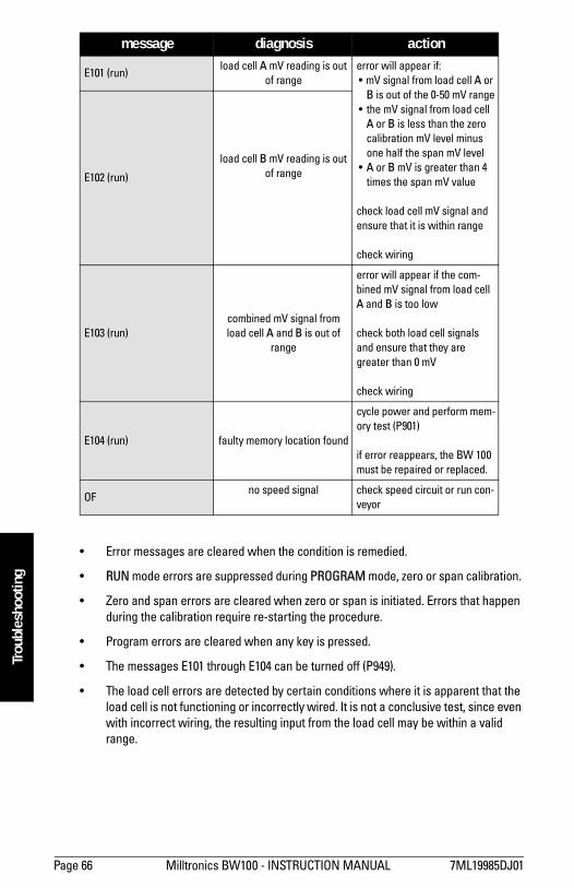
Page 66 Milltronics BW100 - INSTRUCTION MANUAL 7ML19985DJ01
mm
mm
m
Trou
bles
hoot
ing
Error messages are cleared when the condition is remedied.
RUN mode errors are suppressed during PROGRAM mode, zero or span calibration.
Zero and span errors are cleared when zero or span is initiated. Errors that happen during the calibration require re-starting the procedure.
Program errors are cleared when any key is pressed.
The messages E101 through E104 can be turned off (P949).
The load cell errors are detected by certain conditions where it is apparent that the load cell is not functioning or incorrectly wired. It is not a conclusive test, since even with incorrect wiring, the resulting input from the load cell may be within a valid range.
E101 (run) load cell A mV reading is out
of rangeerror will appear if: mV signal from load cell A or
B is out of the 0-50 mV range the mV signal from load cell
A or B is less than the zero calibration mV level minus one half the span mV level
A or B mV is greater than 4 times the span mV value
check load cell mV signal and ensure that it is within range
check wiring
E102 (run)
load cell B mV reading is out of range
E103 (run) combined mV signal from load cell A and B is out of
range
error will appear if the com-bined mV signal from load cell A and B is too low
check both load cell signals and ensure that they are greater than 0 mV
check wiring
E104 (run) faulty memory location found
cycle power and perform mem-ory test (P901)
if error reappears, the BW 100 must be repaired or replaced.
OF no speed signal check speed circuit or run con-
veyor
message diagnosis action
7ML19985DJ01 Milltronics BW100 - INSTRUCTION MANUAL Page 67
mm
mm
m
Troubleshooting
MaintenanceThe BW100 requires no maintenance.
The external surface of the enclosure may be cleaned using a vacuum cleaner and a clean dry paint brush. The display window should be cleaned with a moist non-abrasive cloth.
It is a good idea to check the associated load sensing device, according to its instruction manual.
Software UpdatesThe software can be updated from a floppy disk by use of a PC (IBM Compatible) with Milltronics Dolphin software. It is recommended that a reset (P999) is done after the software update followed by zero and span calibrations.
Direct zero entry (P367) and direct span entry (P368) will suffice in lieu of dynamic zero and span calibrations. Therefore, zero and span counts should be recorded prior to doing the software update.
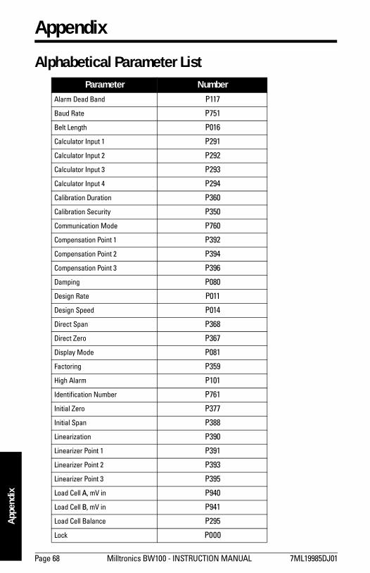
Page 68 Milltronics BW100 - INSTRUCTION MANUAL 7ML19985DJ01
mm
mm
m
App
endi
x
Appendix
Alphabetical Parameter ListParameter Number
Alarm Dead Band P117
Baud Rate P751
Belt Length P016
Calculator Input 1 P291
Calculator Input 2 P292
Calculator Input 3 P293
Calculator Input 4 P294
Calibration Duration P360
Calibration Security P350
Communication Mode P760
Compensation Point 1 P392
Compensation Point 2 P394
Compensation Point 3 P396
Damping P080
Design Rate P011
Design Speed P014
Direct Span P368
Direct Zero P367
Display Mode P081
Factoring P359
High Alarm P101
Identification Number P761
Initial Zero P377
Initial Span P388
Linearization P390
Linearizer Point 1 P391
Linearizer Point 2 P393
Linearizer Point 3 P395
Load Cell A, mV in P940
Load Cell B, mV in P941
Load Cell Balance P295
Lock P000
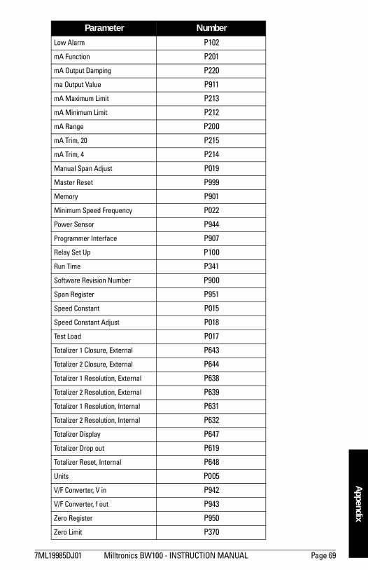
7ML19985DJ01 Milltronics BW100 - INSTRUCTION MANUAL Page 69
mm
mm
m
Appendix
Low Alarm P102
mA Function P201
mA Output Damping P220
ma Output Value P911
mA Maximum Limit P213
mA Minimum Limit P212
mA Range P200
mA Trim, 20 P215
mA Trim, 4 P214
Manual Span Adjust P019
Master Reset P999
Memory P901
Minimum Speed Frequency P022
Power Sensor P944
Programmer Interface P907
Relay Set Up P100
Run Time P341
Software Revision Number P900
Span Register P951
Speed Constant P015
Speed Constant Adjust P018
Test Load P017
Totalizer 1 Closure, External P643
Totalizer 2 Closure, External P644
Totalizer 1 Resolution, External P638
Totalizer 2 Resolution, External P639
Totalizer 1 Resolution, Internal P631
Totalizer 2 Resolution, Internal P632
Totalizer Display P647
Totalizer Drop out P619
Totalizer Reset, Internal P648
Units P005
V/F Converter, V in P942
V/F Converter, f out P943
Zero Register P950
Zero Limit P370
Parameter Number

Page 70 Milltronics BW100 - INSTRUCTION MANUAL 7ML19985DJ01
mm
mm
m
App
endi
x
Program RecordProgram Record
Parameter Value
P005 Units
P011 Design Rate
P014 Design Speed
P015 Speed Constant
P016 Belt Length
P017 Test Load
P018 Speed Constant Adjust
P019 Manual Span Adjust
P022 Minimum speed Frequency
P080 Damping
PO81 Display Mode
P100 Relay Set Up
P101 High Alarm
P102 Low Alarm
P117 Alarm Dead Band
P200 mA Range
P201 mA Function
P212 mA Min Limit
P213 mA Max Limit
P220 mA Output Damping
P341 Run Time
P350 Calibration Security
P360Calibration Duration
P367 Direct Zero
P368 Direct Span
P370 Zero Limit
P390 Linearization
P391 Linearizer, Point 1
P392 Compensation, Point 1
P393 Linearizer, Point 2
P394 Compensation, Point 2
P395 Linearizer, Point 3
P396 Compensation, Point 3

7ML19985DJ01 Milltronics BW100 INSTRUCTION MANUAL Page 71
P396 Compensation, Point 3
P619 Totalizer Dropout
P631 Total 1 Resolution, Int
P632 Total 2 Resolution, Int
P638 Total 1 Resolution, Ext
P639 Total 2 Resolution, Ext
P643 Total 1 Closure, Ext
P644 Total 2 Closure, Ext
P647 Totalizer Display
P648 Totalizer Reset, Int
P751 Baud Rate
P760 Communication Mode
P761 Identification Number
P900 Software Rev.#
P949 Diagnostic Errors
P950 Zero Register
P951 Span Register
P952 Design Load
Program Record
Parameter Value
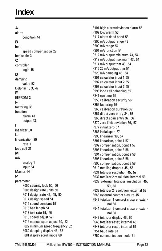
7ML19985DJ01 Milltronics BW100 INSTRUCTION MANUAL Page 72
Index
Aalarm
condition 44Bbelt
speed compensation 29belt scale 3Ccontroller
logic 45Ddamping
value 52Dolphin 1, 3, 47EEEPROM 3Ffactoring 38function
alarm 43output 43
Iinearizer 58Llinearization 39
rate 1load cell 21MmA
analog 1input 54
Master 64Pparameter
P000 security lock 50, 56P005 design rate units 50P011 design rate 43, 45, 50P014 design speed 51P015 speed constant 51P016 belt length 51P017 test rate 51, 56P018 speed adjust 52P019 manual span adjust 30, 52P022 minimum speed frequency 52P080 damping display 43, 52P081 display scroll mode 60
P101 high alarm/deviation alarm 53P102 low alarm 53P117 alarm dead band 53P200 mA output range 43P200 mA range 54P201 mA function 54P212 mA output minimum 43, 54P213 mA output maximum 43, 54P214 mA output trim 43, 54P215 20 mA output trim 54P220 mA damping 43, 54P291 calculator input 1 55P292 calculator input 2 55P293 calculator input 3 55P295 load cell balancing 55P341 run time 55P350 calibration security 56P359 factoring 56P360 calibration duration 56P367 direct zero entry 34, 56P368 direct span entry 37, 56P370 zero limit deviation 56, 57P377 initial zero 57P388 initial span 57P390 linearizer 39, 57P391 linearizer, point 1 57P392 compensation, point 1 57P393 linearizer, point 2 58P394 compensation, point 2 58P395 linearizer, point 3 58P396 compensation, point 3 58P619 totalling dropout 45, 58P631 totalizer resolution 45, 59P632 totalizer 2 resolution, internal 59P638 external totalizer resolution 45,
59, 60P639 totalizer 2 resolution, external 59P643 external contact closure 45P643 totalizer 1 contact closure, exter-
nal 60P644 totalizer 2 contact closure, exter-
nal 60P647 totalizer display 46, 60P648 totalizer reset, internal 45P648 totalzier reset, internal 61P751 baud rate 61P760 communication mode 61
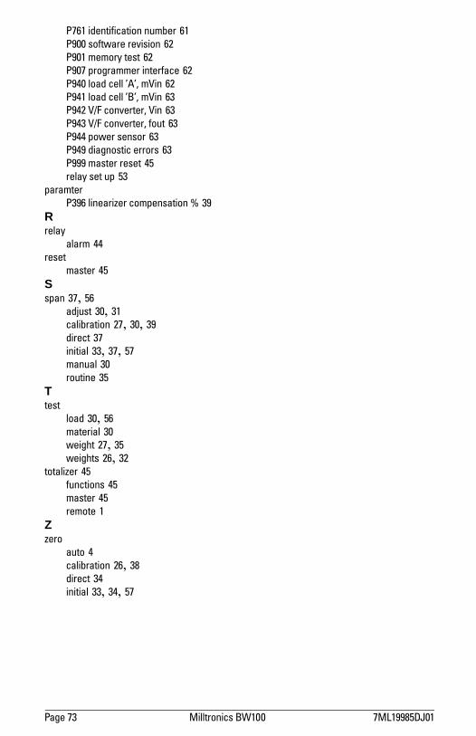
Page 73 Milltronics BW100 7ML19985DJ01
P761 identification number 61P900 software revision 62P901 memory test 62P907 programmer interface 62P940 load cell A, mVin 62P941 load cell B, mVin 63P942 V/F converter, Vin 63P943 V/F converter, fout 63P944 power sensor 63P949 diagnostic errors 63P999 master reset 45relay set up 53
paramterP396 linearizer compensation % 39
Rrelay
alarm 44reset
master 45Sspan 37, 56
adjust 30, 31calibration 27, 30, 39direct 37initial 33, 37, 57manual 30routine 35
Ttest
load 30, 56material 30weight 27, 35weights 26, 32
totalizer 45functions 45master 45remote 1
Zzero
auto 4calibration 26, 38direct 34initial 33, 34, 57

*7ml19985dj01*Rev. 1.1
www.siemens-milltronics.com
Siemens Milltronics Process Instruments Inc.
1954Technology Drive, P.O. Box 4225
Peterborough, ON, Canada K9J 7B1
Tel: (705) 745-2431 Fax: (705) 741-0466
Email: [email protected]
Siemens Milltronics Process Instruments Inc. 2004
Subject to change without prior notice
Printed in Canada


![Untitled-2 [prts-mppolice.nic.in]](https://img.pdfslide.us/doc/110x75/6262905b4f85612f3a09b85a/untitled-2-prts-.jpg)