Embed Size (px)
Citation preview

MILLIPAK SBPM CONTROLLER MANUALFOR SYSTEM VERSION UK0157

Document History______________________________________________________________________________
Document History
Author ReviewerInitials Date Initials Date Version Reason for Modification
PG 31 Oct 05 - - UK0157 Original.
MillipaK SBPM Controller Manual Page 2 21/02/07

Contents______________________________________________________________________________
CONTENTS
Introduction...................................................................................................................................... 5
Safety................................................................................................................................................6
Installation........................................................................................................................................ 7MOUNTING...................................................................................................................................................................... 7MILLIPAK BPM POWER WIRING...................................................................................................................................... 8MILLIPAK LIGHT WIRING EXAMPLE..................................................................................................................................10
Calibrator........................................................................................................................................12DRIVE HOURS COUNTER................................................................................................................................................. 13CALIBRATOR SECURITY LEVELS........................................................................................................................................14NAVIGATION.................................................................................................................................................................. 15ADJUSTMENTS................................................................................................................................................................ 16STATUS AND TEST INFORMATION...................................................................................................................................... 17
Configuration..................................................................................................................................18SYSTEM CONFIGURATION................................................................................................................................................. 18
System Voltage...................................................................................................................................................... 19System I/O Configuration......................................................................................................................................20Contactor chopping...............................................................................................................................................24Accelerator Full /Zero Setting.............................................................................................................................. 25Motor Poles...........................................................................................................................................................26Maximum Motor RPM.......................................................................................................................................... 27Phase Adjustment..................................................................................................................................................28
PERFORMANCE................................................................................................................................................................29Control Mode........................................................................................................................................................ 29Speed Control PI Gains........................................................................................................................................ 30Acceleration Delay................................................................................................................................................32Deceleration Delay............................................................................................................................................... 32Direction Change Deceleration Delay................................................................................................................. 32Neutral Deceleration Delay.................................................................................................................................. 32Regen Braking.......................................................................................................................................................33Braking Levels.......................................................................................................................................................33Footbraking ..........................................................................................................................................................34Creep Speed.......................................................................................................................................................... 36Maximum Speed.................................................................................................................................................... 37Accelerator Characteristics.................................................................................................................................. 38
Features...........................................................................................................................................39STANDARD CONTROLLER FEATURES.................................................................................................................................. 39
Power Steer........................................................................................................................................................... 40Seat Switch............................................................................................................................................................ 41Handbrake Switch................................................................................................................................................. 42Cutback speeds......................................................................................................................................................43Reverse Speed....................................................................................................................................................... 44Pump Contactor.................................................................................................................................................... 45External LED Drive.............................................................................................................................................. 46Traction Motor Over-Temperature Input............................................................................................................. 47Drive Hours Meter................................................................................................................................................ 48Personality Checksum...........................................................................................................................................49Line Contactor Drop out.......................................................................................................................................50
MillipaK SBPM Controller Manual Page 3 21/02/07

Contents______________________________________________________________________________
Alarm Buzzer.........................................................................................................................................................51Electric Outboard Drive and Low Battery Warning.............................................................................................52Temporary Current Boost..................................................................................................................................... 53
SAFETY FEATURES.......................................................................................................................................................... 54Start Up Sequence.................................................................................................................................................54FS1 Recycle...........................................................................................................................................................55SRO (Static return to off)...................................................................................................................................... 56Belly Switch...........................................................................................................................................................57Anti-Rollback........................................................................................................................................................ 58Anti-Rolloff............................................................................................................................................................59Idle Fault...............................................................................................................................................................60Motor Stall Protection.......................................................................................................................................... 61Fail-safe................................................................................................................................................................ 62
Controller Protection Features........................................................................................................63TEMPERATURE MONITORING.............................................................................................................................................63
Maximum Temperature Logging...........................................................................................................................63SAFE OPERATING AREA (SOA).......................................................................................................................................65UNDER-VOLTAGE AND OVER-VOLTAGE PROTECTION..............................................................................................................66
Commissioning Checklist...............................................................................................................69PERSONALITY RECORD.................................................................................................................................................... 70
Fault Finding.................................................................................................................................. 72FAULT CLEARANCE.........................................................................................................................................................73FAULT REPORTING FORM.................................................................................................................................................74SOFTWARE VERSION AND SERIAL NUMBER INDICATION........................................................................................................75
Specifications................................................................................................................................. 76POWER CONFIGURATIONS.................................................................................................................................................76EMC STANDARDS.......................................................................................................................................................... 76SOCKET B PROTECTION....................................................................................................................................................76CONTACTOR DRIVE RATINGS............................................................................................................................................. 76ANALOGUE INPUT IMPEDANCE.......................................................................................................................................... 76DIGITAL INPUT IMPEDANCE.............................................................................................................................................. 76
EMC Guidelines............................................................................................................................. 77
MillipaK SBPM Controller Manual Page 4 21/02/07

Introduction______________________________________________________________________________
Introduction
The MillipaK SBPM (Sinusoidal Brushless Permanent Magnet) range of controllers provides a new range of power frames for 24V-36V, 250A and 48V, 200A in small highly efficient packages. This is achieved using a Sevcon patented power switching scheme and radical new construction techniques, which enable large powers to be incorporated into very small packages.
The MillipaK provides a completely sealed (IP66) unit containing both power and logic circuitry, as well as all suppression components.
MillipaK supports Sevcon’s existing MOS90 calibrator for adjustment of vehicle performance characteristics.
Controllers are FLASH microprocessor based enabling field re-programming for new features and have numerous user set-up options. The MillipaK uses high frequency (silent) MOSFET power switching technology, to control a 3-phase power frame bridge. Armature current is monitored. Motor feedback is necessary in the form of position sensors. Controllers have been designed to satisfy the requirements of the relevant UL and EC standards.
MillipaK SBPM Controller Manual Page 5 21/02/07

Safety______________________________________________________________________________
Safety
The MillipaK controller contains a triple fail-safe system to give a high level of safety. If the diagnostic LED is not illuminated or flashes, the safety circuit may have tripped and the motor may not drive.
The controller must be used with a line contactor as indicated in the wiring diagrams.As blow-out magnets are fitted to contactors (except 24V) ensure that no magnetic particles can accumulate in the contact gaps and cause malfunction. Ensure that contactors are wired with the correct polarity to their power terminals as indicated by the + sign on the top moulding.
The MillipaK controller may be used with suitable onboard chargers, as supplied by Sevcon.
There are several software features which are intended to prevent inadvertent or unexpected motor movement – Accelerator power up fault and sequence checking. Some of these features cannot be disabled and the appropriate signals must be supplied to the controller before drive will be allowed.
MillipaK SBPM Controller Manual Page 6 21/02/07

Installation Mounting______________________________________________________________________________
Installation
The small footprint of the MillipaK controller gives maximum flexibility to the user for mounting options. The following section gives details of certain criteria that should be considered when situating the controller on a vehicle.
Mounting
The MillipaK BPM unit provides 4 x M6 clearance holes for mounting. The controller should be mounted onto a metal base plate, as large as possible to provide heat-sinking. The surface finish should be flat, clean and burr free and thermal compound should be applied to the controller base before fitting.
Figure 1: MillipaK BPM Dimensions
Maximum terminal torque: M8 terminals – 10NMM6 terminals – 7NM
MillipaK SBPM Controller Manual Page 7 21/02/07

Installation Wiring/Power______________________________________________________________________________
MillipaK BPM Power Wiring
M1
M2
M3
B+
B-
Fuse LineContactor
BatterySupply
BPM Motor
MillipaK SBPM Controller Manual Page 8 21/02/07

Installation Wiring/Power______________________________________________________________________________
Figure 2: MillipaK BPM Power Wiring
MillipaK SBPM Controller Manual Page 9 21/02/07

Installation Wiring/Light______________________________________________________________________________
MillipaK Light Wiring example
123456
0V
+ 10.5VClock
Data Con
nect
or A
1234567891011121314151617181920
Con
nect
or B
FuseBattery +ve
Key-switch
Accel.Pot.
Forward (Dig 1)Reverse (Dig 2)
Battery -ve
Analogue Input 1
12V Output
CALIBRATORSevcontrol
SEL
Analog
Calibrator Detect
Line Contactor*Auxiliary Contactor*
Extra Suppression 1**Extra Suppression 2**
Horn Suppression**
Battery +ve
Battery -ve
Extra Suppression 1 or 2or Horn Suppression
External Contactor /Horn
NOTES:*Contactor Coil Suppression fitted internally.**Extra Suppression and Horn Suppression inputs to be used as shown below:
Encoder - RPS1Encoder - RPS2Encoder - RPS3
Encoder - 0V
Dig I/P 3Dig I/P 4Dig I/P 5Dig I/P 6
Analogue Input 2
Figure 3: MillipaK Light Wiring
MillipaK SBPM Controller Manual Page 10 21/02/07

Installation Wiring/Light______________________________________________________________________________
NOTES:The line and auxiliary contactors are wired to B+, on the switched side of the key-switch.
Pin 12 is available for 100mA supply, typically used for (but not limited to) accelerator modules.
Pins 13,14 & 15 are general-purpose suppression connections and may be used to suppress spikes generated by contactors opening / closing. The internal configuration is shown below:
Pin 16 is used to select FLASH memory program update mode and should normally be left unconnected.
MillipaK SBPM Controller Manual Page 11 21/02/07

Calibrator Calibrator/General______________________________________________________________________________
Calibrator
The Calibrator is a hand-held adjustment unit which can be used to configure and test the system. The MillipaK is designed to work with the Calibrator currently in use with SEVCON's MOS90 system. See diagram below. The menu structure is shown in the Calibrator Map located near the end of this manual.
CALIBRATOR
Sevcontrol
+
-
SELECT
i .8.8.8
Figure 4: MillipaK Calibrator
MillipaK SBPM Controller Manual Page 12 21/02/07

Calibrator Calibrator/ Drive Hours Counter______________________________________________________________________________
Drive Hours Counter
When the Calibrator is first plugged into the unit after power up, the Calibrator shows the Drive Hours Counter. Refer to the Drive Hours Counter section for more information on this function.
With no buttons pressed, the number displayed shows the number of minutes (accurate to 0.5 minutes). Pressing the '-' button displays the number of hours under 1000 and pressing the '-' button displays the number of 1000 x hours.
For example, if the hours counter was 12, 345 hours, 13 minutes and 40 seconds, with no buttons pressed, the display would show 13.5. Minutes are only shown to the nearest 0.5 minutes. If the '-' button was pressed, the display would show 345 (number of hours under 1000) and if the '+' button was pressed, the display would show 12 (number of 1000 x hours).
This is the only time that the hours counter can be viewed. Once the Select button has been pressed to enter the normal calibrator menu structure, it is not possible to return to this point. To view the hours counter again, you must recycle the Keyswitch.
This is also the point at which you can enter a password to enable different levels of access to personalities. Refer to the section below on Calibrator Security Levels for more details.
MillipaK SBPM Controller Manual Page 13 21/02/07
Calibrator Calibrator/Security Levels______________________________________________________________________________
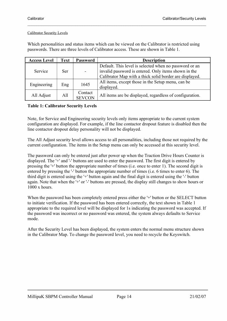
Calibrator Security Levels
Which personalities and status items which can be viewed on the Calibrator is restricted using passwords. There are three levels of Calibrator access. These are shown in Table 1.
Access Level Text Password Description
Service Ser -Default. This level is selected when no password or an invalid password is entered. Only items shown in the Calibrator Map with a thick solid border are displayed.
Engineering Eng 1645 All items, except those in the Setup menu, can be displayed.
All Adjust All Contact SEVCON All items are be displayed, regardless of configuration.
Table 1: Calibrator Security Levels
Note, for Service and Engineering security levels only items appropriate to the current system configuration are displayed. For example, if the line contactor dropout feature is disabled then the line contactor dropout delay personality will not be displayed.
The All Adjust security level allows access to all personalities, including those not required by the current configuration. The items in the Setup menu can only be accessed at this security level.
The password can only be entered just after power up when the Traction Drive Hours Counter is displayed. The '+' and '-' buttons are used to enter the password. The first digit is entered by pressing the '+' button the appropriate number of times (i.e. once to enter 1). The second digit is entered by pressing the '-' button the appropriate number of times (i.e. 6 times to enter 6). The third digit is entered using the '+' button again and the final digit is entered using the '-' button again. Note that when the '+' or '-' buttons are pressed, the display still changes to show hours or 1000 x hours.
When the password has been completely entered press either the '+' button or the SELECT button to initiate verification. If the password has been entered correctly, the text shown in Table 1 appropriate to the required level will be displayed for 1s indicating the password was accepted. If the password was incorrect or no password was entered, the system always defaults to Service mode.
After the Security Level has been displayed, the system enters the normal menu structure shown in the Calibrator Map. To change the password level, you need to recycle the Keyswitch.
MillipaK SBPM Controller Manual Page 14 21/02/07

Calibrator Calibrator/Navigation______________________________________________________________________________
Navigation
The Calibrator uses all three buttons for navigating through the menu structure.
Use the SELECT button to move through the menu structure. When the SELECT button is pressed the next menu item is displayed. The default direction is from left to right, top to bottom.
If the '+' and '-' buttons are held down together, the ID of the currently displayed menu item is shown. For example, if the Armature Current Limit personality was selected, then the ID would be 0.01 (menu 0, item 1). This allows the operator to locate where they are in the map.
If the '+' and '-' buttons are held down together for more than 1 second, the direction through the menu structure is reversed. Now when the SELECT button is pressed the direction is from right to left, bottom to top. In this mode, the LED on the Calibrator will flash. If the '+' and '-' buttons are held down together for more than 1 second again, the direction reverts back to the first direction and the Calibrator LED stops flashing.
The SELECT button is used to navigate through most of the menu structure, however, the Test menu (menu 19) is slightly different. Pressing the SELECT button will take you to the first item in the Test menu, (item 19.01 - Accelerator Demand). To navigate the Test menu, you need to use the '+' and '-' buttons. The '+' button moves up the Test menu and the '-' button moves back down. Pressing the SELECT button at any time exits the Test menu and moves to the first item in the menu structure (menu item 0.01 - Armature Current Limit).
The items which are displayed depends on the current system configuration and the Security Level.
MillipaK SBPM Controller Manual Page 15 21/02/07

Calibrator Calibrator/Adjustments______________________________________________________________________________
Adjustments
Menus 0 to 12 are primarily used for configuring the system. All the personalities that the system uses to configure each function are in one of these menus. A brief description of the purpose of each menu is listed below. For more complete descriptions of each personality refer to the appropriate section in this manual.
Menu Name Purpose0 Current Limits Used to setup maximum currents for motor.1 Braking Levels Used to setup braking strength and performance.
2 Accelerator Used to setup acceleration and deceleration performance and to configure the accelerator input voltage range.
3 Creep Speed Used to setup creep speed.4 Bypass Not Used5 Maximum Speed Used to setup maximum speeds.6 Cutback 1 Speed Used to setup the speed for Cutback Speed 1.7 Cutback 2 Speed Used to setup the speed for Cutback Speed 2.8 Motor Setup Used to setup motor control parameters.9 Power Steer Timer Used to setup the Power Steer timer.10 Seat Delay Used to setup the Seat Switch debounce delay.
11 Additional Personalities
Used to setup additional personalities. These are personalities which do not belong in any of the menus shown above, or they are deemed to be unsuitable for modification by service engineers or end users.
12 System Setup
Used to configure the system at a high level. Items to configure the system I/O and performance are located in here. It is recommended that items in this menu are configured first before any of the other personalities. Unlike the personalities in the other menus, changes to items in this menu do not take affect until the Keyswitch is recycled.
Table 2: Adjustment Menus
MillipaK SBPM Controller Manual Page 16 21/02/07

Calibrator Calibrator/Status and Test Information______________________________________________________________________________
Status and Test Information
Menus 13 to 19 are primarily used for providing information about the system. Every parameter which the system measures in located in one of these menus. A brief description of the purpose of each menu is listed below.
Menu Name Purpose
13 System StatusIf there is a fault active in the system, this menu provides information about what the fault is. Refer to the Diagnostics section for more information.
14 Motor SpeedUsed to show the Motor Speed measurements. Shown as a percentage of the maximum RPM specified, in RPM (20rpm per step) and electrical frequency of the motor.
15 System Voltages
Used to display Battery and Capacitor Voltage measurements. The Battery Voltage measurement shows the voltage measured at the Keyswitch pin (pin 1 on connector B). The Capacitor Voltage measurement shows the voltage measured at the B+ terminal.
16 Motor Voltages Used to show the voltage measured at the Point A terminals.17 Motor Currents Used to show the Armature and Battery Current Measurements.
18 Heatsink Temperature
Used to access the Heatsink Temperature measurement. Refer to the Temperature Monitoring section.
19 Test Menu
Used to access items which allow for testing of all the Analogue and Digital inputs available on connector B. Also displays unit information such as the Software Version, Controller Serial Number and the Personality Checksum. Refer to the appropriate sections for more information on each of these items.
Table 3: Status and Test Information Menus
MillipaK SBPM Controller Manual Page 17 21/02/07

Configuration System______________________________________________________________________________
Configuration
Configuration of the MillipaK controller is split into two categories – system and performance, which will be discussed in turn.
System Configuration
The MillipaK system configuration items relate to how the MillipaK will interface with connected hardware such as the system battery, vehicle control switches, accelerator and the traction motor.
MillipaK SBPM Controller Manual Page 18 21/02/07

Configuration System/Voltage______________________________________________________________________________
System Voltage
The system voltage usually refers to the main system supply battery voltage. The controller uses this information to ensure low and high voltage settings are within an appropriate range.
System VoltageCalibrator Menu Reference:
Power Up12.18
Minimum Maximum Step Size Default24V 48V 2V 48V
MillipaK SBPM Controller Manual Page 19 21/02/07

Configuration System/IO Configuration______________________________________________________________________________
System I/O Configuration
The digital inputs, analogue inputs and contactor drive outputs available on socket B can be configured in a number of ways to suit various applications. Table 4 shows a range of pre-determined settings which are available to the user and should cover the majority of applications, see below:
Digital I/O Value
Description
1 Forward and Reverse switches only with Line Contactor.2 Forward and Reverse switches only with Electric Outboard Drive.3 Walkie vehicle with Speed Cutback 1 switch, Handbrake switch and
Electromagnetic Brake.4 Walkie vehicle with Speed Cutback 1 switch, Brake Override switch
and Electromagnetic Brake.5 Walkie vehicle with Handbrake switch, High Mast switch and
Electromagnetic Brake.6 Walkie vehicle with Speed Cutback 1 switch, Pump Trigger switch
and Pump Contactor.7 Walkie vehicle with Pump Trigger switch, High Mast switch and
Pump Contactor.8 Walkie vehicle with Speed Cutback 1 switch, Speed Cutback 2
switch and Hours Counter Drive.9 Ride On vehicle with Speed Cutback 1 and 2 switches and external
LED drive.10 Ride On vehicle with Speed Cutback 1 switch, Handbrake switch
and external LED drive.11 Ride On vehicle with Traction Motor Overtemperature switch,
Handbrake switch and external LED drive.12 Ride On vehicle with Handbrake switch, Power Steer Trigger switch
and Power Steer Contactor.13 Ride On vehicle with Speed Cutback 1 switch, Power Steer Trigger
switch and Power Steer Contactor.14 Ride On vehicle with Power Steer Trigger switch, Traction Motor
Overtemperature switch and Power Steer Contactor.15 Ride On vehicle with Power Steer Trigger switch, Footbrake switch
and Power Steer Contactor. 16 Ride On vehicle with Handbrake switch, Pump Trigger switch and
Pump Contactor.17 Ride On vehicle with Speed Cutback 1 switch, Pump Trigger switch
and Pump Contactor.18 Ride On vehicle with Speed Cutback 1 and 2 switches and Alarm
Buzzer drive.
Table 4: Description of each Digital I/O configuration.WARNING: Incorrect configuration could cause a vehicle to move unexpectedly,
for example if FS1 was inadvertently configured as a belly switch.
MillipaK SBPM Controller Manual Page 20 21/02/07

Configuration System/IO Configuration______________________________________________________________________________
If your application doesn’t fit any of the above, please contact Sevcon with details of your requirements.
Each of the above configurations allocates the controller i/o as shown below:
Digital Function
Value of Digital I/O Configuration Item1 2 3 4 5 6 7 8 9 10 11 12 13 14 15 16 17 18
Forward B2 B2 B2 B2 B2 B2 B2 B2 B2 B2 B2 B2 B2 B2 B2 B2 B2 B2Reverse B3 B3 B3 B3 B3 B3 B3 B3 B3 B3 B3 B3 B3 B3 B3 B3 B3 B3Belly B4 B4 B4 B4 B4 B4Tiller B5 B5 B5 B5 B5 B5FS1 B4 B4 B4 B4 B4 B4 B4 B4 B4 B4Seat B5 B5 B5 B5 B5 B5 B5 B5 B5 B5Speed Cutback 1 B6 B6 B6 B6 B6 B6 B6 B6 B6Speed Cutback 2 B7 B7 B7Handbrake B7 B7 B7 B7 B7 B7P. Steer Trigger B6 B7 B7 B7Pump Trigger B7 B7 B6 B7High Mast B6 B6Motor Over Temp B6 B6Brake Override B7Footbrake B6Line Contactor B8 B8 B8 B8 B8 B8 B8 B8 B8 B8 B8 B8 B8 B8 B8 B8 B8 B8P. Steer Contactor B9 B9 B9 B9Pump Contactor B9 B9 B9 B9Electro Brake B9 B9 B9External LED B9 B9 B9Hours Counter B9Buzzer B9Electric Outboard B9
Table 5: Digital FunctionsNotes:1. Bx refers to Socket B pin numbers.2. All setups have Forward and Reverse Switches and a Line Contactor.3. All Walkie vehicles have Belly and Tiller Switches.4. All Ride On vehicles have FS1 and Seat Switches.
AnalogueFunction
Value of Analogue Input Configuration Item1 2 3 4
Accelerator B10 B11 B10Footbrake B11
Table 6: Analogue FunctionsNotes:1. Bx refers to Socket B pin numbers.2. Configuration 1 does not have an analogue input configured.
Table 6 details which analogue functions are configured for each value of the Analogue Input Configuration Item.
MillipaK SBPM Controller Manual Page 21 21/02/07

Configuration System/IO Configuration______________________________________________________________________________Digital ConfigurationCalibrator Menu Reference:
Power Up12.16
Minimum Maximum Step Size Default1 18 1 As Required
Analogue ConfigurationCalibrator Menu Reference:
Power Up12.17
Minimum Maximum Step Size Default1 4 1 As Required
MillipaK SBPM Controller Manual Page 22 21/02/07

Configuration System/Armature Current Limit______________________________________________________________________________
Armature Current Limit
The armature current limit personality is provided to allow the user to limit the maximum current supplied to the motor to a value lower than the peak rating of the controller.
Armature Current LimitCalibrator Menu Reference:
Immediate0.01
Minimum Maximum Step Size Typical Value50A ABR 10A ABR
ABR – Armature Block Rating refers to the controller maximum peak current.
The above personality allows the armature current limit to be set. The actual armature current limit control is performed using a control loop. The following two personalities can be used to setup this control loop.
Current Limit Prop GainCalibrator Menu Reference:
Immediate0.02
Minimum Maximum Step Size Typical Value0 255 1 As set
Current Limit Int GainCalibrator Menu Reference:
Immediate0.03
Minimum Maximum Step Size Typical Value0 255 1 As set
WARNING: Seek advice from SEVCON before changing these two personality values. Changing these can affect the capability of the current limit function which could damage the unit due to over-current. The factory set values should be suitable for most applications
MillipaK SBPM Controller Manual Page 23 21/02/07

Configuration System/Contactor Chopping______________________________________________________________________________
Contactor chopping
This feature allows 24 V contactors to be used at all battery voltages 24V – 48V, by continuously monitoring the battery voltage and chopping the contactor output pins accordingly, to present an average voltage suitable for 24V coils. Chopping is selectable by the calibrator. Care must be taken to ensure that chopping is always selected if 24V contactors are being used on battery voltages higher than 24V. In applications > 24 volts contactors must be fitted with blow out magnets. Chopping can reduce the overall dissipation in the coils and allows only one set of contactors to be stocked for all battery voltages.
Chopping Frequency approx. = 800Hz (Slightly audible).
Typical contactor coil voltage during chopping = 16 volts.Typical contactor coil voltage during energisation = 24 volts for 1 second.
There are 3 contactor chopping options available via the setup menu: Off, On and 24V. The off setting is used for nominal battery voltage coils, and the On setting is for 24V coils on higher voltage vehicles. Setting to 24V provides chopping for 24V coils and lamps without the drop to 16V after 1s.
When the electric outboard solenoid is configured, both the line contactor and electric outboard solenoid coil voltage will be battery voltage for 100ms during energisation and then reduced to 16 volts.
Chop SelectCalibrator Menu Reference:
Power Up12.01
Options DefaultOFF ON 24V OFF
MillipaK SBPM Controller Manual Page 24 21/02/07
Configuration System/Accelerator______________________________________________________________________________
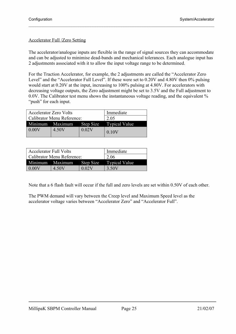
Accelerator Full /Zero Setting
The accelerator/analogue inputs are flexible in the range of signal sources they can accommodate and can be adjusted to minimise dead-bands and mechanical tolerances. Each analogue input has 2 adjustments associated with it to allow the input voltage range to be determined.
For the Traction Accelerator, for example, the 2 adjustments are called the “Accelerator Zero Level” and the “Accelerator Full Level”. If these were set to 0.20V and 4.80V then 0% pulsing would start at 0.20V at the input, increasing to 100% pulsing at 4.80V. For accelerators with decreasing voltage outputs, the Zero adjustment might be set to 3.5V and the Full adjustment to 0.0V. The Calibrator test menu shows the instantaneous voltage reading, and the equivalent % “push” for each input.
Accelerator Zero VoltsCalibrator Menu Reference:
Immediate2.05
Minimum Maximum Step Size Typical Value0.00V 4.50V 0.02V 0.10V
Accelerator Full VoltsCalibrator Menu Reference:
Immediate2.06
Minimum Maximum Step Size Typical Value0.00V 4.50V 0.02V 3.50V
Note that a 6 flash fault will occur if the full and zero levels are set within 0.50V of each other.
The PWM demand will vary between the Creep level and Maximum Speed level as the accelerator voltage varies between “Accelerator Zero” and “Accelerator Full”.
MillipaK SBPM Controller Manual Page 25 21/02/07

Configuration System/Motor Poles______________________________________________________________________________
Motor Poles
The motor poles refer to the number of poles in the motor. The motor poles are used to calculate the mechanical speed of the motor.
Motor PolesCalibrator Menu Reference:
Power Up8.01
Minimum Maximum Step Size Typical Value2 20 2 8
MillipaK SBPM Controller Manual Page 26 21/02/07

Configuration System/Maximum Motor RPM______________________________________________________________________________
Maximum Motor RPM
The maximum motor RPM is the maximum RPM when the motor is unloaded and maximum voltage is applied to the motor. The value is in 100rpm per step size.
Maximum Motor RPMCalibrator Menu Reference:
Power Up8.02
Minimum Maximum Step Size Typical Value10 40 1 20
MillipaK SBPM Controller Manual Page 27 21/02/07

Configuration System/Phase Adjustment______________________________________________________________________________
Phase Adjustment
The phase offset personalities can be adjusted if the sensors are not aligned perfectly in the motor. A value of 128 represents a perfectly aligned motor.
Phase Offset - ForwardCalibrator Menu Reference:
Immediate8.03
Minimum Maximum Step Size Typical Value1 255 1 128
Phase Offset - ReverseCalibrator Menu Reference:
Immediate8.04
Minimum Maximum Step Size Typical Value1 255 1 128
The system corrects the phase angle of the applied voltage to achieve a unity power factor. The feature can disabled if required.NOTE: If this feature is disabled, the phase current could be higher than that measured by the system. Only disable this feature if it is known high phase currents can not occur.
Power Factor Phase CorrectionCalibrator Menu Reference:
Power Up12.15
Options DefaultOFF ON ON
MillipaK SBPM Controller Manual Page 28 21/02/07

Configuration Performance/Control Mode______________________________________________________________________________
Performance
Various parameters may be adjusted to tailor the performance of the vehicle to customer requirements.
Control Mode
The method of motor control may be switched between Torque and Speed control.
Control ModeCalibrator Menu Reference:
Power Up12.03
Options DefaultTorque Speed Torque
Torque ControlIn Torque Control mode, the voltage applied across the motor armature is proportional to the accelerator demand. When climbing an incline, the operator will need to increase the accelerator demand to maintain the speed. When descending an incline, there will be no maximum speed limit applied.
Closed Loop Speed ControlIn Closed Loop Speed Control mode, the speed of the vehicle is controlled to the speed demand from the operator. The controller will increase or decrease power to the motor or will initiate braking to maintain the target speed.
MillipaK SBPM Controller Manual Page 29 21/02/07

Configuration Performance/Speed Control PI Gains______________________________________________________________________________
Speed Control PI Gains
The system uses a PI algorithm for Speed Control. As with all PI algorithms, there are proportional and integral gains which need to be setup correctly. The following diagram illustrates the affect of proportional and integral gains on a standard PI control loop.
As can be seen, too much proportional gain can cause large over-shoot and poor control to occur from the PI Control Loop and too much integral gain can cause the speed to over-shoot and take a long time to get back to the required output.
To set up the speed control proportional and integral gains use the following guidelines.1. Set the speed target to approximately 50%.2. Set the speed control proportional and integral terms to 0. Increase the proportional term
slightly. The motor will drive very slowly but the control will be smooth. Increase the speed control proportional until the motor control is no longer smooth. Once this happens reduce the speed control proportional value to the point at which the control became unstable. Set the speed control proportional to half this value. The motor control will now be smooth, but it will not reach the required speed. This is where the speed control integral gain comes into use.
3. Increase the speed control integral gain to a point where the motor can easily reach the required speed in a time equal to the Acceleration Delay. Ensure that the integral term is not set too high, otherwise the motor speed will over-shoot.
4. Reduce the speed target to approximately 5%.5. Check that the motor control is still smooth. If the control is unstable, decrease the
proportional gain until the control is stable.
MillipaK SBPM Controller Manual Page 30 21/02/07
PI Control Algorithm
0%
20%
40%
60%
80%
100%
120%
140%
160%
180%
0 2 4 6 8 10 12
Tim e
Out
put
Proportional and Integral OK Proportional too high Integral too high Target
Configuration Performance/Speed Control PI Gains______________________________________________________________________________
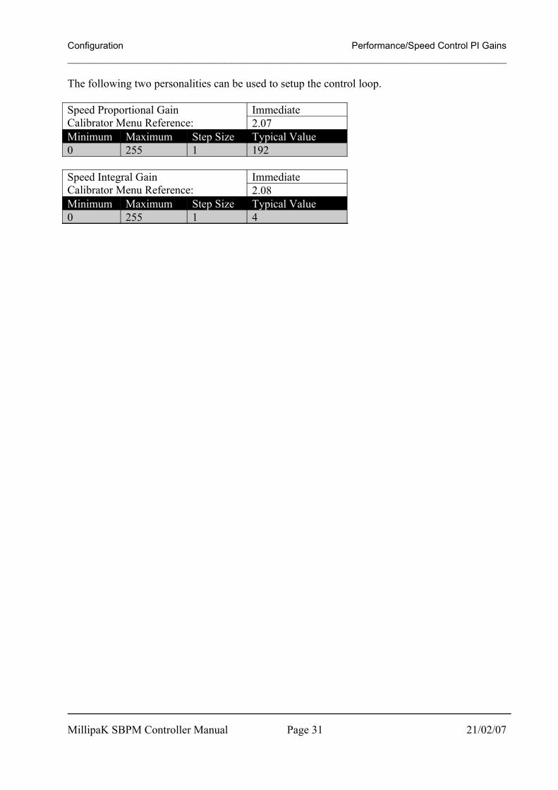
The following two personalities can be used to setup the control loop.
Speed Proportional GainCalibrator Menu Reference:
Immediate2.07
Minimum Maximum Step Size Typical Value0 255 1 192
Speed Integral GainCalibrator Menu Reference:
Immediate2.08
Minimum Maximum Step Size Typical Value0 255 1 4
MillipaK SBPM Controller Manual Page 31 21/02/07
Configuration Performance/Acceleration______________________________________________________________________________
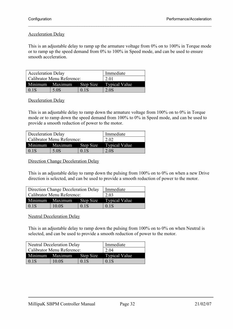
Acceleration Delay
This is an adjustable delay to ramp up the armature voltage from 0% on to 100% in Torque mode or to ramp up the speed demand from 0% to 100% in Speed mode, and can be used to ensure smooth acceleration.
Acceleration DelayCalibrator Menu Reference:
Immediate2.01
Minimum Maximum Step Size Typical Value0.1S 5.0S 0.1S 2.0S
Deceleration Delay
This is an adjustable delay to ramp down the armature voltage from 100% on to 0% in Torque mode or to ramp down the speed demand from 100% to 0% in Speed mode, and can be used to provide a smooth reduction of power to the motor.
Deceleration DelayCalibrator Menu Reference:
Immediate2.02
Minimum Maximum Step Size Typical Value0.1S 5.0S 0.1S 2.0S
Direction Change Deceleration Delay
This is an adjustable delay to ramp down the pulsing from 100% on to 0% on when a new Drive direction is selected, and can be used to provide a smooth reduction of power to the motor.
Direction Change Deceleration DelayCalibrator Menu Reference:
Immediate2.03
Minimum Maximum Step Size Typical Value0.1S 10.0S 0.1S 0.1S
Neutral Deceleration Delay
This is an adjustable delay to ramp down the pulsing from 100% on to 0% on when Neutral is selected, and can be used to provide a smooth reduction of power to the motor.
Neutral Deceleration DelayCalibrator Menu Reference:
Immediate2.04
Minimum Maximum Step Size Typical Value0.1S 10.0S 0.1S 0.1S
MillipaK SBPM Controller Manual Page 32 21/02/07

Configuration Performance/Regen Braking______________________________________________________________________________
Regen Braking
All braking types are implemented using regenerative braking in the 4QPM MillipaK.
Braking can be initiated in one of 4 ways:
(i) Direction Braking. Initiated when the direction switch inputs are reversed during drive. i.e., Reverse is selected when driving in Forward or Forward is selected when driving in Reverse.
(ii) Footbrake Braking. Initiated when the operator depresses the Footbrake pedal and a footbrake input is configured. See section below for more information about setting up and configuring the system for Footbraking.
(iii) Neutral braking. Initiated when the vehicle is put into neutral during drive and neutral braking level is greater than 0%.
(iv) Reduction braking. Initiated when the operator reduces accelerator demand, but does not select neutral. See the section for more information.
Braking Levels
Each Braking Type has its own personality for setting the required braking level. These are shown below:
Direction braking levelCalibrator Menu Reference:
Immediate1.01
Minimum Maximum Step Size Typical Value5% 100% 1% 75%
Neutral braking levelCalibrator Menu Reference:
Immediate1.02
Minimum Maximum Step Size Typical Value1% 100% 1% 10%
Reduction braking levelCalibrator Menu Reference:
Immediate1.03
Minimum Maximum Step Size Typical Value0% 100% 1% 10%
Footbrake braking levelCalibrator Menu Reference:
Immediate1.04
Minimum Maximum Step Size Typical Value0% 100% 1% 0%
MillipaK SBPM Controller Manual Page 33 21/02/07

Configuration Performance/Regen Braking______________________________________________________________________________The four braking levels for direction, neutral, reduction and footbraking are used to determine the strength of the braking. Setting the level to 0% disables braking (Note: Direction Braking cannot be disabled), 1% sets the braking strength to minimum (weakest braking) and 100% sets the braking strength to maximum (strongest braking).
Footbraking
Footbraking can be initiated in one of two ways: Via an analogue input configured as a Footbrake Pot. Using a potentiometer allows the
operator to vary the amount of braking they want. See below. Via a digital input configured as a Footbrake switch. When the switch is active, the system
will brake at the footbrake level.
Footbrake Pot
If the system is configured to use a Footbrake Pot, then the system will allow the operator to vary the amount of footbraking depending on the position of the footbrake pedal. Similar to the Accelerator input there are 2 personalities which can be used to setup the input voltage range of the Footbrake Pot.
Footbrake Zero VoltsCalibrator Menu Reference:
Immediate11.12
Minimum Maximum Step Size Typical Value0.00V 4.50V 0.02V 0.10V
Footbrake Full VoltsCalibrator Menu Reference:
Immediate11.13
Minimum Maximum Step Size Typical Value0.00V 4.50V 0.02V 3.50V
As the input voltage varies from the Zero level to the Full level, the footbrake demand varies from 0% to 100%. When the footbrake demand is at 0%, there is no footbraking. As the footbrake demand increases from 1% to 100%, the braking level applied by the system increases from 50% of the Footbrake Level personality to 100% of the Footbrake Level personality.
For example, assume the system is configured to have a footbrake pot and the Footbrake Level personality is set to 60%. If the operator has not depressed the footbrake pedal, then the voltage into the controller will be outside of the Footbrake Zero Level personality and the footbrake demand will be 0%. There will be no Footbraking.
If the operator starts to press the footbrake pedal, then the footbrake demand will increase. When the demand increases above 0% the system will start braking and will set the braking effort according to the following formula:
MillipaK SBPM Controller Manual Page 34 21/02/07

Configuration Performance/Regen Braking______________________________________________________________________________
ypersonalit level footbrake100
502
demand footbrake effort braking ×
+
=
So, for this example, at 1% demand the braking effort would be
%30
06100
5021
effort braking
=
×
+
=
and at 75% demand the braking effort would be
%5.52
06100
50275
effort braking
=
×
+
=
Footbrake Priority
Footbrake priority can be set to drive or brake and this determines the controller action in the case of the accelerator and footbrake pedal both being active at the same time.
Footbrake PriorityCalibrator Menu Reference:
Power Up12.13
Options DefaultDrive Brake Drive
MillipaK SBPM Controller Manual Page 35 21/02/07

Configuration Performance/Creep Speed______________________________________________________________________________
Creep Speed
The Creep speed is adjustable and is used to select a minimum pulsing level as soon as drive is requested, to minimise delays and dead-bands. The motor voltage is rapidly ramped to the creep level (equivalent to a 100mS acceleration delay).
Creep SpeedCalibrator Menu Reference:
Immediate3.01
Minimum Maximum Step Size Typical Value0% 25% 1% 0%
MillipaK SBPM Controller Manual Page 36 21/02/07

Configuration Performance/Maximum Speed______________________________________________________________________________
Maximum Speed
Adjustment limits the maximum applied voltage to the armature in Torque mode or the maximum speed as a percentage of the maximum speed (rpm) in Speed mode.
Maximum SpeedCalibrator Menu Reference:
Immediate5.01
Minimum Maximum Step Size Typical Value0% 100% 1% 100%
MillipaK SBPM Controller Manual Page 37 21/02/07

Configuration Performance/Accelerator Characteristics______________________________________________________________________________
Accelerator Characteristics
Accelerator Characteristics
0
10
20
30
40
50
60
70
80
90
100
0 20 40 60 80 100
Accelerator Push
Acc
eler
ator
Dem
and
Linear Curved Dual Slope Craw l
Figure 5: Accelerator Characteristics
Accelerator CharacteristicsCalibrator Menu Reference:
Power Up12.10
Options DefaultLinear Curved 2*Slope Crawl Linear
This function is used to vary how much speed is demanded depending on the accelerator position. Setting either Curved, Dual Slope or Crawl gives a smaller change in speed for large changes in accelerator position and is useful for low speed maneuvering.
The accelerator push refers to how much the operator has the accelerator depressed. This is the value which is displayed on item 19.01 in the Test menu on the Calibrator. The Accelerator Demand refers to how much accelerator demand is requested after the Characteristic function is applied. This accelerator demand is then used along with the Creep Speed and Maximum Speed personalities to determine the speed demand for the vehicle.
If a valid direction is selected and the accelerator demand is at 0%, the speed demand will be set to the Creep Speed personality. As the accelerator demand is increased to 100%, the speed demand increases linearly to the Maximum Speed personality.
MillipaK SBPM Controller Manual Page 38 21/02/07

Features Features______________________________________________________________________________
Features
The MillipaK controller has several features designed to offer the user maximum flexibility, safety and performance whilst ensuring the controller is protected against adverse or harsh driving conditions. These features can be split into three categories – standard controller features, safety features and controller protection features.
Standard Controller Features
The following section details the standard features found on a MillipaK controller.
MillipaK SBPM Controller Manual Page 39 21/02/07

Features Standard Features/Power Steer______________________________________________________________________________
Power Steer
A contactor drive is available to control a separate Power Steer motor. An adjustable delay allows the motor to operate for a set time, after the power steer trigger or power steer demand has been removed.
The following triggers are available and configurable for power steer:
Power Steer Trigger Configuration Item
TriggersFS1 switch Fwd or Rev switch Seat switch
0 No No No1 Yes No No2 No Yes No3 Yes Yes No4 No No Yes5 Yes No Yes6 No Yes Yes7 Yes Yes Yes
Table 7: Internal Power Steer Triggers
The software also monitors the motor for movement (if the Anti-Roll-Off feature is enabled) and activates the power steer driver accordingly.
Power Steer Personalities:
Power Steer TimerCalibrator Menu Reference:
Immediate9.01
Minimum Maximum Step Size Typical Value0S 60S 1S 2S
Power Steer TriggerCalibrator Menu Reference:
Power On12.12
Minimum Maximum Step Size Default0 7 1 0
See also contactor drive output configuration (System/Digital IO).
MillipaK SBPM Controller Manual Page 40 21/02/07

Features Standard Features/Seat Switch______________________________________________________________________________
Seat Switch
If the seat switch is opened and the seat switch timer has timed out during drive the controller will stop pulsing and a seat fault will be indicated. Before drive can be restarted the seat switch must be closed, and FS1 and the direction switch must be recycled through neutral. Note the start sequence for drive requires that the seat switch is closed and both the direction and FS1 switches are in the neutral position simultaneously before drive can be initiated. The time period is programmed by means of the Calibrator (Seat Switch Delay). As a setup menu option the seat switch can also inhibit pump operation if required.
Seat DelayCalibrator Menu Reference:
Immediate10.01
Minimum Maximum Step Size Typical Value0.1S 5.0S 0.1S 5.0S
Seat Cuts PumpCalibrator Menu Reference:
Power On12.04
Options Typical ValueOFF ON OFF
MillipaK SBPM Controller Manual Page 41 21/02/07

Features Standard Features/Handbrake Switch______________________________________________________________________________
Handbrake Switch
An input is provided for the connection of a handbrake switch, which if operated will disable armature pulsing.
MillipaK SBPM Controller Manual Page 42 21/02/07

Features Standard Features/Cutback Speeds______________________________________________________________________________
Cutback speeds
There are 2 cutback switch inputs as standard. Each one has an associated personality to adjust the maximum % on when the switch is active. When both switches are active together, the lower speed is selected. The cutback speed inputs are usually normally closed so that a wire off type fault or bad connection initiates a lower speed.
Cutback Speed 1Calibrator Menu Reference:
Immediate6.01
Minimum Maximum Step Size Typical Value0% 100% 1% 100%
Cutback Speed 2Calibrator Menu Reference:
Immediate7.01
Minimum Maximum Step Size Typical Value0% 100% 1% 100%
MillipaK SBPM Controller Manual Page 43 21/02/07

Features Standard Features/Reverse Speed______________________________________________________________________________
Reverse Speed
In some instances the maximum reverse speed of the vehicle is required to be slower than the forward speed. This can be achieved by enabling the reverse speed limit and setting the Maximum Reverse Speed personality accordingly.
Maximum Reverse SpeedCalibrator Menu Reference:
Immediate5.02
Minimum Maximum Step Size Typical Value0% 100% 1% 100%
Reverse Speed Limit EnableCalibrator Menu Reference:
Power Up12.06
Options DefaultOFF ON OFF
MillipaK SBPM Controller Manual Page 44 21/02/07

Features Standard Features/Pump Contactor______________________________________________________________________________
Pump Contactor
A contactor drive is available to control a separate Pump motor. To use this feature, both the Pump Trigger switch and Pump Contactor drive must be configured.
The Pump Contactor drive will activate when the Pump Trigger switch is active and will deactivate 0.5s after the Pump Trigger switch is deactivated. The 0.5s delay is used to de-bounce the Pump Trigger switch.
MillipaK SBPM Controller Manual Page 45 21/02/07

Features Standard Features/External LED Drive______________________________________________________________________________
External LED Drive
To use this feature, the External LED Drive output must be configured.
This output is pulsed at the same rate as the Controller LED. It can be used to control a fault lamp on the vehicle dash board. Any flash faults shown on the LED can also be shown via this output.
If Contactor Chopping is set to On or 24V, the output will only pulse at 24V to prevent the lamp brightness from varying when other contactor outputs are activated.
MillipaK SBPM Controller Manual Page 46 21/02/07

Features Standard Features/Traction Motor Over-Temperature Input______________________________________________________________________________
Traction Motor Over-Temperature Input.
To use this feature, the Traction Motor Over-Temperature Input must be configured. This feature can be used to reduce the power output from the controller if the Traction Motor is over heating.
If the Traction Motor Over-Temperature Input is active, the armature current limit is reduced to 1/3rd of the Armature Current Limit personality.
MillipaK SBPM Controller Manual Page 47 21/02/07

Features Standard Features/Drive Hours Meter______________________________________________________________________________
Drive Hours Meter
The MillipaK maintains a log of the number of hours during which the controller is providing Drive functionality. The Drive Hours Meter runs whenever the vehicle is driving or braking. The current number of logged Drive hours can be viewed using the Calibrator. Refer to the Calibrator section for more information.
MillipaK SBPM Controller Manual Page 48 21/02/07

Features Standard Features/Personality Checksum______________________________________________________________________________
Personality Checksum
As you can see from this Manual and the Calibrator Map, the MillipaK employs quite a few personalities to give the user as much flexibility as possible in setting up their system. After the personalities have been setup to give the desired functionality and performance, most customers will request the same setup for each subsequent controller they purchase.
If you wanted to check that a controller had the correct personalities, it is very tedious and time consuming to check each individual personality in turn. To remove the need for this, the system calculates a checksum value based on the value of each of the personalities in its memory. The checksum value is simply a number between 0 and 255 which is calculated by passing all the personality values through an algorithm.
The Personality Checksum will be same on every unit (with the same number of personalities) for the same set of personality values. This can be used to instantly confirm that all the personalities are correct. The Personality Checksum is located in the Test menu.
MillipaK SBPM Controller Manual Page 49 21/02/07

Features Optional Features/Line Contactor Drop out______________________________________________________________________________
Line Contactor Drop outThe controller will close the line contactor once a successful power up sequence has been carried out, after which drive operation can be achieved. The line contactor will remain closed unless it is opened following a serious fault or power being disconnected.
A further configurable option is available where the line contactor is opened (dropped out) if no drive activity has occurred for a period exceeding the line contactor dropout delay personality. If drive operation is selected once the line has been opened then it will be closed again so that drive operation can occur. Line contactor dropout operation can be selected in the PERS set up:
Line Contactor Drop outCalibrator Menu Reference:
Power Up12.09
Options DefaultOFF ON OFF
Line Contactor Drop out DelayCalibrator Menu Reference:
Immediate11.01
Minimum Maximum Step Size Typical Value0s 60s 1s 5s
MillipaK SBPM Controller Manual Page 50 21/02/07

Features Optional Features/Alarm Buzzer______________________________________________________________________________
Alarm Buzzer
The Buzzer function is used to drive a warning buzzer when the vehicle is moving or in a fault condition. When a Buzzer output is configured, the following options can be selected in the Setup Menu: Off Reverse / Roll Off Motion
If Off is selected, the buzzer output will remain off.
If Reverse / Roll Off is selected, the buzzer output will do one of the following: If the reverse switch is closed or the vehicle is moving in reverse, the buzzer output will
activate continuously. If the controller is applying Anti-Roll Off braking, the buzzer output will be pulsed with an on
time of 0.5s and an off time of 1.0s. If the controller is in a fault condition which would prevent drive, the buzzer output will be
pulsed with an on time of 1.0s and an off time of 1.0s.
If Motion is selected, the buzzer output will do all of the actions described for Reverse / Roll Off, and, in addition, the buzzer output will also activate continuously when the forward switch is closed or the vehicle is moving in forward. Basically, the Buzzer Output is active whenever the vehicle is moving.
Alarm BuzzerCalibrator Menu Reference:
Power Up12.14
Options DefaultOff Rol All Rol
MillipaK SBPM Controller Manual Page 51 21/02/07

Features Optional Features/Electric Outboard Drive______________________________________________________________________________
Electric Outboard Drive and Low Battery Warning
The Electric Outboard Drive is used to drive a solenoid, which, in turn, activates a hook that holds the propeller in place when the REVERSE direction is selected. It is also used to drive an alarm buzzer when the FORWARD direction is selected in conjunction with the Low Battery Warning feature.
When the REVERSE direction is selected the solenoid engages the hook which holds the propeller in place by outputting battery voltage for 100ms, after which the output is chopped at 16V.
When the FORWARD direction is selected, the buzzer alarm will sound if the following is true:- The average battery voltage drops below the Battery Warning Level personality setting
continuously for a period of time longer than that specified by the Battery Warning Timer personality setting.
If the above is true, the buzzer will sound intermittently, and will be ON for 5s and OFF for 20s.
Low Battery Warning LevelCalibrator Menu Reference:
Immediate11.10
Minimum Maximum Step Size Typical Value0.0V 70.0V 0.5V 16.0V
Low Battery Warning TimerCalibrator Menu Reference:
Immediate11.11
Minimum Maximum Step Size Typical Value0.0s 20.0s 0.1s 0.0s
MillipaK SBPM Controller Manual Page 52 21/02/07

Features Optional Features/Temporary Current Boost______________________________________________________________________________
Temporary Current Boost
This is a feature intended to allow the user to temporarily boost the armature current limit in an attempt to improve acceleration.
Immediately after drive demand is requested, the system will set the armature current limit to the Temporary Armature Current Limit personality (not to exceed the controller’s block rating) for the time period specified by the Temporary Armature Current Limit personality setting. After the expiration of the Temporary Armature Current Limit Timer, the system will reset the armature current limit according to the Armature Current Limit personality.
Temporary Armature I LimitCalibrator Menu Reference:
Immediate0.04
Minimum Maximum Step Size Typical Value5A ABR 10A 100A
Temporary Armature I Limit TimerCalibrator Menu Reference:
Immediate0.05
Minimum Maximum Step Size Typical Value0S 10S 1S 4S
MillipaK SBPM Controller Manual Page 53 21/02/07

Safety Features Safety Features/Start Up Sequence______________________________________________________________________________
Safety Features
The features listed in this section are designed with the safety of the operator in mind.
Start Up Sequence
At keyswitch on, the Direction switches must be in the neutral condition simultaneously at least once before drive can be selected. This is a safety feature to help prevent unexpected movement immediately after power up.
Alternatively, the system may be programmed not to check the Direction switches at power on. This option is programmable:
Direction Switch CheckingCalibrator Menu Reference:
Power Up12.08
Options DefaultOFF ON OFF
MillipaK SBPM Controller Manual Page 54 21/02/07

Safety Features Safety Features/FS1 Recycle______________________________________________________________________________
FS1 Recycle
On some vehicles, such as Golf Cars, it is desirable to force the operator to remove accelerator demand before allowing the vehicle to drive in the opposite direction from that it has been traveling in. This feature is implemented as an option.
FS1 RecycleCalibrator Menu Reference:
Power Up12.07
Options DefaultOFF ON OFF
MillipaK SBPM Controller Manual Page 55 21/02/07

Safety Features Safety Features/SRO______________________________________________________________________________
SRO (Static return to off)
This feature is optional in the setup menu and, when specified, forces the following sequences of switch inputs to be followed before drive is allowed: Keyswitch-Direction-FS1 or Keyswitch-FS1-Direction (within the SRO delay). Any other sequence will not allow drive. Drive will be inhibited if FS1 is active for more than the SRO delay with no direction selected. In this case the FS1 will need to be recycled.
Static Return to OffCalibrator Menu Reference:
Power Up12.02
Options DefaultOFF ON OFF
SRO DelayCalibrator Menu Reference:
Immediate11.04
Minimum Maximum Step Size Typical Value0s 5s 1s 2s
MillipaK SBPM Controller Manual Page 56 21/02/07

Safety Features Safety Features/Belly Switch______________________________________________________________________________
Belly Switch
A Belly Switch function is available when the controller is used on a walkie type truck. The feature can be enabled in the setup menu. See this section and wiring diagrams for additional information. Basic operation is as follows:-
Truck moving in Reverse and activating the Belly Switch, accelerator in reverse position:-
a) The controller applies 100% braking.b) The vehicle will accelerate in the Forward direction (Forks Forward) at full speed along the
accelerator curve when the vehicle has stopped.c) All drive will cease after driving for the time given by the Belly Delay personality (See
below).d) The controller will wait for neutral to be selected before drive will operate. If the Belly Switch
is pressed again however, action starts at b) above.
The Belly operation may be set to NORMAL or CONTINUOUS. When set to NORMAL the vehicle will activate belly operation for the duration set by the personality Belly Delay (Calibrator Menu Item 11.03). When set to continuous the belly action will operate for as long as the Belly switch input is active.
Belly DelayCalibrator Menu Reference:
Immediate11.02
Minimum Maximum Step Size Typical Value0.1S 5.0S 0.1S 1.0S
Belly StyleCalibrator Menu Reference:
Power Up12.11
Options DefaultNormal Continuous Normal
MillipaK SBPM Controller Manual Page 57 21/02/07

Safety Features Safety Features/Anti-Rollback______________________________________________________________________________
Anti-Rollback
This is a standard SEVCON feature and is used to help prevent roll back conditions on ramps. If the driver reselects the previous direction after a neutral condition, braking is not attempted, and full drive power is available to restart on a hill.
MillipaK SBPM Controller Manual Page 58 21/02/07

Safety Features Safety Features/Anti-Rolloff______________________________________________________________________________
Anti-Rolloff
This feature is designed so that if a vehicle is powered up, without its handbrake applied, any non-drive condition on a gradient results in the vehicle braking slowly, in a controlled way, down a ramp without running away. The vehicle has to be stationary at least once after power up before the feature is applied.
The Roll-Off Electro-brake option may be set so that the Electro-brake (if fitted & configured) is applied (brakes on) when Roll-Off is detected.
The Roll-Off strength is not adjustable but can be enabled and disabled using the Roll-Off Enable option.
Roll-Off EnableCalibrator Menu Reference:
Immediate11.01
Options DefaultOFF ON ON
Roll-Off E-BrakeCalibrator Menu Reference:
Power On12.05
Options DefaultOFF ON OFF
MillipaK SBPM Controller Manual Page 59 21/02/07

Safety Features Safety Features/Idle Fault______________________________________________________________________________
Idle Fault
This feature is intended to prevent accidents caused by unintentional movement.
The system will exhibit a severe fault (cannot be cleared without a key recycle) and a 2 flash fault will be displayed by the Diagnostic LED mounted on the controller, if the following is true:
- system is powered up- forward or reverse is closed- accelerator push is zero- The above conditions are both true continuously for the time specified by the Idle
Timer personality.
Setting the Idle Timer personality at zero disables the feature.
Idle TimerCalibrator Menu Reference:
Immediate11.05
Minimum Maximum Step Size Typical Value0s 255s 1s 240s
MillipaK SBPM Controller Manual Page 60 21/02/07

Safety Features Safety Features/Motor Stall Protection______________________________________________________________________________
Motor Stall Protection
By monitoring the motor current and voltage over a period of time, the controller is able to detect if a motor stall condition has occurred.
If the armature current rises above the level specified by the Stall Motor Current personality, while the motor voltage drops below the level specified by the Stall Motor Voltage personality, for a continuous period of time longer than that specified by the Stall Timer personality setting, then a motor stall condition will be identified. As a result, the controller will exhibit a severe fault (cannot be cleared without a key recycle), accompanied by a 9 flash fault being displayed by the Diagnostic LED mounted on it.
Setting the Stall Timer personality to zero disables the feature.
Stall TimerCalibrator Menu Reference:
Immediate8.05
Minimum Maximum Step Size Typical Value0s 60s 1s 2s
Stall Motor VoltageCalibrator Menu Reference:
Immediate8.06
Minimum Maximum Step Size Typical Value1V 24V 1V 8V
Stall Motor CurrentCalibrator Menu Reference:
Immediate8.07
Minimum Maximum Step Size Typical Value10A ABR 10A 50A
MillipaK SBPM Controller Manual Page 61 21/02/07

Safety Features Fail-safe______________________________________________________________________________
Fail-safe
The controller’s safety system includes a microprocessor watchdog which can detect software failure, and a hardware fail-safe system which can prevent dangerous runaway conditions in the event of certain hardware failures.Every time the controller is powered-up, the software checks that the fail-safe circuit is able to switch off the MOSFETs and open the contactors.
MillipaK SBPM Controller Manual Page 62 21/02/07

Controller Protection Temperature Monitoring______________________________________________________________________________
Controller Protection Features
There are several in built features which are designed to protect the MillipaK controller from damage due to excessive load currents, voltages and prolonged periods of high demand.
Temperature Monitoring
If the temperature of the power frame exceeds 75oC its maximum available current will be reduced. Note, however, that if the set current limit is less than the maximum available current limit actual cutback will occur at progressively higher temperatures than 75oC. The thermal cutback ensures that the maximum heatsink temperature is limited to 90oC (See Figure 6). When actual cutback occurs the diagnostic LED will flash 8 times. Inspection of the calibrator fault messages will indicate which unit is in thermal cutback.
Thermal Cutback Characteristic
Armature Current Limit
0102030405060708090
100
70 72 74 76 78 80 82 84 86 88 90
Temperature (DegC)
Cur
rent
Lim
it (%
)
Armature Current Limit
Figure 6: Armature Thermal Cutback Characteristic
Maximum Temperature Logging
The system maintains a log of the maximum heatsink temperature measured by the controller. The Maximum Temperature logged is displayed on the Calibrator next to Heatsink Temperature measurement.
To reset the log select the Maximum Temperature Log reset item on the Calibrator. It will display ‘Log’. Press the ‘+’ button and the display will show ‘Clr’ for 2s before returning back to ‘Log’. The maximum temperature has now been reset to the current heatsink temperature.
MillipaK SBPM Controller Manual Page 63 21/02/07

Controller Protection Temperature Monitoring______________________________________________________________________________
Dynamic Power Monitoring
During periods of high current usage the power components of the controller produce considerable heat. The controller monitors the power supplied over time and can reduce the power output if the maximum controller rating is exceeded.
MillipaK SBPM Controller Manual Page 64 21/02/07

Controller Protection Safe Operating Area______________________________________________________________________________
Safe Operating Area (SOA)
The controller’s current may be limited at low motor speeds. This is to reduce the thermal stress on the power components in order to increase long term reliability.
The “Safe Operating Area” is a characteristic of the Mosfets and Freewheel Diodes which make up the power-frame.
For most applications SOA will have little or no effect on the operation of the controller. Its effect is more significant in protecting the controller against adverse loads such as damaged motors and static test rigs.
MillipaK SBPM Controller Manual Page 65 21/02/07

Controller Protection Under/Over Voltage Protection______________________________________________________________________________
Under-voltage and over-voltage protection
In order to prevent a sudden loss in power, the controller will begin to linearly ramp down the current limit, once the average battery voltage falls below a pre-set under-voltage start level. The current will be ramped down to a minimum of 20A and a 7 flash fault indicated if the averaged battery voltage falls below the under-voltage cut-out level.
To protect the controller from over-voltage caused by prolonged regen when ramping down to zero speed, the regen current limit will be reduced when the average battery voltage reaches the over-voltage start level. The current will be ramped down to a minimum of 20A and a 7 flash fault indicated if the averaged battery voltage exceeds the over-voltage cut-out level.
The following calibrator menu items are used to set these values.
Low Voltage StartCalibrator Menu Reference:
Immediate11.06
Minimum Maximum Step Size Typical ValueLow V Cutout
System Voltage
0.5V 18.0V
Low Voltage CutoutCalibrator Menu Reference:
Immediate11.07
Minimum Maximum Step Size Typical Value14.5V Low V Start 0.5V 14.5V
High Voltage StartCalibrator Menu Reference:
Immediate11.08
Minimum Maximum Step Size Typical ValueSystem Voltage
High V Cutout
0.5V High V Cutout
High Voltage CutoutCalibrator Menu Reference:
Immediate11.09
Minimum Maximum Step Size Typical ValueHigh V Start
50.0V or 58.0V
0.5V 50.0V or 58.0V
MillipaK SBPM Controller Manual Page 66 21/02/07

Controller Protection Under/Over Voltage Protection______________________________________________________________________________The maximum High Voltage Cutout depends on the level of the System Voltage item. If the System Voltage is set to 36V or lower, then the maximum is 50.0V. If the System Voltage is set greater than 36V, then the maximum is 58.0V.
MillipaK SBPM Controller Manual Page 67 21/02/07

Calibrator Map
F.WEAK
T IMER
SEAT
X2
X3
X4
X5
BAT
MOTOR (V)
MOTOR (A)
TEMP
T EST
MotorSetup
Power SteerT imer
Seat SwitchDelay
AdditionalPersonalit ies
SystemSetup
Fault Log
SpeedEstimate
SystemVoltages
MotorVoltages
MotorCurrents
HeatsinkTemperature
Test Menu
TOP
NavigationT he operator moves through the Calibrator Map by pressing the SELECT key. The solid line shows the path thethrough the menu structure when the SELECT key is pressed.
In Service Mode (no Password entered) only the items shown with a thick solid border are displayed. When thenext item is hidden (Engineering or All adjust access only), the calibrator moves on the next displayable it em.Items which are not configured will also be hidden, ie the bypass items will not be displayed if the bypasscontactor is not configured.
In Engineering Mode (Password entered) the items shown with a solid border are displayed. When the next itemis hidden (All adjust access only), the calibrator moves on the next displayable item. Items which are notconfigured will also be hidden.
In All Adjust Mode (Password entered) all the items (solid and dashed borders) are displayed.
DirectionBy default , the Calibrator moves from left to right through the menu structure. If the operator presses and holdsthe '+' and '-' keys for more than 1 second the navigat ion direction changes and the Calibrator will move fromright to left through the menu structure. The direction can be restored by holding the '+' and '-' keys for 1 secondagain.
T he direction is indicated by the LED on the Bar Graph. If the LED is lit steadily, the direction is from left toright , else if the LED is flashing the direct ion is from right to left .
Information ItemsT he Test menu only shows information items that cannot be modified. T he operator can move upand down the menu using the '+' and '-' keys. As before, items with a dashed border are only displayed in AllAdjust Mode. If the Operator presses the SELECT key the Calibrator moves to the next menu.
Item IdentificationT he operator can identify the current item by holding down the '+' and '-' keys. For example, holding down the'+' and '-' keys on the High V Cutout personality will display 11.09 (Menu 11 (I.MAX is menu 0), Item 9). Theoperator will use the User Manual to identify the personality from the ID.
CalibratorReference
I.MAX
PLUG
ACCEL.
CREEP
BYPASS
SPEED
SPEED1
SPEED2
Description
CurrentLimits
BrakingLevels
Accelerator
CreepSpeed
Bypass
MaximumSpeed
CutbackSpeed 1
CutbackSpeed 2
T OP
0
1
2
3
4
5
6
7
8
9
10
11
12
13
14
15
16
17
18
19
1 2 3 4 5 6 7 8
9
High V CutoutHigh V Start
Arm I Lim it
Accel Delay Drive Decel Speed Prop Speed Int
Max. Speed
Max RPM
Low V CutoutLine DropoutTim er Low V Start
Chop Select SRO Enable Control Mode Rev SpeedSeat Cuts Pump
Cap. VoltageBattery Voltage
Point A Voltage
Arm. Current
Tem perature
10
11
Map for BPM Controller System Version UK0157.02 - 31st October 2005
12
Status
13 14
FS1 Recy cle
15 16
No of Poles
17
Accel Push Accel Voltage S/W Version Ser No. Date Ser No. ID1 Ser No. ID2Digital 1 Switch Digital 2 Switch Pers Checksum
I Prop Gain I Int Gain
MaxTem perature
Clear MaxTemperature
Speed %
Accel Zero Accel Full
Tem p I Limit Tem p I LimitTimer
Phase OffsetFwd
Phase OffsetRev Stall Timer Stall Voltage Stall Current
Bat WarningLevel
Bat WarningTim erIdle Tim er
Roll-Off Brake
Bat. Current
Speed rpm
Creep Speed
Dir Change Neutral Reduction Footbrake
Dir Decel Neut. Decel
Rev. Speed
Cut Spd 1
Cut Spd 2
Aux Push Aux Voltage Digital 3 Switch Digital 4 Switch Digital 5 Switch Digital 6 Switch
P. Steer Tim er
Seat Delay
Roll-off Belly Delay SRO Delay
Sy stem Voltage
Seq Dir SW Line Dropout Accel Char Belly Sty le Power SteerTrigger FBrake Priority Buzzer Alarm Phase Correct. Digital I/O Analog Input
Footbrake Zero Footbrake Full
Elec Freq (Hz)
MillipaK SBPM Controller Manual Page 68 21/02/07

Commissioning Checklist______________________________________________________________________________
Commissioning Checklist
Controller Mounted on suitable flat heatsink with appropriate heatsink compound ?
Power wiring checked, shortest routes taken where possible ?
Light wiring checked, use calibrator to verify controller correct switch operation.
Accelerator set-up and checked 0 – 100% ?
Personalities all set, checked and record filled out ?
MillipaK SBPM Controller Manual Page 69 21/02/07

Commissioning Personalities Record______________________________________________________________________________
Personality Record
Personality New Setting RangeMinimum Maximum
0.01 Armature Current Limit 50A ABR1
0.02 Imax Proportional Gain 0 2550.03 Imax Integral Gain 0 2550.04 Boost Current Limit 50A ABR1
0.05 Boost Timer 0s 10s1.01 Direction Braking Level 5% 100%1.02 Neutral Braking Level 1% 100%1.03 Reduction Braking Level 0% 100%1.04 Footbrake Braking Level 0% 100%2.01 Acceleration Delay 0.1s 5.0s2.02 Drive Deceleration Delay 0.1s 25.0s2.03 on Change Decel Delay 0.1s 25.0s2.04 Neutral Deceleration Delay 0.1s 25.0s2.05 Accelerator Zero V8 0.00V 4.50V2.06 Accelerator Full V8,9 0.00V 4.50V2.07 Speed Proportional Gain 0 2552.08 Speed Integral Gain 0 2553.01 Creep Speed 0% 25%5.01 Maximum Speed 0% 100%5.02 Maximum Reverse Speed 0% 100%6.01 Cutback Speed 1 0% 100%7.01 Cutback Speed 2 0% 100%8.01 Number of Poles 2 208.02 Maximum Motor RPM/100 10 408.03 Phase Offset – Forward 1 2558.04 Phase Offset – Reverse 1 2558.05 Stall Timer 0s 60s8.06 Stall Voltage 1V 48V8.07 Stall Current 10A ABR1
9.01 Power Steer Timer 0s 60s10.01 Seat Delay 0.1s 5.0s11.01 Roll-Off Enable OFF/ON11.02 Belly Delay 0.1s 5.0s11.03 Line Contac. Dropout Delay 0s 60s11.04 SRO Delay 0s 5s11.05 Idle Timer 0s 255s11.06 Low Voltage Start Low V Cutout System Voltage11.07 Low Voltage Cutout 14.5V Low V Start11.08 High Voltage Start System Voltage High V Cutout11.09 High Voltage Cutout High V Start 50.0V or 70.0V2
11.10 Low Battery Warning Level 14.5V 70.0V
MillipaK SBPM Controller Manual Page 70 21/02/07

Commissioning Personalities Record______________________________________________________________________________
11.11 Low Battery Warning Timer 0.0s 20.0s11.12 Foot Brake Zero Volts 0.00V 4.50V11.13 Foot Brake Full Volts 0.00V 4.50V12.01 Chop Select OFF/ON/24V12.02 SRO Enable OFF/ON12.03 Control Mode TORQUE/SPEED12.04 Seat Cuts Pump OFF/ON12.05 Roll-Off Electro brake OFF/ON12.06 Reverse Speed Limit OFF/ON12.07 FS1 recycle on Dir Change OFF/ON12.08 Drive Switch Check OFF/ON12.09 Line Cont Drop out OFF/ON12.10 Accelerator Characteristics LINEAR/CURVED/2*SLOPE/CRAWL12.11 Belly Style NORMAL/CONTINUOUS12.12 Power Steer Trigger FS1/SEAT/DIRECTION12.13 Foot-brake Priority DRIVE/FOOTBRAKE12.14 Buzzer Alarm Off/REVERSE+ROLLOFF/ALL12.15 Power Factor Correction OFF/ON12.16 Digital I/O 1 1812.17 Analogue I/P 1 412.18 System Voltage 24V 48V
Table 8: Personality Record
MillipaK SBPM Controller Manual Page 71 21/02/07

Fault Finding______________________________________________________________________________
Fault Finding
The MillipaK controller includes a number of features designed to help the user track down operational faults, wiring faults or internal controller faults.The Diagnostic LED mounted next to the calibrator connectors on the front of the controller serves as a simple diagnostic tool as explained below:
ON No fault, normal conditionOFF Internal controller fault
1 flash Personality out of range2 flashes Illegal start condition3 flashes MOSFET Short Circuit4 flashes Contactor fault5 flashes Not used6 flashes Accelerator wire off fault7 flashes Low or High battery voltage8 flashes Over temperature or timed cutback9 flashes Rotor Position Sensor Fault10 flashes Current Measurement Autozero Fault
Table 9: Flash Fault Descriptions
In addition to the LED indication a more detailed description of any faults detected may be found by using the calibrator. Menu item number 13.01 gives a code which corresponds to the following detected faults:
ID Fault Description Flash Fault0 System OK On
1 Thermal CutbackMaximum power available to the motor has been reduced due to excessive Heatsink temperature.
8
2 I2t Current Limit Cutback
Maximum power available to the motor has been reduced by the I2t Current Limit Cutback function.
8
3 Accelerator Wire Off Input wire from accelerator has been disconnected. 6
4 Accelerator Power Up Fault Accelerator push > 5% at power up. 6
5 Belly Fault The Belly switch function has occurred. 26 Seat Fault Drive selected and no seat switch closed. 2
7 FS1 Recycle FS1 switch remained closed during a direction change 2
8 SRO Fault FS1 switch selected for greater the SRO delay with Direction switches open. 2
9 Two Direction Fault Two directions selected together. 2
MillipaK SBPM Controller Manual Page 72 21/02/07

Fault Finding______________________________________________________________________________
10 Sequence Fault Direction or FS1 switch closed at power up. 211 System Idle Fault System Idle timer expired 212 Low Battery Fault Battery voltage is too low. 713 High Battery Fault Battery voltage is too high. 714 High Capacitor Fault Capacitor voltage is too high. 715 System Stall Fault System stall condition occurred 9
16 High Battery Fault with Line Contactor Open
Battery voltage is too high before the line contactor is closed 7
17 Configuration Range Fault A personality is out of range. 1
18 Configuration CRC Fault The personality CRC is incorrect 1
19 Line Contactor Welded Fault Line contactor is welded. 4
20 Line Contactor did not Close Fault Line contactor is open circuit. 4
21 RPS Fault Rotor position sensor is in an invalid state 9
22 Autozero Fault The current measurement autozero value is not in the permitted range. 10
23 MOSFETs Short Circuit
The armature MOSFETs have been detected as being short circuit. 3
24 MOSFET Off MOSFETs did not pulse during power on failsafe checks (failsafe circuit enabled). 0
25 MOSFET On MOSFETs pulsed during power on failsafe checks (failsafe circuit disabled). 0
26 Power Up MOSFET Short Circuit
The armature MOSFETs have been detected as being short circuit at system power up. 3
27 Drive 2 Off Contactor 2 did not pulse during power on failsafe checks (failsafe circuit enabled). 0
28 Drive 2 On Contactor 2 pulsed during power on failsafe checks (failsafe circuit disabled). 0
29 Drive 1 Off Contactor 1 did not pulse during power on failsafe checks (failsafe circuit enabled). 0
30 Drive 1 On Contactor 1 pulsed during power on failsafe checks (failsafe circuit disabled). 0
Table 10: Fault Numbers and Descriptions
Fault Clearance
Any fault indication will be cleared by re-initiating the start sequence after the cause of the fault has been removed.
MillipaK SBPM Controller Manual Page 73 21/02/07

Fault Finding______________________________________________________________________________
Fault Reporting Form
Sevcon is committed to improving the quality if all of its products. Please help us by using this form to report faults to Sevcon. Please give as much detail as possible. Use extra sheets if required. Fax this form to +44 191 482 4223.
Your Name Telephone NumberYour Company email addressVehicle Manufacturer
Vehicle Type
Controller Type Part numberSerial Number Software VersionDate / Time that fault first occurred.Exact Fault Message (calibrator or display)When did the fault message appear?
during drive / when the vehicle stopped / in neutral / after a keyswitch off-on(delete as applicable)
How did the fault occur?Please describe:The vehicle speed.The approximate gradient (up or down hill)Pedal and switch changes by the driverWhat happened to the vehicle when the fault occurred
What is the status of the vehicle now?Is there a fault message at key-switch on?Can it be driven?
Table 11: Fault Reporting Form
MillipaK SBPM Controller Manual Page 74 21/02/07

Fault Finding______________________________________________________________________________
Software Version and Serial Number indication
For identification purposes and to assist in queries, the Software version, and the controller serial number are indicated in the calibrator Test Menu.
The Software version is shown in the Test menu. When giving the Software Version, the entire number should be quoted (i.e. MM.mm.nn).
The Serial Number is shown across three items in the Test menu. The first item is the date code and the next two are the identifier. All these items need to be used to get the complete serial number. The format is:
Test Item: Ser No. Date Ser No. ID1 Ser No. ID2Serial Number: MMYY AA BB
Table 12: Serial Number Format
MMYY gives the month and year when the controller was manufactured. (e.g. 0701 indicates July, 2001). AABB are combined to give a 4 digit identifier which is simply a number from 0001 to 9999. When giving the Serial Number, the entire number should be quoted (i.e. MMYYAABB).
The MillipaK range of controllers use the latest FLASH technology to allow In System Reprogramming. This is achieved without having to remove the controller from its installation – all that is needed is connection to the 6-way calibrator socket.
MillipaK SBPM Controller Manual Page 75 21/02/07

Specifications______________________________________________________________________________
Specifications
The following specifications apply to all MillipaK controllers.
Power Configurations
At present the MillipaK SBPM controller is available in the following power configurations:
Housing Voltage ArmatureHP Large 24-36V 250AHP Large 48V 200A
Table 13: Power Configurations
EMC standards
All MillipaK variants are tested to and conform to EN12895.
Socket B protection
All user connections on socket B are protected against indefinite short circuit to battery minus and battery positive.
Contactor drive ratings
All contactor drives are rated at 3A peak (10s) and 1.5A continuous. All the drives have reverse battery connection protection, inbuilt freewheel diode and are internally protected against short circuit at power up only.
Analogue Input Impedance
The two analogue inputs are internally pulled up to +12v via a 12k resistor. This is primarily designed for use with 5k potentiometers, but may also be used with suitable voltage sources.
Digital Input Impedance
The digital inputs are internally pulled up and are active LOW. They therefore must be connected to battery minus to operate a function. Maximum resistance to battery minus to operate is 500ohms.
MillipaK SBPM Controller Manual Page 76 21/02/07

EMC Guidelines_____________________________________________________________________________
EMC Guidelines
The following guidelines are intended to help vehicle manufacturers to meet the requirements of the EC directive 89/336/EEC for Electromagnetic Compatibility.Any high speed switch is capable of generating harmonics at frequencies that are many multiples of its basic operating frequency. It is the objective of a good installation to contain or absorb the resultant emissions.All wiring is capable of acting as a receiving or transmitting antenna. Wiring should be arranged to take maximum advantage of the structural metal work inherent in most vehicles. Vehicle metalwork should be electrically linked with conductive braids.
Power Cables
All cables should be routed within the vehicle framework and kept as low in the structure as is practical - a cable run within a main chassis member is better screened from the environment than one routed through or adjacent to an overhead guard.Power cables should be kept short to minimise emitting and receiving surfacesShielding by the structure may not always be sufficient - cables run through metal shrouds may be required to contain emissions.Parallel runs of cables in common circuits can serve to cancel emissions - the battery positive and negative cables following similar paths is an example.Tie all cables into a fixed layout and do not deviate from the approved layout in production vehicles. A re-routed battery cable could negate any approvals obtained.
Signal Cables
All wiring harnesses should be kept short.Wiring should be routed close to vehicle metalwork.All signal wires should be kept clear of power cables or made from screened cable Control wiring should be kept clear of power cables when it carries analogue information - for example, accelerator wiring. Tie all wiring securely and ensure wiring always follows the same layout.
Controller
Thermal and EMC (emissive) requirements tend to be in opposition. Additional insulation between the controller assembly and the vehicle frame work reduce capacitive coupling and hence emissions but tend to reduce thermal ratings. A working balance needs to be established by experiment.The complete installation should be documented, in detail, and faithfully reproduced on all production vehicles. When making changes, consider their effect on compliance ahead of any consideration of cost reduction or other “improvement”.
MillipaK SBPM Controller Manual Page 77 21/02/07