Embed Size (px)
Citation preview

MFH
High Effi ciency and High Feed Cutter
MFHMFH● Applicable to various applications
with 3 types of inserts● Multi-functional cutter for ramping,
helical milling, etc.● MEGACOAT NANO with long tool life
New grade for diffi cult-to-cut material
Milling

Facing, Shouldering
Slotting Ramping
Helical Milling Vertical Milling (Plunging)
1
MFHHigh chattering resistance and applicable to various applications with 3 types of inserts Increased chip evacuation and shortened cutting time
● Cutting Force (Shock) Comparison when Biting Workpiece
Multi-functional cutter for ramping, helical milling, etc.
Various applications with 3 types of inserts
3D convex cutting edge reduces shock when biting workpiece
GMGM (General purpose)
LDLD (Large ap)
FLFL (Wiper edge)
Shape
Application
1st recommendation for general application→Facing, Pocketing,
Helical milling
MAX ap=5mm→Applicable for scale
removal at high efficiency
→Applicable for both roughing and
finishing, for small machining center
3 types of inserts according to your application Applicable to wide range of applications∙For inclination angle during contouring, see page 10
ngFacing R i
Vc=150m/min, fz=1.5mm/t, ap×ae=1.5×31.5mmS50C, Dry, Cutter dia.
Cutting with the ae (mm) that receivesthe maximum impact
Cutti
ng F
orce
Competitor AMHF Competitor B
Chart shows resultant cutting force
0
2,000
4,000
7,000
5,000
3,000
1,000
Convex Edge
POINT 1
POINT 2 POINT 3
※GM type is applicable for all the above applications※LD type and FL type are not applicable to Helical Milling,
Plunging and Contouring of rising wall (Please refer to the back cover)

2
MFH High Effi ciency and High Feed Cutter
For titanium alloy and precipitation hardened stainless steel. Stabilized milling operation and long tool life with Kyocera's MEGACOAT NANO coating technology.
Newly Developed Tougher
Substrate
Wear Resistance Comparison● SKD11 ● Ni-base heat resistant alloy
New grade for difficult-to-cut material which helps control sudden fracture and deliver machine stability
Applicable to a wide variety of workpiecematerials from steel to heat-resistant alloy
0.000 5 10 15 20
0.10
0.20
0.30
CA6535 (GM)Competitor E Competitor F
< Cutting Conditions >Vc=30m/min, fz=0.8mm/t, ap×ae=1.0×40mm, Wet
Wea
r [m
m]
Cutting Time [min] < Cutting Conditions >Vc=150m/min, fz=1.5mm/t, ap×ae=1.0×16mm, Dry
Wea
r [m
m]
0.000 2010 30 40 50 60 70 80
0.10
0.20
0.30
PR1525(GM)
Competitor C
Competitor D
Cutting Time [min]
CA6535
PR1535
Processed area
SFVAF22B (Forged alloy steel)
・Turbine parts ・Vc=160m/min ・fz=1.17mm/t・ap×ae=1.5×max.160mm ・Dry・MFH160R-14-8T (8 edges) ・SOMT140520ER-GM (PR1525)
PR1525 Chip evacuation=720cc/min
Competitor F Chip evacuation=240cc/min
Efficiency: 3 times
SUS304F
・Clutch ・Vc=120m/min ・fz=1.2mm/t・ap×ae=1.0×20mm ・Dry・MFH32-S32-10-2T (2 edges) ・SOMT100420ER-GM (PR1535)
PR1535 Chip evacuation=58cc/min
Competitor G Chip evacuation=36cc/min
Chattering reducedEfficiency: 1.6 times
Case Studies
MEGACOATLayer structure of MEGACOAT
TiN Smooth & less adhesion
Oxidation and wear resistant
Prevent peeling of coating layer
Frictional wear resistant
For Ni-base heat resistant alloy and martensitic stainless steel. High heat resistance and wear resistance with CVD coating. Improved stability due to thin film coating technology.
∙Low cutting noise even at 3 times higher feed rate∙Good edge condition,with no chipping and stable cutting
∙Competitor G caused chattering but MFH realized stable machining∙Good edge condition and long tool life
(User Evaluation) (User Evaluation)
POINT 4
α -Al2O3
Special Interlayer
TiCN

3
Efficiency can be improved by using large ap machining for scale removal first and thereafter by using high-feed
machining for roughing
MFH improved machining efficiency by 2.6 times compared to conventional cutter
Large ap for scale removal(fz=0.25mm/t ap=4mm)
High feed rate after scaling(fz=1.5mm/t ap=2mm)
MFH
・ Roughing for scale removal (2 passes): Large apVc=200m/min fz=0.25mm/tap×ae=4×40mmVf=1,264mm/min
・ Roughing (2 passes)after scaling:High feed rateVc=200m/min fz=1.5mm/tap×ae=2×40mm Vf=7,583mm/minWorkpiece:SS400
Chip removal =404cc/min
※MFH063R-14-5T-22M(Cutter dia.φ63, 5 teeth)
Conventional 45°cutter
・ Roughing (4 passes): Same ap and feedrateVc=200m/min fz=0.25mm/tap×ae=3×40mm Vf=1,264mm/minWorkpiece:SS400
Chip removal =151cc/min
LD type for both large ap and high feed rate
High resistant to chattering and better surface roughness even with
long overhang machining
FL type for fine surface finish
Recommended for the following applicationsMFH
LD type is available for large ap ※(Max.5mm) as well as high feed rate at low ap machining
※3.5mm for 10-type insert
● Roughing (2 passes)Vc=200m/min fz=0.4mm/tap×ae=1.5×35 Vf=2,038mm/minWorkpiece:S55C
● Finishing: Surface roughness orientedVc=200m/min fz=0.2mm/tap×ae=0.2×35 Vf=1,019mm/minWorkpiece:S55C
※MFH050R-10-4T-M (Cutter dia.φ50, 4 teeth)
Low cutting force design and wide wiper edge delivered both chattering reduction
and fine surface finish
① Machining with long overhang ② Machining which requiressevere surface roughness
③ Suitable for small machining center, too
I want a cutter which can be used both at large ap and high feed rate
Large apmachining
I want a cutter which can finish fine surface even
with low rigidity machine.
※Finishing surface roughness depends on the cutting conditions
High feed machining
High chatteringresistant
Fine surface finish with wide wiper edge
※Cutter dia.φ63,5 teeth
New solution with MFH
Rz=3.2µ m
4
MFH High Effi ciency and High Feed Cutter
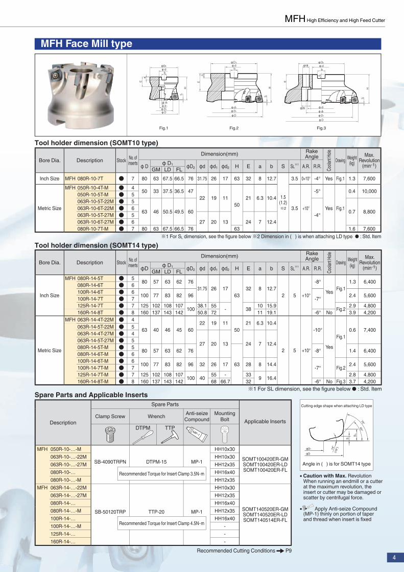
MFH Face Mill type
Spare Parts and Applicable Inserts
Description
Spare Parts
Applicable InsertsClamp Screw Wrench Anti-seize
CompoundMounting
BoltDTPM TTP
MFH 050R-10-…-M
SB-4090TRPN DTPM-15 MP-1
HH10x30
SOMT100420ER-GMSOMT100420ER-LDSOMT100420ER-FL
063R-10-…-22M HH10x30063R-10-…-27M HH12x35080R-10-… HH16x40080R-10-…-M HH12x35
MFH 063R-14-…-22M
SB-50120TRP TTP-20 MP-1
HH10x30
SOMT140520ER-GMSOMT140520ER-LDSOMT140514ER-FL
063R-14-…-27M HH12x35080R-14-… HH16x40080R-14-…-M HH12x35100R-14-… HH16x40100R-14-…-M -125R-14-… -160R-14-… -
SH
bdD2
a
18
26
E
d1
d2
DD1
bdD2
aE
d 1
D1
D
SH
bdD2
aE
HS
d 2
d1
D1
D
Fig.3Fig.2Fig.1
Tool holder dimension (SOMT14 type)
Bore Dia. Description Stock No. of inserts
Dimension(mm) Rake Angle Drawing Weight
(kg)Max.
Revolution(min-1)φD φ D1 φD2 φd φd1 φd2 H E a b S SL※1 A.R. R.R.GM LD FL
Inch Size
MFH 080R-14-5T ● 5 80 57 63 62 7631.75 26 17
6332 8 12.7
2 5 +10°
-8°
Yes Fig.11.3 6,400 080R-14-6T ● 6
100R-14-6T ● 6 100 77 83 82 96 -7° 2.4 5,600 100R-14-7T ● 7125R-14-7T ● 7 125 102 108 107 100 38.1 55 - 38 10 15.9 Fig.2 2.9 4,800 160R-14-8T ● 8 160 137 143 142 50.8 72 11 19.1 -6° No 3.9 4,200
Metric Size
MFH 063R-14-4T-22M ● 4
63 40 46 45 6022 19 11
5021 6.3 10.4
2 5 +10°
-10°
Yes
Fig.10.6 7,400063R-14-5T-22M ● 5
063R-14-4T-27M ● 4
27 20 13 24 7 12.4063R-14-5T-27M ● 5080R-14-5T-M ● 5 80 57 63 62 76
63
-8° 1.4 6,400 080R-14-6T-M ● 6100R-14-6T-M ● 6 100 77 83 82 96 32 26 17 28 8 14.4 -7° Fig.2 2.4 5,600 100R-14-7T-M ● 7125R-14-7T-M ● 7 125 102 108 107 100 40 55 - 33 9 16.4 2.8 4,800 160R-14-8T-M ● 8 160 137 143 142 68 66.7 32 -6° No Fig.3 3.7 4,200
※1 For SL dimension, see the fi gure below ● : Std. Item
Tool holder dimension (SOMT10 type)
Bore Dia. Description Stock No. of inserts
Dimension(mm) Rake Angle Drawing Weight
(kg)Max.
Revolution(min-1)φ D φ D1 φD2 φd φd1 φd2 H E a b S SL※1 A.R. R.R.GM LD FL
Inch Size MFH 080R-10-7T ● 7 80 63 67.5 66.5 76 31.75 26 17 63 32 8 12.7
1.5(1.2)※2
3.5 0+10° -4° Yes Fig.1 1.3 7,600
Metric Size
MFH 050R-10-4T-M ● 4 50 33 37.5 36.5 4722 19 11
5021 6.3 10.4
3.5 +10°
-5°
Yes Fig.1
0.4 10,000 050R-10-5T-M ● 5063R-10-5T-22M ● 5
63 46 50.5 49.5 60 -4° 0.7 8,800 063R-10-6T-22M ● 6063R-10-5T-27M ● 5
27 20 13 24 7 12.4063R-10-6T-27M ● 6080R-10-7T-M ● 7 80 63 67.5 66.5 76 63 1.6 7,600
※1 For SL dimension, see the fi gure below ※2 Dimension in ( ) is when attaching LD type ● : Std. Item
S
SL
14°
(16°
)
45°75°
D1
D
Angle in ( ) is for SOMT14 type
Cutting edge shape when attaching LD type
● Caution with Max. Revolution When running an endmill or a cutter at the maximum revolution, the insert or cutter may be damaged or scatter by centrifugal force.
● Apply Anti-seize Compound (MP-1) thinly on portion of taper and thread when insert is fi xed
Recommended Torque for Insert Clamp 3.5N・m
Recommended Torque for Insert Clamp 4.5N・m
Coola
nt Ho
leCo
olant
Hole
Recommended Cutting Conditions P9

5
MFH End Mill shank type (SOMT10 type)
Spare Parts and Applicable Inserts
Description
Spare Parts
Applicable InsertsClamp Screw Wrench Anti-seize
CompoundDTPM
MFH …-10-…SB-4075TRP DTPM-15 MP-1 SOMT100420ER-GM
SOMT100420ER-LDSOMT100420ER-FL
Fig.1
Fig.2
Fig.3
Fig.4
D
D1
S
L
d h6
d h6
d h6
D
D1
S
L
d h6
● Caution with Max. RevolutionWhen running an endmill or a cutter at the maximum revolution, the insert or cutter may be damaged or scattered by centrifugal force.
● Apply Anti-seize Compound (MP-1) thinly on portion of taper and thread twhen insert is fi xed.
Recommended Torque for Insert Clamp 3.5N・m
Recommended Cutting Conditions P9
Tool holder dimension (SOMT10 type)
Description Stock No. of inserts
Dimension(mm) Rake Angle Drawing Weight
(kg)Max.
Revolution(min-1)φD φ D1 φD2 L ℓ S SL A.R. R.R.GM LD FL
Standard (Straight)
MFH 25-S25-10-2T ● 2 25 8 12.5 11.5 25 140 60
1.5(1.2)※
3.5 +10° -5° Yes
Fig.3 0.4 17,000 28-S25-10-2T ● 2 28 11 15.5 14.5 40 Fig.1 0.5 15,500 32-S32-10-2T ● 2 32 15 19.5 18.5
32 150
70 Fig.30.8
14,000 32-S32-10-3T ● 335-S32-10-2T ● 2 35 18 22.5 21.5
50 Fig.113,000 35-S32-10-3T ● 3
40-S32-10-3T ● 3 40 23 27.5 26.5 0.9 11,500 40-S32-10-4T ● 4
Standard(Weldon)
MFH 25-W25-10-2T ● 2 25 8 12.5 11.5 25 117 601.5
(1.2)※
3.5 +10° -5° YesFig.4 0.4 17,000
32-W32-10-3T ● 3 32 15 19.5 18.532
131 700.7
14,000 40-W32-10-3T ● 3 40 23 27.5 26.5 112 50 Fig.2 11,500 40-W32-10-4T ● 4
Long Shank(Straight)
MFH 25-S25-10-2T-200 ● 2 25 8 12.5 11.5 25200
1201.5
(1.2)※
3.5 +10° -5° Yes
Fig.3 0.6 17,000 28-S25-10-2T-200 ● 2 28 11 15.5 14.5 40 Fig.1 0.7 15,500 32-S32-10-2T-200 ● 2 32 15 19.5 18.5
32120 Fig.3 1.0 14,000
35-S32-10-2T-200 ● 2 35 18 22.5 21.5 50 Fig.1 1.4 13,000 40-S32-10-4T-250 ● 4 40 23 27.5 26.5 250 1.5 11,500
※Dimension in ( ) is when attaching LD type ●:Std. Item
Cool
ant H
ole
S
SL
14°
45°75°
D1
D
Cutting edge shape when attaching LD type

6
MFH High Effi ciency and High Feed Cutter
MFH End Mill shank type (SOMT14 type)
MFH modular type head
Spare Parts and Applicable Inserts
Description
Spare Parts
Applicable InsertsClamp Screw Wrench Anti-seize Compound
DTPM
MFH …-10-…SB-4075TRP DTPM-15 MP-1 SOMT100420ER-GM
SOMT100420ER-LDSOMT100420ER-FLRecommended Torque for Insert Clamp 3.5N・m
● Caution with Max. RevolutionWhen running an endmill or a cutter at the maximum revolution, the insert or cutter may be damaged by centrifugal force.
● Coat Anti-seize Compound (MP-1) thinly on portion of taper and thread when insert is fi xed.
Spare Parts and Applicable Inserts
Description
Spare Parts
Applicable InsertsClamp Screw Wrench Anti-seize Compound
TTP
MFH …-14-…SB-50120TRP TTP-20 MP-1 SOMT140520ER-GM
SOMT140520ER-LDSOMT140514ER-FLRecommended Torque for Insert Clamp 4・5N・m
● Caution with Max. RevolutionWhen running an endmill or a cutter at the maximum revolution, the insert or cutter may be damaged by centrifugal force.
● Coat Anti-seize Compound (MP-1) thinly on portion of taper and thread when insert is fi xed.
Tool holder dimension
※Dimension in ( ) is when attaching LD type ●: Std. Item
Description Stock No. of inserts
Dimension(mm) Rake Angle Max.Revolution
(min-1)φD φD1 φD2 φd L L1 M1 H B S SL A.R. R.R.GM LD FLMFH 25-M12-10-2T ● 2 25 8 12.5 11.5 23 12.5 57 35 M12xP1.75 19 10
1.5(1.2)
※
3.5 +10° -5° Yes
17,00028-M12-10-2T ● 2 28 11 15.5 14.5 15,50032-M16-10-2T ● 2 32 15 19.5 18.5
30 17 63 40 M16xP2.0 24 12
14,00032-M16-10-3T ● 335-M16-10-2T ● 2 35 18 22.5 21.5 13,00035-M16-10-3T ● 340-M16-10-3T ● 3 40 23 27.5 26.5 11,50040-M16-10-4T ● 4
Coo
lant
Hol
e
Tool holder dimension (SOMT14 type)
●: Std. Item
Description Stock No. of inserts
Dimension(mm) Rake AngleDrawing Weight
(kg)Max. Revolution
(min-1)φ D φ D1 φ d L ℓ S SL A.R. R.R.GM LD FLMFH 50-S42-14-3T ● 3 50 27 33 32
42 150 50 2 5 +10° -10° YesFig.1 1.4 8,800
63-S42-14-4T ● 4 63 40 46 45 Fig.2 1.7 7,40080-S42-14-5T ● 5 80 57 63 62 -8° 2.3 6,400
Coo
lant
Hol
e
S
L
L1
D2D
1
d
M1DH
A
A
A-A Section
dh6
S
L
D1
D
dh6
S
L
D
D1
Fig.1
Fig.2
S
SL
16°
45°75°
D1
D
Cutting edge shape when attaching LD type
S
SL
14°
45°75°
D1
D
Cutting edge shape when attaching LD type

7
L1 L2
φD
M
Arbor Description
Applicable End Mill (mm)Actual end mill depth
DescriptionCutting Dia. Dimension
M L2φD L1
BT30K- M12-45 MFH25-M12-10-2T φ2535
42.8 7.8
MFH28-M12-10-2T φ28 45.5 10.5
BT40K- M12-55 MFH25-M12-10-2T φ2535
44.6 9.6
MFH28-M12-10-2T φ28 47.6 12.6
M16-65 MFH32-M16-10-○T φ32
40
51.2 11.2
MFH35-M16-10-○T φ35 60.2 20.2
MFH40-M16-10-○T φ40 64 24
Actual end mill depth
Description Stock
Dimension (mm)
Coolant Hole
Arbor(Two-face clamping)
Applicable End Mill
L φD1 φd1 S ℓ1 ℓ2 M1 G
BT30K- M12-45 ● 45 23 12.5 24 9 15 M12×P1.75 Yes BT30 MFH25-M12··MFH28-M12··
BT40K- M12-55 ● 55 23 12.5 24
9
15 M12×P1.75
Yes BT40
MFH25-M12··MFH28-M12··
M16-65 ● 65 30 17 25 16 M16×P2MFH32-M16··MFH35-M16··MFH40-M16··
Dimensions
Arbor Identifi cation System
Two-face Clamping Spindle
Thread Size for Clamping Length from the Gage
BT30 K - M12 - 45Arbor Size
M1
S
1 2d1D1
L
GCoolant Hole(Center Through System)
Applicable End MillApplicable Arbor
Attachment image
Gage line(Gage Face)
BT Arbor ( for modular type head/two face contact )
●: Std. Stock
8
MFH High Effi ciency and High Feed Cutter
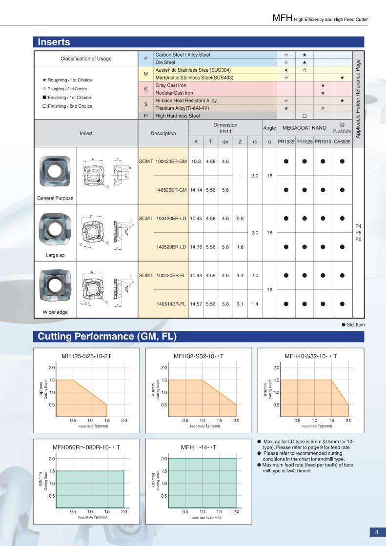
Cutting Performance (GM, FL)
InsertsClassifi cation of Usage P
Carbon Steel / Alloy Steel ★ ★Die Steel ★ ★
★:Roughing / 1st Choice
★:Roughing / 2nd Choice
■:Finishing / 1st Choice
□:Finishing / 2nd Choice
MAustenitic Stainless Steel(SUS304) ★ ★Martensitic Stainless Steel(SUS403) ★ ★
KGray Cast Iron ★Nodular Cast Iron ★
SNi-base Heat Resistant Alloy ★ ★Titanium Alloy(Ti-6Al-4V) ★ ★
H High Hardness Steel □
Insert DescriptionDimension
(mm) Angle MEGACOAT NANO CVDCVD Coated Carbide
A T φd Z rε α PR1535 PR1525 PR1510 CA6535
General Purpose
A
φd
α
T
rε
SOMT 100420ER-GM 10.3 4.58 4.6
- 2.0 16
● ● ● ●
P4P5P6
140520ER-GM 14.14 5.56 5.8 ● ● ● ●
Large ap
A
α
φd
TZ
rε
SOMT 100420ER-LD 10.45 4.58 4.6 0.9
2.0 16
● ● ● ●
140520ER-LD 14.76 5.56 5.8 1.6 ● ● ● ●
Wiper edge
A
α
φd
TZ
rεSOMT 100420ER-FL 10.44 4.58 4.6 1.4 2.0
16
● ● ● ●
140514ER-FL 14.57 5.56 5.8 3.1 1.4 ● ● ● ●
●:Std. Item
0.5
0.5 1.0 1.5 2.0
1.0
2.0
1.5
MFH050R~080R-10-・T
Cut
ting
Dept
h
Feed Rate fz(mm/t)
ap(
mm
)
0.5
0.5 1.0 1.5 2.0
1.0
2.0
1.5
MFH‥-14-・T
Feed Rate fz(mm/t)
ap(
mm
)C
uttin
g De
pth
● Max. ap for LD type is 5mm (3.5mm for 10-type). Please refer to page 9 for feed rate.
● Please refer to recommended cutting conditions in the chart for endmill type.
● Maximum feed rate (feed per tooth) of face mill type is fz=2.0mm/t.
0.5
0.5 1.0 1.5 2.0
1.0
2.0
1.5
MFH25-S25-10-2T
Feed Rate fz(mm/t)
ap(
mm
)C
uttin
g De
pth
0.5
0.5 1.0 1.5 2.0
1.0
2.0
1.5
MFH32-S32-10-・T
Feed Rate fz(mm/t)
ap(m
m)
Cut
ting
Dept
h
0.5
0.5 1.0 1.5 2.0
1.0
2.0
1.5
MFH40-S32-10-・T
ap(m
m)
Cut
ting
Dept
h
Feed Rate fz(mm/t)
Appl
icab
le H
olde
r Ref
eren
ce P
age

9
Recommended Cutting Conditions
Workpiece
Holder Description and Feed Rate (fz:min/t) Recommended Insert Grade(Vc:m/min)
MFH25- MFH32- MFH40- MFH…R-10 MFH…-14MEGACOAT NANO CVD Coated Carbide
PR1535 PR1525 PR1510 CA6535
GM
Carbon Steel (SxxC) 0.5~0.8~1.0 0.5~1.0~1.5 0.5~1.2~1.8 0.5~1.5~2.0 ★
120~180~250★
120~180~250 - -
Alloy Steel (SCM etc.) 0.5~0.8~1.0 0.5~1.0~1.5 0.5~1.2~1.8 0.5~1.5~2.0 ★100~160~220
★100~160~220 - -
Die Steel(SKD/NAK etc.)(~40HRC) 0.5~0.7~0.8 0.5~0.8~1.2 0.5~1.0~1.6 0.5~1.2~1.8 ★
80~140~180★
80~140~180 - -
Die Steel(SKD/NAK etc.)(40~50HRC) 0.2~0.3~0.5 0.2~0.5~0.8 0.2~0.6~0.9 0.2~0.7~1.0 ★
60~100~130★
60~100~130 - -
Austenitic StainlessSteel(SUS304 etc.) 0.5~0.7~0.8 0.5~0.8~1.2 0.5~1.0~1.6 0.5~1.2~1.8 ★
100~160~200★
100~160~200 - -
Martensitic Stainless Steel (SUS403 etc.)
0.5~0.7~0.8 0.5~0.8~1.2 0.5~1.0~1.6 0.5~1.2~1.8 ★150~200~250 - - ★
180~240~300
Precipitation Hardened Stainless Steel (SUS630 etc.)
0.5~0.7~0.8 0.5~0.8~1.2 0.5~1.0~1.6 0.5~1.2~1.8 ★90~120~150 - - -
Gray Cast Iron(FC) 0.5~0.8~1.0 0.5~1.0~1.5 0.5~1.2~1.8 0.5~1.5~2.0 - - ★120~180~250 -
Nodular Cast Iron 0.5~0.7~0.8 0.5~0.8~1.2 0.5~1.0~1.6 0.5~1.2~1.8 - - ★100~150~200 -
Ni-base Heat Resistant Alloy 0.2~0.4~0.6 0.2~0.5~0.9 0.2~0.6~1.0 0.2~0.8~1.2 ★
20~30~50 - - ★20~30~50
Titanium Alloy(Ti-6Al-4V) 0.2~0.4~0.6 0.2~0.5~0.9 0.2~0.6~1.0 0.2~0.8~1.2 ★
40~60~80 - ★30~50~70 -
LD
Carbon Steel (SxxC)
0.5~0.8~1.0(ap≦1.0mm)0.06~0.1~0.2(ap≦3.5mm)
0.5~1.0~1.5(ap≦1.0mm)0.06~0.15~0.3(ap≦3.5mm)
0.5~1.2~1.8(ap≦1.0mm)0.06~0.2~0.3(ap≦3.5mm)
0.5~1.5~2.0(ap≦1.0mm)0.06~0.2~0.3(ap≦3.5mm)
0.5~1.5~2.0(ap≦2.0mm)0.06~0.2~0.4(ap≦5.0mm)
★120~180~250
★120~180~250 - -
Alloy Steel (SCM etc.) 0.5~0.8~1.0(ap≦1.0mm)0.06~0.1~0.2(ap≦3.5mm)
0.5~1.0~1.5(ap≦1.0mm)0.06~0.15~0.3(ap≦3.5mm)
0.5~1.2~1.8(ap≦1.0mm)0.06~0.2~0.3(ap≦3.5mm)
0.5~1.5~2.0(ap≦1.0mm)0.06~0.2~0.3(ap≦3.5mm)
0.5~1.5~2.0(ap≦2.0mm)0.06~0.2~0.4(ap≦5.0mm)
★100~160~220
★100~160~220 - -
Die Steel(SKD/NAK etc.)(~40HRC)
0.5~0.7~0.8(ap≦1.0mm)0.06~0.08~0.15(ap≦3.5mm)
0.5~0.8~1.2(ap≦1.0mm)0.06~0.1~0.2(ap≦3.5mm)
0.5~1.0~1.6(ap≦1.0mm)0.06~0.15~0.2(ap≦3.5mm)
0.5~1.2~1.8(ap≦1.0mm)0.06~0.15~0.2(ap≦3.5mm)
0.5~1.2~1.8(ap≦2.0mm)0.06~0.15~0.3(ap≦5.0mm)
★80~140~180
★80~140~180 - -
Die Steel(SKD/NAK etc.)(40~50HRC)
0.2~0.3~0.5(ap≦1.0mm)0.03~0.05~0.1(ap≦3.5mm)
0.2~0.5~0.8(ap≦1.0mm)0.03~0.08~0.15(ap≦3.5mm)
0.2~0.6~0.9(ap≦1.0mm)0.03~0.1~0.15(ap≦3.5mm)
0.2~0.7~1.0(ap≦1.0mm)0.03~0.1~0.15(ap≦3.5mm)
0.2~0.7~1.0(ap≦2.0mm)0.03~0.1~0.2(ap≦5.0mm)
★60~100~130
★60~100~130 - -
Austenitic Stainless Steel(SUS304 etc.)
0.5~0.7~0.8(ap≦1.0mm)0.06~0.08~0.15(ap≦3.5mm)
0.5~0.8~1.2(ap≦1.0mm)0.06~0.1~0.2(ap≦3.5mm)
0.5~1.0~1.6(ap≦1.0mm)0.06~0.15~0.2(ap≦3.5mm)
0.5~1.2~1.8(ap≦1.0mm)0.06~0.15~0.2(ap≦3.5mm)
0.5~1.2~1.8(ap≦2.0mm)0.06~0.15~0.3(ap≦5.0mm)
★100~160~200
★100~160~200 - -
Martensitic Stainless Steel (SUS403 etc.)
0.5~0.7~0.8(ap≦1.0mm)0.06~0.08~0.15(ap≦3.5mm)
0.5~0.8~1.2(ap≦1.0mm)0.06~0.1~0.2(ap≦3.5mm)
0.5~1.0~1.6(ap≦1.0mm)0.06~0.15~0.2(ap≦3.5mm)
0.5~1.2~1.8(ap≦1.0mm)0.06~0.15~0.2(ap≦3.5mm)
0.5~1.2~1.8(ap≦2.0mm)0.06~0.15~0.3(ap≦5.0mm)
★150~200~250 - - ★
180~240~300
Precipitation Hardened Stainless Steel(SUS630 etc.)
0.5~0.7~0.8(ap≦1.0mm)0.06~0.08~0.15(ap≦3.5mm)
0.5~0.8~1.2(ap≦1.0mm)0.06~0.1~0.2(ap≦3.5mm)
0.5~1.0~1.6(ap≦1.0mm)0.06~0.15~0.2(ap≦3.5mm)
0.5~1.2~1.8(ap≦1.0mm)0.06~0.15~0.2(ap≦3.5mm)
0.5~1.2~1.8(ap≦2.0mm)0.06~0.15~0.3(ap≦5.0mm)
★90~120~150 - - -
Gray Cast Iron (FC) 0.5~0.8~1.0(ap≦1.0mm)0.06~0.1~0.2(ap≦3.5mm)
0.5~1.0~1.5(ap≦1.0mm)0.06~0.15~0.3(ap≦3.5mm)
0.5~1.2~1.8(ap≦1.0mm)0.06~0.2~0.3(ap≦3.5mm)
0.5~1.5~2.0(ap≦1.0mm)0.06~0.2~0.3(ap≦3.5mm)
0.5~1.5~2.0(ap≦2.0mm)0.06~0.2~0.4(ap≦5.0mm) - - ★
120~180~250 -
Nodular Cast Iron 0.5~0.7~0.8(ap≦1.0mm)0.06~0.08~0.15(ap≦3.5mm)
0.5~0.8~1.2(ap≦1.0mm)0.06~0.1~0.2(ap≦3.5mm)
0.5~1.0~1.6(ap≦1.0mm)0.06~0.15~0.2(ap≦3.5mm)
0.5~1.2~1.8(ap≦1.0mm)0.06~0.15~0.2(ap≦3.5mm)
0.5~1.2~1.8(ap≦2.0mm)0.06~0.15~0.3(ap≦5.0mm) - - ★
100~150~200 -
Ni-base Heat Resistant Alloy
0.2~0.4~0.6(ap≦1.0mm)0.03~0.05~0.1(ap≦3.5mm)
0.2~0.5~0.9(ap≦1.0mm)0.03~0.08~0.15(ap≦3.5mm)
0.2~0.6~1.0(ap≦1.0mm)0.03~0.1~0.15(ap≦3.5mm)
0.2~0.8~1.2(ap≦1.0mm)0.03~0.1~0.15(ap≦3.5mm)
0.2~0.8~1.2(ap≦2.0mm)0.03~0.1~0.2(ap≦5.0mm)
★20~30~50 - - ★
20~30~50Titanium Alloy(Ti-6Al-4V)
0.2~0.4~0.6(ap≦1.0mm)0.03~0.05~0.1(ap≦3.5mm)
0.2~0.5~0.9(ap≦1.0mm)0.03~0.08~0.15(ap≦3.5mm)
0.2~0.6~1.0(ap≦1.0mm)0.03~0.1~0.15(ap≦3.5mm)
0.2~0.8~1.2(ap≦1.0mm)0.03~0.1~0.15(ap≦3.5mm)
0.2~0.8~1.2(ap≦2.0mm)0.03~0.1~0.2(ap≦5.0mm)
★40~60~80 - ★
30~50~70 -
Inse
rt
★: 1st recommendation ★: 2nd recommendation

10
MFH High Effi ciency and High Feed Cutter
Recommended Cutting Conditions
Workpiece
Holder Description and Feed Rate(fz:mm/t)
Recommended Insert Grade(Vc:m/min)
MFH25- MFH32- MFH40- MFH…R-10 MFH…-14MEGACOAT NANO CVD
CVD Coated Carbide
PR1535 PR1525 PR1510 CA6535
FL
Carbon Steel (SxxC) 0.5~0.8~1.0 0.5~1.0~1.5 0.5~1.2~1.8 0.5~1.5~2.0 ★
120~180~250★
120~180~250 - -
Alloy Steel (SCM etc.) 0.5~0.8~1.0 0.5~1.0~1.5 0.5~1.2~1.8 0.5~1.5~2.0 ★
100~160~220★
100~160~220 - -
Die Steel(SKD/NAK etc.)(~40HRC) 0.5~0.7~0.8 0.5~0.8~1.2 0.5~1.0~1.6 0.5~1.2~1.8 ★
80~140~180★
80~140~180 - -
Die Steel(SKD/NAK etc.)(40~50HRC) 0.2~0.3~0.5 0.2~0.5~0.8 0.2~0.6~0.9 0.2~0.7~1.0 ★
60~100~130★
60~100~130 - -
Austenitic Stainless Steel(SUS304 etc.) 0.5~0.7~0.8 0.5~0.8~1.2 0.5~1.0~1.6 0.5~1.2~1.8 ★
100~160~200★
100~160~200 - -
Martensitic Stainless Steel (SUS403 etc.) 0.5~0.7~0.8 0.5~0.8~1.2 0.5~1.0~1.6 0.5~1.2~1.8 ★
150~200~250 - - ★180~240~300
Precipitation Hardened Stainless Steel(SUS630 etc.) 0.5~0.7~0.8 0.5~0.8~1.2 0.5~1.0~1.6 0.5~1.2~1.8 ★
90~120~150 - - -
Gray Cast Iron(FC) 0.5~0.8~1.0 0.5~1.0~1.5 0.5~1.2~1.8 0.5~1.5~2.0 - - ★
120~180~250 -
Nodular Cast Iron 0.5~0.7~0.8 0.5~0.8~1.2 0.5~1.0~1.6 0.5~1.2~1.8 - - ★100~150~200 -
Ni-base Heat Resistant Alloy 0.2~0.4~0.6 0.2~0.5~0.9 0.2~0.6~1.0 0.2~0.8~1.2 ★
20~30~50 - - ★20~30~50
Titanium Alloy(Ti-6Al-4V) 0.2~0.4~0.6 0.2~0.5~0.9 0.2~0.6~1.0 0.2~0.8~1.2 ★
40~60~80 - ★30~50~70 -
Note for Machining Program (Approx. R)
Shape Holder Insert Cutting edge angle γ (°)
ApproxR(mm) Unmachined part
K(mm)Max. inclination
angle of workpiece at contouring
MFH…-10-…
GM 10° 3.0 0.85 90°
FL 14° 3.0 0.89 80°
LD 14° 3.5 0.69 65°
MFH…-14-…
GM 10° 3.5 1.37 90°
FL 13° 3.0 1.36 80°
LD 16° 5.0 1.06 65°Unmachined part
Max. inclination angle of workpiece at contouring
Approx. RCutting edge angle
Reference data for RampingMFH…-10-…
Cutter diaφD(mm) 25 28 32 35 40 50 63 80
α max(° )Max. ramping angle 5 4.5 4 3.5 3 2.5 2 1
tan α max 0.087 0.078 0.070 0.061 0.052 0.043 0.035 0.017
MFH…-14-…
Cutter diaφD(mm) 50 63 80 100 125 160
α max(° )Max. ramping angle 2 1.8 1 0.5 0.4 0.2
tan α max 0.035 0.031 0.017 0.009 0.007 0.003
Inse
rt
※ Machining with coolant is recommended for Ni-base heat resistant alloy and titanium alloy.※ The fi gure in bold font is center value of the recommended cutting conditions. Adjust the cutting speed and the feed rate within the above conditions
according to the actual machining situation.※ When fi nishing with LD type and FL type with wiper edge, reduce feed rate to fz=0.1-0.3mm/t or less.※ For machining center equivalent to BT30, reduce feed rate to 25% or less of the recommended condition.※ For slotting, internal coolant or center through coolant is recommended.
★: 1st recommendation ★: 2nd recommendation
Search "KYOCERA Tools" on App Store & Google play
CP321-2EN CAT/8T1403GPY
KYOCERA Cutting Tool Website : http://www.kyocera.com.sg/ct/
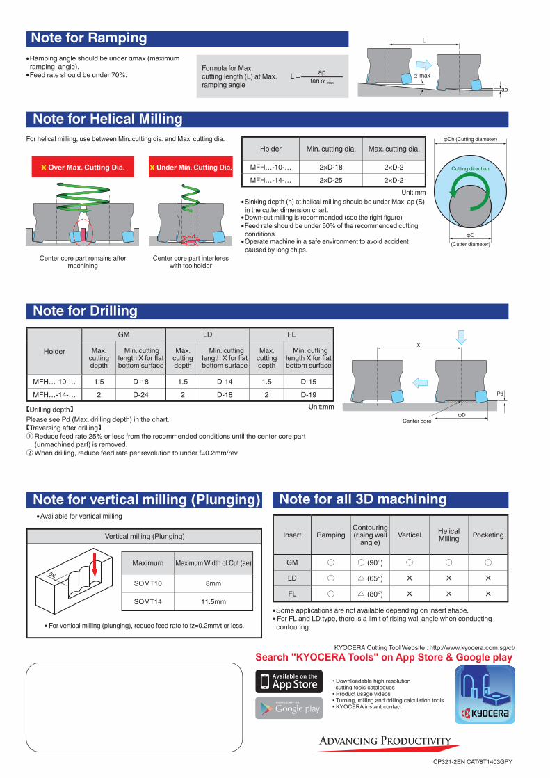
Note for Helical MillingFor helical milling, use between Min. cutting dia. and Max. cutting dia.
● Sinking depth (h) at helical milling should be under Max. ap (S)in the cutter dimension chart.
● Down-cut milling is recommended (see the right fi gure)● Feed rate should be under 50% of the recommended cutting
conditions.● Operate machine in a safe environment to avoid accident
caused by long chips.
Holder Min. cutting dia. Max. cutting dia.
MFH…-10-… 2×D-18 2×D-2
MFH…-14-… 2×D-25 2×D-2
x Over Max. Cutting Dia.
Center core part remains after machining
x Under Min. Cutting Dia.
Center core part interferes with toolholder
φDh (Cutting diameter)
φD(Cutter diameter)
Cutting direction
Note for Drilling
Note for vertical milling (Plunging) Note for all 3D machining
【Drilling depth】Please see Pd (Max. drilling depth) in the chart.【Traversing after drilling】① Reduce feed rate 25% or less from the recommended conditions until the center core part
(unmachined part) is removed.② When drilling, reduce feed rate per revolution to under f=0.2mm/rev.
X
φD
Pd
Center core
Holder
GM LD FL
Max. cutting depth
Min. cutting length X for fl at bottom surface
Max. cutting depth
Min. cutting length X for fl at bottom surface
Max. cutting depth
Min. cutting length X for fl at bottom surface
MFH…-10-… 1.5 D-18 1.5 D-14 1.5 D-15
MFH…-14-… 2 D-24 2 D-18 2 D-19 Unit:mm
Insert RampingContouring(rising wall
angle)Vertical Helical
Milling Pocketing
GM ○ ○ (90°) ○ ○ ○
LD ○ △ (65°) × × ×
FL ○ △ (80°) × × ×
Unit:mm
● Available for vertical milling
Vertical milling (Plunging)
Maximum Maximum Width of Cut (ae)
SOMT10 8mm
SOMT14 11.5mm
Note for Ramping● Ramping angle should be under αmax (maximum
ramping angle).● Feed rate should be under 70%.
Formula for Max. cutting length (L) at Max. ramping angle
ap
α max
L
● For vertical milling (plunging), reduce feed rate to fz=0.2mm/t or less.
● Some applications are not available depending on insert shape.● For FL and LD type, there is a limit of rising wall angle when conducting
contouring.
L = aptan α max