Embed Size (px)
Citation preview

Processes
Description
MIG (GMAW) Welding
Flux Cored (FCAW) Welding
Arc Welding Power Source
and Wire Feeder
OM-230 693L 2011−08
Millermatic 252�
File: MIG (GMAW)Visit our website at
www.MillerWelds.com

Miller Electric manufactures a full lineof welders and welding related equipment.For information on other quality Millerproducts, contact your local Miller distributor to receive the latest fullline catalog or individual specification sheets. To locate your nearestdistributor or service agency call 1-800-4-A-Miller, or visit us atwww.MillerWelds.com on the web.
Thank you and congratulations on choosing Miller. Now you can getthe job done and get it done right. We know you don’t have time to doit any other way.
That’s why when Niels Miller first started building arc welders in 1929,he made sure his products offered long-lasting value and superiorquality. Like you, his customers couldn’t afford anything less. Millerproducts had to be more than the best they could be. They had to be thebest you could buy.
Today, the people that build and sell Miller products continue thetradition. They’re just as committed to providing equipment and servicethat meets the high standards of quality and value established in 1929.
This Owner’s Manual is designed to help you get the most out of yourMiller products. Please take time to read the Safety precautions. Theywill help you protect yourself against potential hazards on the worksite.
We’ve made installation and operation quickand easy. With Miller you can count on yearsof reliable service with proper maintenance.And if for some reason the unit needs repair,there’s a Troubleshooting section that willhelp you figure out what the problem is. Theparts list will then help you to decide theexact part you may need to fix the problem.Warranty and service information for yourparticular model are also provided.
Miller is the first weldingequipment manufacturer inthe U.S.A. to be registered tothe ISO 9001 Quality SystemStandard.
Working as hard as you do− every power source fromMiller is backed by the mosthassle-free warranty in thebusiness.
From Miller to You
Mil_Thank 2009−09
3
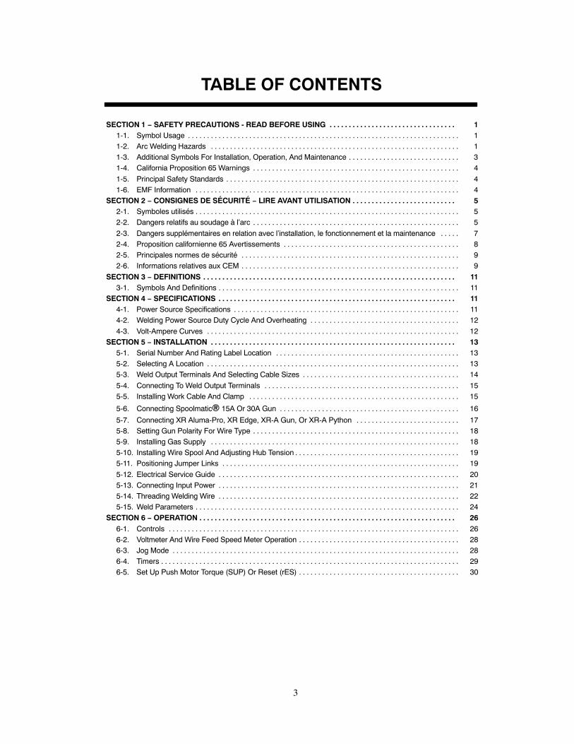
TABLE OF CONTENTS
SECTION 1 − SAFETY PRECAUTIONS - READ BEFORE USING 1. . . . . . . . . . . . . . . . . . . . . . . . . . . . . . . . .1-1. Symbol Usage 1. . . . . . . . . . . . . . . . . . . . . . . . . . . . . . . . . . . . . . . . . . . . . . . . . . . . . . . . . . . . . . . . . . . . . . .1-2. Arc Welding Hazards 1. . . . . . . . . . . . . . . . . . . . . . . . . . . . . . . . . . . . . . . . . . . . . . . . . . . . . . . . . . . . . . . . .1-3. Additional Symbols For Installation, Operation, And Maintenance 3. . . . . . . . . . . . . . . . . . . . . . . . . . . . .1-4. California Proposition 65 Warnings 4. . . . . . . . . . . . . . . . . . . . . . . . . . . . . . . . . . . . . . . . . . . . . . . . . . . . . .
1-5. Principal Safety Standards 4. . . . . . . . . . . . . . . . . . . . . . . . . . . . . . . . . . . . . . . . . . . . . . . . . . . . . . . . . . . . .1-6. EMF Information 4. . . . . . . . . . . . . . . . . . . . . . . . . . . . . . . . . . . . . . . . . . . . . . . . . . . . . . . . . . . . . . . . . . . . .
SECTION 2 − CONSIGNES DE SÉCURITÉ − LIRE AVANT UTILISATION 5. . . . . . . . . . . . . . . . . . . . . . . . . . .2-1. Symboles utilisés 5. . . . . . . . . . . . . . . . . . . . . . . . . . . . . . . . . . . . . . . . . . . . . . . . . . . . . . . . . . . . . . . . . . . . .2-2. Dangers relatifs au soudage à l’arc 5. . . . . . . . . . . . . . . . . . . . . . . . . . . . . . . . . . . . . . . . . . . . . . . . . . . . . .
2-3. Dangers supplémentaires en relation avec l’installation, le fonctionnement et la maintenance 7. . . . .2-4. Proposition californienne 65 Avertissements 8. . . . . . . . . . . . . . . . . . . . . . . . . . . . . . . . . . . . . . . . . . . . . .2-5. Principales normes de sécurité 9. . . . . . . . . . . . . . . . . . . . . . . . . . . . . . . . . . . . . . . . . . . . . . . . . . . . . . . . .2-6. Informations relatives aux CEM 9. . . . . . . . . . . . . . . . . . . . . . . . . . . . . . . . . . . . . . . . . . . . . . . . . . . . . . . . .
SECTION 3 − DEFINITIONS 11. . . . . . . . . . . . . . . . . . . . . . . . . . . . . . . . . . . . . . . . . . . . . . . . . . . . . . . . . . . . . . . . . .3-1. Symbols And Definitions 11. . . . . . . . . . . . . . . . . . . . . . . . . . . . . . . . . . . . . . . . . . . . . . . . . . . . . . . . . . . . . . .
SECTION 4 − SPECIFICATIONS 11. . . . . . . . . . . . . . . . . . . . . . . . . . . . . . . . . . . . . . . . . . . . . . . . . . . . . . . . . . . . . .4-1. Power Source Specifications 11. . . . . . . . . . . . . . . . . . . . . . . . . . . . . . . . . . . . . . . . . . . . . . . . . . . . . . . . . . .4-2. Welding Power Source Duty Cycle And Overheating 12. . . . . . . . . . . . . . . . . . . . . . . . . . . . . . . . . . . . . . .
4-3. Volt-Ampere Curves 12. . . . . . . . . . . . . . . . . . . . . . . . . . . . . . . . . . . . . . . . . . . . . . . . . . . . . . . . . . . . . . . . . .SECTION 5 − INSTALLATION 13. . . . . . . . . . . . . . . . . . . . . . . . . . . . . . . . . . . . . . . . . . . . . . . . . . . . . . . . . . . . . . . .
5-1. Serial Number And Rating Label Location 13. . . . . . . . . . . . . . . . . . . . . . . . . . . . . . . . . . . . . . . . . . . . . . . .5-2. Selecting A Location 13. . . . . . . . . . . . . . . . . . . . . . . . . . . . . . . . . . . . . . . . . . . . . . . . . . . . . . . . . . . . . . . . . .5-3. Weld Output Terminals And Selecting Cable Sizes 14. . . . . . . . . . . . . . . . . . . . . . . . . . . . . . . . . . . . . . . . .
5-4. Connecting To Weld Output Terminals 15. . . . . . . . . . . . . . . . . . . . . . . . . . . . . . . . . . . . . . . . . . . . . . . . . . .5-5. Installing Work Cable And Clamp 15. . . . . . . . . . . . . . . . . . . . . . . . . . . . . . . . . . . . . . . . . . . . . . . . . . . . . . .
5-6. Connecting Spoolmatic� 15A Or 30A Gun 16. . . . . . . . . . . . . . . . . . . . . . . . . . . . . . . . . . . . . . . . . . . . . . .
5-7. Connecting XR Aluma-Pro, XR Edge, XR-A Gun, Or XR-A Python 17. . . . . . . . . . . . . . . . . . . . . . . . . . .5-8. Setting Gun Polarity For Wire Type 18. . . . . . . . . . . . . . . . . . . . . . . . . . . . . . . . . . . . . . . . . . . . . . . . . . . . . .5-9. Installing Gas Supply 18. . . . . . . . . . . . . . . . . . . . . . . . . . . . . . . . . . . . . . . . . . . . . . . . . . . . . . . . . . . . . . . . .5-10. Installing Wire Spool And Adjusting Hub Tension 19. . . . . . . . . . . . . . . . . . . . . . . . . . . . . . . . . . . . . . . . . . .5-11. Positioning Jumper Links 19. . . . . . . . . . . . . . . . . . . . . . . . . . . . . . . . . . . . . . . . . . . . . . . . . . . . . . . . . . . . . .
5-12. Electrical Service Guide 20. . . . . . . . . . . . . . . . . . . . . . . . . . . . . . . . . . . . . . . . . . . . . . . . . . . . . . . . . . . . . . .5-13. Connecting Input Power 21. . . . . . . . . . . . . . . . . . . . . . . . . . . . . . . . . . . . . . . . . . . . . . . . . . . . . . . . . . . . . . .5-14. Threading Welding Wire 22. . . . . . . . . . . . . . . . . . . . . . . . . . . . . . . . . . . . . . . . . . . . . . . . . . . . . . . . . . . . . . .5-15. Weld Parameters 24. . . . . . . . . . . . . . . . . . . . . . . . . . . . . . . . . . . . . . . . . . . . . . . . . . . . . . . . . . . . . . . . . . . . .
SECTION 6 − OPERATION 26. . . . . . . . . . . . . . . . . . . . . . . . . . . . . . . . . . . . . . . . . . . . . . . . . . . . . . . . . . . . . . . . . . .6-1. Controls 26. . . . . . . . . . . . . . . . . . . . . . . . . . . . . . . . . . . . . . . . . . . . . . . . . . . . . . . . . . . . . . . . . . . . . . . . . . . .6-2. Voltmeter And Wire Feed Speed Meter Operation 28. . . . . . . . . . . . . . . . . . . . . . . . . . . . . . . . . . . . . . . . . .6-3. Jog Mode 28. . . . . . . . . . . . . . . . . . . . . . . . . . . . . . . . . . . . . . . . . . . . . . . . . . . . . . . . . . . . . . . . . . . . . . . . . . .6-4. Timers 29. . . . . . . . . . . . . . . . . . . . . . . . . . . . . . . . . . . . . . . . . . . . . . . . . . . . . . . . . . . . . . . . . . . . . . . . . . . . . .6-5. Set Up Push Motor Torque (SUP) Or Reset (rES) 30. . . . . . . . . . . . . . . . . . . . . . . . . . . . . . . . . . . . . . . . . .

4
TABLE OF CONTENTS
SECTION 7 − MAINTENANCE &TROUBLESHOOTING 31. . . . . . . . . . . . . . . . . . . . . . . . . . . . . . . . . . . . . . . . . .7-1. Routine Maintenance 31. . . . . . . . . . . . . . . . . . . . . . . . . . . . . . . . . . . . . . . . . . . . . . . . . . . . . . . . . . . . . . . . .7-2. Unit Overload 31. . . . . . . . . . . . . . . . . . . . . . . . . . . . . . . . . . . . . . . . . . . . . . . . . . . . . . . . . . . . . . . . . . . . . . . .7-3. Changing Drive Roll and Wire Inlet Guide 31. . . . . . . . . . . . . . . . . . . . . . . . . . . . . . . . . . . . . . . . . . . . . . . .7-4. Aligning Drive Rolls and Wire Guide 32. . . . . . . . . . . . . . . . . . . . . . . . . . . . . . . . . . . . . . . . . . . . . . . . . . . . .
7-5. Troubleshooting 33. . . . . . . . . . . . . . . . . . . . . . . . . . . . . . . . . . . . . . . . . . . . . . . . . . . . . . . . . . . . . . . . . . . . . .SECTION 8 − ELECTRICAL DIAGRAM 38. . . . . . . . . . . . . . . . . . . . . . . . . . . . . . . . . . . . . . . . . . . . . . . . . . . . . . . .SECTION 9 − MIG WELDING (GMAW) GUIDELINES 40. . . . . . . . . . . . . . . . . . . . . . . . . . . . . . . . . . . . . . . . . . . .
9-1. Typical MIG Process Connections 40. . . . . . . . . . . . . . . . . . . . . . . . . . . . . . . . . . . . . . . . . . . . . . . . . . . . . .9-2. Typical MIG Process Control Settings 41. . . . . . . . . . . . . . . . . . . . . . . . . . . . . . . . . . . . . . . . . . . . . . . . . . . .
9-3. Holding And Positioning Welding Gun 42. . . . . . . . . . . . . . . . . . . . . . . . . . . . . . . . . . . . . . . . . . . . . . . . . . . .9-4. Conditions That Affect Weld Bead Shape 43. . . . . . . . . . . . . . . . . . . . . . . . . . . . . . . . . . . . . . . . . . . . . . . . .9-5. Gun Movement During Welding 44. . . . . . . . . . . . . . . . . . . . . . . . . . . . . . . . . . . . . . . . . . . . . . . . . . . . . . . . .9-6. Poor Weld Bead Characteristics 44. . . . . . . . . . . . . . . . . . . . . . . . . . . . . . . . . . . . . . . . . . . . . . . . . . . . . . . .
9-7. Good Weld Bead Characteristics 44. . . . . . . . . . . . . . . . . . . . . . . . . . . . . . . . . . . . . . . . . . . . . . . . . . . . . . . .9-8. Troubleshooting − Excessive Spatter 45. . . . . . . . . . . . . . . . . . . . . . . . . . . . . . . . . . . . . . . . . . . . . . . . . . . .9-9. Troubleshooting − Porosity 45. . . . . . . . . . . . . . . . . . . . . . . . . . . . . . . . . . . . . . . . . . . . . . . . . . . . . . . . . . . . .9-10. Troubleshooting − Excessive Penetration 45. . . . . . . . . . . . . . . . . . . . . . . . . . . . . . . . . . . . . . . . . . . . . . . . .9-11. Troubleshooting − Lack Of Penetration 46. . . . . . . . . . . . . . . . . . . . . . . . . . . . . . . . . . . . . . . . . . . . . . . . . . .
9-12. Troubleshooting − Incomplete Fusion 46. . . . . . . . . . . . . . . . . . . . . . . . . . . . . . . . . . . . . . . . . . . . . . . . . . . .9-13. Troubleshooting − Burn-Through 46. . . . . . . . . . . . . . . . . . . . . . . . . . . . . . . . . . . . . . . . . . . . . . . . . . . . . . . .9-14. Troubleshooting − Waviness Of Bead 47. . . . . . . . . . . . . . . . . . . . . . . . . . . . . . . . . . . . . . . . . . . . . . . . . . . .9-15. Troubleshooting − Distortion 47. . . . . . . . . . . . . . . . . . . . . . . . . . . . . . . . . . . . . . . . . . . . . . . . . . . . . . . . . . . .9-16. Common MIG Shielding Gases 48. . . . . . . . . . . . . . . . . . . . . . . . . . . . . . . . . . . . . . . . . . . . . . . . . . . . . . . . .
9-17. Troubleshooting Guide For Semiautomatic Welding Equipment 48. . . . . . . . . . . . . . . . . . . . . . . . . . . . . . .SECTION 10 − PARTS LIST 50. . . . . . . . . . . . . . . . . . . . . . . . . . . . . . . . . . . . . . . . . . . . . . . . . . . . . . . . . . . . . . . . . .WARRANTY
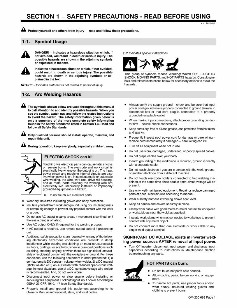
OM-230 693 Page 1
SECTION 1 − SAFETY PRECAUTIONS - READ BEFORE USINGsom 2011−01
7
Protect yourself and others from injury — read and follow these precautions.
1-1. Symbol Usage
DANGER! − Indicates a hazardous situation which, ifnot avoided, will result in death or serious injury. Thepossible hazards are shown in the adjoining symbolsor explained in the text.
Indicates a hazardous situation which, if not avoided,could result in death or serious injury. The possiblehazards are shown in the adjoining symbols or ex-plained in the text.
NOTICE − Indicates statements not related to personal injury.
� Indicates special instructions.
This group of symbols means Warning! Watch Out! ELECTRICSHOCK, MOVING PARTS, and HOT PARTS hazards. Consult sym-bols and related instructions below for necessary actions to avoid thehazards.
1-2. Arc Welding Hazards
The symbols shown below are used throughout this manualto call attention to and identify possible hazards. When yousee the symbol, watch out, and follow the related instructionsto avoid the hazard. The safety information given below isonly a summary of the more complete safety informationfound in the Safety Standards listed in Section 1-5. Read andfollow all Safety Standards.
Only qualified persons should install, operate, maintain, andrepair this unit.
During operation, keep everybody, especially children, away.
ELECTRIC SHOCK can kill.
Touching live electrical parts can cause fatal shocksor severe burns. The electrode and work circuit iselectrically live whenever the output is on. The inputpower circuit and machine internal circuits are alsolive when power is on. In semiautomatic or automaticwire welding, the wire, wire reel, drive roll housing,and all metal parts touching the welding wire areelectrically live. Incorrectly installed or improperlygrounded equipment is a hazard.
� Do not touch live electrical parts.
� Wear dry, hole-free insulating gloves and body protection.� Insulate yourself from work and ground using dry insulating mats
or covers big enough to prevent any physical contact with the workor ground.
� Do not use AC output in damp areas, if movement is confined, or ifthere is a danger of falling.
� Use AC output ONLY if required for the welding process.� If AC output is required, use remote output control if present on
unit.� Additional safety precautions are required when any of the follow-
ing electrically hazardous conditions are present: in damplocations or while wearing wet clothing; on metal structures suchas floors, gratings, or scaffolds; when in cramped positions suchas sitting, kneeling, or lying; or when there is a high risk of unavoid-able or accidental contact with the workpiece or ground. For theseconditions, use the following equipment in order presented: 1) asemiautomatic DC constant voltage (wire) welder, 2) a DC manual(stick) welder, or 3) an AC welder with reduced open-circuit volt-age. In most situations, use of a DC, constant voltage wire welderis recommended. And, do not work alone!
� Disconnect input power or stop engine before installing orservicing this equipment. Lockout/tagout input power according toOSHA 29 CFR 1910.147 (see Safety Standards).
� Properly install and ground this equipment according to itsOwner’s Manual and national, state, and local codes.
� Always verify the supply ground − check and be sure that inputpower cord ground wire is properly connected to ground terminal indisconnect box or that cord plug is connected to a properlygrounded receptacle outlet.
� When making input connections, attach proper grounding conduc-tor first − double-check connections.
� Keep cords dry, free of oil and grease, and protected from hot metaland sparks.
� Frequently inspect input power cord for damage or bare wiring −replace cord immediately if damaged − bare wiring can kill.
� Turn off all equipment when not in use.
� Do not use worn, damaged, undersized, or poorly spliced cables.
� Do not drape cables over your body.
� If earth grounding of the workpiece is required, ground it directlywith a separate cable.
� Do not touch electrode if you are in contact with the work, ground,or another electrode from a different machine.
� Do not touch electrode holders connected to two welding ma-chines at the same time since double open-circuit voltage will bepresent.
� Use only well-maintained equipment. Repair or replace damagedparts at once. Maintain unit according to manual.
� Wear a safety harness if working above floor level.
� Keep all panels and covers securely in place.
� Clamp work cable with good metal-to-metal contact to workpieceor worktable as near the weld as practical.
� Insulate work clamp when not connected to workpiece to preventcontact with any metal object.
� Do not connect more than one electrode or work cable to anysingle weld output terminal.
SIGNIFICANT DC VOLTAGE exists in inverter weld-ing power sources AFTER removal of input power.� Turn Off inverter, disconnect input power, and discharge input
capacitors according to instructions in Maintenance Sectionbefore touching any parts.
HOT PARTS can burn.
� Do not touch hot parts bare handed.� Allow cooling period before working on equip-
ment.� To handle hot parts, use proper tools and/or
wear heavy, insulated welding gloves andclothing to prevent burns.
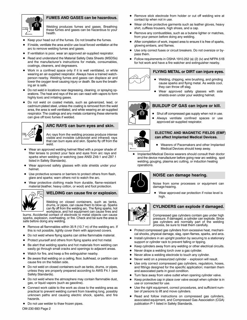
OM-230 693 Page 2
Welding produces fumes and gases. Breathingthese fumes and gases can be hazardous to yourhealth.
FUMES AND GASES can be hazardous.
� Keep your head out of the fumes. Do not breathe the fumes.
� If inside, ventilate the area and/or use local forced ventilation at thearc to remove welding fumes and gases.
� If ventilation is poor, wear an approved air-supplied respirator.
� Read and understand the Material Safety Data Sheets (MSDSs)and the manufacturer’s instructions for metals, consumables,coatings, cleaners, and degreasers.
� Work in a confined space only if it is well ventilated, or whilewearing an air-supplied respirator. Always have a trained watch-person nearby. Welding fumes and gases can displace air andlower the oxygen level causing injury or death. Be sure the breath-ing air is safe.
� Do not weld in locations near degreasing, cleaning, or spraying op-erations. The heat and rays of the arc can react with vapors to formhighly toxic and irritating gases.
� Do not weld on coated metals, such as galvanized, lead, orcadmium plated steel, unless the coating is removed from the weldarea, the area is well ventilated, and while wearing an air-suppliedrespirator. The coatings and any metals containing these elementscan give off toxic fumes if welded.
Arc rays from the welding process produce intensevisible and invisible (ultraviolet and infrared) raysthat can burn eyes and skin. Sparks fly off from theweld.
� Wear an approved welding helmet fitted with a proper shade offilter lenses to protect your face and eyes from arc rays andsparks when welding or watching (see ANSI Z49.1 and Z87.1listed in Safety Standards).
� Wear approved safety glasses with side shields under yourhelmet.
� Use protective screens or barriers to protect others from flash,glare and sparks; warn others not to watch the arc.
� Wear protective clothing made from durable, flame-resistantmaterial (leather, heavy cotton, or wool) and foot protection.
ARC RAYS can burn eyes and skin.
Welding on closed containers, such as tanks,drums, or pipes, can cause them to blow up. Sparkscan fly off from the welding arc. The flying sparks, hotworkpiece, and hot equipment can cause fires and
burns. Accidental contact of electrode to metal objects can causesparks, explosion, overheating, or fire. Check and be sure the area issafe before doing any welding.
WELDING can cause fire or explosion.
� Remove all flammables within 35 ft (10.7 m) of the welding arc. Ifthis is not possible, tightly cover them with approved covers.
� Do not weld where flying sparks can strike flammable material.
� Protect yourself and others from flying sparks and hot metal.
� Be alert that welding sparks and hot materials from welding caneasily go through small cracks and openings to adjacent areas.
� Watch for fire, and keep a fire extinguisher nearby.
� Be aware that welding on a ceiling, floor, bulkhead, or partition cancause fire on the hidden side.
� Do not weld on closed containers such as tanks, drums, or pipes,unless they are properly prepared according to AWS F4.1 (seeSafety Standards).
� Do not weld where the atmosphere may contain flammable dust,gas, or liquid vapors (such as gasoline).
� Connect work cable to the work as close to the welding area aspractical to prevent welding current from traveling long, possiblyunknown paths and causing electric shock, sparks, and firehazards.
� Do not use welder to thaw frozen pipes.
� Remove stick electrode from holder or cut off welding wire atcontact tip when not in use.
� Wear oil-free protective garments such as leather gloves, heavyshirt, cuffless trousers, high shoes, and a cap.
� Remove any combustibles, such as a butane lighter or matches,from your person before doing any welding.
� After completion of work, inspect area to ensure it is free of sparks,glowing embers, and flames.
� Use only correct fuses or circuit breakers. Do not oversize or by-pass them.
� Follow requirements in OSHA 1910.252 (a) (2) (iv) and NFPA 51Bfor hot work and have a fire watcher and extinguisher nearby.
FLYING METAL or DIRT can injure eyes.
� Welding, chipping, wire brushing, and grindingcause sparks and flying metal. As welds cool,they can throw off slag.
� Wear approved safety glasses with sideshields even under your welding helmet.
BUILDUP OF GAS can injure or kill.
� Shut off compressed gas supply when not in use.� Always ventilate confined spaces or use
approved air-supplied respirator.
ELECTRIC AND MAGNETIC FIELDS (EMF)can affect Implanted Medical Devices.
� Wearers of Pacemakers and other ImplantedMedical Devices should keep away.
� Implanted Medical Device wearers should consult their doctorand the device manufacturer before going near arc welding, spotwelding, gouging, plasma arc cutting, or induction heatingoperations.
NOISE can damage hearing.
Noise from some processes or equipment candamage hearing.
� Wear approved ear protection if noise level ishigh.
Compressed gas cylinders contain gas under highpressure. If damaged, a cylinder can explode. Sincegas cylinders are normally part of the weldingprocess, be sure to treat them carefully.
CYLINDERS can explode if damaged.
� Protect compressed gas cylinders from excessive heat, mechani-cal shocks, physical damage, slag, open flames, sparks, and arcs.
� Install cylinders in an upright position by securing to a stationarysupport or cylinder rack to prevent falling or tipping.
� Keep cylinders away from any welding or other electrical circuits.� Never drape a welding torch over a gas cylinder.� Never allow a welding electrode to touch any cylinder.� Never weld on a pressurized cylinder − explosion will result.� Use only correct compressed gas cylinders, regulators, hoses,
and fittings designed for the specific application; maintain themand associated parts in good condition.
� Turn face away from valve outlet when opening cylinder valve.� Keep protective cap in place over valve except when cylinder is in
use or connected for use.� Use the right equipment, correct procedures, and sufficient num-
ber of persons to lift and move cylinders.
� Read and follow instructions on compressed gas cylinders,associated equipment, and Compressed Gas Association (CGA)publication P-1 listed in Safety Standards.
OM-230 693 Page 3
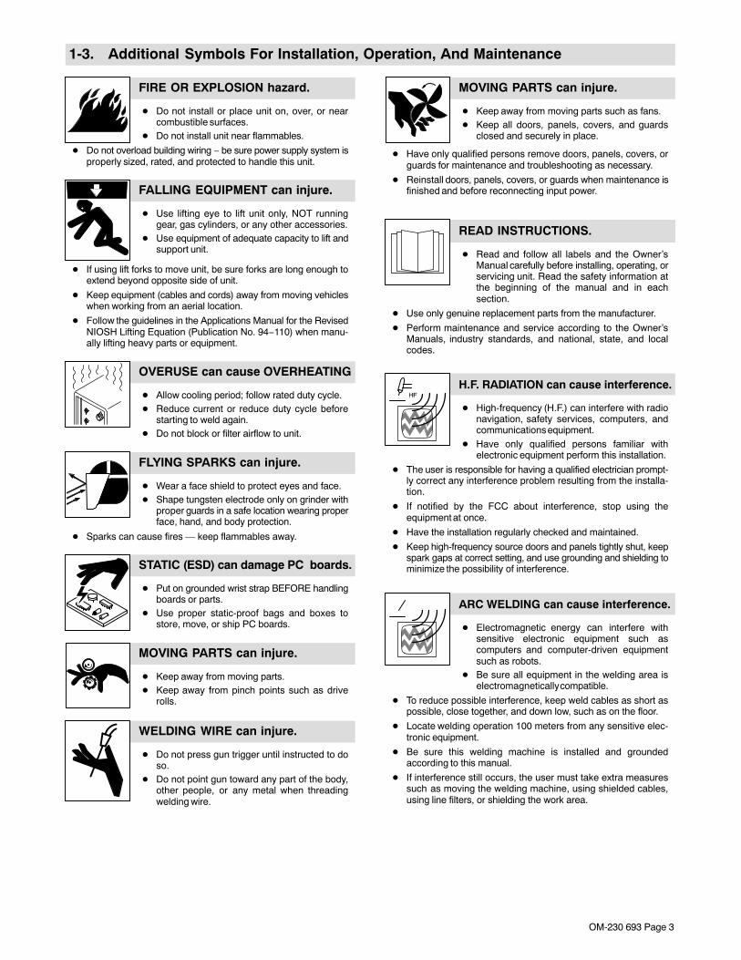
1-3. Additional Symbols For Installation, Operation, And Maintenance
FIRE OR EXPLOSION hazard.
� Do not install or place unit on, over, or nearcombustible surfaces.
� Do not install unit near flammables.
� Do not overload building wiring − be sure power supply system isproperly sized, rated, and protected to handle this unit.
FALLING EQUIPMENT can injure.
� Use lifting eye to lift unit only, NOT runninggear, gas cylinders, or any other accessories.
� Use equipment of adequate capacity to lift andsupport unit.
� If using lift forks to move unit, be sure forks are long enough toextend beyond opposite side of unit.
� Keep equipment (cables and cords) away from moving vehicleswhen working from an aerial location.
� Follow the guidelines in the Applications Manual for the RevisedNIOSH Lifting Equation (Publication No. 94−110) when manu-ally lifting heavy parts or equipment.
OVERUSE can cause OVERHEATING
� Allow cooling period; follow rated duty cycle.� Reduce current or reduce duty cycle before
starting to weld again.� Do not block or filter airflow to unit.
FLYING SPARKS can injure.
� Wear a face shield to protect eyes and face.� Shape tungsten electrode only on grinder with
proper guards in a safe location wearing properface, hand, and body protection.
� Sparks can cause fires — keep flammables away.
STATIC (ESD) can damage PC boards.
� Put on grounded wrist strap BEFORE handlingboards or parts.
� Use proper static-proof bags and boxes tostore, move, or ship PC boards.
MOVING PARTS can injure.
� Keep away from moving parts.� Keep away from pinch points such as drive
rolls.
WELDING WIRE can injure.
� Do not press gun trigger until instructed to doso.
� Do not point gun toward any part of the body,other people, or any metal when threadingwelding wire.
MOVING PARTS can injure.
� Keep away from moving parts such as fans.� Keep all doors, panels, covers, and guards
closed and securely in place.
� Have only qualified persons remove doors, panels, covers, orguards for maintenance and troubleshooting as necessary.
� Reinstall doors, panels, covers, or guards when maintenance isfinished and before reconnecting input power.
READ INSTRUCTIONS.
� Read and follow all labels and the Owner’sManual carefully before installing, operating, orservicing unit. Read the safety information atthe beginning of the manual and in eachsection.
� Use only genuine replacement parts from the manufacturer.
� Perform maintenance and service according to the Owner’sManuals, industry standards, and national, state, and localcodes.
H.F. RADIATION can cause interference.
� High-frequency (H.F.) can interfere with radionavigation, safety services, computers, andcommunications equipment.
� Have only qualified persons familiar withelectronic equipment perform this installation.
� The user is responsible for having a qualified electrician prompt-ly correct any interference problem resulting from the installa-tion.
� If notified by the FCC about interference, stop using theequipment at once.
� Have the installation regularly checked and maintained.
� Keep high-frequency source doors and panels tightly shut, keepspark gaps at correct setting, and use grounding and shielding tominimize the possibility of interference.
ARC WELDING can cause interference.
� Electromagnetic energy can interfere withsensitive electronic equipment such ascomputers and computer-driven equipmentsuch as robots.
� Be sure all equipment in the welding area iselectromagnetically compatible.
� To reduce possible interference, keep weld cables as short aspossible, close together, and down low, such as on the floor.
� Locate welding operation 100 meters from any sensitive elec-tronic equipment.
� Be sure this welding machine is installed and groundedaccording to this manual.
� If interference still occurs, the user must take extra measuressuch as moving the welding machine, using shielded cables,using line filters, or shielding the work area.
OM-230 693 Page 4
1-4. California Proposition 65 Warnings
Welding or cutting equipment produces fumes or gaseswhich contain chemicals known to the State of California tocause birth defects and, in some cases, cancer. (CaliforniaHealth & Safety Code Section 25249.5 et seq.)
Battery posts, terminals and related accessories contain leadand lead compounds, chemicals known to the State ofCalifornia to cause cancer and birth defects or otherreproductive harm. Wash hands after handling.
This product contains chemicals, including lead, known tothe state of California to cause cancer, birth defects, or otherreproductive harm. Wash hands after use.
For Gasoline Engines:
Engine exhaust contains chemicals known to the State ofCalifornia to cause cancer, birth defects, or other reproduc-tive harm.
For Diesel Engines:
Diesel engine exhaust and some of its constituents areknown to the State of California to cause cancer, birthdefects, and other reproductive harm.
1-5. Principal Safety Standards
Safety in Welding, Cutting, and Allied Processes, ANSI Standard Z49.1,from Global Engineering Documents (phone: 1-877-413-5184, website:www.global.ihs.com).Safe Practices for the Preparation of Containers and Piping for Weldingand Cutting, American Welding Society Standard AWS F4.1, from Glob-al Engineering Documents (phone: 1-877-413-5184, website:www.global.ihs.com).National Electrical Code, NFPA Standard 70, from National Fire Protec-tion Association, Quincy, MA 02269 (phone: 1-800-344-3555, website:www.nfpa.org and www. sparky.org).Safe Handling of Compressed Gases in Cylinders, CGA Pamphlet P-1,from Compressed Gas Association, 4221 Walney Road, 5th Floor,Chantilly, VA 20151 (phone: 703-788-2700, website:www.cganet.com).Safety in Welding, Cutting, and Allied Processes, CSA StandardW117.2, from Canadian Standards Association, Standards Sales, 5060Spectrum Way, Suite 100, Ontario, Canada L4W 5NS (phone:800-463-6727, website: www.csa-international.org).Safe Practice For Occupational And Educational Eye And Face Protec-tion, ANSI Standard Z87.1, from American National Standards Institute,
25 West 43rd Street, New York, NY 10036 (phone: 212-642-4900, web-site: www.ansi.org).Standard for Fire Prevention During Welding, Cutting, and Other HotWork, NFPA Standard 51B, from National Fire Protection Association,Quincy, MA 02269 (phone: 1-800-344-3555, website: www.nfpa.org.OSHA, Occupational Safety and Health Standards for General Indus-try, Title 29, Code of Federal Regulations (CFR), Part 1910, Subpart Q,and Part 1926, Subpart J, from U.S. Government Printing Office, Super-intendent of Documents, P.O. Box 371954, Pittsburgh, PA 15250-7954(phone: 1-866-512-1800) (there are 10 OSHA Regional Offices—phone for Region 5, Chicago, is 312-353-2220, website:www.osha.gov).U.S. Consumer Product Safety Commission (CPSC), 4330 East WestHighway, Bethesda, MD 20814 (phone: 301-504-7923, website:www.cpsc.gov).Applications Manual for the Revised NIOSH Lifting Equation, The Na-tional Institute for Occupational Safety and Health (NIOSH), 1600Clifton Rd, Atlanta, GA 30333 (phone: 1-800-232-4636, website:www.cdc.gov/NIOSH).
1-6. EMF Information
Electric current flowing through any conductor causes localized electricand magnetic fields (EMF). Welding current creates an EMF fieldaround the welding circuit and welding equipment. EMF fields may inter-fere with some medical implants, e.g. pacemakers. Protectivemeasures for persons wearing medical implants have to be taken. Forexample, access restrictions for passers−by or individual risk assess-ment for welders. All welders should use the following procedures inorder to minimize exposure to EMF fields from the welding circuit:
1. Keep cables close together by twisting or taping them, or using acable cover.
2. Do not place your body between welding cables. Arrange cablesto one side and away from the operator.
3. Do not coil or drape cables around your body.
4. Keep head and trunk as far away from the equipment in thewelding circuit as possible.
5. Connect work clamp to workpiece as close to the weld aspossible.
6. Do not work next to, sit or lean on the welding power source.
7. Do not weld whilst carrying the welding power source or wirefeeder.
About Implanted Medical Devices:Implanted Medical Device wearers should consult their doctor and thedevice manufacturer before performing or going near arc welding, spotwelding, gouging, plasma arc cutting, or induction heating operations.If cleared by your doctor, then following the above procedures is recom-mended.
OM-230 693 Page 5
SECTION 2 − CONSIGNES DE SÉCURITÉ − LIRE AVANT UTILISATION
fre_som_2011−017
Se protéger et protéger les autres contre le risque de blessure — lire et respecter ces consignes.
2-1. Symboles utilisés
DANGER! − Indique une situation dangereuse qui si onl’évite pas peut donner la mort ou des blessures graves.Les dangers possibles sont montrés par les symbolesjoints ou sont expliqués dans le texte.
Indique une situation dangereuse qui si on l’évite paspeut donner la mort ou des blessures graves. Les dan-gers possibles sont montrés par les symboles joints ousont expliqués dans le texte.
NOTE − Indique des déclarations pas en relation avec des blessurespersonnelles.
� Indique des instructions spécifiques.
Ce groupe de symboles veut dire Avertissement! Attention! DANGERDE CHOC ELECTRIQUE, PIECES EN MOUVEMENT, et PIECESCHAUDES. Consulter les symboles et les instructions ci-dessous yafférant pour les actions nécessaires afin d’éviter le danger.
2-2. Dangers relatifs au soudage à l’arc
Les symboles représentés ci-dessous sont utilisés dans ce ma-nuel pour attirer l’attention et identifier les dangers possibles. Enprésence de l’un de ces symboles, prendre garde et suivre lesinstructions afférentes pour éviter tout risque. Les instructionsen matière de sécurité indiquées ci-dessous ne constituentqu’un sommaire des instructions de sécurité plus complètesfournies dans les normes de sécurité énumérées dans la Sec-tion 2-5. Lire et observer toutes les normes de sécurité.
Seul un personnel qualifié est autorisé à installer, faire fonc-tionner, entretenir et réparer cet appareil.
Pendant le fonctionnement, maintenir à distance toutes lespersonnes, notamment les enfants de l’appareil.
UNE DÉCHARGE ÉLECTRIQUE peutentraîner la mort.Le contact d’organes électriques sous tension peutprovoquer des accidents mortels ou des brûluresgraves. Le circuit de l’électrode et de la pièce estsous tension lorsque le courant est délivré à lasortie. Le circuit d’alimentation et les circuits inter-nes de la machine sont également sous tensionlorsque l’alimentation est sur Marche. Dans le modede soudage avec du fil, le fil, le dérouleur, le bloc decommande du rouleau et toutes les parties métalli-ques en contact avec le fil sont sous tensionélectrique. Un équipement installé ou mis à la terrede manière incorrecte ou impropre constitue undanger.
� Ne pas toucher aux pièces électriques sous tension.
� Porter des gants isolants et des vêtements de protection secs etsans trous.
� S’isoler de la pièce à couper et du sol en utilisant des housses oudes tapis assez grands afin d’éviter tout contact physique avec lapièce à couper ou le sol.
� Ne pas se servir de source électrique à courant électrique dans leszones humides, dans les endroits confinés ou là où on risque detomber.
� Se servir d’une source électrique à courant électrique UNIQUE-MENT si le procédé de soudage le demande.
� Si l’utilisation d’une source électrique à courant électrique s’avèrenécessaire, se servir de la fonction de télécommande si l’appareilen est équipé.
� D’autres consignes de sécurité sont nécessaires dans les condi-tions suivantes : risques électriques dans un environnementhumide ou si l’on porte des vêtements mouillés ; sur des structuresmétalliques telles que sols, grilles ou échafaudages ; en positioncoincée comme assise, à genoux ou couchée ; ou s’il y a un risqueélevé de contact inévitable ou accidentel avec la pièce à souder oule sol. Dans ces conditions, utiliser les équipements suivants,
dans l’ordre indiqué : 1) un poste à souder DC à tension constante(à fil), 2) un poste à souder DC manuel (électrode) ou 3) un poste àsouder AC à tension à vide réduite. Dans la plupart des situations,l’utilisation d’un poste à souder DC à fil à tension constante est re-commandée. En outre, ne pas travailler seul !
� Couper l’alimentation ou arrêter le moteur avant de procéder à l’in-stallation, à la réparation ou à l’entretien de l’appareil. Déverrouillerl’alimentation selon la norme OSHA 29 CFR 1910.147 (voir nor-mes de sécurité).
� Installer le poste correctement et le mettre à la terre convenable-ment selon les consignes du manuel de l’opérateur et les normesnationales, provinciales et locales.
� Toujours vérifier la terre du cordon d’alimentation. Vérifier ets’assurer que le fil de terre du cordon d’alimentation est bienraccordé à la borne de terre du sectionneur ou que la fiche ducordon est raccordée à une prise correctement mise à la terre.
� En effectuant les raccordements d’entrée, fixer d’abord le conduc-teur de mise à la terre approprié et contre-vérifier les connexions.
� Les câbles doivent être exempts d’humidité, d’huile et de graisse;protégez−les contre les étincelles et les pièces métalliqueschaudes.
� Vérifier fréquemment le cordon d’alimentation afin de s’assurerqu’il n’est pas altéré ou à nu, le remplacer immédiatement s’il l’est.Un fil à nu peut entraîner la mort.
� L’équipement doit être hors tension lorsqu’il n’est pas utilisé.
� Ne pas utiliser des câbles usés, endommagés, de grosseur insuffi-sante ou mal épissés.
� Ne pas enrouler les câbles autour du corps.
� Si la pièce soudée doit être mise à la terre, le faire directementavec un câble distinct.
� Ne pas toucher l’électrode quand on est en contact avec la pièce,la terre ou une électrode provenant d’une autre machine.
� Ne pas toucher des porte électrodes connectés à deux machinesen même temps à cause de la présence d’une tension à vide dou-blée.
� N’utiliser qu’un matériel en bon état. Réparer ou remplacer sur-le-champ les pièces endommagées. Entretenir l’appareil conformé-ment à ce manuel.
� Porter un harnais de sécurité si l’on doit travailler au-dessus du sol.
� S’assurer que tous les panneaux et couvercles sont correctementen place.
� Fixer le câble de retour de façon à obtenir un bon contact métal-métal avec la pièce à souder ou la table de travail, le plus près pos-sible de la soudure.
� Isoler la pince de masse quand pas mis à la pièce pour éviter lecontact avec tout objet métallique.
� Ne pas raccorder plus d’une électrode ou plus d’un câble demasse à une même borne de sortie de soudage.
OM-230 693 Page 6
Il reste une TENSION DC NON NÉGLIGEABLE dansles sources de soudage onduleur UNE FOISl’alimentation coupée.� Arrêter les convertisseurs, débrancher le courant électrique et
décharger les condensateurs d’alimentation selon les instructionsindiquées dans la partie Entretien avant de toucher les pièces.
LES PIÈCES CHAUDES peuventprovoquer des brûlures.
� Ne pas toucher à mains nues les partieschaudes.
� Prévoir une période de refroidissement avant detravailler à l’équipement.
� Ne pas toucher aux pièces chaudes, utiliser les outils recomman-dés et porter des gants de soudage et des vêtements épais pouréviter les brûlures.
LES FUMÉES ET LES GAZ peuventêtre dangereux.
Le soudage génère des fumées et des gaz. Leurinhalation peut être dangereux pour votre santé.
� Eloigner votre tête des fumées. Ne pas respirer les fumées.
� À l’intérieur, ventiler la zone et/ou utiliser une ventilation forcée auniveau de l’arc pour l’évacuation des fumées et des gaz desoudage.
� Si la ventilation est médiocre, porter un respirateur anti-vapeursapprouvé.
� Lire et comprendre les spécifications de sécurité des matériaux(MSDS) et les instructions du fabricant concernant les métaux, lesconsommables, les revêtements, les nettoyants et les dégrais-seurs.
� Travailler dans un espace fermé seulement s’il est bien ventilé ouen portant un respirateur à alimentation d’air. Demander toujours àun surveillant dûment formé de se tenir à proximité. Des fumées etdes gaz de soudage peuvent déplacer l’air et abaisser le niveaud’oxygène provoquant des blessures ou des accidents mortels.S’assurer que l’air de respiration ne présente aucun danger.
� Ne pas souder dans des endroits situés à proximité d’opérationsde dégraissage, de nettoyage ou de pulvérisation. La chaleur etles rayons de l’arc peuvent réagir en présence de vapeurs et for-mer des gaz hautement toxiques et irritants.
� Ne pas souder des métaux munis d’un revêtement, tels que l’aciergalvanisé, plaqué en plomb ou au cadmium à moins que le revête-ment n’ait été enlevé dans la zone de soudure, que l’endroit soitbien ventilé, et en portant un respirateur à alimentation d’air. Lesrevêtements et tous les métaux renfermant ces éléments peuventdégager des fumées toxiques en cas de soudage.
LES RAYONS DE L’ARC peuventprovoquer des brûlures dans lesyeux et sur la peau.Le rayonnement de l’arc du procédé de soudagegénère des rayons visibles et invisibles intense
(ultraviolets et infrarouges) susceptibles de provoquer des brûluredans les yeux et sur la peau. Des étincelles sont projetées pendant lesoudage.
� Porter un casque de soudage approuvé muni de verres filtrantsapproprié pour protéger visage et yeux pour protéger votre visageet vos yeux pendant le soudage ou pour regarder (voir ANSI Z49.1et Z87.1 énuméré dans les normes de sécurité).
� Porter des lunettes de sécurité avec écrans latéraux même sousvotre casque.
� Avoir recours à des écrans protecteurs ou à des rideaux pourprotéger les autres contre les rayonnements les éblouissementset les étincelles ; prévenir toute personne sur les lieux de ne pasregarder l’arc.
� Porter des vêtements confectionnés avec des matières résistan-tes et ignifuges (cuir, coton lourd ou laine) et des bottes deprotection.
LE SOUDAGE peut provoquer unincendie ou une explosion.Le soudage effectué sur des conteneurs fermés telsque des réservoirs, tambours ou des conduites peutprovoquer leur éclatement. Des étincelles peuvent
être projetées de l’arc de soudure. La projection d’étincelles, despièces chaudes et des équipements chauds peut provoquer desincendies et des brûlures. Le contact accidentel de l’électrode avecdes objets métalliques peut provoquer des étincelles, une explosion,un surchauffement ou un incendie. Avant de commencer le soudage,vérifier et s’assurer que l’endroit ne présente pas de danger.
� Déplacer toutes les substances inflammables à une distance de10,7 m de l’arc de soudage. En cas d’impossibilité les recouvrirsoigneusement avec des protections homologués.
� Ne pas souder dans un endroit là où des étincelles peuvent tombersur des substances inflammables.
� Se protéger et d’autres personnes de la projection d’étincelles etde métal chaud.
� Des étincelles et des matériaux chauds du soudage peuventfacilement passer dans d’autres zones en traversant de petitesfissures et des ouvertures.
� Surveiller tout déclenchement d’incendie et tenir un extincteur àproximité.
� Le soudage effectué sur un plafond, plancher, paroi ou séparationpeut déclencher un incendie de l’autre côté.
� Ne pas effectuer le soudage sur des conteneurs fermés tels quedes réservoirs, tambours, ou conduites, à moins qu’ils n’aient étépréparés correctement conformément à AWS F4.1 (voir les nor-mes de sécurité).
� Ne soudez pas si l’air ambiant est chargé de particules, gaz, ou va-peurs inflammables (vapeur d’essence, par exemple).
� Brancher le câble de masse sur la pièce le plus près possible de lazone de soudage pour éviter le transport du courant sur unelongue distance par des chemins inconnus éventuels en provo-quant des risques d’électrocution, d’étincelles et d’incendie.
� Ne pas utiliser le poste de soudage pour dégeler des conduites ge-lées.
� En cas de non utilisation, enlever la baguette d’électrode du porte-électrode ou couper le fil à la pointe de contact.
� Porter des vêtements de protection dépourvus d’huile tels que desgants en cuir, une chemise en matériau lourd, des pantalons sansrevers, des chaussures hautes et un couvre chef.
� Avant de souder, retirer toute substance combustible de vos po-ches telles qu’un allumeur au butane ou des allumettes.
� Une fois le travail achevé, assurez−vous qu’il ne reste aucunetrace d’étincelles incandescentes ni de flammes.
� Utiliser exclusivement des fusibles ou coupe−circuits appropriés.Ne pas augmenter leur puissance; ne pas les ponter.
� Une fois le travail achevé, assurez−vous qu’il ne reste aucunetrace d’étincelles incandescentes ni de flammes.
� Utiliser exclusivement des fusibles ou coupe−circuits appropriés.Ne pas augmenter leur puissance; ne pas les ponter.
� Suivre les recommandations dans OSHA 1910.252(a)(2)(iv) etNFPA 51B pour les travaux à chaud et avoir de la surveillance et unextincteur à proximité.
DES PIECES DE METAL ou DESSALETES peuvent provoquer desblessures dans les yeux.
� Le soudage, l’écaillement, le passage de la pièce à la brosse enfil de fer, et le meulage génèrent des étincelles et des particulesmétalliques volantes. Pendant la période de refroidissement dessoudures, elles risquent de projeter du laitier.
� Porter des lunettes de sécurité avec écrans latéraux ou un écranfacial.
OM-230 693 Page 7
LES ACCUMULATIONS DE GAZrisquent de provoquer des blessuresou même la mort.� Fermer l’alimentation du gaz comprimé en cas
de non utilisation.� Veiller toujours à bien aérer les espaces confi-
nés ou se servir d’un respirateur d’adductiond’air homologué.
Les CHAMPS ÉLECTROMAGNÉTIQUES (CEM)peuvent affecter les implants médicaux.
� Les porteurs de stimulateurs cardiaques etautres implants médicaux doivent rester àdistance.
� Les porteurs d’implants médicaux doivent consulter leurmédecin et le fabricant du dispositif avant de s’approcher de lazone où se déroule du soudage à l’arc, du soudage par points, dugougeage, de la découpe plasma ou une opération de chauffagepar induction.
LE BRUIT peut endommager l’ouïe.
Le bruit des processus et des équipements peutaffecter l’ouïe.
� Porter des protections approuvées pour lesoreilles si le niveau sonore est trop élevé.
Les bouteilles de gaz comprimé contiennent du gazsous haute pression. Si une bouteille estendommagée, elle peut exploser. Du fait que lesbouteilles de gaz font normalement partie duprocédé de soudage, les manipuler avecprécaution.
LES BOUTEILLES peuvent explosersi elles sont endommagées.
� Protéger les bouteilles de gaz comprimé d’une chaleur excessive,des chocs mécaniques, des dommages physiques, du laitier, desflammes ouvertes, des étincelles et des arcs.
� Placer les bouteilles debout en les fixant dans un support station-naire ou dans un porte-bouteilles pour les empêcher de tomber oude se renverser.
� Tenir les bouteilles éloignées des circuits de soudage ou autrescircuits électriques.
� Ne jamais placer une torche de soudage sur une bouteille à gaz.
� Une électrode de soudage ne doit jamais entrer en contact avecune bouteille.
� Ne jamais souder une bouteille pressurisée − risque d’explosion.
� Utiliser seulement des bouteilles de gaz comprimé, régulateurs,tuyaux et raccords convenables pour cette application spécifique;les maintenir ainsi que les éléments associés en bon état.
� Détourner votre visage du détendeur-régulateur lorsque vousouvrez la soupape de la bouteille.
� Le couvercle du détendeur doit toujours être en place, sauf lorsquela bouteille est utilisée ou qu’elle est reliée pour usage ultérieur.
� Utiliser les équipements corrects, les bonnes procédures et suffi-samment de personnes pour soulever et déplacer les bouteilles.
� Lire et suivre les instructions sur les bouteilles de gaz comprimé,l’équipement connexe et le dépliant P-1 de la CGA (CompressedGas Association) mentionné dans les principales normes de sécu-rité.
2-3. Dangers supplémentaires en relation avec l’installation, le fonctionnement et la maintenance
Risque D’INCENDIE OUD’EXPLOSION.� Ne pas placer l’appareil sur, au-dessus ou
à proximité de surfaces inflammables.� Ne pas installer l’appareil à proximité de pro-
duits inflammables.
� Ne pas surcharger l’installation électrique − s’assurer quel’alimentation est correctement dimensionnée et protégée avantde mettre l’appareil en service.
LA CHUTE DE L’ÉQUIPEMENT peutprovoquer des blessures.� Utiliser l’anneau de levage uniquement pour
soulever l’appareil, NON PAS les chariots, lesbouteilles de gaz ou tout autre accessoire.
� Utiliser un équipement de levage de capacitésuffisante pour lever l’appareil.
� En utilisant des fourches de levage pour déplacer l’unité, s’assu-rer que les fourches sont suffisamment longues pour dépasserdu côté opposé de l’appareil.
� Tenir l’équipement (câbles et cordons) à distance des véhiculesmobiles lors de toute opération en hauteur.
� Suivre les consignes du Manuel des applications pour l’équationde levage NIOSH révisée (Publication Nº94–110) lors du levagemanuelle de pièces ou équipements lourds.
L’EMPLOI EXCESSIF peutSURCHAUFFER L’ÉQUIPEMENT.� Prévoir une période de refroidissement ; res-
pecter le cycle opératoire nominal.� Réduire le courant ou le facteur de marche
avant de poursuivre le soudage.
� Ne pas obstruer les passages d’air du poste.
LES ÉTINCELLES PROJETÉESpeuvent provoquer des blessures.
� Porter un écran facial pour protéger le visage etles yeux.
� Affûter l’électrode au tungstène uniquement à lameuleuse dotée de protecteurs. Cettemanœuvre est à exécuter dans un endroit sûrlorsque l’on porte l’équipement homologué deprotection du visage, des mains et du corps.
� Les étincelles risquent de causer un incendie − éloigner toute sub-stance inflammable.
LES CHARGES ÉLECTROSTATI-QUES peuvent endommager les cir-cuits imprimés.
� Établir la connexion avec la barrette de terreavant de manipuler des cartes ou des pièces.
� Utiliser des pochettes et des boîtes antista-tiques pour stocker, déplacer ou expédier descartes de circuits imprimes.
OM-230 693 Page 8
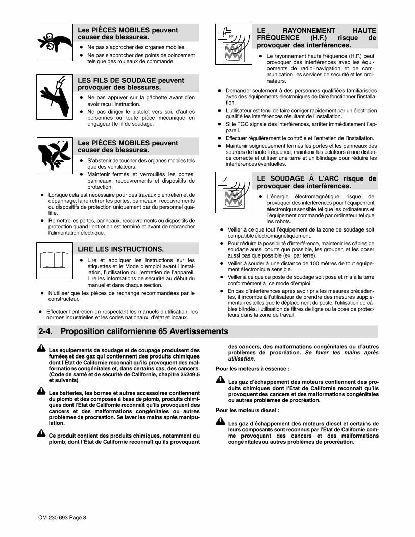
Les PIÈCES MOBILES peuventcauser des blessures.� Ne pas s’approcher des organes mobiles.� Ne pas s’approcher des points de coincement
tels que des rouleaux de commande.
LES FILS DE SOUDAGE peuventprovoquer des blessures.� Ne pas appuyer sur la gâchette avant d’en
avoir reçu l’instruction.� Ne pas diriger le pistolet vers soi, d’autres
personnes ou toute pièce mécanique enengageant le fil de soudage.
Les PIÈCES MOBILES peuventcauser des blessures.� S’abstenir de toucher des organes mobiles tels
que des ventilateurs.� Maintenir fermés et verrouillés les portes,
panneaux, recouvrements et dispositifs deprotection.
� Lorsque cela est nécessaire pour des travaux d’entretien et dedépannage, faire retirer les portes, panneaux, recouvrementsou dispositifs de protection uniquement par du personnel qua-lifié.
� Remettre les portes, panneaux, recouvrements ou dispositifs deprotection quand l’entretien est terminé et avant de rebrancherl’alimentation électrique.
LIRE LES INSTRUCTIONS.
� Lire et appliquer les instructions sur lesétiquettes et le Mode d’emploi avant l’instal-lation, l’utilisation ou l’entretien de l’appareil.Lire les informations de sécurité au début dumanuel et dans chaque section.
� N’utiliser que les pièces de rechange recommandées par leconstructeur.
� Effectuer l’entretien en respectant les manuels d’utilisation, lesnormes industrielles et les codes nationaux, d’état et locaux.
LE RAYONNEMENT HAUTEFRÉQUENCE (H.F.) risque deprovoquer des interférences.
� Le rayonnement haute fréquence (H.F.) peutprovoquer des interférences avec les équi-pements de radio−navigation et de com-munication, les services de sécurité et les ordi-nateurs.
� Demander seulement à des personnes qualifiées familiariséesavec des équipements électroniques de faire fonctionner l’installa-tion.
� L’utilisateur est tenu de faire corriger rapidement par un électricienqualifié les interférences résultant de l’installation.
� Si le FCC signale des interférences, arrêter immédiatement l’ap-pareil.
� Effectuer régulièrement le contrôle et l’entretien de l’installation.� Maintenir soigneusement fermés les portes et les panneaux des
sources de haute fréquence, maintenir les éclateurs à une distan-ce correcte et utiliser une terre et un blindage pour réduire lesinterférences éventuelles.
LE SOUDAGE À L’ARC risque deprovoquer des interférences.
� L’énergie électromagnétique risque deprovoquer des interférences pour l’équipementélectronique sensible tel que les ordinateurs etl’équipement commandé par ordinateur tel queles robots.
� Veiller à ce que tout l’équipement de la zone de soudage soitcompatible électromagnétiquement.
� Pour réduire la possibilité d’interférence, maintenir les câbles desoudage aussi courts que possible, les grouper, et les poseraussi bas que possible (ex. par terre).
� Veiller à souder à une distance de 100 mètres de tout équipe-ment électronique sensible.
� Veiller à ce que ce poste de soudage soit posé et mis à la terreconformément à ce mode d’emploi.
� En cas d’interférences après avoir pris les mesures précéden-tes, il incombe à l’utilisateur de prendre des mesures supplé-mentaires telles que le déplacement du poste, l’utilisation de câ-bles blindés, l’utilisation de filtres de ligne ou la pose de protec-teurs dans la zone de travail.
2-4. Proposition californienne 65 Avertissements
Les équipements de soudage et de coupage produisent desfumées et des gaz qui contiennent des produits chimiquesdont l’État de Californie reconnaît qu’ils provoquent des mal-formations congénitales et, dans certains cas, des cancers.(Code de santé et de sécurité de Californie, chapitre 25249.5et suivants)
Les batteries, les bornes et autres accessoires contiennentdu plomb et des composés à base de plomb, produits chimi-ques dont l’État de Californie reconnaît qu’ils provoquent descancers et des malformations congénitales ou autresproblèmes de procréation. Se laver les mains après manipu-lation.
Ce produit contient des produits chimiques, notamment duplomb, dont l’État de Californie reconnaît qu’ils provoquent
des cancers, des malformations congénitales ou d’autresproblèmes de procréation. Se laver les mains aprèsutilisation.
Pour les moteurs à essence :
Les gaz d’échappement des moteurs contiennent des pro-duits chimiques dont l’État de Californie reconnaît qu’ilsprovoquent des cancers et des malformations congénitalesou autres problèmes de procréation.
Pour les moteurs diesel :
Les gaz d’échappement des moteurs diesel et certains deleurs composants sont reconnus par l’État de Californie com-me provoquant des cancers et des malformationscongénitales ou autres problèmes de procréation.

OM-230 693 Page 9
2-5. Principales normes de sécuritéSafety in Welding, Cutting, and Allied Processes, ANSI Standard Z49.1,de Global Engineering Documents (téléphone : 1-877-413-5184, siteInternet : www.global.ihs.com).
Safe Practices for the Preparation of Containers and Piping for Weldingand Cutting, American Welding Society Standard AWS F4.1, de GlobalEngineering Documents (téléphone : 1-877-413-5184, site internet :www.global.ihs.com).National Electrical Code, NFPA Standard 70, de National Fire Protec-tion Association, Quincy, MA 02269 (téléphone : 800-344-3555, siteInternet : www.nfpa.org et www.sparky.org).
Safe Handling of Compressed Gases in Cylinders, CGA Pamphlet P-1,de Compressed Gas Association, 4221 Walney Road, 5th Floor, Chan-tilly, VA 20151 (téléphone : 703-788-2700, site Internet :www.cganet.com).
Safety in Welding, Cutting, and Allied Processes, CSA StandardW117.2, de Canadian Standards Association, Standards Sales, 5060Spectrum Way, Suite 100, Ontario, Canada L4W 5NS (téléphone :800-463-6727, site internet : www.csa-international.org).Safe Practice For Occupational And Educational Eye And Face Protec-tion, ANSI Standard Z87.1, de American National Standards Institute,
25 West 43rd Street, New York, NY 10036 (téléphone : 212-642-4900,site Internet : www.ansi.org).
Standard for Fire Prevention During Welding, Cutting, and Other HotWork, NFPA Standard 51B, de National Fire Protection Association,P.O. Box 9101, Quincy, MA 02269-9101 (téléphone : 617-770-3000,site Internet : www.nfpa.org).
OSHA, Occupational Safety and Health Standards for GeneralIndustry, Title 29, Code of Federal Regulations (CFR), Part 1910,Subpart Q, and Part 1926, Subpart J, de U.S. Government PrintingOffice, Superintendent of Documents, P.O. Box 371954, Pittsburgh, PA15250-7954 (téléphone : 1-866-512-1800) (il y a 10 bureauxrégionaux−le téléphone de la région 5, Chicago, est 312-353-2220, siteInternet : www.osha.gov).
U.S. Consumer Product Safety Commission (CPSC), 4330 East WestHighway, Bethesda, MD 20814 (téléphone : 301-504-7923, site inter-net : www.cpsc.gov).Applications Manual for the Revised NIOSH Lifting Equation, TheNational Institute for Occupational Safety and Health (NIOSH), 1600Clifton Rd, Atlanta, GA 30333 (télé[hone : 1-800-232-4636, site internet:www.cdc.gov/NIOSH).
2-6. Informations relatives aux CEM
Le courant électrique qui traverse tout conducteur génère des champsélectromagnétiques (CEM) à certains endroits. Le courant de soudagecrée un CEM autour du circuit et du matériel de soudage. Les CEMpeuvent créer des interférences avec certains implants médicauxcomme des stimulateurs cardiaques. Des mesures de protection pourles porteurs d’implants médicaux doivent être prises: par exemple, desrestrictions d’accès pour les passants ou une évaluation individuelledes risques pour les soudeurs. Tous les soudeurs doivent appliquer lesprocédures suivantes pour minimiser l’exposition aux CEM provenantdu circuit de soudage:
1. Rassembler les câbles en les torsadant ou en les attachant avecdu ruban adhésif ou avec une housse.
2. Ne pas se tenir au milieu des câbles de soudage. Disposer lescâbles d’un côté et à distance de l’opérateur.
3. Ne pas courber et ne pas entourer les câbles autour de votrecorps.
4. Maintenir la tête et le torse aussi loin que possible du matériel ducircuit de soudage.
5. Connecter la pince sur la pièce aussi près que possible de lasoudure.
6. Ne pas travailler à proximité d’une source de soudage, nis’asseoir ou se pencher dessus.
7. Ne pas souder tout en portant la source de soudage ou ledévidoir.
En ce qui concerne les implants médicaux :
Les porteurs d’implants doivent d’abord consulter leur médecin avantde s’approcher des opérations de soudage à l’arc, de soudage parpoints, de gougeage, du coupage plasma ou de chauffage par induc-tion. Si le médecin approuve, il est recommandé de suivre lesprocédures précédentes.

OM-230 693 Page 10
� A complete Parts List is available at www.MillerWelds.com
OM-230 693 Page 11
SECTION 3 − DEFINITIONS
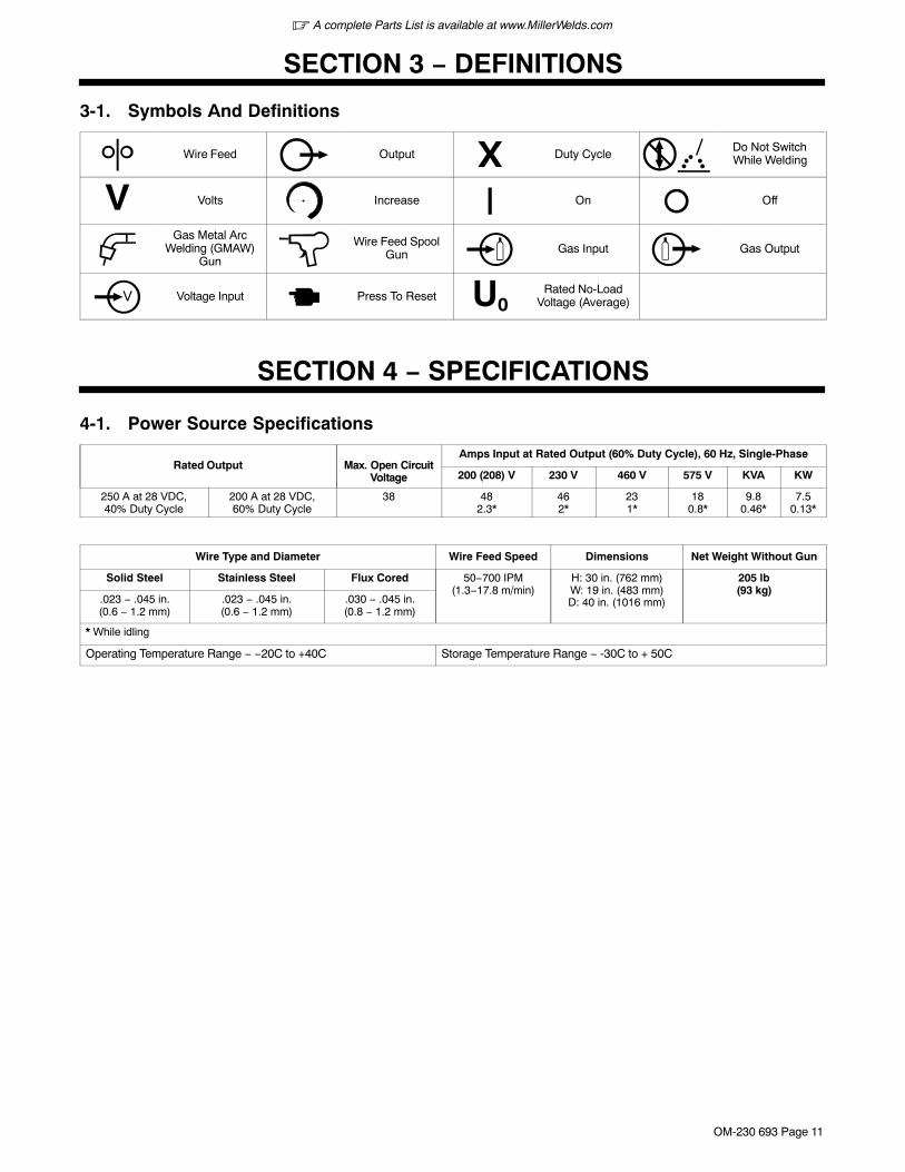
3-1. Symbols And Definitions
Wire Feed Output X Duty CycleDo Not SwitchWhile Welding
V Volts Increase On Off
Gas Metal ArcWelding (GMAW)
Gun
Wire Feed SpoolGun Gas Input Gas Output
Voltage Input Press To Reset U0Rated No-Load
Voltage (Average)
SECTION 4 − SPECIFICATIONS
4-1. Power Source Specifications
Rated Output Max. Open CircuitVoltage
Amps Input at Rated Output (60% Duty Cycle), 60 Hz, Single-Phase
200 (208) V 230 V 460 V 575 V KVA KW
250 A at 28 VDC,40% Duty Cycle
200 A at 28 VDC,60% Duty Cycle
38 482.3*
462*
231*
180.8*
9.80.46*
7.50.13*
Wire Type and Diameter Wire Feed Speed Dimensions Net Weight Without Gun
Solid Steel Stainless Steel Flux Cored 50−700 IPM(1.3−17.8 m/min)
H: 30 in. (762 mm)W: 19 in. (483 mm)D: 40 in. (1016 mm)
205 lb(93 kg)
.023 − .045 in.(0.6 − 1.2 mm)
.023 − .045 in.(0.6 − 1.2 mm)
.030 − .045 in.(0.8 − 1.2 mm)
* While idling
Operating Temperature Range − −20C to +40C Storage Temperature Range − -30C to + 50C
� A complete Parts List is available at www.MillerWelds.com
OM-230 693 Page 12
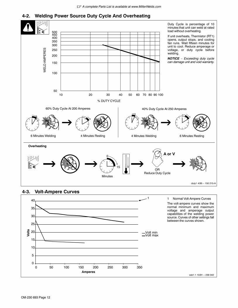
4-2. Welding Power Source Duty Cycle And Overheating
4 Minutes Welding 6 Minutes Resting6 Minutes Welding 4 Minutes Resting
Duty Cycle is percentage of 10minutes that unit can weld at ratedload without overheating.
If unit overheats, Thermistor (RT1)opens, output stops, and coolingfan runs. Wait fifteen minutes forunit to cool. Reduce amperage orvoltage, or duty cycle beforewelding.
NOTICE − Exceeding duty cyclecan damage unit and void warranty.
Overheating
0
15
A or V
ORReduce Duty Cycle
Minutes
duty1 4/95 − 150 215-A
40% Duty Cycle At 250 Amperes60% Duty Cycle At 200 Amperes
10 20 30 40 50 60 70 80 90 10050
100
150
200
250
300350400450500
% DUTY CYCLE
WE
LD A
MP
ER
ES
4-3. Volt-Ampere Curves
ssb1.1 10/91 − 239 342
1 Normal Volt-Ampere Curves
The volt-ampere curves show thenormal minimum and maximumvoltage and amperage outputcapabilities of the welding powersource. Curves of other settings fallbetween the curves shown.
1
0
5
10
15
20
25
30
35
40
0 50 100 150 200 250 300 350
Volt minVolt max
Amperes
Vo
lts
� A complete Parts List is available at www.MillerWelds.com
OM-230 693 Page 13
SECTION 5 − INSTALLATION5-1. Serial Number And Rating Label LocationThe serial number and rating information for this product is located on back. Use rating label to determine input power requirements and/or rated output.For future reference, write serial number in space provided on back cover of this manual.
5-2. Selecting A Location
loc_2 3/96 - Ref. 804 912-A
1 Line Disconnect Device
Locate unit near correct inputpower supply.
! Special installation may berequired where gasoline orvolatile liquids are present −see NEC Article 511 or CECSection 20.
Location
1
18 in.(460 mm)
18 in.(460 mm)
Tipping
! Do not move or operateunit where it could tip.
� A complete Parts List is available at www.MillerWelds.com
OM-230 693 Page 14
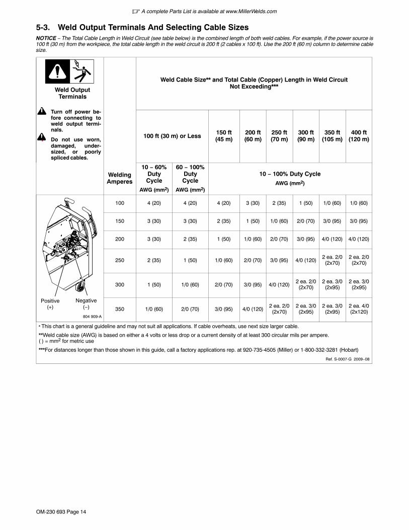
5-3. Weld Output Terminals And Selecting Cable SizesNOTICE − The Total Cable Length in Weld Circuit (see table below) is the combined length of both weld cables. For example, if the power source is100 ft (30 m) from the workpiece, the total cable length in the weld circuit is 200 ft (2 cables x 100 ft). Use the 200 ft (60 m) column to determine cablesize.
! Turn off power be-fore connecting toweld output termi-nals.
! Do not use worn,damaged, under-sized, or poorlyspliced cables.
Weld OutputTerminals
Weld Cable Size** and Total Cable (Copper) Length in Weld CircuitNot Exceeding***
100 ft (30 m) or Less 150 ft(45 m)
200 ft(60 m)
250 ft(70 m)
300 ft(90 m)
350 ft(105 m)
400 ft(120 m)
WeldingAmperes
10 − 60%DutyCycle
AWG (mm2)
60 − 100%DutyCycle
AWG (mm2)
10 − 100% Duty Cycle
AWG (mm2)
804 909-A
Positive Negative(+) (−)
100 4 (20) 4 (20) 4 (20) 3 (30) 2 (35) 1 (50) 1/0 (60) 1/0 (60)
150 3 (30) 3 (30) 2 (35) 1 (50) 1/0 (60) 2/0 (70) 3/0 (95) 3/0 (95)
200 3 (30) 2 (35) 1 (50) 1/0 (60) 2/0 (70) 3/0 (95) 4/0 (120) 4/0 (120)
250 2 (35) 1 (50) 1/0 (60) 2/0 (70) 3/0 (95) 4/0 (120)2 ea. 2/0(2x70)
2 ea. 2/0(2x70)
300 1 (50) 1/0 (60) 2/0 (70) 3/0 (95) 4/0 (120)2 ea. 2/0(2x70)
2 ea. 3/0(2x95)
2 ea. 3/0(2x95)
350 1/0 (60) 2/0 (70) 3/0 (95) 4/0 (120)2 ea. 2/0(2x70)
2 ea. 3/0(2x95)
2 ea. 3/0(2x95)
2 ea. 4/0(2x120)
* This chart is a general guideline and may not suit all applications. If cable overheats, use next size larger cable.
**Weld cable size (AWG) is based on either a 4 volts or less drop or a current density of at least 300 circular mils per ampere.( ) = mm2 for metric use
***For distances longer than those shown in this guide, call a factory applications rep. at 920-735-4505 (Miller) or 1-800-332-3281 (Hobart)
Ref. S-0007-G 2009−08
� A complete Parts List is available at www.MillerWelds.com
OM-230 693 Page 15
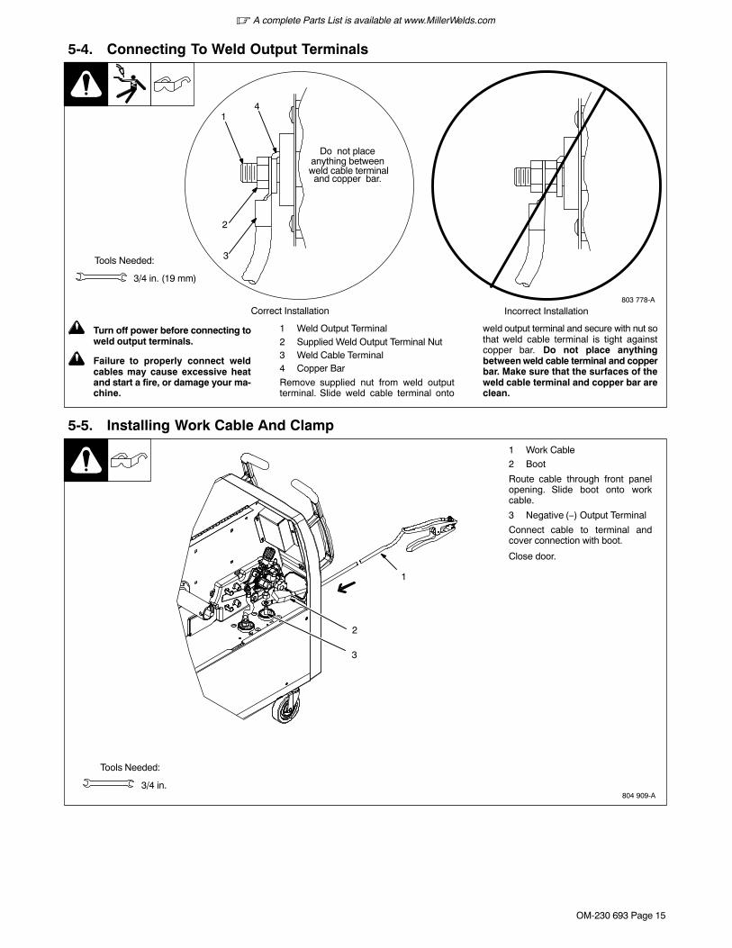
5-4. Connecting To Weld Output Terminals
803 778-A
! Turn off power before connecting toweld output terminals.
! Failure to properly connect weldcables may cause excessive heatand start a fire, or damage your ma-chine.
1 Weld Output Terminal2 Supplied Weld Output Terminal Nut3 Weld Cable Terminal4 Copper Bar
Remove supplied nut from weld outputterminal. Slide weld cable terminal onto
weld output terminal and secure with nut sothat weld cable terminal is tight againstcopper bar. Do not place anythingbetween weld cable terminal and copperbar. Make sure that the surfaces of theweld cable terminal and copper bar areclean.
Tools Needed:
3/4 in. (19 mm)
4
2
3
Do not placeanything between
Correct Installation Incorrect Installation
1
weld cable terminaland copper bar.
5-5. Installing Work Cable And Clamp
Tools Needed:
3/4 in.
1 Work Cable
2 Boot
Route cable through front panelopening. Slide boot onto workcable.
3 Negative (−) Output Terminal
Connect cable to terminal andcover connection with boot.
Close door.
2
3
1
804 909-A
� A complete Parts List is available at www.MillerWelds.com
OM-230 693 Page 16
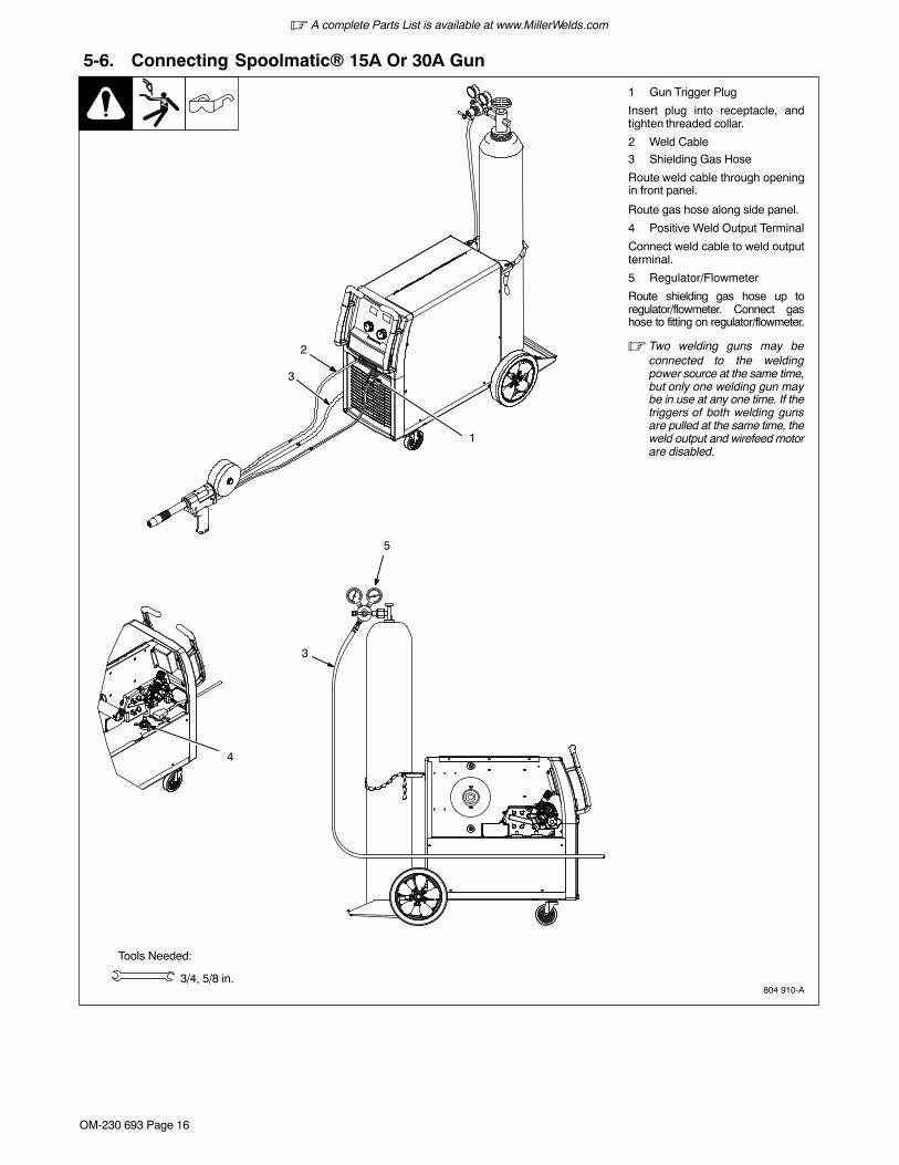
5-6. Connecting Spoolmatic� 15A Or 30A Gun
804 910-A
1 Gun Trigger Plug
Insert plug into receptacle, andtighten threaded collar.
2 Weld Cable
3 Shielding Gas Hose
Route weld cable through openingin front panel.
Route gas hose along side panel.
4 Positive Weld Output Terminal
Connect weld cable to weld outputterminal.
5 Regulator/Flowmeter
Route shielding gas hose up toregulator/flowmeter. Connect gashose to fitting on regulator/flowmeter.
� Two welding guns may beconnected to the weldingpower source at the same time,but only one welding gun maybe in use at any one time. If thetriggers of both welding gunsare pulled at the same time, theweld output and wirefeed motorare disabled.
Tools Needed:
3/4, 5/8 in.
5
3
4
1
3
2
� A complete Parts List is available at www.MillerWelds.com
OM-230 693 Page 17
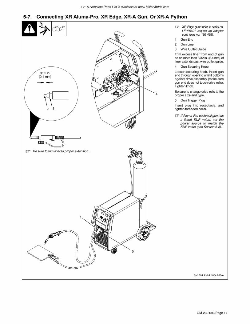
5-7. Connecting XR Aluma-Pro, XR Edge, XR-A Gun, Or XR-A Python
Ref. 804 910-A / 804 936-A
� XR Edge guns prior to serial no.LE079101 require an adaptercord (part no. 195 498).
1 Gun End
2 Gun Liner
3 Wire Outlet Guide
Trim excess liner from end of gunso no more than 3/32 in. (2.4 mm) ofliner extends past wire outlet guide.
4 Gun Securing Knob
Loosen securing knob. Insert gunend through opening until it bottomsagainst drive assembly (make suregun end does not touch drive rolls).Tighten knob.
Be sure to change drive rolls to theproper size and type.
5 Gun Trigger Plug
Insert plug into receptacle, andtighten threaded collar.
� If Aluma-Pro push/pull gun hasa listed SUP value, set thepower source to match theSUP value (see Section 6-5).
32
3/32 in.(2.4 mm)
� Be sure to trim liner to proper extension.
5
4
1
� A complete Parts List is available at www.MillerWelds.com
OM-230 693 Page 18
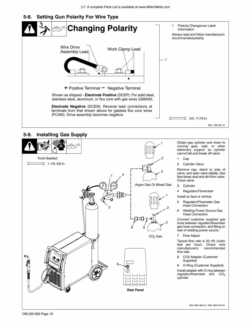
5-8. Setting Gun Polarity For Wire Type
1 Polarity Changeover LabelInformation
Always read and follow manufacture’srecommended polarity.
1
3/4, 11/16 in.
Ref. 190 821-A
Changing Polarity
�
�
Wire DriveAssembly Lead
Work Clamp Lead
� Positive Terminal
Shown as shipped − Electrode Positive (DCEP): For solid steel,stainless steel, aluminum, or flux core with gas wires (GMAW).
� Negative Terminal
Electrode Negative (DCEN): Reverse lead connections atterminals from that shown above for gasless flux core wires(FCAW). Drive assembly becomes negative.
5-9. Installing Gas Supply
Ref. 804 654-A / Ref. 804 912-A
Tools Needed:
Obtain gas cylinder and chain torunning gear, wall, or otherstationary support so cylindercannot fall and break off valve.
1 Cap
2 Cylinder Valve
Remove cap, stand to side ofvalve, and open valve slightly. Gasflow blows dust and dirt from valve.Close valve.
3 Cylinder
4 Regulator/Flowmeter
Install so face is vertical.
5 Regulator/Flowmeter GasHose Connection
6 Welding Power Source GasHose Connection
Connect customer supplied gashose between regulator/flowmetergas hose connection, and fitting onrear of welding power source.
7 Flow Adjust
Typical flow rate is 20 cfh (cubicfeet per hour). Check wiremanufacturer’s recommendedflow rate.
8 CO2 Adapter (CustomerSupplied)
9 O-Ring (Customer Supplied)
Install adapter with O-ring betweenregulator/flowmeter and CO2cylinder.
1-1/8, 5/8 in.
1
2
37
Rear Panel
6
4
5
1
2
3
8 9
Argon Gas Or Mixed Gas
CO2 Gas
� A complete Parts List is available at www.MillerWelds.com
OM-230 693 Page 19
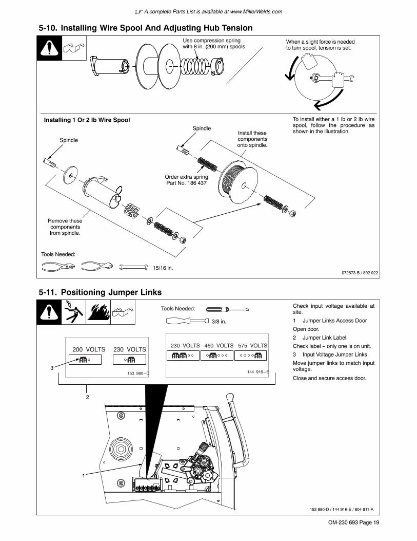
5-10. Installing Wire Spool And Adjusting Hub Tension
When a slight force is neededto turn spool, tension is set.
15/16 in.
Use compression springwith 8 in. (200 mm) spools.
Tools Needed:
072573-B / 802 922
Installing 1 Or 2 lb Wire Spool To install either a 1 lb or 2 lb wirespool, follow the procedure asshown in the illustration.
Remove thesecomponentsfrom spindle.
Spindle
SpindleInstall thesecomponentsonto spindle.
Order extra springPart No. 186 437
5-11. Positioning Jumper Links
Tools Needed:
3/8 in.
Check input voltage available atsite.
1 Jumper Links Access Door
Open door.
2 Jumper Link Label
Check label − only one is on unit.
3 Input Voltage Jumper Links
Move jumper links to match inputvoltage.
Close and secure access door.
153 980-D / 144 916-E / 804 911-A
2
200�VOLTS 230�VOLTS
153�980-D
230�VOLTS 460�VOLTS 575�VOLTS
144�916-E3
1

� A complete Parts List is available at www.MillerWelds.com
OM-230 693 Page 20
5-12. Electrical Service Guide
Failure to follow these electrical service guide recommendations could create an electric shock or fire hazard. These recommenda-tions are for a dedicated branch circuit sized for the rated output and duty cycle of the welding power source.
60 Hz Single Phase
Input Voltage (V) 200 230 400 460 575
Input Amperes (A) At Rated Output 48 46 24 23 18
Max Recommended Standard Fuse Rating In Amperes 1
Time-Delay Fuses 2 60 50 30 25 20
Normal Operating Fuses 3 70 60 35 30 25
Min Input Conductor Size In AWG 4 8 8 12 12 14
Max Recommended Input Conductor Length In Feet (Meters)96
(29)127(39)
156(47)
206(63)
209(64)
Min Grounding Conductor Size In AWG 4 8 10 12 12 14
Elec Serv 2011−04
Reference: 2011 National Electrical Code (NEC) (including article 630)
1 If a circuit breaker is used in place of a fuse, choose a circuit breaker with time-current curves comparable to the recommended fuse.2 “Time-Delay” fuses are UL class “RK5” . See UL 248.3 “Normal Operating” (general purpose - no intentional delay) fuses are UL class “K5” (up to and including 60 amp), and UL class “H” ( 65 amp and
above).4 Conductor data in this section specifies conductor size (excluding flexible cord or cable) between the panelboard and the equipment per NEC Table
310.15(B)(16). If a flexible cord or cable is used, minimum conductor size may increase. See NEC Table 400.5(A) for flexible cord and cablerequirements.
� A complete Parts List is available at www.MillerWelds.com
OM-230 693 Page 21
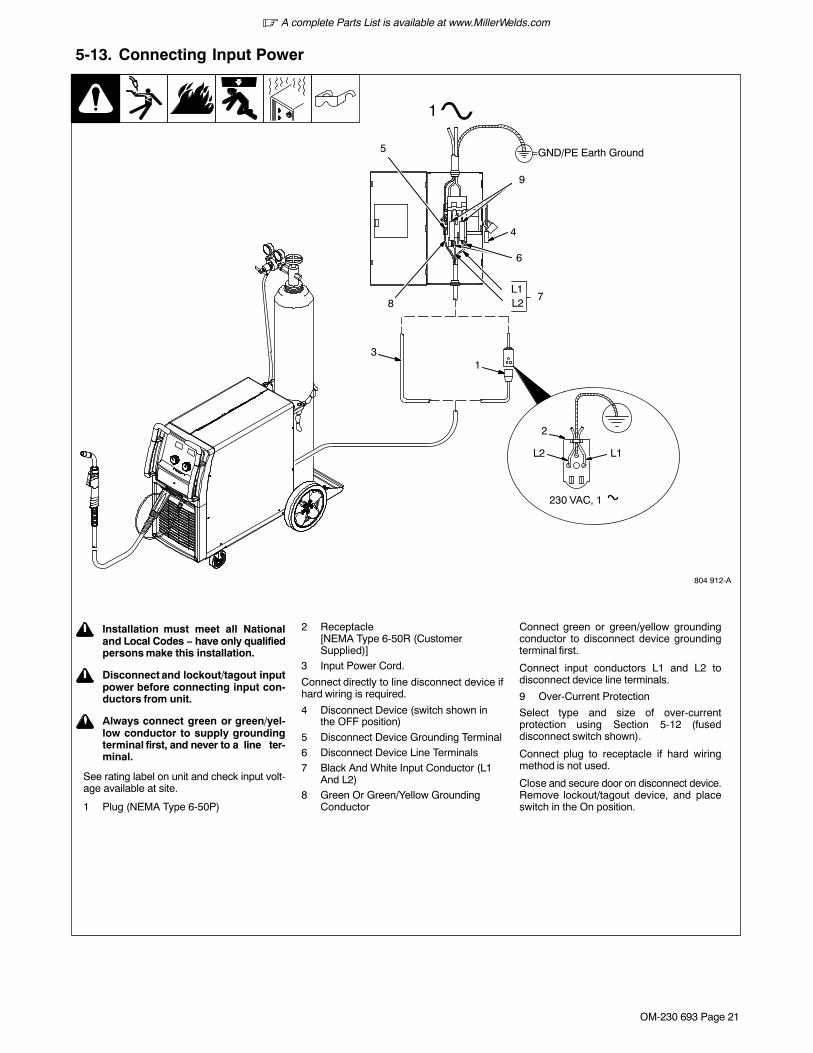
5-13. Connecting Input Power
804 912-A
L1L2
230 VAC, 1
2
! Installation must meet all Nationaland Local Codes − have only qualifiedpersons make this installation.
! Disconnect and lockout/tagout inputpower before connecting input con-ductors from unit.
! Always connect green or green/yel-low conductor to supply groundingterminal first, and never to a line ter-minal.
See rating label on unit and check input volt-age available at site.
1 Plug (NEMA Type 6-50P)
2 Receptacle[NEMA Type 6-50R (CustomerSupplied)]
3 Input Power Cord.
Connect directly to line disconnect device ifhard wiring is required.
4 Disconnect Device (switch shown inthe OFF position)
5 Disconnect Device Grounding Terminal6 Disconnect Device Line Terminals7 Black And White Input Conductor (L1
And L2)8 Green Or Green/Yellow Grounding
Conductor
Connect green or green/yellow groundingconductor to disconnect device groundingterminal first.
Connect input conductors L1 and L2 todisconnect device line terminals.
9 Over-Current Protection
Select type and size of over-currentprotection using Section 5-12 (fuseddisconnect switch shown).
Connect plug to receptacle if hard wiringmethod is not used.
Close and secure door on disconnect device.Remove lockout/tagout device, and placeswitch in the On position.
13
1
=GND/PE Earth Ground
4
L1L28
7
5
6
9
� A complete Parts List is available at www.MillerWelds.com
OM-230 693 Page 22
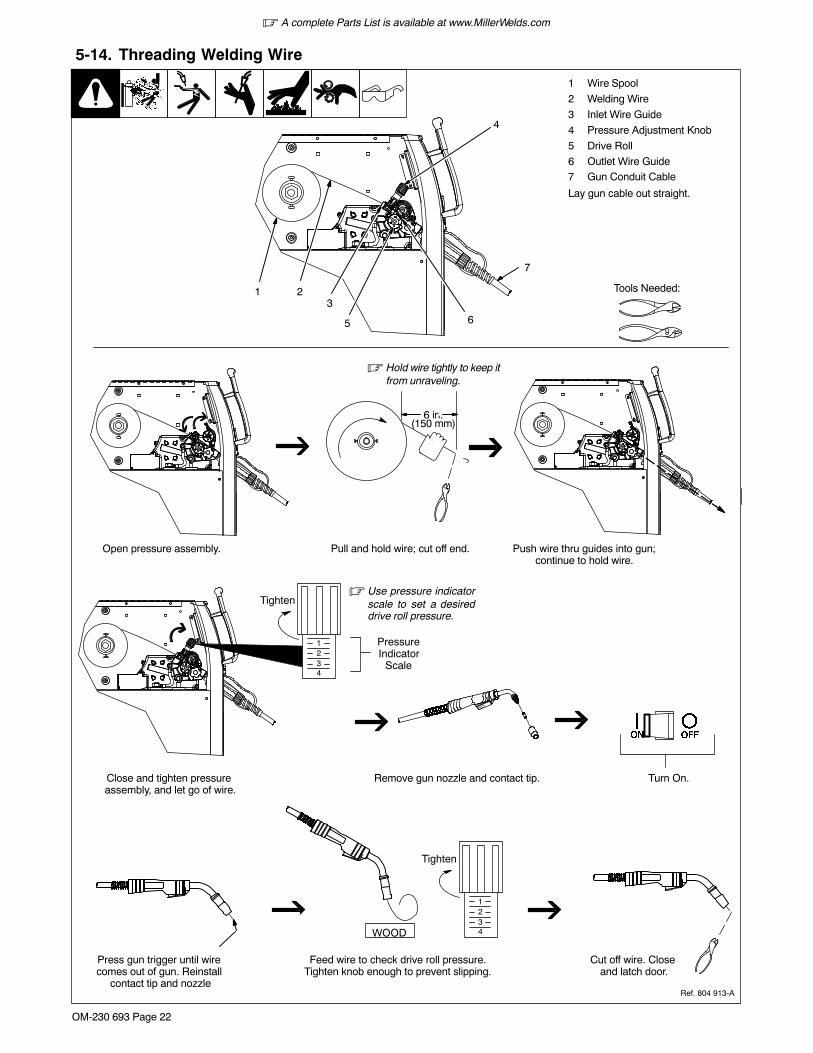
5-14. Threading Welding Wire
1 Wire Spool
2 Welding Wire
3 Inlet Wire Guide
4 Pressure Adjustment Knob
5 Drive Roll
6 Outlet Wire Guide7 Gun Conduit Cable
Lay gun cable out straight.
Tools Needed:
6 in.(150 mm)
� Hold wire tightly to keep itfrom unraveling.
WOOD
Open pressure assembly. Pull and hold wire; cut off end. Push wire thru guides into gun;continue to hold wire.
Close and tighten pressure assembly, and let go of wire.
Remove gun nozzle and contact tip. Turn On.
Press gun trigger until wire comes out of gun. Reinstall
contact tip and nozzle
Feed wire to check drive roll pressure.Tighten knob enough to prevent slipping.
Cut off wire. Close and latch door.
Ref. 804 913-A
Tighten
1234
� Use pressure indicatorscale to set a desireddrive roll pressure.
PressureIndicator
Scale
Tighten
1234
4
7
5 6
213

� A complete Parts List is available at www.MillerWelds.com
OM-230 693 Page 23
Notes
� A complete Parts List is available at www.MillerWelds.com
OM-230 693 Page 24
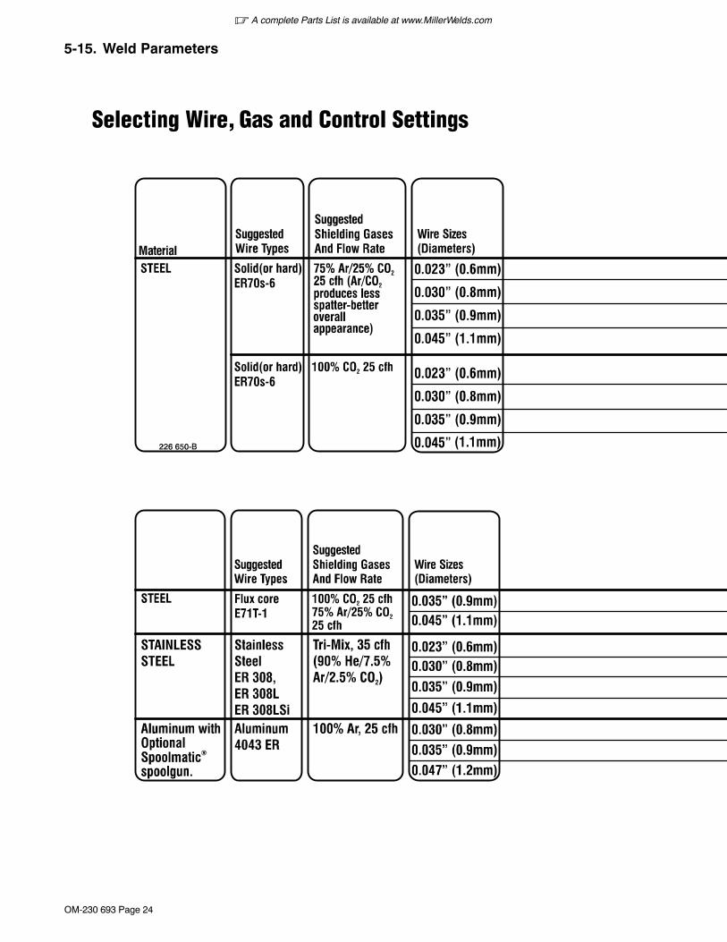
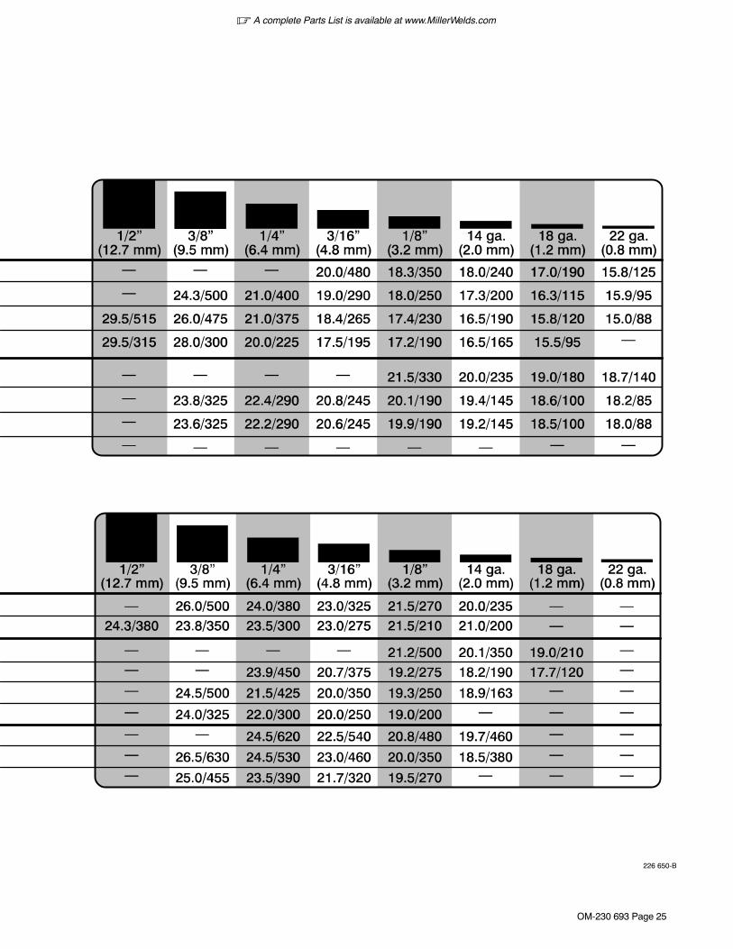
5-15. Weld Parameters
� A complete Parts List is available at www.MillerWelds.com
OM-230 693 Page 25
226 650-B
� A complete Parts List is available at www.MillerWelds.com
OM-230 693 Page 26
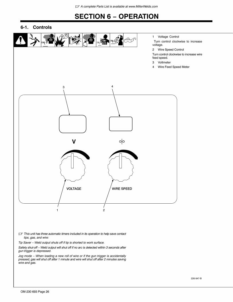
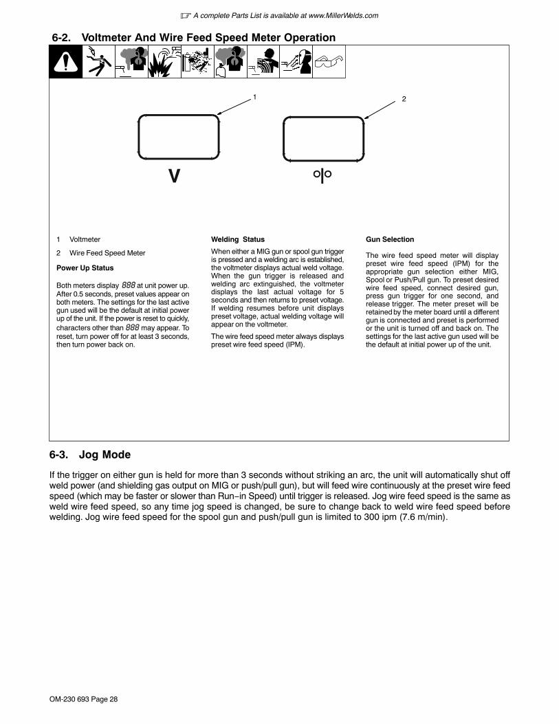
SECTION 6 − OPERATION6-1. Controls
226 647-B
1 Voltage Control
Turn control clockwise to increasevoltage.
2 Wire Speed Control
Turn control clockwise to increase wirefeed speed.
3 Voltmeter
4 Wire Feed Speed Meter
2
3
� This unit has three automatic timers included in its operation to help save contacttips, gas, and wire:
Tip Saver − Weld output shuts off if tip is shorted to work surface.
Safety shut-off − Weld output will shut off if no arc is detected within 3 seconds aftergun trigger is depressed.
Jog mode − When loading a new roll of wire or if the gun trigger is accidentallypressed, gas will shut off after 1 minute and wire will shut off after 2 minutes savingwire and gas.
1
4

� A complete Parts List is available at www.MillerWelds.com
OM-230 693 Page 27
JOG Mode
If the trigger on either gun is held for morethan 3 seconds without striking an arc, theunit will automatically shut off weld power(and shielding gas output on MIG gunonly), but will feed wire continuously at thepreset wire feed speed (which may befaster or slower than Run−in Speed) untiltrigger is released.
Run−in Wire Feed Speed Settings
Run−in settings for the MIG and SpoolGuns are independently set and stored inunit memory. The settings are in percent ofthe welding wire feed speed preset. Bothsettings are adjustable from 25 to 150percent.
MIG Gun Run−in is factory set at 100%which is recommended for most wire sizesand types.Spool Gun Run−in is factory set at 50%which is recommended for .030 & .035wire. A Run−in setting of 25% isrecommended for .047 wire.To check Run−in settings, start with thepower switch OFF. Press and hold the MIGor Spool Gun Trigger while turning thepower switch ON. The unit will power upwith both the displays reading 888 , thenthe voltage display will read run and thewire feed display will read the presetRun−in percentage from memory for thegun selected. To return to the weld modewithout making a change, simply releasetrigger and pull the trigger againmomentarily (one second).
To change Run−in settings, start with thepower switch OFF. Press and hold the MIGor Spool Gun Trigger while turning thepower switch ON. The unit will power upwith both the displays reading 888 , thenthe voltage display will read run and thewire feed display will read the presetRun−in percentage from memory for thegun selected. To change the Run−in value,release the trigger and turn the wire feedcontrol knob (or the wire feed adjustmentknob located on the bottom handle of thespool gun) to the desired setting for theselected gun. To return to weld mode afterthe Run−in speed change, pull the triggermomentarily (one second).
� A complete Parts List is available at www.MillerWelds.com
OM-230 693 Page 28
6-2. Voltmeter And Wire Feed Speed Meter Operation
1 Voltmeter
2 Wire Feed Speed Meter
Power Up Status
Both meters display 888 at unit power up.After 0.5 seconds, preset values appear onboth meters. The settings for the last activegun used will be the default at initial powerup of the unit. If the power is reset to quickly,characters other than 888 may appear. Toreset, turn power off for at least 3 seconds,then turn power back on.
Welding Status
When either a MIG gun or spool gun triggeris pressed and a welding arc is established,the voltmeter displays actual weld voltage.When the gun trigger is released andwelding arc extinguished, the voltmeterdisplays the last actual voltage for 5seconds and then returns to preset voltage.If welding resumes before unit displayspreset voltage, actual welding voltage willappear on the voltmeter.
The wire feed speed meter always displayspreset wire feed speed (IPM).
Gun Selection
The wire feed speed meter will displaypreset wire feed speed (IPM) for theappropriate gun selection either MIG,Spool or Push/Pull gun. To preset desiredwire feed speed, connect desired gun,press gun trigger for one second, andrelease trigger. The meter preset will beretained by the meter board until a differentgun is connected and preset is performedor the unit is turned off and back on. Thesettings for the last active gun used will bethe default at initial power up of the unit.
1 2
6-3. Jog Mode
If the trigger on either gun is held for more than 3 seconds without striking an arc, the unit will automatically shut offweld power (and shielding gas output on MIG or push/pull gun), but will feed wire continuously at the preset wire feedspeed (which may be faster or slower than Run−in Speed) until trigger is released. Jog wire feed speed is the same asweld wire feed speed, so any time jog speed is changed, be sure to change back to weld wire feed speed beforewelding. Jog wire feed speed for the spool gun and push/pull gun is limited to 300 ipm (7.6 m/min).
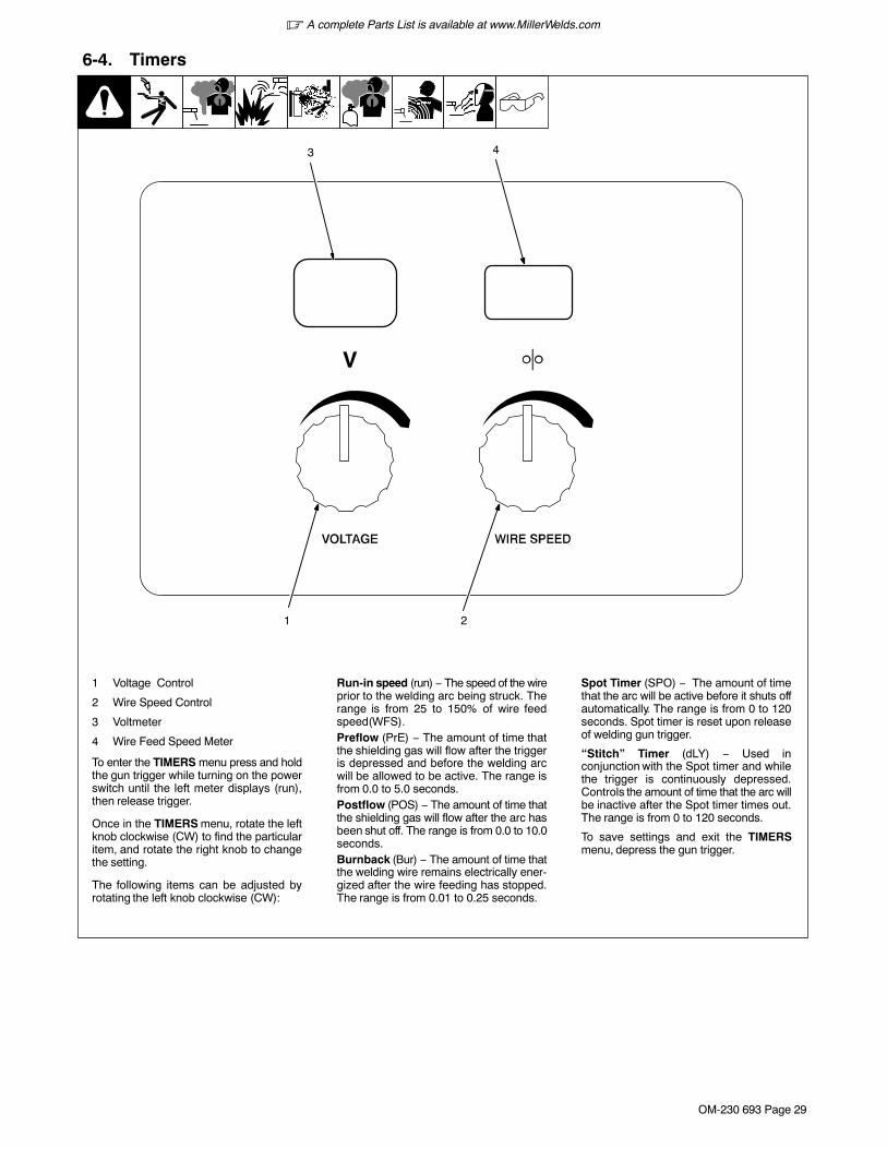
� A complete Parts List is available at www.MillerWelds.com
OM-230 693 Page 29
6-4. Timers
1 Voltage Control
2 Wire Speed Control
3 Voltmeter
4 Wire Feed Speed Meter
To enter the TIMERS menu press and holdthe gun trigger while turning on the powerswitch until the left meter displays (run),then release trigger.
Once in the TIMERS menu, rotate the leftknob clockwise (CW) to find the particularitem, and rotate the right knob to changethe setting.
The following items can be adjusted byrotating the left knob clockwise (CW):
Run-in speed (run) − The speed of the wireprior to the welding arc being struck. Therange is from 25 to 150% of wire feedspeed(WFS).Preflow (PrE) − The amount of time thatthe shielding gas will flow after the triggeris depressed and before the welding arcwill be allowed to be active. The range isfrom 0.0 to 5.0 seconds.Postflow (POS) − The amount of time thatthe shielding gas will flow after the arc hasbeen shut off. The range is from 0.0 to 10.0seconds.Burnback (Bur) − The amount of time thatthe welding wire remains electrically ener-gized after the wire feeding has stopped.The range is from 0.01 to 0.25 seconds.
Spot Timer (SPO) − The amount of timethat the arc will be active before it shuts offautomatically. The range is from 0 to 120seconds. Spot timer is reset upon releaseof welding gun trigger.
“Stitch” Timer (dLY) − Used inconjunction with the Spot timer and whilethe trigger is continuously depressed.Controls the amount of time that the arc willbe inactive after the Spot timer times out.The range is from 0 to 120 seconds.
To save settings and exit the TIMERSmenu, depress the gun trigger.
2
3
1
4
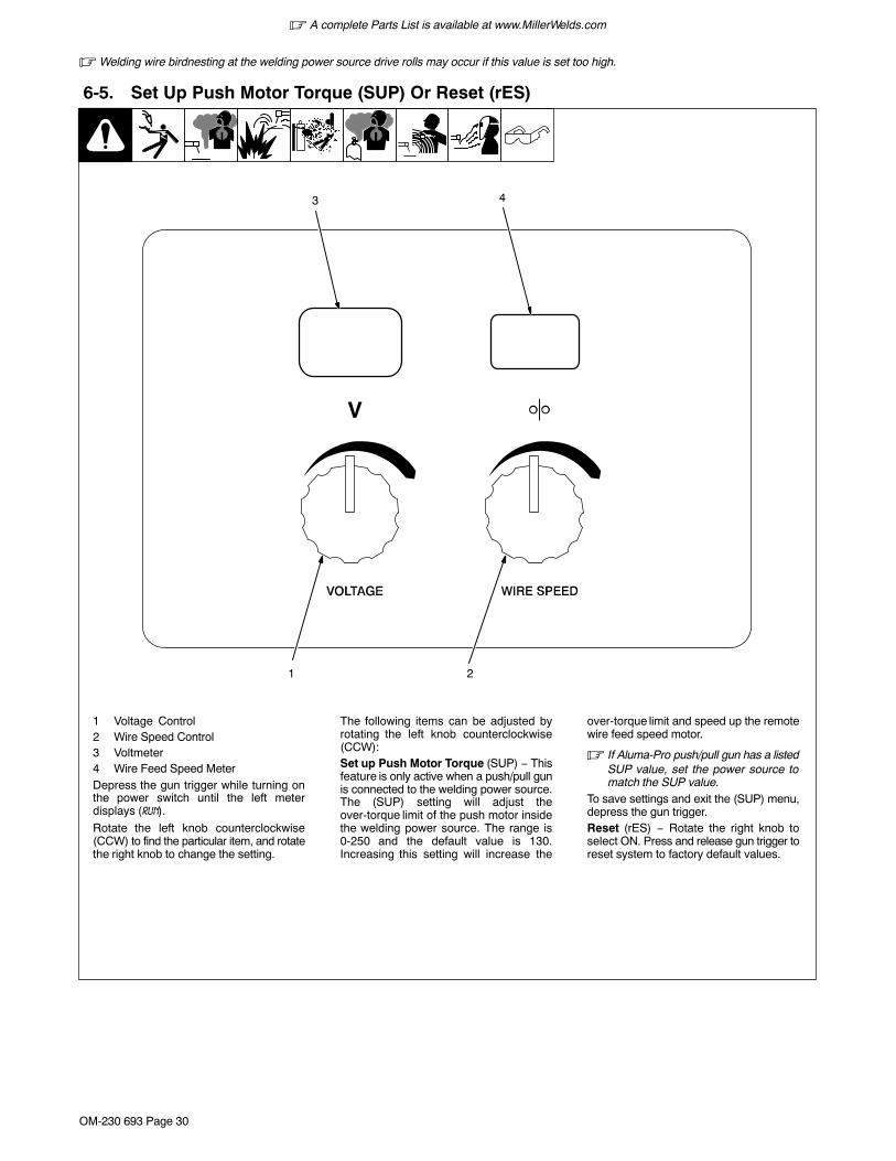
� A complete Parts List is available at www.MillerWelds.com
OM-230 693 Page 30
� Welding wire birdnesting at the welding power source drive rolls may occur if this value is set too high.
6-5. Set Up Push Motor Torque (SUP) Or Reset (rES)
1 Voltage Control2 Wire Speed Control3 Voltmeter4 Wire Feed Speed MeterDepress the gun trigger while turning onthe power switch until the left meterdisplays (run).
Rotate the left knob counterclockwise(CCW) to find the particular item, and rotatethe right knob to change the setting.
The following items can be adjusted byrotating the left knob counterclockwise(CCW):Set up Push Motor Torque (SUP) − Thisfeature is only active when a push/pull gunis connected to the welding power source.The (SUP) setting will adjust theover-torque limit of the push motor insidethe welding power source. The range is0-250 and the default value is 130.Increasing this setting will increase the
over-torque limit and speed up the remotewire feed speed motor.
� If Aluma-Pro push/pull gun has a listedSUP value, set the power source tomatch the SUP value.
To save settings and exit the (SUP) menu,depress the gun trigger.Reset (rES) − Rotate the right knob toselect ON. Press and release gun trigger toreset system to factory default values.
2
3
1
4
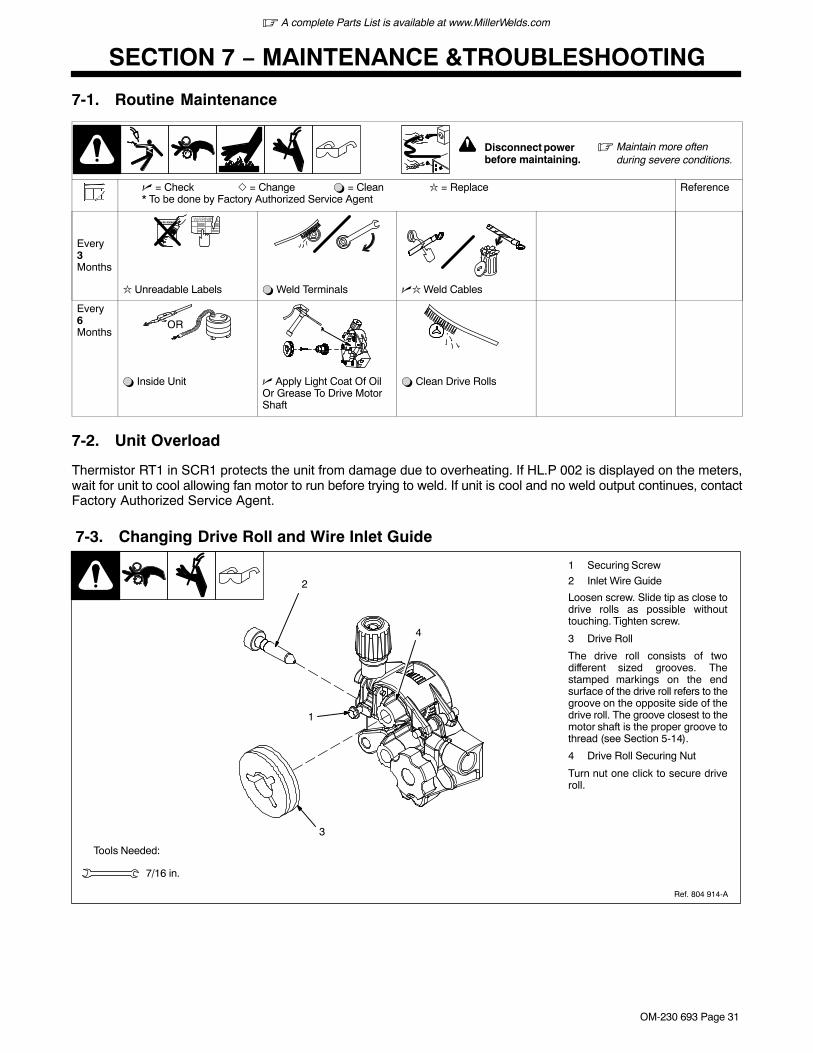
� A complete Parts List is available at www.MillerWelds.com
OM-230 693 Page 31
SECTION 7 − MAINTENANCE &TROUBLESHOOTING
7-1. Routine Maintenance
! Disconnect power before maintaining.
� Maintain more oftenduring severe conditions.
� = Check � = Change � = Clean � = Replace* To be done by Factory Authorized Service Agent
Reference
Every3Months
� Unreadable Labels � Weld Terminals �� Weld Cables
Every6Months
OR
� Inside Unit � Apply Light Coat Of OilOr Grease To Drive MotorShaft
� Clean Drive Rolls
7-2. Unit Overload
Thermistor RT1 in SCR1 protects the unit from damage due to overheating. If HL.P 002 is displayed on the meters,wait for unit to cool allowing fan motor to run before trying to weld. If unit is cool and no weld output continues, contactFactory Authorized Service Agent.
7-3. Changing Drive Roll and Wire Inlet Guide
1 Securing Screw
2 Inlet Wire Guide
Loosen screw. Slide tip as close todrive rolls as possible withouttouching. Tighten screw.
3 Drive Roll
The drive roll consists of twodifferent sized grooves. Thestamped markings on the endsurface of the drive roll refers to thegroove on the opposite side of thedrive roll. The groove closest to themotor shaft is the proper groove tothread (see Section 5-14).
4 Drive Roll Securing Nut
Turn nut one click to secure driveroll.
Tools Needed:
7/16 in.
1
2
3
4
Ref. 804 914-A
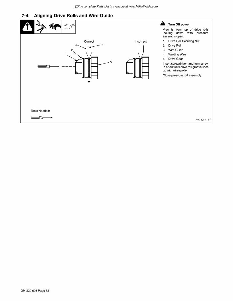
� A complete Parts List is available at www.MillerWelds.com
OM-230 693 Page 32
7-4. Aligning Drive Rolls and Wire Guide
! Turn Off power.
View is from top of drive rollslooking down with pressureassembly open.
1 Drive Roll Securing Nut
2 Drive Roll
3 Wire Guide
4 Welding Wire5 Drive Gear
Insert screwdriver, and turn screwin or out until drive roll groove linesup with wire guide.
Close pressure roll assembly.
Ref. 800 412-A
Correct Incorrect43
21
5
Tools Needed:

� A complete Parts List is available at www.MillerWelds.com
OM-230 693 Page 33
7-5. Troubleshooting
Trouble Remedy
No weld output; wire does not feed. Be sure line disconnect switch is On (see Section 5-13).
Replace building line fuse or reset circuit breaker if open (see Section 5-13).
Secure gun trigger connections (see welding gun Owner’s Manual).
HL.P 001 appears on meters. Turn power switch off and back on, if HL.P 001 appears on meters again,have Factory Authorized Service Agent check unit.
HL.P 002 appears on meters. Thermistor RT1 is detecting an overheating condition. Wait for unit to coolallowing the fan to run. After unit is cool, if HL.P 002 message remains, have Factory Authorized ServiceAgent check for an open Thermistor RT1 (see Section 7-2).
HL.P 004 appears on meters. Reset message by releasing the trigger or removing stuck wire causingshort circuit (see Section 6-2) . If message remains, have Factory Authorized Service Agent check forshorted trigger leads.
Have Factory Authorized Service Agent check Power switch.
Have Factory Authorized Service Agent check all board connections and main control board.
No Weld Output; wire feeds. Connect work clamp to get good metal to metal contact.
Replace contact tip (see welding gun Owner’s Manual.
HL.P 003 appears on meters, have Factory Authorized Service Agent check main control board and mainrectifier.
Low weld output. Connect unit to proper input voltage or check for low line voltage (see Section 5-13).
Check input voltage jumper links and correct position if necessary (see Section 5-11).
Have Factory Authorized Service Agent check main control board.
Fan motor does not run. Have Factory Authorized Service Agent check fan-on-demand circuit.
Low, high, or erratic wire speed. Readjust front panel settings (see Section 6-1).
Change to correct size drive rolls (see Section 7-3).
Readjust drive roll pressure (see Section 5-14).
Replace inlet guide, contact tip, and/or liner if necessary (see welding gun Owner’s Manual).
Check position of input jumper links (see Section 5-11).
Have Factory Authorized Service Agent check main control board.

� A complete Parts List is available at www.MillerWelds.com
OM-230 693 Page 34
Trouble Remedy
No wire feed. Turn Wire Speed control to higher setting (see Section 6-1).
Clear obstruction in gun contact tip or liner (see welding gun Owner’s Manual).
Readjust drive roll pressure (see Section 5-14).
Change to correct size drive rolls (see Section 7-3).
Rethread welding wire (see Section 5-14).
HL.P 002 appears on meters. Thermistor T is detecting an overheating condition. Wait for unit to coolallowing the fan to run. After unit is cool, If HL.P 002 message remains, contact Factory AuthorizedService Agent (see Section 7-2).
HL.P 004 appears on meters. Reset message by releasing the trigger or removing stuck wire causingshort circuit (see Section 6-2) . If message remains, have Factory Authorized Service Agent check forshorted trigger leads.
HL.P 005 appears on meters. Wire feed malfunction. Check wire feed delivery system.
Check gun trigger and leads. Repair or replace gun if necessary.
Have Factory Authorized Service Agent check main control board.

� A complete Parts List is available at www.MillerWelds.com
OM-230 693 Page 35
Notes
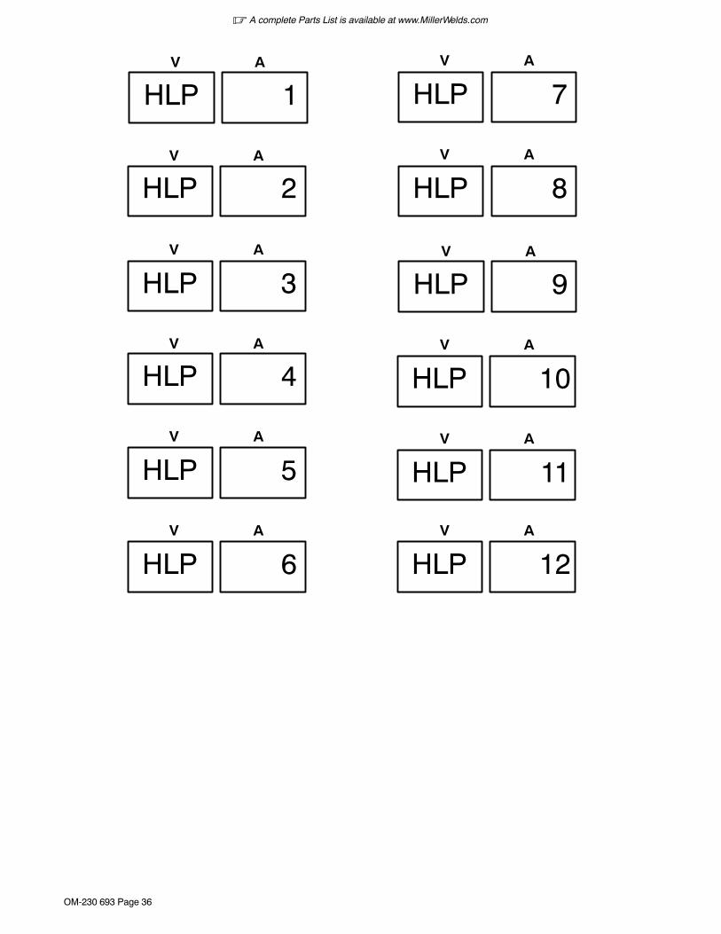
� A complete Parts List is available at www.MillerWelds.com
OM-230 693 Page 36
AV
AV
AV
HLP 1
AV
AV
AV
AV
AV
HLP 2
HLP 3
HLP 4
HLP 5
AV
HLP 6
AV
HLP 7
HLP 9
HLP 10
HLP 11
AV
HLP 8
AV
HLP 12
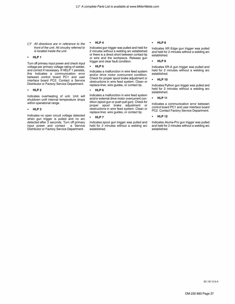
� A complete Parts List is available at www.MillerWelds.com
OM-230 693 Page 37
SC-187 212-A
� All directions are in reference to thefront of the unit. All circuitry referred tois located inside the unit.
� HLP 1
Turn off primary input power and check inputvoltage per primary voltage rating of welder,and correct if necessary. If HELP 1 persists,this Indicates a communication errorbetween control board PC1 and userinterface board PC2. Contact a ServiceDistributor or Factory Service Department.
� HLP 2
Indicates overheating of unit. Unit willshutdown until internal temperature dropswithin operational range.
� HLP 3
Indicates no open circuit voltage detectedwhen gun trigger is pulled and no arcdetected after 3 seconds. Turn off primaryinput power and contact a ServiceDistributor or Factory Service Department.
� HLP 4
Indicates gun trigger was pulled and held for2 minutes without a welding arc establishedor there is a direct short between contact tipor wire and the workpiece. Release guntrigger and clear fault condition.
� HLP 5
Indicates a malfunction in wire feed systemand/or drive motor overcurrent condition.Check for proper spool brake adjustment orobstructions in wire feed system. Clean orreplace liner, wire guides, or contact tip.
� HLP 6
Indicates a malfunction in wire feed systemand/or external drive motor overcurrent con-dition (spool gun or push-pull gun). Check forproper spool brake adjustment orobstructions in wire feed system. Clean orreplace liner, wire guides, or contact tip.
� HLP 7
Indicates spool gun trigger was pulled andheld for 2 minutes without a welding arcestablished.
� HLP 8
Indicates XR Edge gun trigger was pulledand held for 2 minutes without a welding arcestablished.
� HLP 9
Indicates XR-A gun trigger was pulled andheld for 2 minutes without a welding arcestablished.
� HLP 10
Indicates Python gun trigger was pulled andheld for 2 minutes without a welding arcestablished.
� HLP 11
Indicates a communication error betweencontrol board PC1 and user interface boardPC2. Contact Factory Service Department.
� HLP 12
Indicates Aluma-Pro gun trigger was pulledand held for 2 minutes without a welding arcestablished.
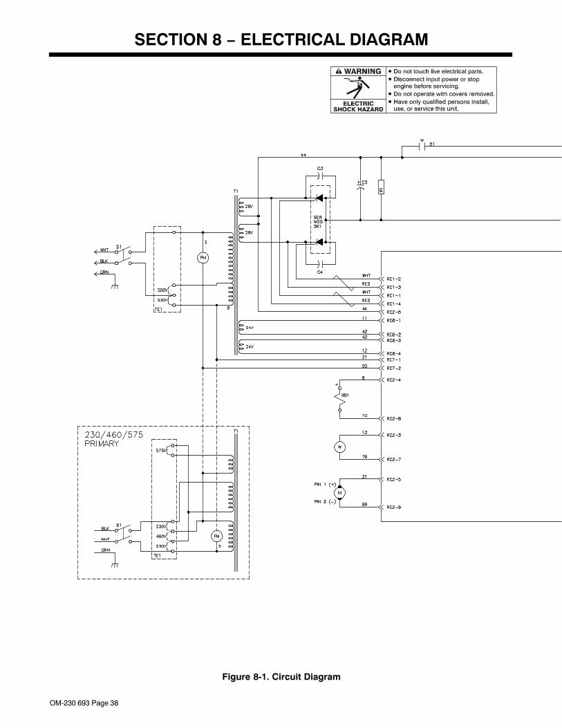
OM-230 693 Page 38
SECTION 8 − ELECTRICAL DIAGRAM
Figure 8-1. Circuit Diagram
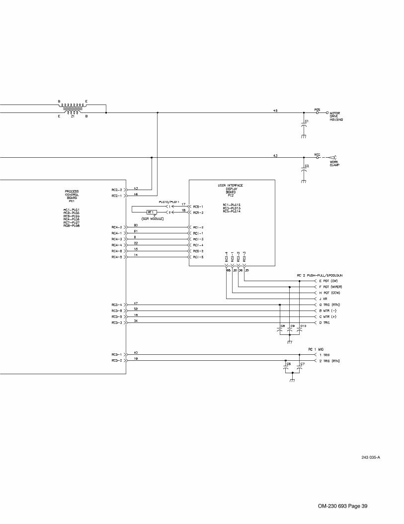
OM-230 693 Page 39
243 035-A
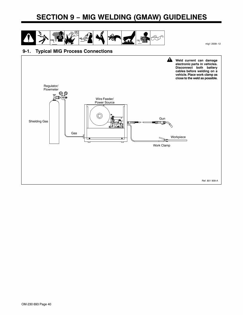
OM-230 693 Page 40
SECTION 9 − MIG WELDING (GMAW) GUIDELINES
mig1 2009−12
Wire Feeder/Power Source
Workpiece
Gun
Regulator/Flowmeter
Gas
Shielding Gas
Work Clamp
9-1. Typical MIG Process Connections
! Weld current can damageelectronic parts in vehicles.Disconnect both batterycables before welding on avehicle. Place work clamp asclose to the weld as possible.
Ref. 801 909-A
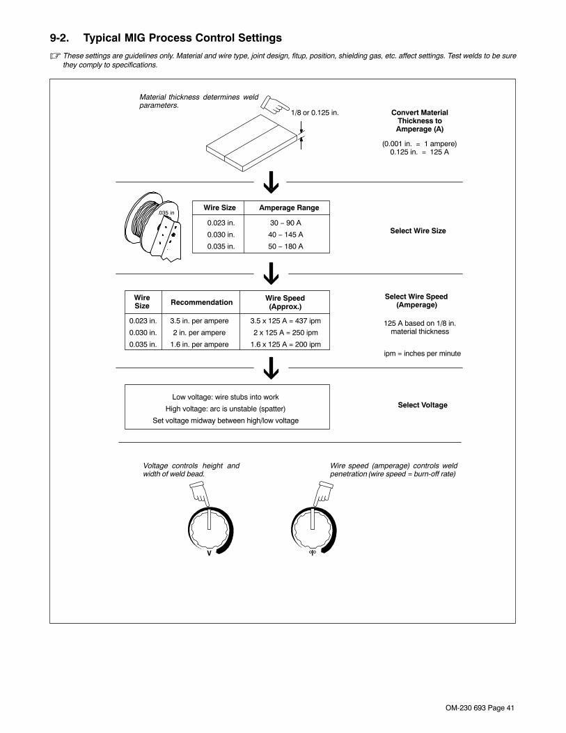
OM-230 693 Page 41
9-2. Typical MIG Process Control Settings
� These settings are guidelines only. Material and wire type, joint design, fitup, position, shielding gas, etc. affect settings. Test welds to be surethey comply to specifications.
3.5 x 125 A = 437 ipm
2 x 125 A = 250 ipm
1.6 x 125 A = 200 ipm
30 − 90 A
40 − 145 A
50 − 180 A
Convert MaterialThickness toAmperage (A)
Material thickness determines weldparameters.
.035 in
Recommendation Wire Speed(Approx.)
1/8 or 0.125 in.
(0.001 in. = 1 ampere)0.125 in. = 125 A
Wire Size Amperage Range
0.023 in.
0.030 in.
0.035 in.
Select Wire Size
WireSize
0.023 in.
0.030 in.
0.035 in.
3.5 in. per ampere
2 in. per ampere
1.6 in. per ampere
Select Wire Speed(Amperage)
125 A based on 1/8 in.material thickness
ipm = inches per minute
Low voltage: wire stubs into work
High voltage: arc is unstable (spatter)
Set voltage midway between high/low voltage
Select Voltage
Voltage controls height andwidth of weld bead.
Wire speed (amperage) controls weldpenetration (wire speed = burn-off rate)
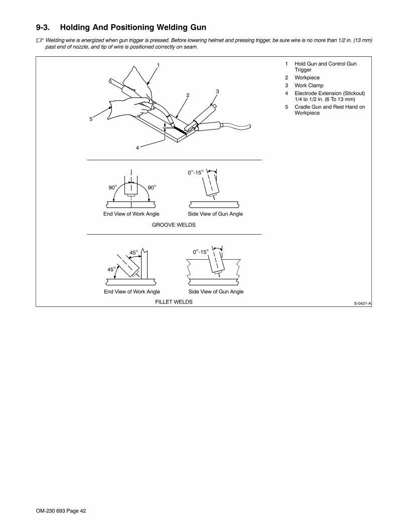
OM-230 693 Page 42
9-3. Holding And Positioning Welding Gun
� Welding wire is energized when gun trigger is pressed. Before lowering helmet and pressing trigger, be sure wire is no more than 1/2 in. (13 mm)past end of nozzle, and tip of wire is positioned correctly on seam.
1 Hold Gun and Control GunTrigger
2 Workpiece
3 Work Clamp
4 Electrode Extension (Stickout)1/4 to 1/2 in. (6 To 13 mm)
5 Cradle Gun and Rest Hand onWorkpiece
23
5
4
90° 90°
0°-15°
45°
45°
1
0°-15°
S-0421-A
End View of Work Angle Side View of Gun Angle
GROOVE WELDS
End View of Work Angle Side View of Gun Angle
FILLET WELDS
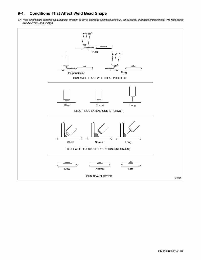
OM-230 693 Page 43
9-4. Conditions That Affect Weld Bead Shape
� Weld bead shape depends on gun angle, direction of travel, electrode extension (stickout), travel speed, thickness of base metal, wire feed speed(weld current), and voltage.
Slow
FILLET WELD ELECTODE EXTENSIONS (STICKOUT)
ELECTRODE EXTENSIONS (STICKOUT)
GUN ANGLES AND WELD BEAD PROFILES
10°
10°
GUN TRAVEL SPEEDS-0634
Push
Perpendicular Drag
Short Normal Long
Short Normal Long
Normal Fast
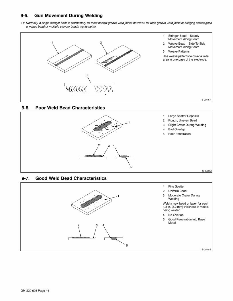
OM-230 693 Page 44
9-5. Gun Movement During Welding
� Normally, a single stringer bead is satisfactory for most narrow groove weld joints; however, for wide groove weld joints or bridging across gaps,a weave bead or multiple stringer beads works better.
1 Stringer Bead − SteadyMovement Along Seam
2 Weave Bead − Side To SideMovement Along Seam
3 Weave Patterns
Use weave patterns to cover a widearea in one pass of the electrode.
S-0054-A
3
1 2
9-6. Poor Weld Bead Characteristics
1 Large Spatter Deposits
2 Rough, Uneven Bead
3 Slight Crater During Welding
4 Bad Overlap
5 Poor Penetration
5
42 3
1
S-0053-A
9-7. Good Weld Bead Characteristics
1 Fine Spatter
2 Uniform Bead
3 Moderate Crater DuringWelding
Weld a new bead or layer for each1/8 in. (3.2 mm) thickness in metalsbeing welded.
4 No Overlap
5 Good Penetration into BaseMetal
S-0052-B
2 3
1
4
5
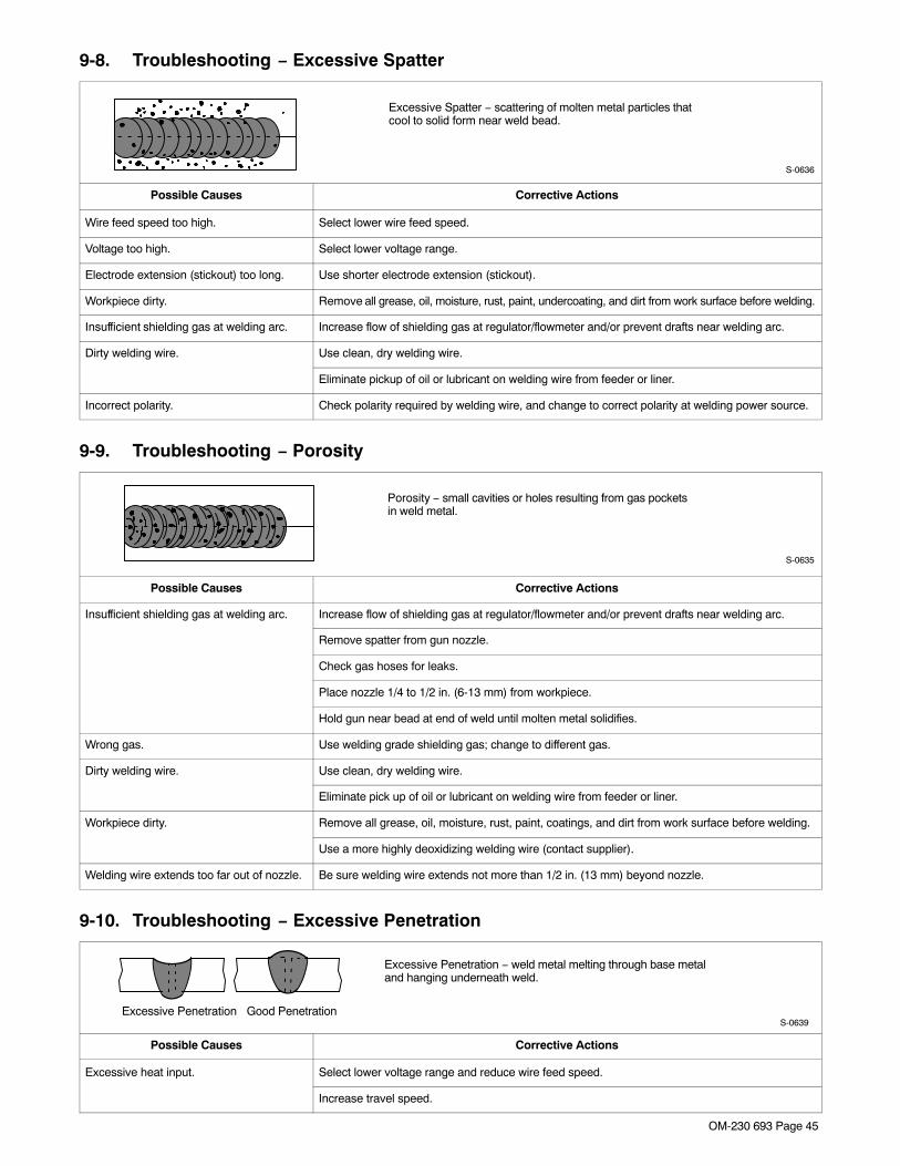
OM-230 693 Page 45
9-8. Troubleshooting − Excessive Spatter
Excessive Spatter − scattering of molten metal particles thatcool to solid form near weld bead.
S-0636
Possible Causes Corrective Actions
Wire feed speed too high. Select lower wire feed speed.
Voltage too high. Select lower voltage range.
Electrode extension (stickout) too long. Use shorter electrode extension (stickout).
Workpiece dirty. Remove all grease, oil, moisture, rust, paint, undercoating, and dirt from work surface before welding.
Insufficient shielding gas at welding arc. Increase flow of shielding gas at regulator/flowmeter and/or prevent drafts near welding arc.
Dirty welding wire. Use clean, dry welding wire.
Eliminate pickup of oil or lubricant on welding wire from feeder or liner.
Incorrect polarity. Check polarity required by welding wire, and change to correct polarity at welding power source.
9-9. Troubleshooting − Porosity
Porosity − small cavities or holes resulting from gas pocketsin weld metal.
S-0635
Possible Causes Corrective Actions
Insufficient shielding gas at welding arc. Increase flow of shielding gas at regulator/flowmeter and/or prevent drafts near welding arc.
Remove spatter from gun nozzle.
Check gas hoses for leaks.
Place nozzle 1/4 to 1/2 in. (6-13 mm) from workpiece.
Hold gun near bead at end of weld until molten metal solidifies.
Wrong gas. Use welding grade shielding gas; change to different gas.
Dirty welding wire. Use clean, dry welding wire.
Eliminate pick up of oil or lubricant on welding wire from feeder or liner.
Workpiece dirty. Remove all grease, oil, moisture, rust, paint, coatings, and dirt from work surface before welding.
Use a more highly deoxidizing welding wire (contact supplier).
Welding wire extends too far out of nozzle. Be sure welding wire extends not more than 1/2 in. (13 mm) beyond nozzle.
9-10. Troubleshooting − Excessive Penetration
Good Penetration
Excessive Penetration − weld metal melting through base metaland hanging underneath weld.
Excessive PenetrationS-0639
Possible Causes Corrective Actions
Excessive heat input. Select lower voltage range and reduce wire feed speed.
Increase travel speed.
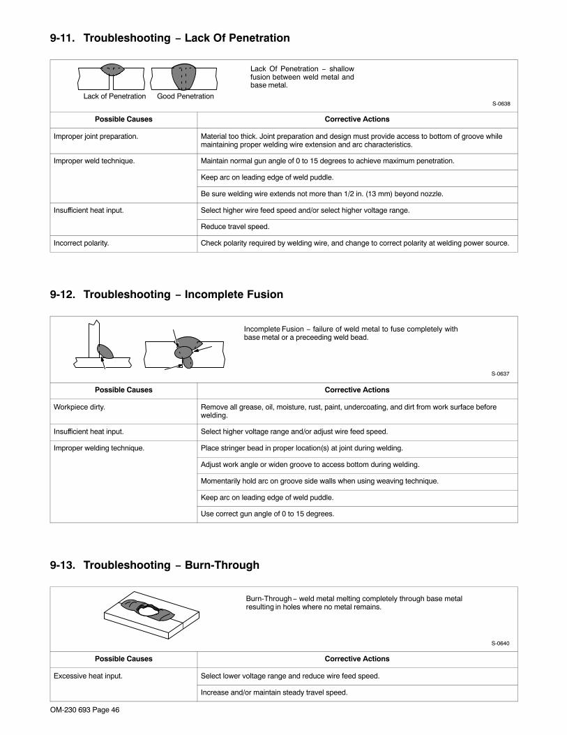
OM-230 693 Page 46
9-11. Troubleshooting − Lack Of Penetration
Lack Of Penetration − shallowfusion between weld metal andbase metal.
Lack of Penetration Good PenetrationS-0638
Possible Causes Corrective Actions
Improper joint preparation. Material too thick. Joint preparation and design must provide access to bottom of groove whilemaintaining proper welding wire extension and arc characteristics.
Improper weld technique. Maintain normal gun angle of 0 to 15 degrees to achieve maximum penetration.
Keep arc on leading edge of weld puddle.
Be sure welding wire extends not more than 1/2 in. (13 mm) beyond nozzle.
Insufficient heat input. Select higher wire feed speed and/or select higher voltage range.
Reduce travel speed.
Incorrect polarity. Check polarity required by welding wire, and change to correct polarity at welding power source.
9-12. Troubleshooting − Incomplete Fusion
Incomplete Fusion − failure of weld metal to fuse completely withbase metal or a preceeding weld bead.
S-0637
Possible Causes Corrective Actions
Workpiece dirty. Remove all grease, oil, moisture, rust, paint, undercoating, and dirt from work surface beforewelding.
Insufficient heat input. Select higher voltage range and/or adjust wire feed speed.
Improper welding technique. Place stringer bead in proper location(s) at joint during welding.
Adjust work angle or widen groove to access bottom during welding.
Momentarily hold arc on groove side walls when using weaving technique.
Keep arc on leading edge of weld puddle.
Use correct gun angle of 0 to 15 degrees.
9-13. Troubleshooting − Burn-Through
Burn-Through − weld metal melting completely through base metalresulting in holes where no metal remains.
S-0640
Possible Causes Corrective Actions
Excessive heat input. Select lower voltage range and reduce wire feed speed.
Increase and/or maintain steady travel speed.
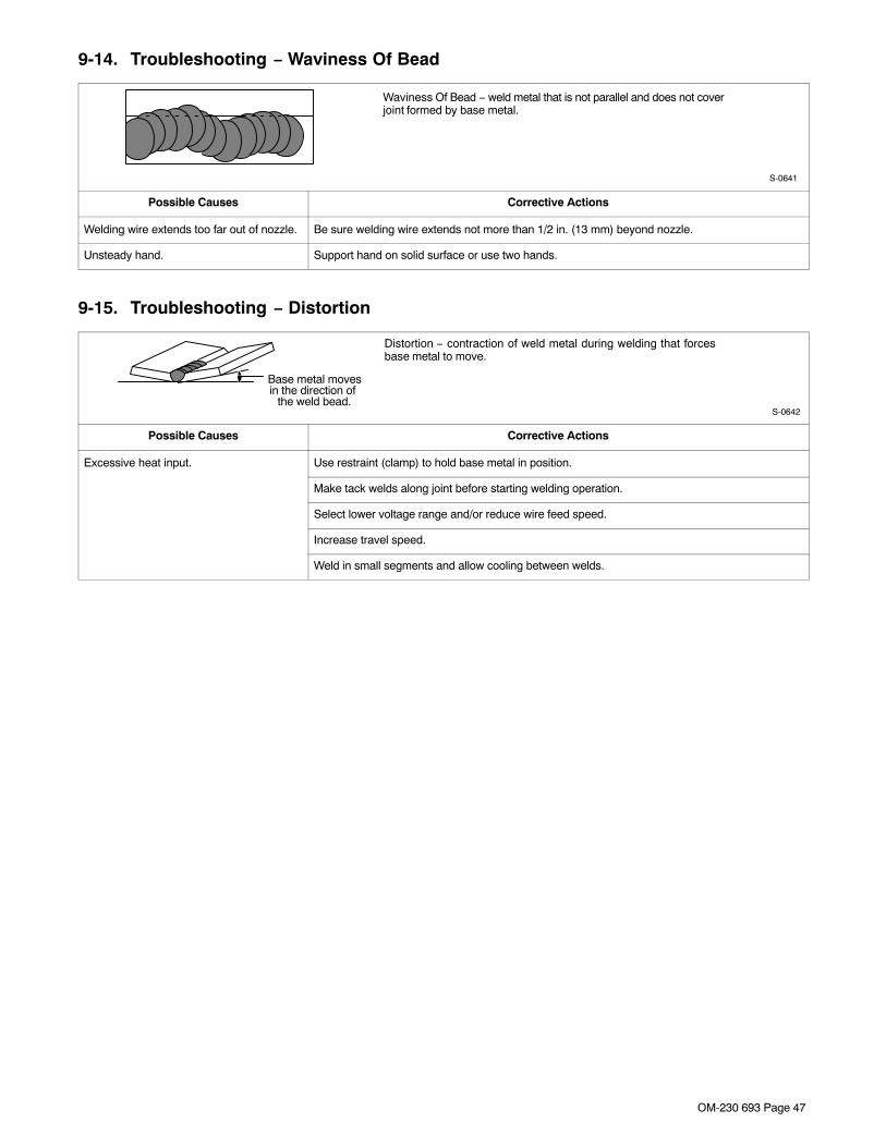
OM-230 693 Page 47
9-14. Troubleshooting − Waviness Of Bead
Waviness Of Bead − weld metal that is not parallel and does not coverjoint formed by base metal.
S-0641
Possible Causes Corrective Actions
Welding wire extends too far out of nozzle. Be sure welding wire extends not more than 1/2 in. (13 mm) beyond nozzle.
Unsteady hand. Support hand on solid surface or use two hands.
9-15. Troubleshooting − Distortion
Distortion − contraction of weld metal during welding that forcesbase metal to move.
Base metal movesin the direction of
the weld bead.S-0642
Possible Causes Corrective Actions
Excessive heat input. Use restraint (clamp) to hold base metal in position.
Make tack welds along joint before starting welding operation.
Select lower voltage range and/or reduce wire feed speed.
Increase travel speed.
Weld in small segments and allow cooling between welds.
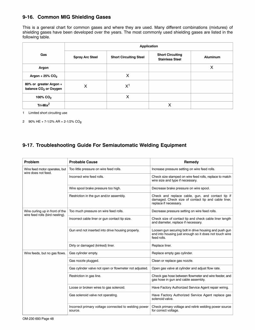
OM-230 693 Page 48
9-16. Common MIG Shielding Gases
This is a general chart for common gases and where they are used. Many different combinations (mixtures) ofshielding gases have been developed over the years. The most commonly used shielding gases are listed in thefollowing table.
Application
GasSpray Arc Steel Short Circuiting Steel
Short CircuitingStainless Steel
Aluminum
Argon X
Argon + 25% CO2 X
80% or greater Argon +balance CO2 or Oxygen
X X1
100% CO2 X
Tri-Mix2 X
1 Limited short circuiting use
2 90% HE + 7-1/2% AR + 2-1/2% CO2
9-17. Troubleshooting Guide For Semiautomatic Welding Equipment
Problem Probable Cause Remedy
Wire feed motor operates, butwire does not feed.
Too little pressure on wire feed rolls. Increase pressure setting on wire feed rolls.
Incorrect wire feed rolls. Check size stamped on wire feed rolls, replace to matchwire size and type if necessary.
Wire spool brake pressure too high. Decrease brake pressure on wire spool.
Restriction in the gun and/or assembly. Check and replace cable, gun, and contact tip ifdamaged. Check size of contact tip and cable liner,replace if necessary.
Wire curling up in front of thewire feed rolls (bird nesting).
Too much pressure on wire feed rolls. Decrease pressure setting on wire feed rolls.
Incorrect cable liner or gun contact tip size. Check size of contact tip and check cable liner lengthand diameter, replace if necessary.
Gun end not inserted into drive housing properly. Loosen gun securing bolt in drive housing and push gunend into housing just enough so it does not touch wirefeed rolls.
Dirty or damaged (kinked) liner. Replace liner.
Wire feeds, but no gas flows. Gas cylinder empty. Replace empty gas cylinder.
Gas nozzle plugged. Clean or replace gas nozzle.
Gas cylinder valve not open or flowmeter not adjusted. Open gas valve at cylinder and adjust flow rate.
Restriction in gas line. Check gas hose between flowmeter and wire feeder, andgas hose in gun and cable assembly.
Loose or broken wires to gas solenoid. Have Factory Authorized Service Agent repair wiring.
Gas solenoid valve not operating. Have Factory Authorized Service Agent replace gassolenoid valve.
Incorrect primary voltage connected to welding powersource.
Check primary voltage and relink welding power sourcefor correct voltage.

OM-230 693 Page 49
Problem RemedyProbable Cause
Welding arc not stable. Wire slipping in drive rolls. Adjust pressure setting on wire feed rolls. Replace worndrive rolls if necessary.
Wrong size gun liner or contact tip. Match liner and contact tip to wire size and type.
Incorrect voltage setting for selected wire feed speed onwelding power source.
Readjust welding parameters.
Loose connections at the gun weld cable or work cable. Check and tighten all connections.
Gun in poor shape or loose connection inside gun. Repair or replace gun as necessary.

OM-230 693 Page 50
SECTION 10 − PARTS LIST
10-1. Drive Roll And Wire Guide Kits
�Base selection of drive rolls upon the following recommended usages:
1 V-Grooved rolls for hard wire.
2 U-Grooved rolls for soft and soft shelled cored wires.
3 U-Cogged rolls for extremely soft shelled wires (usually hard surfacing types).
4 V-Knurled rolls for hard shelled cored wires.5 Drive roll types may be mixed to suit particular requirements (example: V-Knurled roll in combination
with U-Grooved).
Ref. S-0026-B/7-91
Wire Diameter
Fraction Decimal Metric
.023/.025 in.
.030 in.
.035 in.
.045 in.
.023/.025 in.
.030 in.
.035 in.
.045 in.
0.6 mm
0.8 mm
0.9 mm
1.2 mm
Kit No.
087 131
079 594
079 595
079 596
Drive Roll
Part No. Type
087 130
053 695
053 700
053 697
V-Grooved
V-Grooved
V-Grooved
V-Grooved
Inlet
056 192
056 192
056 192
056 193
Wire Guide
.030/.035 in. .030/.035 in. 0.8/0.9 mm 204 579 203 526 V-Grooved 056 192
A complete Parts List is available on-line at www.MillerWelds.com
Warranty Questions?
Call1-800-4-A-MILLERfor your localMiller distributor.
miller_warr 2011−01
Your distributor also givesyou ...
ServiceYou always get the fast,reliable response youneed. Most replacementparts can be in yourhands in 24 hours.
SupportNeed fast answers to thetough welding questions?Contact your distributor.The expertise of thedistributor and Miller isthere to help you, everystep of the way.
Effective January 1, 2011(Equipment with a serial number preface of MB or newer)This limited warranty supersedes all previous Miller warranties and is exclusive with no other
guarantees or warranties expressed or implied.LIMITED WARRANTY − Subject to the terms and conditionsbelow, Miller Electric Mfg. Co., Appleton, Wisconsin, warrants to itsoriginal retail purchaser that new Miller equipment sold after theeffective date of this limited warranty is free of defects in materialand workmanship at the time it is shipped by Miller. THISWARRANTY IS EXPRESSLY IN LIEU OF ALL OTHERWARRANTIES, EXPRESS OR IMPLIED, INCLUDING THEWARRANTIES OF MERCHANTABILITY AND FITNESS.
Within the warranty periods listed below, Miller will repair or replaceany warranted parts or components that fail due to such defects inmaterial or workmanship. Miller must be notified in writing withinthirty (30) days of such defect or failure, at which time Miller willprovide instructions on the warranty claim procedures to befollowed.
Miller shall honor warranty claims on warranted equipment listedbelow in the event of such a failure within the warranty timeperiods. All warranty time periods start on the delivery date of theequipment to the original end-user purchaser, and not to exceedone year after the equipment is shipped to a North Americandistributor or eighteen months after the equipment is shipped to anInternational distributor.
1. 5 Years Parts — 3 Years Labor* Original main power rectifiers only to include SCRs,
diodes, and discrete rectifier modules2. 3 Years — Parts and Labor
* Engine Driven Welding Generators(NOTE: Engines are warranted separately by theengine manufacturer.)
* Inverter Power Sources (Unless Otherwise Stated)* Plasma Arc Cutting Power Sources* Process Controllers* Semi-Automatic and Automatic Wire Feeders* Smith 30 Series Flowgauge and Flowmeter
Regulators (No Labor)* Transformer/Rectifier Power Sources* Water Coolant Systems (Integrated)
3. 2 Years — Parts* Auto-Darkening Helmet Lenses (No Labor)
4. 1 Year — Parts and Labor Unless Specified* Automatic Motion Devices* CoolBelt and CoolBand Blower Unit (No Labor)* External Monitoring Equipment and Sensors* Field Options
(NOTE: Field options are covered for the remainingwarranty period of the product they are installed in, orfor a minimum of one year — whichever is greater.)
* Flowgauge and Flowmeter Regulators (No Labor)* RFCS Foot Controls (Except RFCS-RJ45)* Fume Extractors* HF Units* ICE Plasma Cutting Torches (No Labor)* Induction Heating Power Sources, Coolers, and
Electronic Controls/Recorders* Load Banks* Motor Driven Guns (w/exception of Spoolmate
Spoolguns)* PAPR Blower Unit (No Labor)* Positioners and Controllers* Racks* Running Gear/Trailers* Spot Welders* Subarc Wire Drive Assemblies* Water Coolant Systems (Non-Integrated)* Weldcraft-Branded TIG Torches (No Labor)* Wireless Remote Foot/Hand Controls and Receivers* Work Stations/Weld Tables (No Labor)
5. 6 Months — Parts* Batteries* Bernard Guns (No Labor)* Tregaskiss Guns (No Labor)
6. 90 Days — Parts* Accessory (Kits)* Canvas Covers* Induction Heating Coils and Blankets, Cables, and
Non-Electronic Controls* M-Guns* MIG Guns and Subarc (SAW) Guns* Remote Controls and RFCS-RJ45* Replacement Parts (No labor)* Roughneck Guns* Spoolmate Spoolguns
Miller’s True Blue® Limited Warranty shall not apply to:
1. Consumable components; such as contact tips,cutting nozzles, contactors, brushes, relays, workstation table tops and welding curtains, or parts thatfail due to normal wear. (Exception: brushes andrelays are covered on all engine-driven products.)
2. Items furnished by Miller, but manufactured by others,such as engines or trade accessories. These items arecovered by the manufacturer’s warranty, if any.
3. Equipment that has been modified by any party other thanMiller, or equipment that has been improperly installed,improperly operated or misused based upon industrystandards, or equipment which has not had reasonableand necessary maintenance, or equipment which hasbeen used for operation outside of the specifications forthe equipment.
MILLER PRODUCTS ARE INTENDED FOR PURCHASE ANDUSE BY COMMERCIAL/INDUSTRIAL USERS AND PERSONSTRAINED AND EXPERIENCED IN THE USE ANDMAINTENANCE OF WELDING EQUIPMENT.
In the event of a warranty claim covered by this warranty, theexclusive remedies shall be, at Miller’s option: (1) repair; or (2)replacement; or, where authorized in writing by Miller inappropriate cases, (3) the reasonable cost of repair orreplacement at an authorized Miller service station; or (4) paymentof or credit for the purchase price (less reasonable depreciationbased upon actual use) upon return of the goods at customer’s riskand expense. Miller’s option of repair or replacement will be F.O.B.,Factory at Appleton, Wisconsin, or F.O.B. at a Miller authorizedservice facility as determined by Miller. Therefore nocompensation or reimbursement for transportation costs of anykind will be allowed.
TO THE EXTENT PERMITTED BY LAW, THE REMEDIESPROVIDED HEREIN ARE THE SOLE AND EXCLUSIVEREMEDIES. IN NO EVENT SHALL MILLER BE LIABLE FORDIRECT, INDIRECT, SPECIAL, INCIDENTAL ORCONSEQUENTIAL DAMAGES (INCLUDING LOSS OFPROFIT), WHETHER BASED ON CONTRACT, TORT OR ANYOTHER LEGAL THEORY.
ANY EXPRESS WARRANTY NOT PROVIDED HEREIN ANDANY IMPLIED WARRANTY, GUARANTY ORREPRESENTATION AS TO PERFORMANCE, AND ANYREMEDY FOR BREACH OF CONTRACT TORT OR ANYOTHER LEGAL THEORY WHICH, BUT FOR THIS PROVISION,MIGHT ARISE BY IMPLICATION, OPERATION OF LAW,CUSTOM OF TRADE OR COURSE OF DEALING, INCLUDINGANY IMPLIED WARRANTY OF MERCHANTABILITY ORFITNESS FOR PARTICULAR PURPOSE, WITH RESPECT TOANY AND ALL EQUIPMENT FURNISHED BY MILLER ISEXCLUDED AND DISCLAIMED BY MILLER.
Some states in the U.S.A. do not allow limitations of how long animplied warranty lasts, or the exclusion of incidental, indirect,special or consequential damages, so the above limitation orexclusion may not apply to you. This warranty provides specificlegal rights, and other rights may be available, but may vary fromstate to state.
In Canada, legislation in some provinces provides for certainadditional warranties or remedies other than as stated herein, andto the extent that they may not be waived, the limitations andexclusions set out above may not apply. This Limited Warrantyprovides specific legal rights, and other rights may be available,but may vary from province to province.

ORIGINAL INSTRUCTIONS − PRINTED IN USA © 2011 Miller Electric Mfg. Co. 2011−01
Miller Electric Mfg. Co.An Illinois Tool Works Company1635 West Spencer StreetAppleton, WI 54914 USA
International Headquarters−USAUSA Phone: 920-735-4505 Auto-AttendedUSA & Canada FAX: 920-735-4134International FAX: 920-735-4125
For International Locations Visitwww.MillerWelds.com
Model Name Serial/Style Number
Purchase Date (Date which equipment was delivered to original customer.)
Distributor
Address
City
State Zip
Please complete and retain with your personal records.
Always provide Model Name and Serial/Style Number.
Contact a DISTRIBUTOR or SERVICE AGENCY near you.
Welding Supplies and Consumables
Options and Accessories
Personal Safety Equipment
Service and Repair
Replacement Parts
Training (Schools, Videos, Books)
Technical Manuals (Servicing Informationand Parts)
Circuit Diagrams
Welding Process Handbooks
Contact the Delivering Carrier to:
For Service
Owner’s Record
File a claim for loss or damage duringshipment.
For assistance in filing or settling claims, contactyour distributor and/or equipment manufacturer’sTransportation Department.
Contact your Distributor for:
To locate a Distributor or Service Agency visitwww.millerwelds.com or call 1-800-4-A-Miller