Embed Size (px)
Citation preview
NOT MEASUREMENTSENSITIVE
MIL-HDBK-288B
14 JANUARY 1991
SUPERSEDINGMII,-HDBK-288A(MC)9 AUGUST 1989
MILITARY HANDBOOKREVIEW AND ACCEPTANCE
OFENGINEERING DRAWING PACKAGES
AMSC N/& AREA DRPR
DISTRIBUTION STATEMENT A ● Approved for public release; distributionis unllmlted.
YII.-HDI3K-288H
FOREWORD
1. This military handbook is approved for use by all Departments andAgencies of the Department of Defense.
-)- . Beneficial comments (recommendations, additions, deletions) andany pertinent data which may be of use in improving this documentshould be addressed to: Commanding General (PSE), Marine CorpsResearch, Development and Acquisition Command, Washington, D.C.20380-0001, by using the self-addressed Standardization DocumentImprovement Proposal (DD Form 1426) appearing at the end of thisdocument or by letter.
3. This handbook supplements DoD-STD-1OO, and other applicabledocuments. It provides information and a recommended procedure forreviewing and accepting or rejecting engineering drawing packages(EDP’s). This handbook is not designed to supersede the requirementscontained in other specifications or standards, nor is it an attemptto combine all of the requirements from the individual specificationsor standards.
4. The EDP is an important and costly part of the military equip-ment.
a. A substantial percentage of contract dollars is spent ontechnical data. The EDP, as the major component of the TechnicalData Package (TDP), is one of the most expensive data items purchasedin the course of a system’s acquisition. The EDP is used to evaluateand validate a design concept, to maintain proper configurationcontrol~ to support quality assurance functions~ to provide technicaldata for competitive reprocurement of spares and end items, and asthe major source of technical information for logistics supportthroughout a system’s life cycle. The EDP, supplemented by equipmentspecifications and quality assurance procedures~ should containenough information to allow any competent manufacturer to purchasematerials and components, manufacturer test, inspect, and deliverarticles identical to or interchangeable with those delivered by anyother manufacturer using the same EDP. The EDP should not requireany additional data, instructions, manuals or company standards tofulfill its intended purpose.
b. Discrepancies in the EDP, or limitations placed on its usetcan lead to the procurement of unusable spare parts, unreliable orinoperative equipment, or multiple configurations of the same item.A poor EDP can also prevent competitive reprocurement of spares andend items due to technical difficulties and high cost. It is impera-tive that EDP’s procured in support of DoD materiel acquisitions bereviewed and audited for accuracy~ adequacy~ and completeness= AnEDP is validated by using it in the manufacture, inspection? and testof the items it depicts. Unless otherwise specified in the procure-ment contract, the manufacturer validates the data furnished to theGovernment. An EDP is verified by Government monitoring during draw-
~—. ___ — — — — — — — .

MIL-HDBK-288B
ing preparation, technical reviews of completed drawings, andconfiguration audits. Verifications are normally performed by theGovernment to ensure compliance with contract data requirements.
5. This handbook details procedures to be followed in monitoringand reviewing EDP preparation, and provides guidance to the drawingreviewer concerning what to look for when reviewinq an EDP. Thishandbook also provides a method for documenting and reporting thediscrepancies discovered during EDP reviews.
RI I b n ---—
MIL-H DBK-288E3
CONTENTS
PARAGRAPH
1.l.l1.21.31.4
2.2.12. 1.12.1.2
2.2
3.3.13.1.13.1.23.1.33.1.43.1.5
3.1.63.1.73.1.83.1.93.1.10301.113.1.123.1.133.1.143.1.153.1.163.1.173.1.183.1.193.1.203.1.213.2
4.4.14.24.34.44.4.14.4.24.54.6
SCOPE ................=.=.== =.-=ODOOOOO”OOOO=OOOPurpose ● mm***.* ● .****m* ● **9*** ● ****** ● **=*** ●
Scope 9**..**..**.**....*** .***@*,.-. ● *e**** .
Applicability .....................oac.~a-~.=”Application guidance ..............=”.==. ● ...=
APPLICABLE DOCUMENTS ...........................Government documents ● 9***** ● ● ***8*** ● *O**** ● *Specifications, standards~ and handbooks....=.Other Government documents, drawings, and
publications ● -O ● e ● * ● ● ● 09* ● ● ● 0 ● o ● * ● ● ● * ● * ● ● ● ●
Non-Government publications ● m***m* ● ***O** ● **9
DEFINITIONS ● .*● .*● ● ● .● .9 ● .-● ● ● ● ● *.* ● ● *_● *● -● ● “●
Definition of terms ..........................Altered item drawing ...............~.........Assembly drawing ...● .-*...*....● . . .- ● .- ● ** . ● -
Associated list ..● ● ● 9..-D.● * ● ● ..9.● ● ....● .● ● .
Commercial item ..............................Contract data requirements list (CDRL),
DD Form 1423 ● *****D ● O****. ● -****.***9m*9- ● 0Contracting officer ● .* .* ● . . . ● ● e ● . ● ● ● ● ● . ● . ● . ● ●
Contractor ....O......O..O....................Data item description (DID), DD Form 1664 ● ooo
Design activity . ● 9. ● m ● -a ● ● . ● ● ● ● * ● ● **.● ...● ...Detail drawing ● ● ● ● ● ● ● ● ● ● D ● ● ● ● ● ● ● 0● ● 0● ● ● ● ● 9*● ●
Engineering drawing ....● .● ● . ● ● .● 9 9 ● * ● ● ● ● * ● ● ● .
Engineering drawing package (EDP) ...........CEngineering study (ES) ● *.● ● .● ......● ● ● ● ● *● .● 8Existing item ...● ● *● O● ● *● **.**m*** ● ****.9 9***
Monodetail drawing ...........................Multidetail drawing ..........................Reviewing activity .....0........-...........-Selected item drawing * ● *.*● ....9● ● 9.● ● ● . ● ● ● ● ●
Source control drawing ● 80● 0● 9● ● 0● ● **90● ● *● 0 ● *Specification control drawing ................Technical data package (TDp) ● *.OCOOOOOOOOQOOOAcronyms used in this handbook .........~.....
GENERAL REQUIREPIE~S ● ● a ● *b● *● ● ● ● *● a● ● * ● ● ● ● *● ● ● ●
EDP .● . ● ● ● * ● ● ● ● ● * ● ● ● .** ● *9** ● ● * . ● .*** .** .* ● ● ● .
Reviewing the EDP ..m*.** ● ******9******* ● 000==Principal phases of EDP reviews ● .*9**-,000-.0Reviewing activity ...........................Familiarity with requirements ..~c~....o......Reviewing the CDRL ...● ● ● ● . ● ● e 9 . ● ● ● ● * .* ● . . ● . . ●
Contractor indoctrination ● oa.-..”..oeo....o..Technical reviews of theEDP .~.o.00~.~..o..*m
PAGE
1
1
1
11
222
33
555555
555555566666666667
8888889910
.
PARAGRAPH
4.6.14.6.24.6.34.74.84. 8.14.8.24. 8.34.8.3.14. 8.3.24.8.3.34.94.9.14. 9.24.10
5.5.1
5. 1.15. 1.25. 1.35. 103.15. 1.3.25. 1.3.35. 1.3.45. 1.3.55. 1.45. 1.55.25.35.4
5.4.15. 4.25. 4.35. 4.45.55. 5.15. 5.1.15. 5.1.25. 5.25. 5.2.15.5.2.25.5.35.5.45.65.6.15.6.25.6.3
MIL-HDBK-288B
Surveillance of drawing preparation ..**..* .*.Reviewing for technical content ● ● * ● 9● ● * ● ● ● O ● *Follow–on review . ● ● 9 . ● ● 9* 9 ● ● ● 9* ● ● ● ● ● ● ● . . . . . ● -
ES ...........................................Final review .................................Review of previously documented discrepancies.Review for completeness ● ● ● ● * ● * ● . ● ● ● m..* ● _ ● . ● ●
Review of drawing media ......................Original drawings ............................Master pattern drawings ● ● * ● ● ● ● ● ..● ● ● ● ● ... ● ● ● ●
Microfilm/aperture cards ● ● ● ● ● .* ● . ● ● ● ● .9 ● .0. .*
Recommending acceptance or rejection .........Acceptance of the EDP ● .● *● ● ● ● ● *● O ● ● *. ● ● * ● ● * 90
Rejection of the EDP ● ● *● *● ● 9● ● ● O● ● ● *● 9*D99* ● *General guidance for reviewing EDP’s .........
DETAILED REQUIREMENTS ● ● ● ● ● ● *● *● ● ● ● ● ● ● ● 90● ● *● 9● ● *Reviewing for correct material and mechanical. , ●
speclflcatlons .......O.O..O......O....O.O..Material specifications ......................Castings and forgings ........................Mechanical specifications ......● ● ● -m.● ● .● ● ● ● *
General requirements .........................Thread data ● ● *.● .● ● .● m ● . . ● ● ● ● ● . ● ● * ● .* ● ● * ● ● 9 . .
Spring data ..................................Gear data ● *....● ● ● . . . . ● 9* ● ● . . ● - ● ● * ● ● ● *.. . ● . ● .
Bearing data ........● 0● .06● ● ● ● ● ● ● ● ● 6● ● ● e ● * ● ● ●
Sheet metal data .............................Plating and finishing data .........● *● *● ● ● ● ● 0Reviewing assembly drawings ● ......● . . . . . . .***
Reviewing detailed drawings ..........● *● ● ● ● 9*Reviewing drawings of electrical and.
electronic systems .........................General .-● *.*..● ● ● ● . ● ● . ● e* .* ● . . . .* 8.** ● * . . ● . .
Wiring diagrams and wiring harness drawings ..Schematic, logic, and interconnection diagramsPrinted wiring board drawings ● . . . 9 . ● ● ● -. ● .- ● m
Reviewing control drawings ...................Specification control drawings (SCD) ● ******* ●
Criteria for designation .....................Reviewing SCD’S ● *9 ● *90● ● 00● ● ● ● ● ● ● 9● 9b● ● *● ● O9●
Source control drawings (SOCD) ● ● ● *● ● *● 0● ● O*● ●
Criteria for designation ........● 0● ● * ● ● 0 ● ● ● 0 ●
Reviewing SOCD’S ● ● ● w● ● ● ● *● ● *● ● ● Ob● ● ● ● *6*● ● ● ● ●
Selected item drawings .......................Altered item drawings ● ● ● 9● 8● ● 00● ● ● ● ● *● **● ● co9Reviewing lists associated with the EDP ● 00000Parts lists (PL’s) ● .● ● ..*● ● ● ● ● ● ● ● * ● .* ● ● . ● ● . ● .
Data lists (DL’s) ● -a● *● ● 0● ● ● ● -9● ● -● ● 0● ● ● ● ● 00●
Index lists (IL’s) ● 9● *● ● *● ● 90● *O ● *● ● *,00● ● *● ●
PAGE
10101111
11
12121212121213131313
15
15151516161617171718181819
202020212223232324242525262627272828
e A ..-
PARAGRAPH
MIL-HDf3K-288B
PAGE
6. NOTES. ... . .. **m.** ● 999me e** ● ..*9 ***9 ● *m *9**.* ● *9
6.1 Intended use .................................6.2 Subject term (key word) listing ..............
APPENDIX
FIGURES
1.
2.3.
4.5.
6.
7.8.
Preparing an Engineering Study ● ● O* ● ● ● ● 0 ● ● 9● **
Sample Format of an Engineering Study CoverSheet ......................................
Sample Format of a Table of Contents ● o**m*e* ●
Sample Format of an Introduction to anEngineering Study ● ● ● ● ● * ● ● ● ● ● . ● ● 0 ● ● ● ● 9 ● 999 ● * ●
Sample Format of a List of General Comments ..Sample Format of a General Comment,
Engineering Study ● .. ● * ● ● ● ..*. ● ● ● ● ● ● ... ● co.●
Sample Format of a List of Reviewed Drawingsto Which Only General Comments Apply ● 000000
Sample Format of Specific Comments ...........Sample Format of a List of Missing Drawings ..
29
2929
30
3334
3536
37
383940
M1l.-H I3HK-288R
1. SCOPE
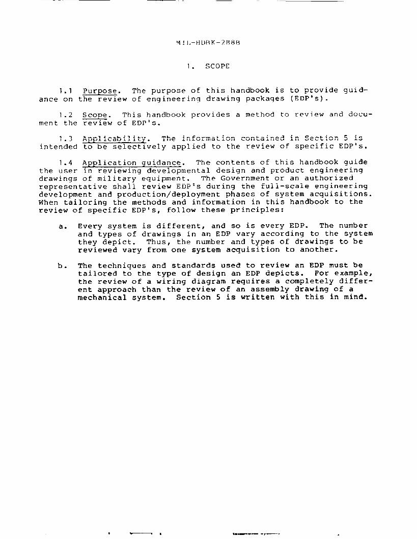
1.1 Purpose. The purpose of this handbook is to provide guid-ance on the review of engineering drawing packages (EDP’s).
1.2ment the
1.3intended
1.4the userdrawings
Scope. This handbook provides a method to review and docu-~w of EDP’s.
App liability. The information contained in Section 5 isto be selectively applied to the review of specific EDP’s.
Ap plication quidance. The contents of this handbook guidein reviewing developmental design and product engineeringof military-equipment. The Government or an authorized
representative shall review EDP’s during the full-scale engineeringdevelopment and production/deployment phases of system acquisitions.When tailoring the methods and information in this handbook to thereview of specific EDP’s, follow these principles:
a.
b.
Every system is different, and so is every EDP. The numberand types of drawings in an EDP vary according to the systemthey depict. Thus, the number and types of drawings to bereviewed vary from one system acquisition to another.
The techniques and standards used to review an EDP must betailored to the type of design an EDP depicts. For example,the review of a wiring diagram requires a completely differ-ent approach than the review of an assembly drawing of amechanical system. Section 5 is written with this in mind.
MIL-HDBK-288B
?- . APPLICABLE DOCUMENTS
2.1 Government documents.
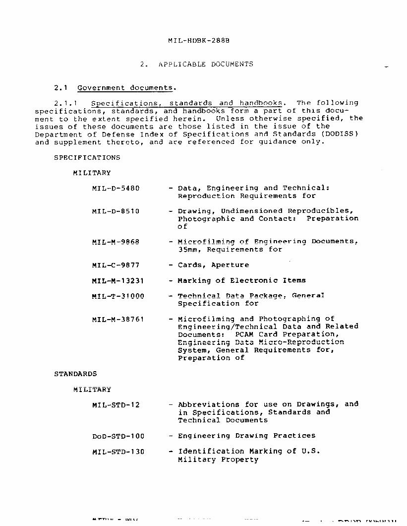
2.1.1 Specifications, standards and handbooks. The followingspecifications, standards? and handbooks form a part of this docu-ment to the extent specified herein. Unless otherwise specified, theissues of these documents are those listed in the issue of theDepartment of Defense Index of Specifications and Standards (DODISS)and supplement thereto,
SPECIFICATIONS
MILITARY
MIL-D-5480
MIL–D-8510
MIL-M-9868
MILK-9877
MIL-M-13231
MIL-T-31000
MIL-M-38761
and are referenced for guidance only.
- Data, Engineering and Technical:Reproduction Requirements for
- Drawing, Undimensioned Reproducible,Photographic and Contact: Preparationof
- Microfilming of Engineering Documents,35mmr Requirements for
- Cards, Aperture
- Marking of Electronic Items
- Technical Data Package, GeneralSpecification for
- Microfilming and Photographing ofEngineering/Technical Data and RelatedDocuments: PCAM Card Preparation,Engineering Data Micro-ReproductionSystem, General Requirements for,Preparation of
STANDARDS
MILITARY
MIL-STD-12 - Abbreviations for use on Drawings, andin Specifications, Standards andTechnical Documents
DoD-STD-1O() - Engineering Drawing Practices
MIL-STD-130 - Identification Marking of U.S.Military Property
MIL-HDBK-288B
MIL-STD-275 - Printed Wiring for ElectronicEquipment
MIL-STD-804 - Format and Coding of Aperture, Copy andTabulating Cards for Engineering DataMicro-Reproduction Systems
(Unless otherwise indicated, copies of federal and militaryspecifications, standards, and handbooks are available from the NavalPublications and Forms Center, (ATTN: NPODS), 5801 Tabor Avenue,Philadelphia, PA 19120-5099. )
2.1.2 Other Government documents, drawinqs, and publ ications.The following other Government documents, drawings, and publicationsform a part of this document to the extent specified herein. Unlessotherwise specified, the issues are those in effect on the date ofthis Military Handbook and are identified for guidance only.
H6 - Federal Item Name Directory for SupplyCataloging
DoD 5220.22 - Industrial Security Manual forSafeguarding Classified Information
(Cataloging Handbook H6 is available from Commander, DefenseLogistics Services Center, Battle Creek, MI 49017-3084. )
(DoD Directive 5220.22 is available from the Naval Publicationsand Forms Center, (ATTN : Code 1052), 5801 Tabor Avenue,Philadelphia, PA 19120-5099. )
2.2 Non-Government publications. The following documents form apart of this document to the extent specified herein. Unless other-wise specified, the issues of the documents which are DoD adoptedare those listed in the issue of the DODISS and in effect on the dateof the Military Handbook and are identified for guidance only.
AMERICAN NATIONAL STANDARDS INSTITUTE (ANSI)
ANSI B1.20.1 - Pipe Threads, General Purpose (Inch)
ANSI B1.20.3 - Dryseal Threads (Inch)
ANSI Y14.1 - Drawing Sheet Size and Format
ANSI Y14.2 - Line Conventions and Lettering
ANSI Y14.3 - Multi and Sectional View Drawings
ANSI Y14.5 - Dimensioning and Tolerancing
ANSI Y14.6 - Screw Thread Representation
MIL-HDBK-288B
ANSI Y14.7.1 - Gear Drawing Standards: Part 1 forSpur, Helical, Double Helical andRack
ANSI Y14.7.2 - Gear and Spline Drawing StandardsPart 2 - Bevel and Hypoid Gears
ANSI Y14.13 - Mechanical Spring Representation
ANSI Y14.15 - Electrical and Electronic Diagrams
ANSI Y14.34 - Parts Lists, Data Lists and Index Lists
ANsI/IPc-D-350 - Printed Board Description in DigitalForm
(Applications for copies should be addressed to the AmericanNational Standards Institute, 1430 Broadway, New York, NY10018-3308. )
IEEE STD 91 – Standard Graphic Symbols for LogicFunctions
IEEE STD 315 - Standard Graphic Symbols for Electricaland Electronics Diagrams
(Applications for copies should be addressed to the Institute ofElectrical and Electronic Engineers, 345 East 47th Street, New YorkrNY 10017.)
,. --- — -
MTL-HDBK-288B
3.1 Definition of terms.
3.1.1 Altered item drawing. An engineering drawing whichdepicts the alteration of an existing item from its originalconfiguration. An altered item drawing depicts complete details ofthe alteration.
3.1.2 Assembly drawinq. An engineering drawing that depicts anumber of Parts or subassemblies joined together to perform a speci-fic functi~n. An assembly drawing depicts-the details of how theparts or subassemblies are joined and interact.
3.1.3 Associated list. A tabulation of pertinent engineeringinformation pertaining to an item depicted on an engineering drawingor a set of engineering drawings. Examples include parts lists,index lists, and data lists.
3.1.4 Commercial item. An article regularly used for other thanGovernment purposes, which is advertised or cataloged as availableon an unrestricted basis for sale or traded in the course of normalbusiness operation.
3.1.5 Contract data requirements list (CDRL), DD Form 1423. Alist of data requirements that are authorized to be acquired for aspecific acquisition, which is made a part of the contract.
3.1.6 Contracting officer. My person granted the authority toenter into and administer contracts on behalf of a Government agency.The term includes any individual who is delegated such authority.
3.1.7 Contractor. Any individual, partnership, public orprivate organization or other entity which is a party to a contract.
3.1.8 Data item description (DID), DD Form 1664. A completedform that defines the data required of a contractor. The formspecifically defines the data content, preparation instructions?format and intended use.
3.1.9 Desiqn activity. A Government activity or a contractorwhich is responsible for the design of an item and future maintenance(change control) of the master documentation.
3.1.10 Detail drawinq. An engineering drawing which depictscomplete details of an item or assembly.
3.1.11 Engineering drawinq. A document which providessufficient information to manufacture an acceptable part; assemble agroup of parts or describe the desired parameters required topurchase an existing part. This information can be provided in textor graphic form or a combination of both.
MI L-H DBK-2R8B
3.1.12 Enqineerinq drawinq packaqe (EDP). A collection ofproduct related engineering drawings and associated list inaccordance with MIL–T-31OOO and relating to design, manufacturer testand inspection of an item or system.
3.1.13 Enqlneering study (ES). A document. prepared by thereviewing activity that documents discrepancies noted during anin-process or final review of an EDP.
3.1.14 Existinq item. An item in-being and operational prior tothe time of need.
3.1.15 Monodetail drawinq. A monodetail drawing delineates asingle part.
3.1.16 Multidetail drawing. A multidetail drawing depicts twoor more uniquely identified parts.
3.1.17 Reviewinq activity. The Government activity assigned toperform in-process or final technical reviews of EDP’s.
3.1.18 Selected item drawinq. An engineering drawing thatdepicts an existing standard, or design, or vendor activity item uponwhich further required selection or restriction for fit, tolerance~performance or reliability is placed. (See DoD-STD-1OO for completerequirements. )
3.1.19 Source control drawinq. ~ engineering drawing thatdepicts an existing commercial or vendor item which exclusively pro-vides the performance? installation, and interchangeable characteris-tics required for one or more specific critical applications. (SeeDoD-STD-1OO for complete requirements. )
3.1.20 Specification control drawing. w engineering drawingthat depicts an existing commercial vendor-developed item advertisedor cataiogued as available on an unrestricted basis on order as anoff- the-shelf item; or an item, while not commercially available, isprocurable on order from a specialized segment of industry. (SeeDoD-STD-1OO for complete requirements. )
3.1.21 Technical data packaqe (TDP). A collection of productrelated engineering data comprised of the EDP and non-EDP datarelated to the design and manufacture of the item or system. The EDPcontains all the descriptive documentation needed to ensure thecompetitive reprocurement of an item or system. The non-EDP consistsof data such as system and development specifications product speci-fications, concurrent repair parts list, packaging data sheetsspecial production tool data, acceptance inspection equipment data~military specifications and standards, repair manuals, supplementaryquality assurance provisions, preparation for delivery requirementsand other data as required.
u m
?41L-HDBK-288B
3.2 Acronvms used in this handbook. The acronyms used aredefined as follows:
a.
b.
c.
d.
e.
f.
9“
h.
i.
j.
k.
1.
m.
n.
o.
P*
q“
r.
ADPS
AR
CDRL
DCAS
DFARS
DID
DL
DoD
DoDD
DoDISS
EDP
ES
IL
PL
SCD
SOCD
TDBD
TDP
Automatic Data Processing System.
As Required.
Contract Data Requirements List.
Defense Contract Administrative Service.
DoD Federal Acquisition Regulation Supplement.
Data Item Description.
Data List.
Department of Defense
DoD Directive.
DoD Index of Specifications and Standards.
Engineering Drawing Package.
Engineering Study
Index List.
Parts List.
Specification Control Drawings.
Source Control Drawings.
Top-Down-Break-Down.
Technical Data Package.
MI L-HDBK-288B
4. GENE~L REQUIREMENTS
4.1 EDP. If not already in existence, some form of engineeringdrawing w~ be prepared by the manufacturer or system developer atthe start of a program. During the concept/exploration and demon-stration/validation stages of system development, the drawing packagemay contain only enough detail to permit design evaluations and costprojections. As the design progresses and the program moves throughfull scale engineering development and finally into production, thedrawings become more and more detailed. The types of drawingsdescribed in MIL-T-31OOO enable the EDP to follow this progressionfrom design concept to production. They are:
a. Conceptual design drawings and associated lists.
b. Developmental design drawings and associated lists.
c* Product drawings and associated lists.
4.2 Reviewinq the EDP. From its inception to its disposal, theEDP is a dynamic set of documents. As a program progresses, designchanges are made? manufacturing difficulties are encountered, tech-nology changes, and drawing errors are located. All of these eventsrequire the design activity to change the EDP. Regardless of thereason for changes, the EDP must be continuously reviewed to ensurethat it accurately depicts the article in its current configuration.
4.3 Principal phases of EDP reviews. The principal phases ofthe review process for EDP’s are:
a. Selection of reviewing activity and review of contractrequirements.
b. Contractor indoctrination.
c, Technical reviews.
d. Documenting contractually deficient engineering data.
e. Final review.
f. Recommending acceptance or rejection of the EDP.
4.4 Reviewing activity.
4,4.1 Familiarity with requirements. Everyone who reviews EDP’sshould become thoroughly famlllar with the drawing requirements inapplicable Government specifications and standards. This handbookaids in performing EDP reviews by reminding the reviewer of some ofthe more important requirements to be reviewed on the most frequentlyencountered drawings. EDP’s should be reviewed by experts in thetype of item or assembly depicted.
MIL-HDBK-288B
4.4.2 Reviewinq the CDRL. The contract is the most importantdocument controlling the EDP. Each requirement for the EDP is pre-pared in the form of a Data Item Description (DID), DD Form 1664.The DID’s are listed on a Contract Data Requirements List (CDRL), DDForm 1423, which is appended to the contract. It is essential thatthe DID’s and the CDRL’S adequately and accurately describe therequirements for the EDP, including the type of drawings, tailoringrequirements, associated lists, formats, and delivery schedules. Thepersons assigned to review an EDP should be familiar with all con-tract requirements that affect the EDP. This includes such provi-sions as rights-in-data clauses, data warranty clauses and parts con-trol requirements, as well as design specifications.
4.5 Contractor indoctrination. Government personnel assigned toperform the technical review of the EDP must understand the contract,and the contractor must agree with them on what is required for eachdeliverable. Both parties should meet as early in the contractperiod as possible and review contract requirements together. Anydisagreement over the interpretation of the contract should immedi-ately be brought to the attention of the procuring activity’s programoffice for resolution. This indoctrination may not be needed whenfollow-on contracts are awarded to the same contractor, or when thecontractor is already working on more than one project for the sameGovernment procuring activity. The reviewing activity and the con-tractor should discuss the following topics when they meet:
a.
b.
c.
d.
e.
f.
9*
h.
i.
The contractor’s drafting practices and drawing formats.
The contractor’s quality assurance and configuration manage-ment procedures for preparing checking, controlling andrevising EDP’s.
Types of lists (index, data, wire, and parts) to be fur-nished.
Approximate number of drawings to be furnished.
Security classification of drawings or data.
Contractor proprietary rights over any drawing or associateddocument in the EDP. The contract must specify the extent ofcontractor rights-in-data.
Whether the contractor plans to use existing drawings or dataas part of the EDP. If so, ensure that they are acceptableto the Government.
Types of drawinqs to be furnished by the contractor for off-the-shelf items:
Under what conditions specification and source control draw-ings shall be used and will be accepted.
MI1.-HDE3K-288B
j.
k.
1.
m.
n.
o*
P*
q*
r.
s*
If wire harness drawings will be furnished under the con-tract. If so, consider using them as templates for makingwire harnesses, in order to reduce manufacturing costs.
Types of drawings to be used for documenting printed circuitsand requirements for master pattern drawings.
The use of Government and industry standard parts wheneverpossible.
Contractor provisions for test specifications in the EDP.
procedures for incorporating approved engineering changes inthe EDP.
Whether the EDP will be used as supplementary provisioningtechnical documentation.
Flow-down of drawing requirements to subcontractors and lowertier contractors. The prime contractors must ensure that alldrawings conform to contract requirements, including thoseprepared by subcontractors and lower tier contractors.
Government procedures for reviewing the EDP and documentingdeficiencies.
Contractor procedures and time limit to respond to Governmentcomments and correct deficiencies in the EDP.
Contractor’s procedures for ensuring traceability of drawingrequirements ~o production and related media (process sheets?route sheets, tooling? jigs, etc.).
4.6 Technical reviews of the EDP. Government agencies conductin-process technical reviews to monitor the preparation of EDP’s andto evaluate the technical content of individual drawings or entireEDP’s.
4.6.1 Surveillance of drawinq preparation. It is essential thatthe Defense Contract Administrative Service (DCAS) or other Govern-ment reviewing activity monitor drawing preparation. An active draw-ing surveillance program brings technical or managerial problems tolight early in the acquisition program, thus avoiding potentiallycostly and time-consuming errors. The surveillance program shouldinclude inspections of procurement? manufacturing, and test facili-ties to ensure that the drawings, or documents developed from thedrawings, are used in the functions for which they are prepared.
4.6.2 Reviewing for technical content. Technical reviews ofengineering drawings vary according to the type of drawings and thesystem or item they depict. Section 5 contains guidance for review-ing the most frequently encountered types of engineering drawings
MI L-HDF3K-288B
and associated lists. Each reviewing activity should establish itsown sampling level for EDP reviews. Normally, d detailed review of15 percent to 20 percent of the total package is sufficient to revealthe types of deficiencies to be found throughout. However, reviewingactivities may elect to conduct more extensive reviews of smaller orextremely complex drawing packages. All dr~wings should be reviewedfor compliance with rights-in-data clauses of the contract. Anydrawings found to be noncompliant shall be rejected. Before review-ing an entire EDP or all the drawings for an entire assembly, firstconduct a completeness review to ensure that all required drawingsand supporting data have been furnished. See 4.8.2 for instructionson how to conduct a completeness review.
4.6.3 Follow-on review. The Government reviewing activityshould meet with the contractor as needed to discuss, explain, andresolve the discrepancies noted in the ES (see 4.7). The contractorshall revise the drawings as required and submit corrected drawingsto the Government for review. The Government reviewing activityshall conduct follow-on reviews of new or corrected engineering draw-ings to ensure that they are acceptable. Additional engineeringstudies should be prepared as needed to document discrepancies notedin follow-on reviews. Any discrepancies that cannot be resolvedshould immediately be brought to the attention of the project managerof the procuring activity. During this review cycle, the reviewingactivity should coordinate with the activity performing or witnessingconfiguration audits to ensure that all drawing discrepancies notedduring the audits are corrected.
4.7 Es. The Government reviewing activity shall prepare an ESto docume~ the results of the technical review. The ES lists dis-crepancies discovered during the technical review. The ES is notintended to be a stand alone document and although the comments shallbe written in a clear and complete manner, there will be occasionswhen the engineering drawings must be viewed in order to completelyunderstand the ES.
4.8 Final review. The final review is conducted on the contrac-tor’s final deliverable under the contract. The final deliverable,which may be in the form of original drawings, microfilm~aperturecards, nonreproducible hardcopies, digital data, or any combinationthereof, should not be submitted to the Government until the techni-cal reviews have been completed and the drawings found technicallyacceptable. The final review should ensure the following:
a. Previously documented discrepancies have been corrected,
b. The final deliverable is a complete package, and
c. The media on which the final deliverable is submitted con-forms to the contractual requirements.
MIL-Hr)BK-288B
4.8.1 Review of previously documented discrepancies. A sampling _of the final deliverable should be reviewed to ensure that previouslydocumented discrepancies, which the contractor had agreed to correct,were in fact corrected. ES’s from previous technical reviews shouldbe used as guides to verify the correction of previously noted dis-crepancies.
4.8.2. Review for completeness. Also known as a top-down-break-down (TDBD), the completeness review is performed to ensure that theEDP contains all the-documents necessary to produce the system oritems depicted. The TDBD is begun by e-xamining the engineering draw-inq which depicts the entire assembly, end item~ or system. Thisfirst-tier, or top drawing, lists second-order documents such asdetail drawings, parts lists, and specifications. These second-tier,documents may be listed in drawing notes, parts lists, materialblocks, or anywhere else on the face of the drawing. Therefore, areview of parts lists alone is not sufficient to complete a TDBD.Each lower tier document may in turn list additional drawings, lists,or specifications. Each must be reviewed in the same manner, untilall documents belonging to the EDP have been examined. An indexlist, data list, or indentured (used on) list can be helpful in per-forming the TDE3D. If none of these lists are available, a list canbe hand-generated to keep track of all cross-references. All docu-ments cited in a drawinq or associated list shall be furnished aspart of the EDP except ~or industry specifications and standards,military specifications and standards, or documents referenced paren-thetically. The drawing package is not complete unless this require-ment is met. The EDP should also be checked against the requirementsof the CDRL and the standardization documents cited in each applica-ble DID. This review is not conducted for technical substance, butrather to identify and locate all documents required by the contract~
4.8.3 Review of drawinq media. This review is conducted toensure that the media materials, legibility, and reproductive qualityconform to the applicable contract requirements and specifications.
4.8.3.1 Oriqinal drawings. If the contract specifies originaldrawings as the final deliverable, a sampling of the package shouldbe examined for compliance with MIL-D-5480, MIL-D-851O and DoD-STD-100. Particular attention should be paid to the legibility of lines,numbers, letters and character data? and to the reproducibility ofthe drawings. The reviewing activity should also ensure that whenoriginal drawings are ordered, original drawings are receivedoDuplicate originals shall not be delivered to the Government (seeDoD-STD-1OO) .
4.8.3.2 Master pattern drawinqs. When the contract requiresmaster patterns to be delivered as part of the drawing package, theyshould be reviewed for compliance with DoD-STD-1OO and MIL-STD-275.
4.8.3.3 Microfilm/aperture cards. If the contract specifies afinal deliverable in the form of microfilm copies of the drawing
.-
!uIIL-HDBK-288B
package mounted in aperture cards, the media should be reviewed forcompliance with MIL-M-9868, MIL-C-9877, MIL-M-38761, and MIL-STD-804.A sampling of the microfilm should be examined to ensure that thetype, class, and kind (if applicable) are in accordance with MIL-M-9868 as contractually imposed. The entire microfilm package shouldbe reviewed for quality, density, and resolution. Aperture cardsshould be reviewed to ensure that they are of the correct type~class, and kind; that the microfilm is mounted correctly; that theheader information printed on the cards reflects the drawing depictedon the microfilm; and that the information punched on the card agreeswith the header information.
4.9 Recommending acceptance or rejection.
4.9.1 Acceptance of the EDP. The Government procuring activityshall ensure that all reviews of the EDP have been completed before
,
recommending acceptance. If the reviewing activity determines thatthe EDP meets contract and specification requirements, a letterindicating technical approval is sent to the contractor via thecontracting officer for notification of technical approval. Theaccepting activity which is listed as the first addressee in block 14of the CDRL, will provide the final acceptance signature on the DDForm 250 after data delivery from the contractor.
4.9.2 Rejection of the EDP. The El)Pshould be rejected if in-process, technical, or final reviews reveal noncompliance with con-tractual and specification requirements. If the reviewing activityrecommends rejection~ it shall notify the designated accepting activ-ity by letter, with a copy of the ES to justify its recommendation.When the reviewing activity recommends rejection? the contractingofficer may elect to invoke the withholding of payment clause in thecontract. The contracting officer shall notify the contractor byletter that the EDP has been rejected, and attach a copy of the ES asjustification. In any event, the contractor should be allowed areasonable period, specified in the CDRL, to correct the EDP andresubmit it for Government review/acceptance.
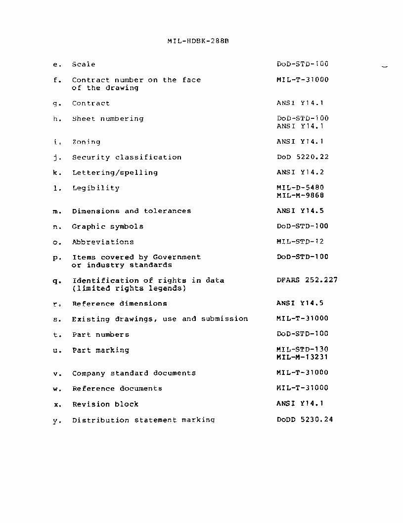
4.10 General quidance for reviewing EDP’s. The following itemsshould be reviewed on all developmental design and productiondrawings:
a.
b.
c.
d.
QE& Controlling Document
Drawing size and format ANSI Y14.1
Drawing title (nomenclature) DoD-STD-loo”H6
Drawing number DoD-STD-1O()
Drafting, approval and release ANSI Y14.1record
MIL-HDBK-288B
e.
f.
9*
h.
.1.
j-
k.
1.
m.
n.
0.
P“
q*
r.
s.
t.
u.
v.
w.
x.
Y“
Scale
Contract number on the faceof the drawing
Contract
Sheet numbering
Zoning
Security classification
Lettering/spelling
Legibility
Dimensions and tolerances
Graphic symbols
Abbreviations
Items covered by Governmentor industry standards
Identification of rights in data(limited rights legends)
Reference dimensions
Existing drawings, use and submission
Part numbers
part marking
Company standard documents
Reference documents
Revision block
Distribution statement marking
DoD-STD-1OO
MIL-T-31OOO
ANSI Y14.1
DoD-STD-loo”ANSI Y14.I
ANSI Y14.1
DoD 5220.22
ANSI Y14.2
MIL-D-5480MIL-M-9868
ANSI Y14.5
DoD-STD-loo
MIL-STD-12
DoD-STD-loO
DPARS 252.227
ANSI Y14.5
MIL-T-31OOO
DoD-STD-loo
MIL-STD-130MIL-M-13231
MIL-T-31OOO
MIL-T-31000
ANSI Y14.1
DoDD 5230.24
MI L-H DBK-288B
5. DETAILED REQUIREMENTS
5.1 Reviewinq for correct material and mechanical specifica-tions.
5. 1.1 Material specifications. See DoD-STD-1OO.
a.
b.
co
d.
e.
f.
9.
h.
i.
j.
Make sure that material specifications are listed on thedrawing.
Check material specifications. Ensure requirements such asclass~ grade, and type are specified Ensure active specifi-cations are used.
Ensure that the material specification correctly identifiesthe shape required, such as bar~ sheet, rod, or tubing.
The tolerance and surface finishes given on specificationsfor commercial items must agree with those shown on the draw-ing for nonmachined dimensions,
Evaluate qualities in regards to plating, painting, weldingand hardening.
Industry standard stock materials must be specified, whenpractical.
Ensure that proper material is used on die formed parts.Some heat treated materials are not practical for die form-ing. Other materials are suitable and aging will meet hard-ness requirements.
Ensure that material has been specified in the proper condi-tion to facilitate machining operations.
Check the type of raw material for compatibility with pro-cessing and machining techniques, stress requirements anddirect contact with dissimilar materials.
Check the drawing notes for heat treatment and hardnessspecifications and requirements.
5.1.2 Castinqs and forqinqs. Check the following items:
a. Ensure that there are separate drawings of a rough casting orforging and the finished part.
b. Make sure that the drawings specify the type of forging orcasting to be used.
c. Ensure the drawings specify draft allowance.
—-.. —-=.————->———-— —..—...
d.
e.
f.
9“
h.
i.
jw
k.
1.
m.
MI L-Hr)BK-288B
Specified tolerances must be compatible with the type ofcasting or forging and its intended use.
Datum planes must be specified.
Ensure that the location and dimensions of tooling points arespecified.
Dimensions of draft surfaces must be taken from mold lines.
Duplicate dimensions should not be shown on both the roughand finished part drawing unless one of the dimensions isshown as reference.
Ensure that the grain direction of forging is indicated onthe drawing.
Ensure that all materials, incuding alloy% are proPerlYspecified. See DoD-STD-1OO.
Ensure that drawings specify the parting lines of castings.
Ensure that the drawings show the location and dimensions oftest coupons on forgings or castings.
Ensure that inspection procedures are specified for the cast-ings or forgings shown on the drawings.
5.1.3 Mechanical specifications. See DoD-STD-loo.
5.1.3.1 General requirements.
a.
b.
c.
d.
Check fits between all mating parts to ensure that maximumtolerance build-ups will allow parts to assemble and operatewithout interference.
Check to ensure that any feature or dimensions requiringspecial tooling are so identified and that the specialtooling is defined in the EDP.
All machining requirements such as chamfers~ countersinks~counterbores, and radii must be properly defined and speci-fied.
Check to ensure that all mating holes for connecting hardwaresuch as rivets and bolts are within tolerance limits.
5.1.3.2 Thread data. In addition to the specified requirementsof ANSI Y14.6, check thread data for the following:
—-
MI L-H DHK-28813
a.
h .
c.
d.
e.
f.
Ensure that general purpose pipe threads are not used aspressure seals. General purpose pipe threads require a seal-ing compound. Dryseal pipe threads do not require a sealant.See ANSI B1.20.3 and ANSI B1.20.1.
Ensure adequate thread engagement. Bolts must be long enouqhto provide sufficient thread engagement for washers, nuts,and safety wire~ as appropriate.
Thread designation, appropriateness of selected threadtolerance class, and resulting class of fit with threads ofmating part, use of thread inserts and thread insertinstallation notes.
Ensure the first thread is countersunk or chamfered.
Check uniformity in depth of tap drills and thread depth forgreater efficiency in production. Blind tap holes should beavoided, if possible.
Ensure that tread nomenclature format is correct.
5.1.3.3 Sprinq data. In addition to the specific requirementsof ANSI Y14.13, check spring data for the following information:
a. Ensure that the drawings specify the type of springs to beused.
b. Wherever possible, springs that conform to an acceptedGovernment or industry specification or standard should beused.
c. Where nonstandard springs are used, ensure that the drawingsdepict their wire diameter, mean spring diameter, springrate, unstressed length, stressed length, and finish.
5.1.3.4 Gear data. In addition to the specific requirements ofANSI Y14.7.1 and ANSI Y14.7.2, check gear data for the following:
a. Ensure that drawings specify the type of gears to be used.
b. Wherever possible, gears that conform to an accepted Govern-ment or industry specification or standard should be used.
co Where nonstandard gears are used, ensure that the drawings
depict their pitch, pitch diameter~ helix angle? pressureangle, shaft diameter? thickness, material used, finish, andany special lubrication requirements.
5.1.3.5 Bearinq data. Check bearing data for the followinginformation:
a.
b.
c.
MIL-HDBK-288B
Ensure that the drawings describe the types of bearing to beused and their rated life.
Wherever possible, bearings that conform to an acceptedGovernment or industry standard or specification should beused.
Where nonstandard bearings are used, ensure that the drawingsdescribe their dimensions, load rating, life rating, materialrequirements, speed and lubrication requirements.
5.1.4 Sheet metal data. Check for the minimum bend allowanceand dimensions of parts formed from sheet metal. Drawings shouldshow dimensions from outside mold lines. To eliminate the need forcalculations, drawings should show the true dimensions of bend allow-ances instead of angle dimensions. See ANSI Y14.5. Complicatedsheet metal and weldment parts should be replaced with die andinvestment castings wherever practical. Evaluate stamping, extrudingor fabricating in lieu of casting and forgings. Ensure that weldingrequirements conform to applicable standards.
5.1.5 Platinq and finishing data. Check plating and finishing,requirements for the followlng:
a.
b.
c.
d.
e.
f.
9*
5.2
a.
Ensure that tolerance and thickness are in accordance withthe applicable plating specification.
The drawings must specify the dimensions, surface finish~waviness and lay requirements of plated parts~
precious metal plating requirements should be eliminatedwhere practical to reduce cost.
Avoid plating only selected portions of parts wherever possi-ble.
Drawings must specify if metal parts will be deoxidized,anodized, chemically filmed, barrier coated, sacrificialcoatedt or treated in some other manner~ If more than onetreatment method is specified, ensure that the treatments areapplied in the proper order.
Check drawing notes to make sure that magnetic inspection isrequired for high stress heat treated parts and low microfin-ish parts prior to grinding.
The drawing must indicate if dimensions apply before or afterthe plating is applied.
Reviewinq assembly drawings. Check the following:
Ensure that the locations of name plates are shown.
.
b.
c.
d.
e.
f.
9’
h.
i.
j-
k.
1.
m.
n.
o*
MIL-HDBK-288B
Assembly drawings must show all peculiar assembly or adjust-ment instructions.
Ensure that the assembly drawings refer to all associateddocuments and drawings.
There must be sufficient views to show the relationshipbetween each part.
Assembly part numbers must be properly marked.
Assembly drawings must show power input and output values andthe applicable tolerance thereto.
Ensure that inspection and test requirements are specifiedfor items depicted in the drawing.
Assembly drawings must identify inseparable assemblies.
Ensure that assembly drawings identify and depict attachinghardware such as nuts, bolts, and rivets.
Location and orientation of parts must be shown.
Ensure that tolerance build-ups do not cause interferenceduring assembly, disassembly and operation.
Ensure that required quantities are correct.
Assembly drawings must depict correct assembly and referencedimensions.
Ensure that the reference designators used on the assemblydrawing are used consistently on all associated drawings andrelated lists.
The identification and quantity of parts shown on the assem-bly drawing must agree with the parts lists.
5.3 Reviewinq detailed drawinqs. See ANSI Y14.3. Check thefollowing:
a.
b.
c.
d.
Detailed drawings must completely depict the entire part orassembly shown.
Ensure that there are sufficient views to adequately definethe item.
Ensure that all dimensions are taken from physical features.See ANSI Y14.5.
Detail drawings should not show the dimensions of hiddenlines. See ANSI Y14.5.
YIL-HDBK-288B
e. Ensure that datum planes are properly defined. See ANSIY14.5.
f. Ensure that monodetail drawings depict only one item.
5.4 Reviewinq drawings of electrical and electronic systems.
5.4.1 General. See DoD-STD-1OO and ANSI Y14.15. Review alldrawings of electrical and electronic systems for the followinginformation :
a.
b.
c.
d.
e.
f.
9*
h.
i.
j.
k.
1.
m.
Ensure that wires are properly identified by size, specifica-tions, and coding.
Sleeving must be properly identified. Sleeving should beover connections to ensure adequate protection where a possi-bility of shorting exists.
Check notes for correct soldering specifications.
Check that floating connectors are used only where necessary.
Check for conformal coating, where required, to provideadequate resistance to leakage.
Check that the drawings show the polarity of diodes andcrystals.
The orientation of transistors and other parts must be speci-fied with respect to a fixed reference point.
Check for hermetic sealing of connectors, where required.
Check to see that requirements for lacing, sleeving or wrap-ping are identified.
Analyze and evaluate assembly drawings, wiring diagrams,printed wiring board drawings, and schematic diagrams forcompatibility. Each drawing or diagram should refer to allrelated drawings or diagrams. All reference designators mustbe consistent.
Analyze and evaluate the service rating on all connectors.Ensure that all connectors are compatible.
Analyze and evaluate all components for safety.
Ensure that adequate test requirements are provided for alllevels of electrical or electronic assembly drawings.
5.4.2 Wirinq diagrams and wirinq harness drawinqs. Check thefollowing:
B,,< 1
a.
b.
c.
d.
e.
f.
9*
h.
i.
MI IJ-HDBK-288F3
Wiring diagrams and wiring harness drawings should be usedwhere appropriate. see I-)C)D-STD-1OO.
The physical arrangement of wire routing components should beconsistent with their layout in associated drawings.
Ensure that component terminals are identified in wiringdiagrams. Drawings must conform to ANSI Y14.15.
Ensure that the use of reference designators is consistentwith related drawings.
Ensure that wiring diaqrams identify all input and outputsignals.
Ensure that wiring diagrams identify the functions of alltest points.
Ensure that the drawing identifies grounds and shows theirlocation.
Wiring diagrams must refer to associated assembly and schema-tic drawings.
Make sure that the drawinqs detail the use of wire numbers orcolor codes, and that their use is consistent with that ofrelated drawings and associated lists.
5.4.3 Schematic, logic and interconnection diagrams. Check thefollowing:
a.
b.
c.
d.
e.
f.
9-
Ensure that diagrams are prepared for each subunit.
Diagrams must identify inputs and outputs and show applicabletolerances.
Ensure that parts are shielded where grounded.
Ensure that diagrams show the directional alignment of allcomponents, and that it is consistent with what is shown onassociated documents. This is especially important for com-ponents which are affected by polarity, such as batteries,diodes, and rectifiers.
Separately replaceable assemblies must be identified by anappropriate reference designator.
Ensure that all components are identified by reference desig-nator and type number per IEEE STD 315.
Ensure that schematic drawings show the capacity ratings ofsafety devices such as fuses and circuit breakers.
h.
i.
j“
k.
1.
m.
MI L-HDf3K-288F3
Values, ratings, and tolerances must be shown for all compo-nents.
Ensure that schematic drawings identify the functions of testpoints.
Logic symbols must be in accordance with IEEE STD 91.
Ensure that electronic symbols are uced per IEEE STD 315.
Ensure that schematic drawings refer to associated drawings.
Ensure that terminals of relays, plugs, and other connections—are identified.
5.4.4 Printed wirina board drawinas. Check the followinq:
a.
b.
c.
d.
e.
f.
9.
h.
i.
j.
Analyze and evaluate the printed wiring design for conformityto applicable specifications.
Printed wiring fabrications must conform to applicable speci-fications.
Ensure that drawings depict wiring boards in detail, andidentify all components. Drawings must conform to Section 4of MIL-STD-275.
Drawings must be laid out on a grid system.
Both sides of a wiring board, including reduction dimensions,must be shown on the same wiring board drawing. Ensure thatfront-to-back registration points are defined, preciselylocated, and adequately controlled.
Ensure that marking information depicted on the wiring boarddrawing is consistent with what is shown on associated draw-ings.
Ensure that the wiring board drawing makes reference to thecorresponding assembly drawing.
The board and assembly number must be the same as the numbersshown on the corresponding assembly drawing.
The drawing must specify and depict conformal coating, whenrequired.
Reference designators shown on the board drawing must beconsistent with those shown on the assembly drawing and asso-ciated lists.
MIL-HDBK-288B
k.
1.
m.
n.
o.
P*
q-
r.
s.
t.
u.
v.
Ensure that wiring board drawing notes include the subunitprefix.
Wiring board drawings should not contain subunit numbers.
Ensure that masking is not used as a guide for hole loca-tions.
Make sure that the dimensions and tolerances of all holes areshown. See l)oD-STD-100.
Ensure that the master pattern drawing is laid out per DoD-STD-100.”
When wiring board drawings are produced in digital form,ensure that their description and format are in accordancewith ANSI/IPC-D-350.
Separate views must be shown for double sided and multi-layered boards.
Ensure that wiring board drawings include adequate qualityassurance (QA) provisions for the manufacture of the itemsthey depict (test coupons must be shown on the master draw-ing, artwork, and production master) .
Ensure that the circuitry pattern agrees with the schematicdrawing.
Ensure that fixed points on printed wiring boards are used asreferences to define the locations, width, and dimensions ofconductors.
Ensure that jumper wires are eliminated on production draw-ings .
Ensure that master patterns contain the note “For manufac-turing purposes this drawing shall not be reproduced to orfrom a reproducible that is made from other than a stablebase material”.
5.5 Reviewinq control drawinqs.
5.5.1 Specification control drawinqs (SCD).
5.5.1.1 Criteria for designation. To qualify as a SCD, the itemdepicted must meet the following criteria:
a. It must be of an unmodified commercial type, available toboth Government and industry on an unrestricted basis.
b. The item must not have been developed for use in the equip-ment represented by the drawing package under review.
c.
d.
e.
MI L-HDBK-288B
The manufacturer’s names, addresses, identification codes,and item identification numbers must be shown on the SCD.
The drawing must list two or more known sources, unless aftera search of vendor data it is dete~mined that there is onlyone source of supply.
Ensure no restrictive markings such as limited rights, copy-right legends, etc. are shown on SCD.
5.5.1.2 Reviewing SCD’S. Analyze SCD’S for the following infor-mation:
a.
b.
c.
d.
e.
f.
9*
h.
i.
They shall disclose, as applicable, item configurationdimensions of envelope, mounting and mating dimensions,interface dimensional characteristics, and their limits.
The SCD must show inspection and acceptance test require-ments, performance, reliability, maintainability, environ-mental and other functional requirements, as necessary toensure identification and adequate competitive reprocurementof an interchangeable item.
If an electrical, electronic, or other engineering circuit isinvolved, a schematic, connector or other appropriate drawingshall be included or referred to by the drawing to providesufficient information to mark external connections.
SCD numbers are administrative control numbers and shall notbe marked on the part. The SCD numbers are used to identifythe item on other drawings or documents.
Qualification testing of items in advance of procurementaction is not a prerequisite for including an item on anSCD.
If a decision cannot be made from the information available,the manufacturer of the item or activity submitting the draw-ing should be contacted to verify that the item meets thecriteria for a SCD.
All sources of supply should be checked to verify that thepart numbers listed on the drawing meet the requirements ofthe SCD, and that the items are currently available.
The manufacturer’s part number becomes the item’s identifica-tion number.
The notations “SPECIFICATION CONTROL DRAWING” and “IDENTIFI-CATION OF SUGGESTED SOURCES OF SUPPLY ...” must appear on thedrawing per DoD-STD-1OO.
. “
5.5.2 Source control drawinqs (SOCD).
5.5.2.1 Criteria for designation. A SOCD defines an item whichis procurable only from certain vendors for reasons such as thefollowinq:
a. A vendor has a special technique, Droduct, or material whichwill make his product work in a system where others will not.The key elements must be identifiable.
b. There is a specific, critical application? and substitutevendors shall not be used without prior testing~ evaluation~and approval. Critical factors may include performance,installation, interchangeability or reliability, and must bespelled out on the drawing.
5.5.2.2 Reviewing SOCD’S. SOCD requirements are identical tothose for SCD’S except for the following differences:
a.
b.
c.
d.
e.
Items must be tested and prequalified for inclusion inSOCD’S.
The drawing shall include the following notes:
“C)nly the item described on this drawing, when procured fromthe vendor(s) listed hereon, is approved by (name and addressof cognizant design activity) for use in the application(s)specified hereon. A substitute item shall not be used with-out prior approval by (name of cognizant design activity) orby (name of Government procuring activity)
Identification of the approved source(s) of supply hereon isnot to be construed as a guarantee of present or continuedavailability as a source of supply for the item described onthe drawing”.
The drawing shall list the heading “APPROnD SOURCES OFSUPPLY”, the manufacturer’s name, address, and identificationcode, and the part number of each item that has been testedand approved for use in the specific applications stated onthe drawing.
Whenever another vendor’s item is tested and qualified forthe stated applications or when a new critical application isfound and all vendor items that are cited on the drawings areapproved for use in the new critical application the drawingmay be revised to show the new vendor or application. Eachnew vendor added must be approved for all stated applica-tions.
SOCD’S become the part identification numbers and are subse-quently used to identify the item on other drawings or docu-ments. When more than one vendor is listed on an SOCD foritems that are repairable and the repair parts are not inter-
MT[,-Hr)f3K-288B
changeable between one vendor’s item and another, eachvendor’s item shall be assigned a unique suffix of t-he SOCDnumber.
Ensure that “SOCD” and the drawing number are marked on thepart. The SOCD number becomes the item’s part number. seeDoD-STD-1OO.
The drawing shall include the notation “SOURCE CONTROLDRAWING”. See Do13-STD-100.
The drawing must list the quality conformance inspection andapproval procedures for new items/additional sources.
5.5.3 Selected item drawinqs. Selected item drawing disclosurerequirements are identical to those of SCD’S except for the differ-ences listed below:
a.
b.
c.
d.
e.
The drawing must contain the notation “SELECTED ITEMDRAWING”. See DoD-STD-1OO.
Complete details of the selection criteria shall bedescribed, such as fit, tolerance, performance and reliabi-lity.
The selected item drawing shall contain sufficient informa-tion to identify that item before selection.
The part number, and the manufacturer’s name, address andidentification number shall be included in the drawing pack-age.
The original part number must be obliterated and the selecteditem identification number shall become the part number ofthe selected item itself. See DoD-STD-1OO. (This is notconsidered a part alteration.)
5.5.4 Altered item drawings. Altered item disclosure require-ments are identical to those of SCD’S and selected item drawingsexcept for the differences listed below:
a. The drawing shall include information necessary to identifythe item prior to its alteration, including the original partnumber and the name and address of the original source. Thename and address of the source need not be furnished if theoriginal part is a Government or industry standard item.
b. When a vendor activity document is referred to, the vendordata shall be submitted along with the altered item drawing.If the vendor or original design data is unobtainable, the
~qlL-HDBK-288B
altered item drawing shall contain sufficient information toidentify that item prior to its alteration.
c. The notation “ALTERED ITEM DWWING” must appear on the draw-ing. See DoD-STD-1OO.
d. The oriqinal part number must be obliterated.
e. Altered item identification numbers shall become the partnumbers of the altered items. See DoD-STD-1OO.
5.6 Reviewinq list associated with the EDP.
5.6.1 Parts list (PL’s). See DoD-STD-1OO. Check the follow-ing:
a.
b.
c.
d.
e.
f.
9*
h.
i.
j.
k.
1.
If separate PL’s are used, make sure their format is cor-rect.
If separate PLIS are used, ensure that PL numbers are cor-rect.
If an integral PL is used, ensure that the format is correct.Refer to ANSI Y14.34.
Ensure that part or identifying numbers are correct (includ-ing items controlled by military specifications).
“Find numbers” or “reference designators” used on the PL mustbe consistent with those shown on associated drawings.
PL’s may be revised only in accordance with DoD-STD-1OO.
PL’s must specify quantities on all items not identified byas required (AR).
Bulk items must be identified by a discrete identifier in-stead of quantity and a unit of measure must be specified.
Ensure that “as required” (AR) quantities are used only whereappropriate.
Items that are not adequately defined by a Government orindustry specification must be depicted on a drawing.
Ensure that parts depicted on specification control, sourcecontrol, altered item, and selected item drawings are pro-perly identified per DoD-STD-1OO.
When PL’s are produced on an automatic data processing system(ADPS), ensure that they are in the format specified by DoD-STD-10C).
k.. I
MIL-HDBK-288B
m. Ensure that every item on a drawing is called out on a PL.
n. Verify that military and industry standard part numbers cor-rectly identify the parts being used.
o. Ensure that PL nomenclature is consistent with that used onhigher assemblies.
5.6.2 Data lists (DL’s). See DoD-STD-100. Check the following:
a.
b.
c.
d.
e.
f.
9*
Ensure that the format is correct.
Ensure that the DL contains all applicable drawings, docu-ments, and associated lists.
Ensure that DL numbers are correct.
Ensure that the DL is revised per DoD-STD-1OO.
Ensure that documents are sequenced per DoD-STD-1OO.
Ensure that DL’s are prepared for each major assembly, sub-assembly, or unit as required.
Ensure that DL nomenclature is consistent with that used onthe assembly drawing.
5.6.3 Index lists (IL’s). See DoD-STD-1OO. Check the follow-ing:
a.
b.
c.
d.
e.
f.
Ensure that the format is correct.
Ensure that IL numbering is correct per DoD-STD-100.
Ensure that documents are sequenced per DoD-STD-1OO.
IL’s must be prepared for each major assembly or system asrequired by the contractual instrument in effect.
Ensure that each IL contains all applicable DL’s and IL’s.
Ensure that the nomenclatures on IL’s agree with those on theassembly drawing.
MIL-HDBK-288B
6. NOTES
(This section contains information of a general or explanatorynature that may be helpful, but is not mandatory.)
6.1 Intended use. The information contained in this handbookprovides guidance to drawing review personnel. The data in thishandbook is not intended to be a check list for non-experiencedreview personnel to check drawings with.
6.2 Subject term (key word) listing.
AssemblyAssociated listDiagramsDrawingsSource controlSpecification control
MIL-HDBK-288B
APPENDIX
PREPARING AN ENGINEERING STUDY
10. GENERAL
10.1 Scope. This appendix details a method for documenting dis-crepancies within the EDP.
20. Applicable Documents. This section is not applicable tothis appendix.
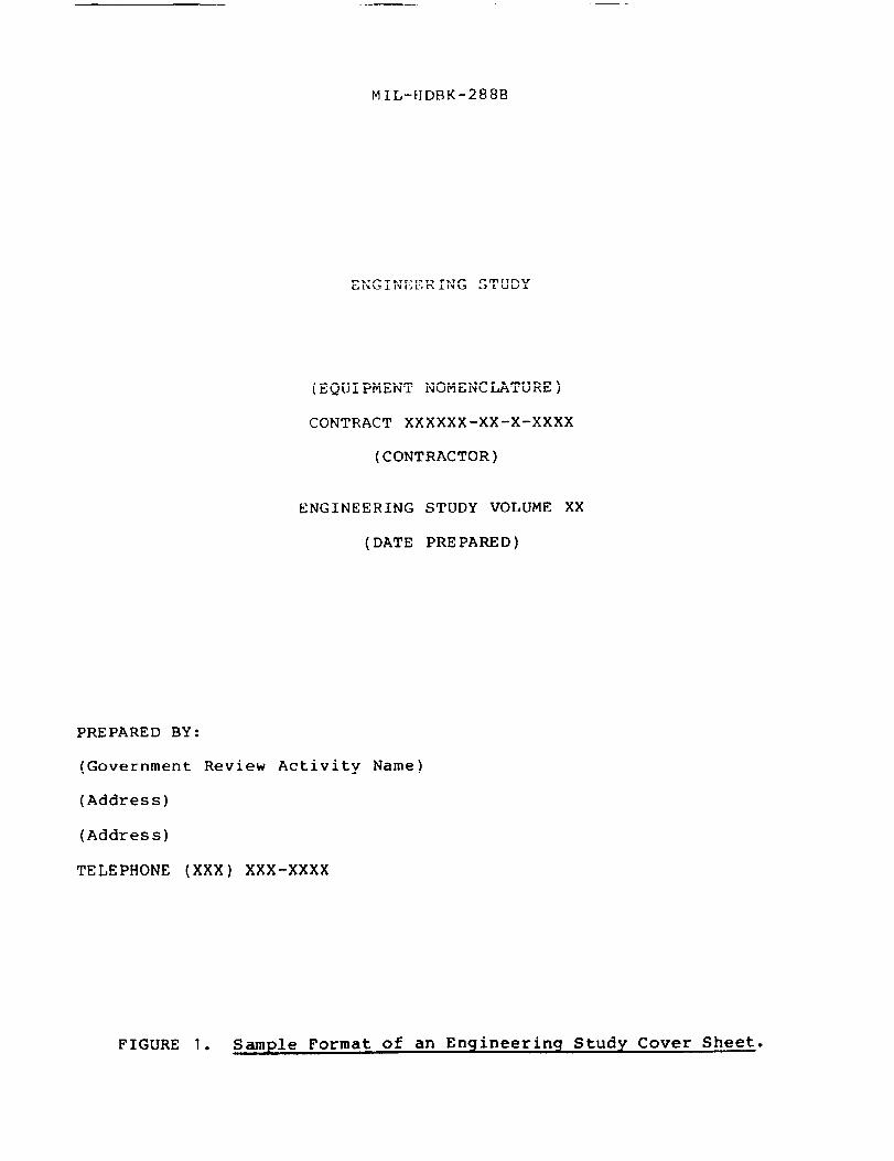
30.1 Cover sheet. The first page of the ES contains the follow-ing information (see figure 1):
a. Equipment nomenclature, contract number, contractor~ ESvolume number, and date prepared are centered on the coversheet.
b. The name of the Government reviewing activity, address? andtelephone number are located in the lower left corner of thesheet.
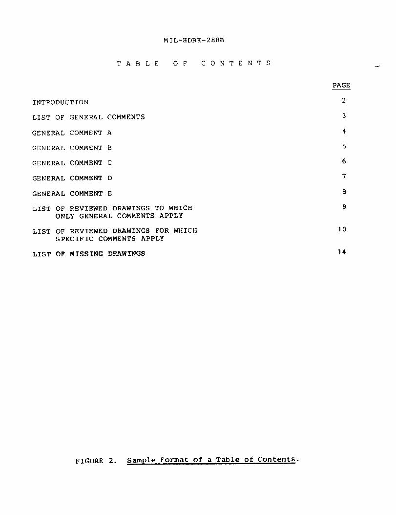
30.2 Table of Contents. The table of contents for the ES mustlist the sections of the ES against the left margin and the pagenumbers of the sections against the right margin. The title “TABLEOF CONTENTS” will be placed at the top center of the page with theheading “PAGE” under the title and against the right margin (seefigure 2).
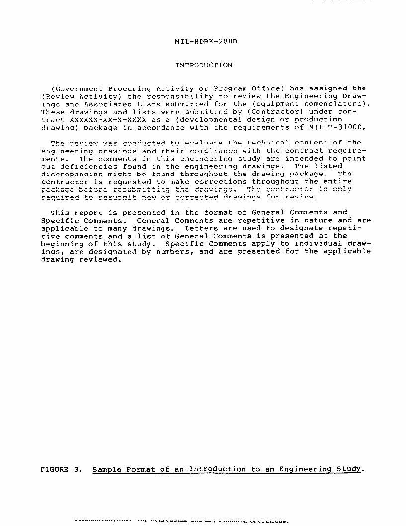
30.3 Introduction. The ES introduction contains the followinginformation (see figure 3):
a.
b.
c.
d.
e.
f.
9*
Authority for performing the review.
System nomenclature.
Contractor.
Contract number.
CDRL drawing requirements.
purpose of the technical review.
Statements indicating that comments concerning discrepantfindings may also apply to documents that were not inspectedduring the review and that the contractor is responsible toinspect the entire EDP and correct similar deficiencies.
—
MT L-H Df’3K-288B
APPENDIX
h. The scheme by which discrepancies are presented in the ES(TDBD order, numerical sequence, etc.).
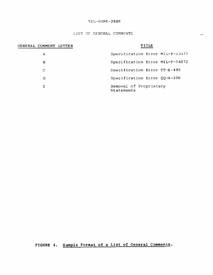
30.4 List of general comments. Comments of a repetitive nature,which pertain to three or more drawings, should be written only onceas general comments. The general comments list will precede thegeneral comments section and identify all general comments generatedduring the review. The title “List of General Comments” is placed atthe top of the sheet, and columns entitled “General Comment Letter”and “Title” will follow. Each general comment shall be assigned aletter in sequence (see figure 4).
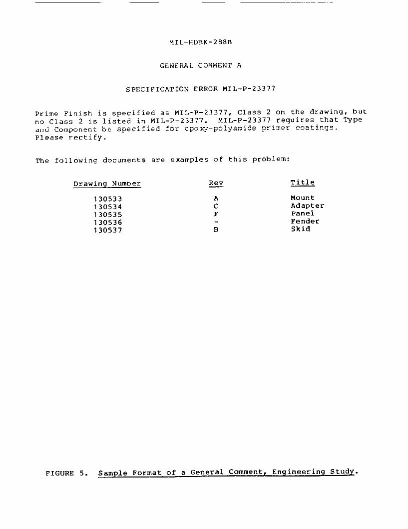
30.5 General comments. This section fully describes each discre-pancy, citing references and examples. If annotated drawings are tobe returned to the contractor, the discrepant portion of each drawingor associated document shall be annotated by the letter of the appro-priate general comment squared in red. General comment sheets shallcontain the following information (see figure 5):
a. The title “General Comment X“ (X representing the appropriateletter) shall be centered at the top of the page, along withthe title of the comment.
b. A narrative describing the discrepancy and citing the speci-fication, standard or Contract Data Requirements List whichhas been violated shall follow the title.
co The phrase, “The following documents are examples of thisproblem” shall follow the narrative, along with a list ofdrawing numbers to which the comment applies.
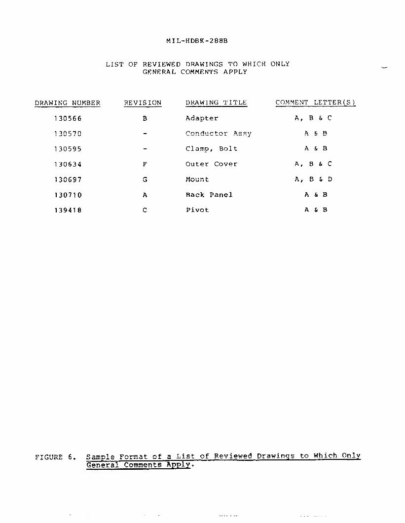
30.6 A list of reviewed drawinqs to which only qeneral comments-“ This page shall consist of the following (see figure 6):
a. The title “List of Reviewed Drawings to Which Only GeneralComments Apply” is centered at the top of the page, followedby columns titled “Drawing Number,” “Revision,” “DrawingTitle,” and “General Comment Letter(s).”
b. Drawings should be listed in alpha-numeric order.
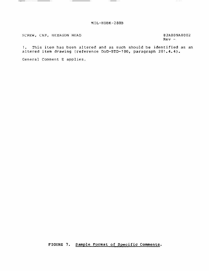
30.7 Specific comments. Specific comments shall be prepared fordiscrepancies which are not covered by the general comments. Thecomments are listed as follows (see figure 7):
a. The drawing title shall be listed in the upper left corner ofthe section.
b. The drawing number shall be listed in the upper right cornerof the section.
c.
d.
e.
f.
9“
h.
MI L-HDF3K-288B
APPENDIX
The drawing revision letter shall be listed directly underthe drawing number.
The specific comments are listed consecutively on the leftmargin by number.
The specific comments sho(]ld clearly state the problem orquestion and cite the specifications or standards which havebeen violated.
If the drawing contains general comment discrepancies, thegeneral comment letters shall be listed after the specificcomments.
The drawings are listed in alpha-numeric order.
If the comments are continued on additional pages, at the topof the continuation page in the upper left corner, list theapplicable drawing title and the abbreviation “con’t” and inthe upper right hand corner, list the drawing number alongwith the revision.
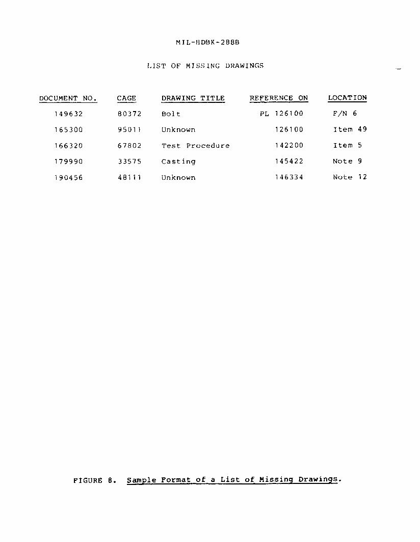
30.8 List of missing drawings. This list cites all drawings thatare required as part of the EDP but which were not furnished by thecontractor. The list is generated as a result of the TDBD (see4.8.2). This section shall consist of the following (see fi~ure 8):
a. The title “List of Missing Drawings” is centered at the topof the page, with columns titled “Document Number,” “CAGE~”“Drawing Title,” “Referenced on,” and “Location” listedbelow. The “Referenced on” column indicates what documentcites the missing document? and the “Location” column indi-cates where the missing document was cited (find number,note, or material block).
b. Missing drawings should be listed in alpha-numeric sequence.
30.9 DL/IL/PL discrepancies. Discrepancies against DL’s, IL’s,and PL’s shall be listed corresponding to the drawing number forwhich they apply (see figure 7);
30.10 Distribution of the ES. The ES should be sent to the pro-gram office responsible for the procurement of the system underreview. The program office shall forward the ES to the contractorvia the contracting officer. The reviewing activity should retain acopy of the ES and a copy of the annotated drawings until the finaldelivery of the EDP is accepted by the Government.
. . ..*C. ---- a.
MI L–HDBK-288B
ENGINEERING STUDY
(EQUIPMENT NOMENCLATURE)
CONTRACT XXXXXX-XX-X-XXXX
(CONTRACTOR)
ENGINEERING STUDY VOLUME XX
(DATE PREPARED)
PREPARED BY:
(Government Review Activity Name)
(Address)
(Address)
TELEPHONE (XXX) XXX-XXXX
FIGURE 1. Sample Format of an Engineering Study Cover Sheet.
MIL-HDBK-288B
T AB LE O F C O NT E NT S
INTRODUCTION
LIST OF GENERAL COMMENTS
GENERAL COMMENT A
GENERAL COMMENT B
GENERAL COMMENT C
GENERAL COMMENT D
GENERAL COMMENT E
LIST OF REVIEWED DRAWINGS TO WHICHONLY GENERAL COMMENTS APPLY
LIST OF REVIEWED DWWINGS FOR WHICHSPECIFIC COMMENTS APPLY
LIST OF MISSING DRAWINGS
PAGE
2
3
4
5
6
7
8
9
10
FIGURE 20 Sample Format of a Table of Contents.
MI L-HD[3K-288FJ
INTRODUCTION
(Government Procuring Activity or Program Office) has assigned the(Review Activity) the responsibility to review the Engineering Draw-ings and Associated Lists submitted for the (equipment nomenclature).These drawings and lists were submitted ‘by (Contractor) under con-tract XXXXXX-XX-X-XXXX as a (developmental design or productiondrawing) package in accordance with the requirements of MIL-T-31OOO.
The review was conducted to evaluate the technical content of theengineering drawinqs and their compliance with the contract require-ments. The comments in this engineering study are intended to pointout deficiencies found in the engineering drawings. The listeddiscrepancies might be found throughout the drawing package. Thecontractor is requested to make corrections throughout the entirepackage before resubmitting the drawings. The contractor is onlyrequired to resubmit new or corrected drawings for review.
This report is presented in the format of General Comments andSpecific Comments. General Comments are repetitive in nature and areapplicable to many drawings. Letters are used to designate repeti-tive comments and a list of General Comments is presented at thebeginning of this study. Specific Comments apply to individual draw-ings, are designated by numbers, and are presented for the applicabledrawing reviewed.
FIGURE 3. Sample Format of an Introduction to an Enqineerinq Study.
‘11[.-}{DBK-288B
—
[,1ST OF GENERAL COMMENTS
GENERAL COMMENT LETTER
A
B
c
D
E
TITLE
Specification
Specification
Specification
Specification
Error
Error
Error
Error
MIL-P-23377
MIL-F-14072
TT-E-485
QQ-A-200
Removal of ProprietaryStatements
FIGURE 4. Sample Format of a List of General Comments.
MIL-HDF3K-288B
GENERAL COMMENT A
SPECIFICATION ERROR MIL-P-23377
Prime Finish is specified as MIL-P-23377, Class 2 on the drawing, butno Class 2 is listed in MIL-P-23377. MIL-P-23377 requires that Typeand Component be specified for epoxy-polyamide primer coatings.Please rectify.
The following documents are examples of this problem:
Drawing Number Rev Title
130533 A Mount130534 c Adapter130535 F Panel130536 Fender130537 B Skid
FIGURE 5. Sample Format of a General Comment, Enqineerinq Study.
MIL-HDBK-288B
LIST OF REVIEWED DRAWINGS TO WHICH ONLYGENERAL COMMENTS APPLY
DRAWING NUMBER REVISION DRAWING ‘1’ITLE COMMENT LETTER(S)
130566 B Adapter A, B&C
130570 Conductor Assy A&B
130595 Clamp, Bolt
130634 F Outer Cover
130697 G Mount
130710 A Back Panel
139418 c Pivot
A&B
A, B&C
A, B&D
A&B
A&B
FIGURE 6. Sample Format of a List of Reviewed Drawinqs to Which OnlyGeneral Comments Apply.
———
MIL-HDBK-288B
SCREW, CAP, HEXAGON HEAD 82AO09AOO02Rev -
1. This item has been altered and as such should be identified as analtered item drawing (reference DoD-STD-1OO, paragraph 201.4.4).
General Comment E applies.
FIGURE 7. Sample Format of Specific Comments.
MI L-H DBK-288B
LIST OF MISSING DRAWINGS
DOCUMENT NO. CAGE DRAWING TITLE REFERENCE ON LOCATION
149632 80372 Bolt PL 126100 F/N 6
165300 95011 Unknown 126100 Item 49
166320 67802 Test Procedure 142200 Item 5
179990 33575 Casting 145422 Note 9
190456 48111 Unknown 146334 Note 12
FIGURE 8. Sample Format of a List of Missinq Drawinqs.
MIL-HDBK-288B
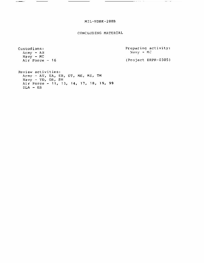
CONCLUDING MATERIAL
Custodians:Army - ARNavy - MCAir Force - 16
Preparing activity:Navy - MC
(Project DRPR-0305)
Review activities:Army – AV, EA, ER, ET, ME, MI, TMNavy - YD, OS, SHAir Force - 11, 13, 14, 17, 18, 19, 99DLA - ES
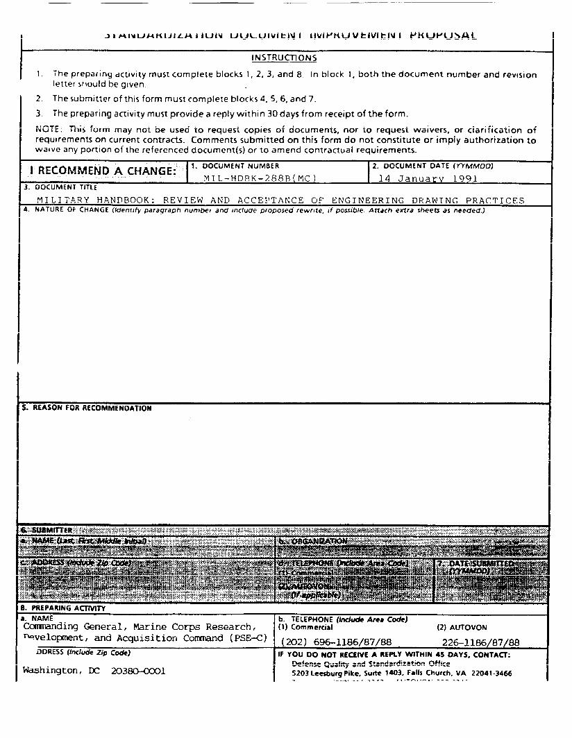
JIAIMUANUILAIIUIN uw~uivitjq I [iVIWKUVtlVlkfV I PKUPU>AL
ItNSTRUCrlONS
1. The preparing actlvlty must complete blocks 1, 2, 3, and 8 In block 1, both the document number and revlslonlettershould be given.
2. The submitter of this form must complete blocks 4,5,6,and 7.
3. The preparing activity must provide a reply within 30 days from receipt of the form.
NOTE: This form may not be used to request copies of documents, nor to request waivers, or clarification ofrequirements on current contracts. Comments submitted on this form do not constitute or imply authorization towaive any portion of the referenced document(s) or to amend contractual requirements.
I RECOMMEND A CHANGE:’J 1. DOCUMENT NUMBER 2. DOCUMENT DATE (YYMMOD)
MI L-HDBK–288B (MC) 14 Januarv 19913. DOCUMENT TITLE
MILITARY HANDBOOK: REVIEW AND ACCEPTANCE O!? ENGINEERING DRAWING PRACTICES4. NATURE OF CHANGE (/dent/fy paragraph number and Include proposed rewrite, If pos.wbie. Attach extra sheets as needed.)
. ::;;...,{<>.;y.,..;,8. PREPARJNG ACTtVITy
a. NAME b. TELEPHOfUE (tide Area Code)Comanding General, Marine Corps Research, (1)Commercial (2) AUTOVON
-velopment, and Acquisition Corrrnand(PSE< ) (202) 696-1186/87/88 226–1186/87/88DDRESS (Include Zip Code) IF YOU DO NOT RE~lVE A REPLY WITMfu 45 DAYS. CONTACT:
Defense Quality●nd Standardization OfficeWashington, ~ 20s~l S203 Leesburg Pike, Suite 1403, FaM Church, VA 22041-3466
...”+.. -.a.l. -! ., !-n,.-, -“ -----