Embed Size (px)
Citation preview
MIL-HDBK-237ANOTICE 2 (NAVY)February 14, 1992
ELECTROMAGNETIC COMPATIBILITYMANAGEMENT GUIDE FOR PLATFORMS,
SYSTEMS AND EQUIPMENTS
TO ALL HOLDERS OF MIL-HDBK-237A
1.listed:
NEW PAGE DATE SUPERSEDED PAGE
v 16 Jun 1986 vvi 20 Jan 1992 vivii 16 Jun 1986 viiviii 20 Jan 1992 viiiix/x 20 Jan 1992 ix/x41 20 Jan 1992 4142 20 Jan 1992 4243 20 Jan 1992 4344 20 Jan 1992 44119–125 20 Jan 1992 NEW
The following pages of MIL-HDBK-237A have been revised and supersede the pages
DATE
REPRINTED WITHOUT CHANGE16 Jun 1986REPRINTED WITHOUT CHANGE16 Jun 198616 Jun 19862 Feb 19812 Feb 19812 Feb 19812 Feb 1981
N/A
2. Retain this notice and insert before Table of Contents.
3* Holders of MIL-HDBK-237A will verify that page changes and additions indicatedabove have been attached. This notice page will be retained as a check sheet. Thisissuance, together with appended pages, is a separate publication. Each notice is tobe retained by stocking points until the military handbook is completely revised.
4. Changes from previous issue. The margins of Notice 2 change pages are markedwith vertical lines to indicate where changes (additions, modifications,corrections) from the previous issue were made. This is done as a convenience onlyand the Government assumes no liability whatsoever for any inaccuracies in thesenotations. Bidders and contractors are cautioned to evaluate the requirements ofthis document based on the entire content of the basic issue and Notice 1irrespective of marginal notations.
Review Activities:Navy - AS, SH, OS, TD
User Activities:Navy - YD
Preparing Activity:Navy - EC(Project No. N132)
AMSC N/A AREA EMCS
DISTRIBUTION STATEMENT A. Approved for public release; distribution is unlimited.
Downloaded from http://www.everyspec.com

Downloaded from http://www.everyspec.com

CONTENTS (CONTINUED)
40.1 Environment Profile40.2 Configurat ion40.3 Operate vs. Survive40.4 Susceptibility40.5 Future Considerations40.6 Conditions Precluding Exposure
19
B. PREDICTION AND ANALYSIS10. Introduction20. Stages of EM Prediction20.1 Concept Development and Validation Phase20.2 Full Scale Development and Production20.3 Deployment30. EM Prediction Techniques40. Applications for EM Prediction50. Types of EM Prediction
C. TAILORING GENERAL EMC STANDARDS TO EM OPERATIONAL REQUIREMENTS10. Introduction20. Operational EME30. Platform EME40. Definition of EM Operational Requirements
D. CHECKLIST10.20.30.40.50.60.60.170.70.170.270.370.480.90.100.110.
FOR MAJOR EMC T&E PLANNING CONSIDERATIONS (NAVY)IntroductionPlanning and T&E ApproachFeasibility Studies During the Conceptual PhaseAnalytical StudiesModel StudiesTest and Evaluation Master Plan (TEMP)Review Guidelines for TEMPDevelopment Test and Evaluation (DT&E)Preinstallation TestingShore-based Test Site TestingShip Construction TestingBuilders TrialsOperational Test and Evaluation (OT&E)Production Acceptance Test and Evaluation (PAT&E)Total Ship Test (TST)Aircraft Testing
E. EMC TRAINING10. Introduction20. EMC Training Responsibility30. Incorporate EMC into NTPs40. Training of Operational and Maintenance Personnel
F. FREQUENCY MANAGEMENT AND CONTROL10. Introduction20. Spectral Characteristics30. Frequency Management Considerations40. Frequency Management Plan for Platform
G. CONFIGURATION MANAGEMENT10. General20. Configuration Control Process30. Evaluation of Changes40. Required Actions
MIL-HDBK-237ANOTICE 2 (NAVY)
Page
2020202020
212121212222222223
2525252525
2727272828282829333333333334343434
3535353536
3737373738
3939394040
Downloaded from http://www.everyspec.com
MIL-HDBK-237ANOTICE 2 (NAVY)
CONTENTS (CONTINUED)
H. E3 CONSIDERATIONS IN PROGRAM DOCUMENTS10. Introduction20. Mission Need Statement (MNS)20.1 E3 Considerations for Inclusion in MNS30. Top Level Warfare Requirements Document (TLWR)30.1 E3 Considerations for Inclusion in TLWR40. Tentative Operational Requirement (TOR)40.1 E3 Considerations for Inclusion in TOR50. 0perational Requirement (OR)50.1 E3 Considerations for Inclusion in OR60. Development Options Paper60.1 E3 Considerations for Inclusion in DOP70. Decision Coordinating Paper (DCP)70.1 E3 Considerations for Inclusion in DCP During
Concept Development and Validation70.2 E3 Considerations for Inclusion in DCP During
Full Scale Development70.3 E3 Considerations for Inclusion in DCP During
Production80. Procurement Plan (PP)90. Request for Proposal (RFP)
I. EMC BIBLIOGRAPHY FOR PROGRAM MANAGERSPART I Directives and InstructionsPART II Military Specifications and Standards and Other
Related DocumentsPART III Guidance DocumentsPART IV Matrices of EMC Tasks
J. APPLICATIONS GUIDE FOR NAVSEA AND SPAWAR ACQUISITIONS
41
10.20.20.120.220.2.120.320.420.4.120.4.1.120.4.1.220.4.1.320.4.1.420.4.1.520.4.1.620.4.220.4.320.520.5.120.5.220.5.320.5.3.120.5.3.1.120.5.3.1.230.
IntroductionShip AcquisitionE3 CoordinatorE3 Program FundingE3 BudgetEMCPPEMCABParticipationShip Pro ram Managers Office (E3 Coordinator)SPAWAR E3 Office RepresentativeNAVSEA E3 and Topside Design Office RepresentativeNAVAIR E3 Office RepresentativeShip Builder and Ship Design AgentOthersMeetingsResponsibilitiesE3 Considerations in Program DocumentsStatement of Work (SOW)Specifications and StandardsRequest for Proposal (RFP)Proposal Evaluation ConsiderationCompany RelatedProposal Response RelatedElectronic and Electrical Systems or EquipmentsAcquisitions
Page
414141414141424242424243
43
43
444444
4545
475761
676767686869697070717171717172727273737374747575
77
SUPERSEDES PAGE VI OF 16 JUNE 1986
vi
Downloaded from http://www.everyspec.com
MIL-HDBK-237ANOTICE 2 (NAVY)
CONTENTS (CONTINUED)
30.130.1.130.1.230.1.330.1.430.1.530.230.2.130.2.1.130.2.1.230.2.1.330.2. 1.430.2.1.530.2. 1.630.330.3.130.3.230.3.330.3.430.3.530.430.4.130.4.230.530. 5.130. 5.2
Frequency AllocationStage 1Stage 2Stage 3Stage 4Commercial Off-the-shelf EquipmentE3 Considerations in Program DocumentsE3 RequirementsDevelopment Proposal (DP)Decision Coordinating Paper (DCP)Acquisition Plan/Acquisition StrategyRequest for Proposal (RFP)Statement of Work (SOW)S edifications and StandardsE3 Tasks During Life-Cycle PhasesConceptual or Exploratory Research PhaseValidation or Advanced Development PhaseFull Scale Development PhaseProduction PhaseDeploymentTest and Evaluation (T&E)Test and Evaluation Master Plan (TEMP)Test and Evaluation Plan (TEP)Training PlanNavy Training Plan (NTP)Factory Training
K. SHAPM STRATEGY FOR ELECTROMAGNETIC ENVIRONMENTAL EFFECTS(E3) CONTROL
10. Introduction20. Nature of technical Problem20.1 Identifying the Problem20.2 Integration of E 3 Into Ship Design and Acquisition
Process30. Nature of Procedural Problem30.1 System Acquisition Methodology30.2 Ship Acquisition Methodology30.3 Technical Feasibility40. SHAPM E3 Control Strategy40.1 Overview40.2 Acquisition Management Objectives40.2.1 Design Phases40.2.2 Production Phases40.3 Gate Criteria40.4 Critical Leadtime elements40.4.1 E3 Control Planning40.4.2 Topside Naval Architecture40.5 Frequency Spectrum Utilization40.6 Mission Performance
vii
Page7777787878787979798080808081818182828383848484858586
87878888
88898990919191919292929393939494
Downloaded from http://www.everyspec.com

MIL-HDBK-237ANOTICE 2 (NAVY)
CONTENTS (CONTINUED)
L. ACQUISTION E3 CONTROL STRATEGY (AECS) FOR SHIPBOARD ITEMS10. Introduction10.1 Applicability10.2 Elements of AECS20. The Management Problem20.1 Gating30. The Technical Problem30.1 Equipment Selection30.2 EM Interface40. Acquisition E3 Control Strategy40.1 Periods and Phases40.2 Objectives, Gate Criteria, and Key Documents40.3 Timing and Gate Control40.4 Performance Assessment40.5 AECS Development Cycle Overview40.5.1 AECS Concept Exploration (CE) Period40.5.2 ACES Concept Development (CD) Period40.5.3 AECS Demonstration and Validation (DV) Phase
(Project Phase I)40.5.4 AECS Full Scale Development (FSD) Phase
(Project Phase II)40.5.5 AECS Production Phase40.5.6 AECS Deployment Phase50. Summary
99
M. APPLICATION GUIDE FOR NAVAIR ACQUISITIONS
N. WARFARE10.10.110.220.30.30.130.230.340•40.140.240.340.440.540.640.750.
SYSTEMS E3 CONTROL STRATEGY (WSECS)IntroductionApplicabilityElements of the WSECSWSECS MethodWarfare Systems E3 Control StrategyKey DocumentsIssuesGate ClosuresWSECS PhasesThe Concept Initiation (CI) PhaseThe Concept Exploration (CE) PhaseThe Concept Exploration/Definition (CED) PhaseThe Concept Demonstration/Validation (CDV) PhaseThe Full Scale Development (FSD) PhaseThe Production and Initial Deployment (PID) PhaseThe Operations Support (OPS) PhaseUsing WSECS in the Non-Classic Real World
Page
999999100101102102103104104105105106107107107
108
109110111111
117
119119119119119119120120120120120121121123124124124125
SUPERSEDES PAGE VIII OF 16 JUNE 1986
viii
Downloaded from http://www.everyspec.com

1.2.
5
I.
II.III.IV.v.VI.
VII.VIII.IX.X.XI.
XII.
XIII.
FIGURES
Sample of EMC Activities During System Life-CycleKey Elements Impacting Platform EMC
TABLES
Typical EMC Tasks Related to the Various Phases of ShipPlatform Design and ConstructionProcedural Method for Addressing Ship EMCEMC Tasks During Concept Exploration and Basic EMC DocumentsEMC Tasks During Concept Development and Basic EMC DocumentsEMC Tasks During Concept Validation and Basic EMC DocumentsEMC Tasks During Full Scale Development and BasicEMC DocumentsEMC Tasks During Production and Basic EMC DocumentsEMC Tasks During Deployment and Basic EMC DocumentsSHAPM E3 Control StrategyAcquisition E3 Control Strategy for Shipboard ItemsAcquisition E3 Control Strategy: Key Document Phase andDirective ListAcquisition E3 Control Strategy: Keys Document IdentificationListWarfare Systems E3 Control Strategy
MIL-HDBK-237ANOTICE 2 (NAVY)
10
89616263
64656697/98113/114
115
116126
SUPERSEDES PAGE IX OF 16 JUNE 1986
ix
Downloaded from http://www.everyspec.com

Downloaded from http://www.everyspec.com
MIL-HDBK-237ANOTICE 2 (NAVY)
APPENDIX HE3 CONSIDERATIONS IN PROGRAM DOCUMENTS
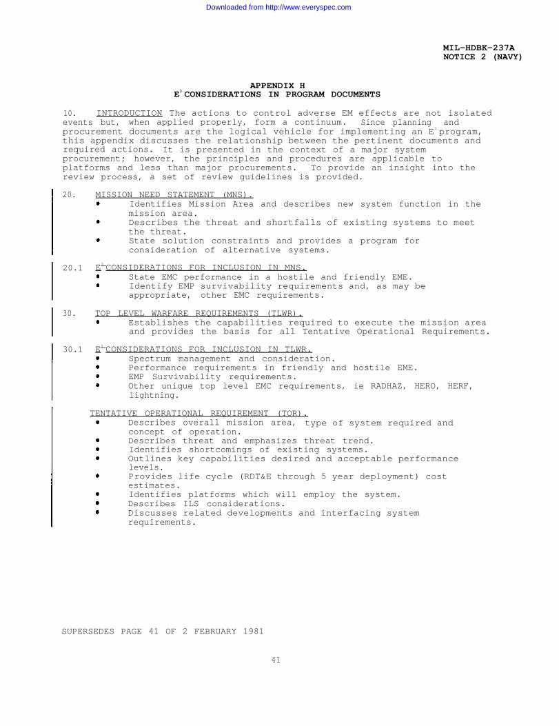
10. INTRODUCTION The actions to control adverse EM effects are not isolatedevents but, when applied properly, form a continuum. Since planning andprocurement documents are the logical vehicle for implementing an E3 program,this appendix discusses the relationship between the pertinent documents andrequired actions. It is presented in the context of a major systemprocurement; however, the principles and procedures are applicable toplatforms and less than major procurements. To provide an insight into thereview process, a set of review guidelines is provided.
20.
20.1
30.
30.1
MISSION NEED STATEMENT (MNS).Identifies Mission Area and describes new system function in themission area.Describes the threat and shortfalls of existing systems to meetthe threat.State solution constraints and provides a program forconsideration of alternative systems.
E3 CONSIDERATIONS FOR INCLUSION IN MNS.State EMC performance in a hostile and friendly EME.Identify EMP survivability requirements and, as may beappropriate, other EMC requirements.
TOP LEVEL WARFARE REQUIREMENTS (TLWR).Establishes the capabilities required to execute the mission areaand provides the basis for all Tentative Operational Requirements.
E3 CONSIDERATIONS FOR INCLUSION IN TLWR.Spectrum management and consideration.Performance requirements in friendly and hostile EME.EMP Survivability requirements.Other unique top level EMC requirements, ie RADHAZ, HERO, HERF,lightning.
TENTATIVE OPERATIONAL REQUIREMENT (TOR).Describes overall mission area, type of system required andconcept of operation.Describes threat and emphasizes threat trend.Identifies shortcomings of existing systems.Outlines key capabilities desired and acceptable performancelevels.Provides life cycle (RDT&E through 5 year deployment) costestimates.Identifies platforms which will employ the system.Describes ILS considerations.Discusses related developments and interfacing systemrequirements.
SUPERSEDES PAGE 41 OF 2 FEBRUARY 1981
41
Downloaded from http://www.everyspec.com
MIL–HDBK-237ANOTICE 2 (NAVY)APPENDIX H
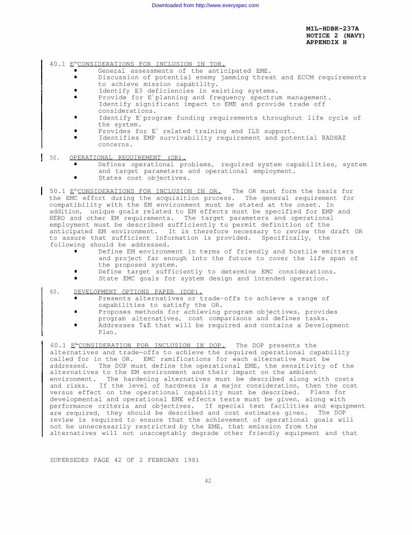
40.1 E3 CONSIDERATIONS FOR INCLUSION IN TOR.General assessments of the anticipated EME.Discussion of potential enemy jamming threat and ECCM requirementsto achieve mission capability.Identify E3 deficiencies in existing systems.Provide for E3 planning and frequency spectrum management.Identify significant impact to EME and provide trade offconsiderations.Identify E3 program funding requirements throughout life cycle ofthe system.Provides for E3 related training and ILS support.Identifies EMP survivability requirement and potential RADHAZconcerns.
50. OPERATIONAL REQUIREMENT (OR).Defines operational problems, required system capabilities, systemand target parameters and operational employment.States cost objectives.
50.1 E3 CONSIDERATIONS FOR INCLUSION IN OR. The OR must form the basis forthe EMC effort during the acquisition process. The general requirement forcompatibility with the EM environment must be stated at the onset. Inaddition, unique goals related to EM effects must be specified for EMP andHERO and other EM requirements. The target parameters and operationalemployment must be described sufficiently to permit definition of theanticipated EM environment. It is therefore necessary to review the draft ORto assure that sufficient information is provided. Specifically, thefollowing should be addressed.
Define EM environment in terms of friendly and hostile emittersand project far enough into the future to cover the life span ofthe proposed system.Define target sufficiently to determine EMC considerations.State EMC goals for system design and intended operation.
60. DEVELOPMENT OPTIONS PAPER (DOP).Presents alternatives or trade-offs to achieve a range ofcapabilities to satisfy the OR.Proposes methods for achieving program objectives, providesprogram alternatives, cost comparisons and defines tasks.Addresses T&E that will be required and contains a DevelopmentPlan.
60.1 E3 CONSIDERATION FOR INCLUSION IN DOP. The DOP presents thealternatives and trade-offs to achieve the required operational capabilitycalled for in the OR. EMC ramifications for each alternative must beaddressed. The DOP must define the operational EME, the sensitivity of thealternatives to the EM environment and their impact on the ambientenvironment. The hardening alternatives must be described along with costsand risks. If the level of hardness is a major consideration, then the costversus effect on the operational capability must be described. Plans fordevelopmental and operational EME effects tests must be given, along withperformance criteria and objectives. If special test facilities and equipmentare required, they should be described and cost estimates given. The DOPreview is required to ensure that the achievement of operational goals willnot be unnecessarily restricted by the EME, that emission from thealternatives will not unacceptably degrade other friendly equipment and that
SUPERSEDES PAGE 42 OF 2 FEBRUARY 1981
42
Downloaded from http://www.everyspec.com
MIL-HDBK-237ANOTICE 2 (NAVY)APPENDIX H
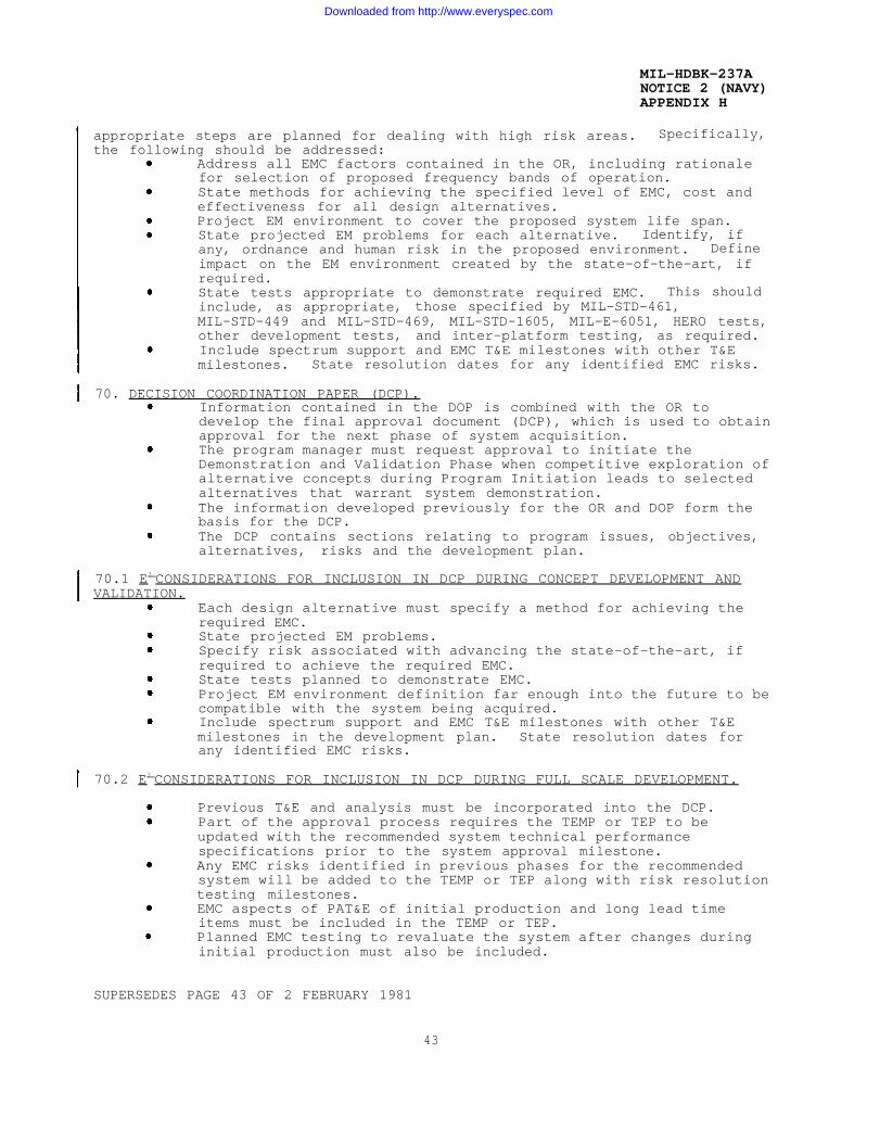
appropriate steps are planned for dealing with high risk areas. Specifically,the following should be addressed:
Address all EMC factors contained in the OR, including rationalefor selection of proposed frequency bands of operation.State methods for achieving the specified level of EMC, cost andeffectiveness for all design alternatives.Project EM environment to cover the proposed system life span.State projected EM problems for each alternative. Identify, ifany, ordnance and human risk in the proposed environment. Defineimpact on the EM environment created by the state-of-the-art, ifrequired.State tests appropriate to demonstrate required EMC. This shouldinclude, as appropriate, those specified by MIL-STD-461,MIL-STD-449 and MIL-STD-469, MIL-STD-1605, MIL-E-6051, HERO tests,other development tests, and inter-platform testing, as required.Include spectrum support and EMC T&E milestones with other T&Emilestones. State resolution dates for any identified EMC risks.
70. DECISION COORDINATION PAPER (DCP).Information contained in the DOP is combined with the OR todevelop the final approval document (DCP), which is used to obtainapproval for the next phase of system acquisition.The program manager must request approval to initiate theDemonstration and Validation Phase when competitive exploration ofalternative concepts during Program Initiation leads to selectedalternatives that warrant system demonstration.The information developed previously for the OR and DOP form thebasis for the DCP.The DCP contains sections relating to program issues, objectives,alternatives, risks and the development plan.
70.1 E3 CONSIDERATIONS FOR INCLUSION IN DCP DURING CONCEPT DEVELOPMENT ANDVALIDATION.
Each design alternative must specify a method for achieving therequired EMC.State projected EM problems.Specify risk associated with advancing the state-of-the-art, ifrequired to achieve the required EMC.State tests planned to demonstrate EMC.Project EM environment definition far enough into the future to becompatible with the system being acquired.Include spectrum support and EMC T&E milestones with other T&Emilestones in the development plan. State resolution dates forany identified EMC risks.
70.2 E3 CONSIDERATIONS FOR INCLUSION IN DCP DURING FULL SCALE DEVELOPMENT.
Previous T&E and analysis must be incorporated into the DCP.Part of the approval process requires the TEMP or TEP to beupdated with the recommended system technical performancespecifications prior to the system approval milestone.Any EMC risks identified in previous phases for the recommendedsystem will be added to the TEMP or TEP along with risk resolutiontesting milestones.EMC aspects of PAT&E of initial production and long lead timeitems must be included in the TEMP or TEP.Planned EMC testing to revaluate the system after changes duringinitial production must also be included.
SUPERSEDES PAGE 43 OF 2 FEBRUARY 1981
43
Downloaded from http://www.everyspec.com
MIL-HDBK-237ANOTICE 2 (NAVY)APPENDIX H
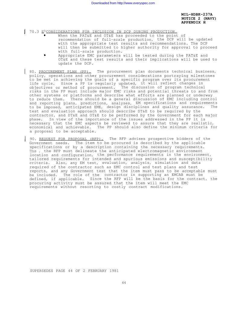
70.3 E3 CONSIDERATIONS FOR INCLUSION IN DCP DURING PRODUCTION.When the PAT&E and OT&E has proceeded to the point ofrecommendation of full-scale production, the DCP will be updatedwith the appropriate test results and recommendations. The DCPwill then be submitted to higher authority for approval to proceedwith full-scale production.Appropriate EMC parameters will be tested during the PAT&E andOT&E and these test results and their implications will be used toupdate the DCP.
80. PROCUREMENT PLAN (PP). The procurement plan documents technical business,policy, operations and other procurement considerations portraying milestonesto be met in achieving the goals of a specific program over its procurementlife cycle. Since a PP is regularly updated, it will reflect changes inobjectives or method of procurement. The discussion of program technicalrisks in the PP must include major EMC risks and potential threats to and fromother systems or platforms and describe what efforts are planned or underwayto reduce them. There should be a general discussion of EMC including controland reporting plans, predictions, analyses, EM specifications and requirementsto be imposed, anticipated EME, design disciplines and quality assurance. Thetest and evaluation approach should describe DT&E to be required by thecontractor, and DT&E and OT&E to be performed by the Government for each majorphase. In view of the importance of the issues addressed in the PP it isnecessary that the EMC aspects be reviewed to assure that they are realistic,economical and achievable. The PP should also define the minimum criteria fora proposal to be acceptable.
90. REQUEST FOR PROPOSAL (RFP). The RFP advises prospective bidders of theGovernment needs. The item to be procured is described by the applicablespecifications or by a description containing the necessary requirements.Thus , the RFP must delineate the anticipated electromagnetic environmentlocation and configuration, the performance requirements in the environment,tailored requirements for intended and spurious emissions and susceptibilitycriteria. Also, any EM test, evaluation, analysis, simulation and datarequired of the contractor such as EMC control and test plans and testreports, and any Government test that the item must pass to be acceptable mustbe included. The role of the contractor in supporting an EMCAB must bedefined, if applicable. Since the RFP will be the basis for the contract, theprocuring activity must be assured that the item will meet the EMCrequirements without resorting to costly contract modifications.
SUPERSEDES PAGE 44 OF 2 FEBRUARY 1981
44
Downloaded from http://www.everyspec.com

MIL-HDBK-237ANOTICE 2 (NAVY)APPENDIX M
APPENDIX MAPPLICATION GUIDE FOR NAVAIR ACQUISITIONS
NAVAIR program managers should refer to NAVAIRINST 2410.1, which definesNAVAIR policy for establishing an effective EMC program throughout the lifecycle of platforms, systems and equipment.
SUPERSEDES PAGE 117 OF 16 JUNE 1986
117
Downloaded from http://www.everyspec.com

MIL-HDBK-237ANOTICE 2 (NAVY)APPENDIX M
THIS PAGE INTENTIONALLYLEFT BLANK
118
Downloaded from http://www.everyspec.com
MIL-HDBK-237ANOTICE 2 (NAVY)APPENDIX N
APPENDIX NWARFARE SYSTEMS E3 CONTROL STRATEGY
10. INTRODUCTION. The Warfare Systems E3 Control Strategy (WSECS) isdescribed in this appendix to provide the PARMs (Participating Managers),Program Managers and other acquisition personnel with an overview of the E3
acquisition methodology currently employed by NAVSEA and SPAWAR. Thismethodology is not intended to supplant the processes described in detail inAppendices J, K & L. It is to be utilized in conjunction with these methodsso that E3 is addressed at the early conceptional stages of acquisition.WSECS is not unlike the AECS described in Appendix L in that it applies a gatecontrol technique to process through the acquisition stages. WSECS isdirected toward achieving EMC through the issuance of Control InterfaceDrawings. These drawings identify and characterize the intentional signalsand allowable degradation.
10.1 APPLICABILITY. The WSECS process is applicable to all warfare systemsacquisitions by the Navy. Implementation of this process provides positive E3
control of the acquisition by establishing prerequisites which must be met ateach phase of the life-cycle.
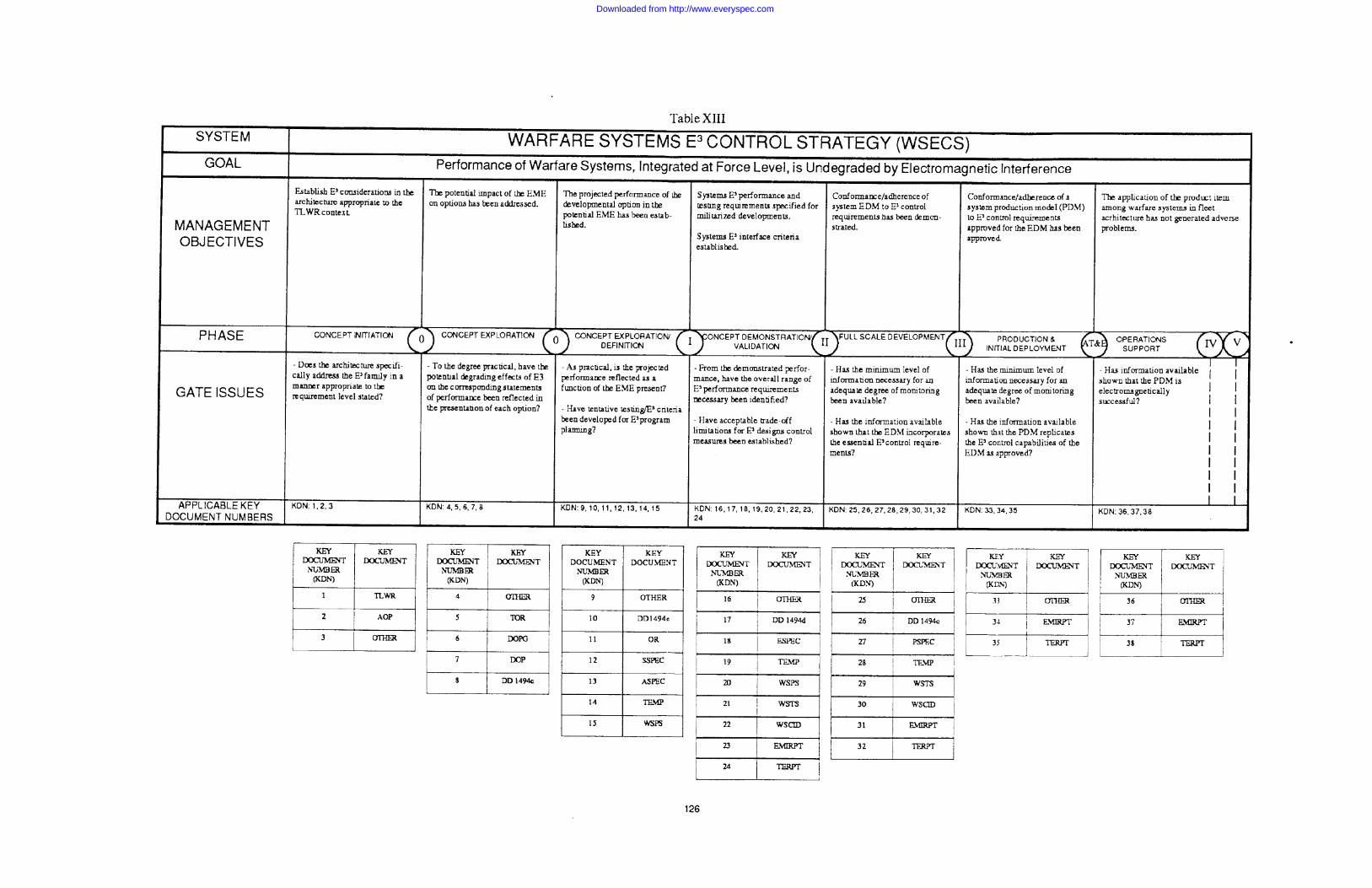
10.2 ELEMENTS OF THE WSECS. Table XIII is a fold-out chart depicting theWSECS. A detailed explanation of the process is contained in the textproceeding the chart. The basic elements of WSECS are:
Establish the performance envelope: Define at the conceptinitiation phase the degree of mission capability required and theelectromagnetic environment in which the system will operate.Define and control all interfaces between warfare systemselements: Issue control interface drawings defining eachinterface of the warfare systems in terms of intentional signal,conducted emissions and conducted susceptibility.Verify compliance: Establish through performance specifications,installation control drawings and test and evaluation requirementsthat E3 compliance has been met.
20. WSECS METHOD. The WSECS applies a positive-control methodology ofgating for E3 control. The process for identification, refinement, andapproval of warfare systems requirements and the subsequent research,development, and acquisition process are gated in a time-phased basiscorresponding to the major decision points during the acquisition life-cycle.Each requirement and subsequent action becomes a part of a continuousevaluation to monitor the extent and adequacy of the E3 control effort. WSECSprovides one or more objectives applicable to each specific phase of thelife-cycle and provides for documentation evaluating the achievement of theobjectives. As a result of this process, at each decision point during thelife-cycle WSECS is ready to present an E3 position concerning an item and themerits of permitting the acquisition to proceed.
30. WARFARE SYSTEMS E3 CONTROL STRATEGY (WSECS). OPNAVINST 5000.42C “RDT&EAcquisition procedures” establishes phases, milestones and threshold criteriafor Navy acquisitions. The WSECS method is an adaptation of this requirementwhich provides E3 control requirements at the acquisition initiation andestablishes definitive requirements at each warfare systems interface. Thiscontrol is achieved by requiring that E3 related key documentation exists ateach phase of the life-cycle. This key documentation provides the basis fordetermining the E3 impact, problems to be resolved, problem resolution, andverification of the effectiveness of E3 controls.
119
Downloaded from http://www.everyspec.com
MIL-HDBK-237ANOTICE 2 (NAVY)APPENDIX N
30.1 KEY DOCUMENTS. For the purpose of WSECS it is unimportant thatinformation be supplied by any particular document, only that it becomesavailable on a timely basis in a suitable form. In the development of WSECS asurvey of normally available or required documentation resulted in theidentification of the key documents presented in Table XIII. Many of theseare E3 documents, which predated the formulation of WSECS, and have beensubjected to formal document reviews. Others are required as part of theacquisition cycles and contain E3 information needed for the WSECS decisionmaking process. It is important to note that WSECS reviews of keydocumentation is for the purpose of extracting desired E3 information and doesnot concern the form or format of the document.
30.2 ISSUES. The identification and resolution of WSECS issues must be aniterative process since each phase of acquisition dictates a new set ofproblems and concerns. In the concept initiation phase, it may suffice tobroadly describe the intended operational EME. But as the acquisitionprogresses, the issues must be more definitive and the resolution bestructured into procurement documentation and test and evaluation plans. Itis by this method that potential E3 problems are highlighted and performancedegradation of the warfare system and its interface system is avoided. Theissues of each phase of acquisition are discussed in more detail in thisappendix as related to the phases of acquisition.
30.3 GATE CLOSURE. When it is apparent from available information that thedirection of the requirement or project does not support the resolution ofcritical E3 issues, the WSECS process denies opening the gate for the nextphase of procurement until satisfactory resolution by the project office isachieved. Should resolution not be forth-coming, it is inherent in the WSECSprocess to formulate the issues for a higher level of authority to review forresolution.
40.0 WSECS PHASES
40.1 THE CONCEPT INITIATION (CI) PHASE. Prepared by the Warfare RequirementsBoard (WRB) at the OPNAV level, TLWRS will ultimately cover each of the fiveWarfare Mission Areas in iterative, dynamic documents. The advent of a new orrevised version of each TLWR (KDN-1) signals the initiation of the RP cycle.When received by SPAWAR, a TLWR is reviewed and assessed with regard to thecurrent architecture, which serves as a baseline and a guide. Thearchitecture directs the search for requirement solutions in approved andpreferred technological fields and dictates ranges and limits of capabilitieson and among platforms. There is a bilateral relationship between a TLWR andthe architecture, and, in the second part, the architecture is itselfreevaluated. In this action, the trends noted in recent TLWRS and the adventof new technologies are evaluated and appropriately factored intoarchitectural revisions. The E3 cognizant office provides the Warfare SystemsArchitect (WSA) with technical support in both of these evaluations, providingreview comments on the TLWR for the Architectural Options (AO) paper (KDN-2)and on the architecture itself, as appropriate. The WSA prepares the actualresponse to the OPNAV WRB. From the mission viewpoint, the TLWR documentaddresses only capability concepts, i.e., requirements as ideas. Theprincipal E3 considerations that have potential as suitable input are thoseconcerning use of the spectrum and frequency management. The nature of theTLWR may suggest additional areas of interest.
120
Downloaded from http://www.everyspec.com

MIL-HDBK-237ANOTICE 2 (NAVY)APPENDIX N
40.2 THE CONCEPT EXPLORATION (CE) PHASE. On the basis of the approved TLWRsand the architecture adopted, the WRB prepares and issues TORS. Multiple TORS(KDN-5) may result from any particular TLWR, and various TORS, rather thanhaving equal status, may share hierarchical relationships among themselves.TORS are general statements of need and carry a demand to propose alternatesolutions. The TORS, as OPNAV documents, are reviewed for information andunderstanding rather than with criticism. The review serves to determine thenecessity for, and the character of the supporting guidance that it may benecessary to provide with a TOR on its way to the cognizant systems command.When generated, the guidance takes the form of a KD described as DevelopmentOption Paper (DOP) Guidance, KDN-6. While the OPNAVINST 5000.42 seriesprovides for E3 control guidance (as EMC guidance) in TORS, the perception ofthe guidance may vary widely. The document prepared by the systems command inresponse to a TOR is the DOP, KDN-7. The DOP is the first document which mayplace the Warfare System community into an adversarial role with a systemscommand project office. As with any option in which electromagnetic (EM)energy plays a significant part, it is necessary for the DOP to addressappropriate E3 control considerations, particularly if the effects are notrelatively constant, uniform considerations for all options. Depending uponthe nature and degree of the EMC deficiency, alternative approaches can beemployed:
a. The DOP may be rejected and returned for revision to the systemscommand in order to overcome the E3 deficiencies noted. Since this methodadds further delay for a document responding to a TOR that is probably 12 to18 months old already, it should be used only in the most unsatisfactorycases.
b. The DOP may be endorsed and forwarded to CNO with comments coveringthe E3 deficiencies, and with a copy to the systems command. The SYSCOM canthen provide supplementary data addressing the endorsement at an early date.
The last KD for the CE Phase is the DD Form 1494 application for a frequencyallocation, Stage 1 (Conceptual), and is designated KDN-8. Each DOPalternative which proposes to transmit or receive EM energy needs anapplication, except that the same type of transmission or reception formultiple alternatives may be covered by a single application. No applicationis necessary if there is no transmission or reception of EM energy. There is,of course, no actual hardware at this stage, and KDN-8 serves as a “heads up”alerting mechanism. More specifically, the KDN-8 is a pre-project inquiry toelicit potential, but unsuspected, spectrum utilization problems. Theapplication should be prepared and forwarded, as soon as possible, for anyalternative in a draft DOP that requires use of the spectrum. When the KDN-8DD Form 1494 is required, no DOP should be forwarded to CNO until theattendant KDN-8 has been processed and forwarded for approval. A DOPproposing alternatives whose spectrum utilization would suggest a seriouspotential for interference, may be held until necessary KDN-8 applications arereceived for processing.
Nominally, the CE phase ends with the transition of Milestone O. The WSECSand RD&A processes are not, however, locked to one-another at this time, andthe WSECS gate may open ahead of actual Milestone O approval.
40.3 THE CONCEPT EXPLORATION/DEFINITION (CED) PHASE.a. The CED Phase has another DD Form 1494 application requirement
(KDN-10), for a Stage #2 (Experimental) frequency allocation. This allocationserves to confirm and expand upon the earlier Conceptual request. It coversthe Advanced Development Model (ADM) hardware which is to be built and testedduring Phase I (Concept Demonstration/Validation) of the RD&A process. Where
121
Downloaded from http://www.everyspec.com
MIL-HDBK-237ANOTICE 2 (NAVY)APPENDIX N
there is no novelty in the spectrum utilization posed in the application, theStage #1 (conceptual) type, KDN-8, may be combined with the Stage #2, KDN-10.Although WSECS calls for this application to be submitted prior to MilestoneI, a prudent Project Manager (PM) will submit it even earlier if possible.Until the appropriate frequency allocation application has received CNOapproval, under OPNAVINST 2400.20E, funds may not be obligated on a contractfor an ADM, even though Milestone I approval may have been granted to initiatea project. DD Form 1494 applications may take in excess of six months forapproval.
b. The WRB, after reviewing a DOP submission and arriving at afavorable decision, issues an Operational Requirement (OR) based on preferredoption(s) . This is KDN-11 and is tantamount to the issuance of projectapproval for small items in Acquisition Categories (ACATs) III & IV. The ORis a refined presentation of the favored option, is established as a KD forits directive value and forms the basis of the Navy Decision CoordinatingPaper (NDCP) to be used to approve the new project formally. The review ofthe OR also forms the basis for the Warfare Systems Performance Specification(WSPS). The output of the review should be placed in the form of DesignGuidance for the WSPS.
c. Two additional KDs are used during the CED Phases: the SystemsSpecifications (KDN-12) and the Item Specifications (KDN-13).
(1) KDN-12, when available, sets the level of E control directionin a system project. This may be readily apparent, e.g., with anaircraft item as the system, where the requirements of MIL-E-6051 areinvoked. In other platform types for which there is no system-level E3
standard control as yet, the task of E3 control assessment andallocation may require extended reading. For proper system E3 controlto result, downward direction and allocation of requirements must beimplemented from the systems level, establishing interfaces, specifyingisolation, filtering, levels, EM practices, etc. A system may not belimited to a single platform; while this may complicate the project, thesystem considerations stated earlier still apply. Regardless of theintra- or inter-platform nature of the system, the basic requirementsstated in the CED Phase form the foundation necessary for successful E3
control in later development phases. E3 control measures that arenecessary only in lower indentures, but fundamental to system E3 controleffectiveness, must be directed by the system specification.
(2) Where the project is of lesser scope than that of an entireplatform and the project item is normally considered at the unit, group,or set level, an Item Specification is prepared. The Item Specificationis the ADM Specification; i.e., it is the specification that will beused during Phase I on a contract for the ADM hardware. To facilitatecontract award, following Milestone I approval, the specification musthave been prepared, coordinated, revised, and approved at an earliertime during the CED Phase. This provides an early opportunity for WSECSto determine how fully the project will follow E3 control guidance givenearlier. Because the ADM is not a MIL-specified item, however, it isnot reasonable to expect or demand a full range of MIL-STD-461requirements and MIL-STD-462 tests for this technology-demonstrationhardware. Should the ADM represent integration of previously developedhardware, in whole or in part, the use of which will remain unchanged inthe Engineering Development Model (EDM), a requirement in thespecification, to use components qualified to MIL-STD-461, would beessential.
122
Downloaded from http://www.everyspec.com

MIL-HDBK-237ANOTICE 2 (NAVY)APPENDIX N
d. Where hierarchical requirements exists, specifications willsimilarly exist on multiple levels. For this reason, KDN-12 is established inTable XIII, as a separate item from KDN-13. In the event that two levelsexist simultaneously for a given requirement, the lowest will always beidentified as KDN-13 and each of the others will be identified as KDN-12.
e. The Test & Evaluation Master Plan (TEMP), as KDN-14 in its firstiteration, is required for the Milestone I review. The TEMP is a particularlysignificant document prepared by the project office, which establishes thecriteria as well as extent and schedule for project operational evaluation.For review considerations, the TEMP should state E3 control evaluationcriteria for operational effectiveness and operational suitability.
f. KDN-15 is assigned to the Warfare Systems Performance Specification(WSPS). The WSPS is based on the evaluation of the OR (KDN-11). From each ofseveral major technical disciplines of which E3 is a representative member,input in the form of Design Guidance is supplied. The input is based on theparochial interest of the discipline. The WSPS provides the broad systemsynthesis of these guidance inputs.
40.4 THE CONCEPT DEMONSTRATION/VALIDATION (CDV) PHASE. Most active of allphases for WSECS, CDV is a particularly important time for the WarfareSystems Engineer (WSE). For each project formally begun by OR, the WSE mustat this time prepare, coordinate, negotiate, revise, and issue two more majordocuments as in follow-on to the WSPS.
a. The Warfare Systems Test Specification (WSTS) and the WarfareSystems Control Interface Drawing (WSCID) are KDNs 21 and 22 respectively.Using these documents, the WSE applies and disseminates additional WarfareSystem Architecture and Engineering requirements. For the WSCID, the minorsupporting documents, Notice of Change (NOC) and Proposed NOC (PNOC), servethe purpose indicated by their names. (This is actually a single document;the PNOC becomes the NOC upon approval.) The WSTS, KDN-21, has no formalinstructions issued for its preparation as yet. It may be anticipated,however, that it will specify the verification requirements and methods forcorresponding WSPS requirements. The first generation of WSCID documents(KDN-22), in complying with SPAWARINST 9000.1, appear to be addressing onlyhardwire conducting interfaces. For this form of porting, the CE- and CS-requirements of MIL-STD-461 are appropriate limits for all undesired signal(noise) energy present. A PNOC is evaluated with the WSCID to which it isapplicable; the acceptability of the PNOC is commented accordingly. Aresulting NOC becomes part of the WSCID affected. The WSPS precursor to theabove two KDs is ordinarily issued prior to Milestone I, i.e., before the CDVPhase. Should it have been delayed into CDV, KDN-20 is assigned, and itsreview is performed as needed. The Design Guidance for the WSPS would havebeen developed during the OR review in the CED Phase.
b. Three document forms common to the previous phase have counterparttypes during the CDV phase. A DD Form 1494 application for the Stage #3(Developmental) Frequency Allocation is KDN-17. This KD is to be receivedprior to Milestone II, and its approval must be secured before the EDMcontract may be awarded in Phase II. The Full Scale Development (FSD)Specification (KDN-18) which will cover the device EDM, is written during theCDV phase prior to, and in preparation for, Milestone II. The FSDSpecification is of particular importance since requirements seen necessaryduring D&V, incorporated and proven during test and evaluation (T&E), andlater given approval for full-rate production (AFP), are those that willcontinue into the Production and Initial Deployment Phase. The EDM is theproper candidate for full MIL-STD-461 qualification. Finally, the seconditeration of the TEMP is designated as KDN-19, and is required for Milestone
123
Downloaded from http://www.everyspec.com

MIL-HDBK-237ANOTICE 2 (NAVY)APPENDIX N
II also. E3 control criteria should be updated based on the projectexperience of the CDV phase and as appropriate for KDNs 20, 21, and 22 and aspreviously described.
Finally CDV phase KDs include two report types: KDN-23 covers anyEMI, EMC, or IMI test reports for any standards (MIL-STD-461, MIL-STD-469,etc.), and KDN-24 covers T&E reports whether for DT-I or OT-I. Unlike KDN-16through 22, however, KDN-23 and -24 are processed to support a new role forSPAWAR. In the new role, SPAWAR acts for E3 only as a monitor. Informationobtained from these KDs is channeled into project evaluations, but nodirective action is taken with regard to the project or other offices. Thislimited monitoring role, begun during CDV, will expand during FSD to almost100% monitoring.
40.5 THE FULL SCALE DEVELOPMENT (FSD) PHASE). With the approval at MilestoneII, the item moves into the FSD Phase. As indicated in 40.4, the SPAWAR roleshifts in FSD from that of advocate and arbiter for Warfare SystemsArchitecture & Engineering, into a passive role which monitors compliance bythe project office. A residual directive role remains for E3 in FSD in regardto two of the KD types:
a. As Milestone III is approached, the final iteration of the TEMP,KDN-28, is prepared, offering one last opportunity to improve or correct theE3 control criteria for T&E.
b. The final frequency allocation application is to be made prior tothe Milestone III review. This is KDN-26, the Stage #4 (operational) request.
c. Lastly, three additional documents are monitored to determine thedegree to which the project office is adhering to guidance. These are theItem Specifications (KDN-27) for Production, Test Report (KDN-31) which coversEMC/EMI/IMI reports, surveys, incidents, etc. (MIL-STD-461, -462, -469,-1605, etc.), and the DT-II and OT-II test reports, both grouped together asKDN-32. These sources are reviewed in support of the command monitoringfunctional responsibility only. No routine report or evaluation is made toother offices.
40.6 THE PRODUCTION & INITIAL DEPLOYMENT (PID) PHASE. The PID Phase startswhen a project has been approved for full rate production (AFP). Thisauthorization occurs concurrently with Milestone III (at times with IIIB)approval. The role of SPAWAR continues to be that of monitor, observingprojects to assess the degree of compliance with previous guidance. Only twoKDs are listed for this phase, EMI Test Reports, KDN-34, and OT-II or III TestReports, KDN-35, although other sources may be found useful, however. As inthe previous phase (FSD), no routine evaluation reports are made. WSECSestablishes its own milestone in the absence of a formal one in the RD&Acycle. This is the Production Acceptance Test & Evaluation (PAT&E) for theproduction contract, the PAT&E reports of which are KDN-35.
40.7 THE OPERATIONS SUPPORT (OPS) PHASE. As the item becomes a commoncapability in the resources of the Fleet units making up the force, nospecific documents are designated to be monitored; KDN-37, however~ isassigned to cover any type of EMI or EMC deficiency report. Documents ofopportunity which may provide information regarding an EMI problem includemajor Fleet exercise reports, casualty reports (CASREPS), or any otherdocuments which address the existence of an EMI condition. Additional OT-IIIreports are covered by KDN-38. The OPS Phase has one unique feature: thegate condition for any project is routinely regarded as open. Should an EMIcondition emerge, the gate then closes until the unsatisfactory condition isremoved. In theory, multiple EMI problems might occur within a particular
124
Downloaded from http://www.everyspec.com

MIL-HDBK-237ANOTICE 2 (NAVY)APPENDIX N
force. Should this be the case, several documents would report conditionspertaining to these several problems. The OPS Phase Gate would remain closeduntil each of the problems was resolved separately.
50.0 USING WSECS IN THE NON-CLASSIC REAL WORLD. The WSECS process ispresented in 40.1 through 40.7, as it might be manifested ideally by thevarious KDs. The series of KDs from Table XIII emerge in time sequence toprovide appropriate information for decisions. Do not be surprised, however,if the revelation of information is less orderly in the real world.Nevertheless, keep it clearly in mind that the degree of issue resolutionremains the fundamental product to be sought by each KD evaluation.
125
Downloaded from http://www.everyspec.com
Downloaded from http://www.everyspec.com