Embed Size (px)
Citation preview

U.P.B. Sci. Bull., Series C, Vol. 83, Iss. 3, 2021 ISSN 2286-3540
MIGRATION TO MODERN DISTRIBUTED CONTROL
SYSTEMS IN ELECTRIC POWER SUBSTATIONS:
INTEGRATION VS. REPLACEMENT
Danut Adrian POSTOVEI1, Constantin BULAC2
This article discusses two migration strategies to modern Distribution
Control Systems, one approach is to save as much as possible the past investment by
integrating and upgrading the old automation equipment and the software, and the
other is to deliver a completely new solution with up-to-date technology. The
purpose of this paper is to illustrate the gain and the drawback when choosing one
strategy or the other. Other goal is to illustrate the needs of migration to fully IEC
61850 standard as path for transition towards digital substations.
Keywords: DCS, SCADA, BCU, IED, RTU, IEC61850, migration.
Abbreviations DCS Distributed Control System
SCADA Supervisory Control and Data Acquisition
IED Intelligent Electronic Device
GOOSE Generic Object-Oriented Substation Events
TCP/IP Transmission Control Protocol/Internet Protocol
BCU Bay Controller Unit
RTU Remote Terminal Unit
HMI Human Machine Interface
PRP Parallel Redundancy Protocol
RSTP Rapid Spanning Tree Protocol
NCC National Control Center
LAN Local Area Network
FE Front End (SCADA Master Unit)
EWS Engineering Working Station
I/O Input / Output
1. Introduction
The modern DCSs evolved into a flexible and scalable automation
solutions which make them mandatory in the actual competitive energy business
1 PhD student, Dept. of Power Engineering Systems, University POLITEHNICA of Bucharest,
Romania, e-mail: [email protected]. 2 Prof., Dept. of Power Engineering Systems, University POLITEHNICA of Bucharest, Romania,
e-mail: [email protected].
256 Danut Adrian Postovei, Constantin Bulac
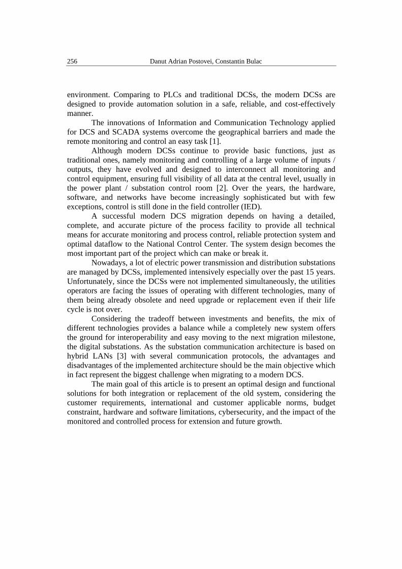
environment. Comparing to PLCs and traditional DCSs, the modern DCSs are
designed to provide automation solution in a safe, reliable, and cost-effectively
manner.
The innovations of Information and Communication Technology applied
for DCS and SCADA systems overcome the geographical barriers and made the
remote monitoring and control an easy task [1].
Although modern DCSs continue to provide basic functions, just as
traditional ones, namely monitoring and controlling of a large volume of inputs /
outputs, they have evolved and designed to interconnect all monitoring and
control equipment, ensuring full visibility of all data at the central level, usually in
the power plant / substation control room [2]. Over the years, the hardware,
software, and networks have become increasingly sophisticated but with few
exceptions, control is still done in the field controller (IED).
A successful modern DCS migration depends on having a detailed,
complete, and accurate picture of the process facility to provide all technical
means for accurate monitoring and process control, reliable protection system and
optimal dataflow to the National Control Center. The system design becomes the
most important part of the project which can make or break it.
Nowadays, a lot of electric power transmission and distribution substations
are managed by DCSs, implemented intensively especially over the past 15 years.
Unfortunately, since the DCSs were not implemented simultaneously, the utilities
operators are facing the issues of operating with different technologies, many of
them being already obsolete and need upgrade or replacement even if their life
cycle is not over.
Considering the tradeoff between investments and benefits, the mix of
different technologies provides a balance while a completely new system offers
the ground for interoperability and easy moving to the next migration milestone,
the digital substations. As the substation communication architecture is based on
hybrid LANs [3] with several communication protocols, the advantages and
disadvantages of the implemented architecture should be the main objective which
in fact represent the biggest challenge when migrating to a modern DCS.
The main goal of this article is to present an optimal design and functional
solutions for both integration or replacement of the old system, considering the
customer requirements, international and customer applicable norms, budget
constraint, hardware and software limitations, cybersecurity, and the impact of the
monitored and controlled process for extension and future growth.

Migration to modern Distributed Control Systems in electric power substations: integration… 257
2. Methods and Materials
2.1. DCS vs. SCADA
The best automation solution to monitor and control a process, specifically
an electrical power substation is a DCS. The evolution and complexity of DCSs
has greatly diminished the difference from a SCADA system. However, some
features differentiate them, as shown in the Table 1. Table 1
Comparison between DCS and SCADA systems
DCS SCADA
Manage operations in a single location, plant,
or substation.
Manage applications that are spread across a
wide geographical location.
Advanced monitoring and control capabilities
of the single location, plant, or substation.
Interconnects multiple RTUs, DCSs or simple
PLC controllers.
It is a process state driven, oriented towards
the technological process, receive, and send
data to the distributed process controllers.
It is an event driven system, oriented towards
data collection, and its central station usually
"stands" over simple RTUs or complex DCS.
Uses a network to interconnect sensors,
controllers, and actuators.
Cannot perform advanced process control
techniques by its own. Supervision of the
process. mainly of changing primary equipment
position and set points of automations.
It is more integrated in the process and can
perform high-end automation tasks.
It is bigger than a DCS and more flexible.
Currently, according to the ANRE report for 2019, the monitoring and
control at the SCADA central level of the electrical power substations in the
portfolio of the transmission and distribution operators, Transelectrica SA and the
Electrica SA, are presented in Table 2.
Table 2
Current substations integration in SCADA systems (Romania) [4]
Items Transmiss ion Operator
(Transelctr ica)
Distr ibut ion
Operator (Electrica )
Total substations / cells (feeders) 81 / 630 6.500 / 35.000
Total SCADA datapoints > 35.500 > 122.000
SCADA platform e-Terra (AREVA France) SCATEX (Efacec Portugal)
37 x Substations 400 kV 98% ---
40 x Substations 220 kV 95% ---
66/99 x Substation 110 kV 95% 80%
590 x PA/PT (transformer points) --- 6%
Remote Reclosers /Disconnectors --- 530 / 1.070
Primary high voltage equipment 6.500 4.600
Loads (direct consumers) 9 13.954
Switches 4.410 62.022
Shunt reactors / Capacitor banks 17 106
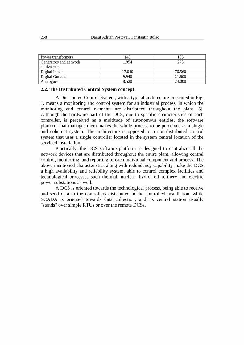
258 Danut Adrian Postovei, Constantin Bulac
Power transformers 149 106
Generators and network
equivalents
1.854 273
Digital Inputs 17.040 76.560
Digital Outputs 9.940 21.800
Analogues 8.520 24.000
2.2. The Distributed Control System concept
A Distributed Control System, with a typical architecture presented in Fig.
1, means a monitoring and control system for an industrial process, in which the
monitoring and control elements are distributed throughout the plant [5].
Although the hardware part of the DCS, due to specific characteristics of each
controller, is perceived as a multitude of autonomous entities, the software
platform that manages them makes the whole process to be perceived as a single
and coherent system. The architecture is opposed to a non-distributed control
system that uses a single controller located in the system central location of the
serviced installation.
Practically, the DCS software platform is designed to centralize all the
network devices that are distributed throughout the entire plant, allowing central
control, monitoring, and reporting of each individual component and process. The
above-mentioned characteristics along with redundancy capability make the DCS
a high availability and reliability system, able to control complex facilities and
technological processes such thermal, nuclear, hydro, oil refinery and electric
power substations as well.
A DCS is oriented towards the technological process, being able to receive
and send data to the controllers distributed in the controlled installation, while
SCADA is oriented towards data collection, and its central station usually
"stands" over simple RTUs or over the remote DCSs.

Migration to modern Distributed Control Systems in electric power substations: integration… 259
Fig. 1.Distributed Control System Architecture (adapted from [5])
As presented in Fig. 1, a DCS consists mainly in three basic components:
Main/Backup Server with the role of a supervisory computers to collect and
centralized the process data and provide the HMI interface, field controllers
(IEDs) with the associated field sensors and control elements and a
communications network.
The modern DCS concept improves system reliability and decreases
installation costs by placing the control functions near the field process but
keeping centralized remote monitoring and supervision features. Taking into
consideration the other characteristics such flexibility and scalability, a modern
DCS can handle various automation processes from a small to a very large one. In
the case of substations retrofitting an optimal solution is represented by an
implementation of a multi-level DCS architecture.
Of course, there is no perfect scenario regarding the integration of an
existing DCS into a new one or to operate separately the two systems. Depending
on the technological differences between the two systems, each situation must be
analyzed separately.
2.3. DCS communication architecture
A DCS availability or network redundancy is directly associated with
overall plant or controlled technological minimal interruption, as an essential
requirement for the continuous monitoring and safe control.

260 Danut Adrian Postovei, Constantin Bulac
Currently, the most common communication architectures for DCSs used
in electric power substations are represented by a mixed combination of “Link
Aggregate" and RSTP, or "Link Aggregate" and PRP [6].
The term "Link Aggregate" refers to how to connect multiple network
links in parallel, to increase the transfer capacity or, more importantly, to see a
DCS ensuring redundancy in case of one communication link failure.
The RSTP protocol prevents the problem of loops in the communications
network by forming a logical tree network that includes all the switches in the
network, thus ensuring that certain network connections are put in a standby state,
so that there is no traffic data through that connection, thus breaking any physical
loop in the network.
The PRP protocol offers uninterrupted communication redundancy, with
an error failure time of 0ms required for high-speed critical functions. The
“sender” uses two independent network interfaces that transmit the same data
simultaneously, and the “receiver” uses the first data packet and rejects the second
one. If only one data packet has been received, the receiver interprets that a fault
has appeared on the other communication channel.
In case of limited budget implementation, RSTP is the right choice being a
protocol supported by most industrial devices. RSTP is not recommended for very
complex DCS architectures and interoperability with proprietary protocols, or in
the situation where the recovery time of communication failure is essential, due to
the network high latency.
PRP can run on two independent networks and therefore can perform hot
swap switching of network devices, regardless of network topology: star, ring or
mixed, performing communication recovery in 0ms (bump less), a function
achieved by continuous monitoring of network devices. This aspect is achieved by
doubling the network interfaces and the copper or fiber optic cable connections,
which leads to a high cost with the implementation of the DCS network.
Devices with only one Ethernet interface (printers, laptops, GPS) can be
connected just to one of the PRP LAN. In PRP architecture the switches must
handle Jumbo-Ethernet frames and the linkage of the two networks could leads to
breakdown of the communication.
The use of the combination of the two standards ensures an N-1
redundancy, having the network return time within a range of seconds.
2.4. Intelligent Electronic Device
The generation, transmission, and distribution of power needs 24/7
monitoring and control to maintain the grid reliable and uninterrupted power
supply. In this respect, the flexibility in integration and interoperability of IEDs

Migration to modern Distributed Control Systems in electric power substations: integration… 261
over RTUs lead to a migration from the classic RTUs to IEDs in all new DCS
implementations.
IEDs (Intelligent Electronic Device) are microprocessor-based equipment
with continuous self-supervision, used in the electric power system for
monitoring, controlling and protection functions. There are many types of IEDs
used in a substation network, such as BCU (Bay Control Units) to monitor and
control of disconnectors and circuit breakers, protection relays to detect faults,
switch off and isolate selectively the protected equipment from the power grid so
that the consequences of the defect are limited as much as possible [7], AVR
(Automatic Voltage Regulator), metering units (MU), power transformer
monitoring (Qualitrol), ATS (Automatic Switch Transfer), etc.
2.5. IEC 61850 communication protocol
Since its first release in 2003, IEC61850 was widely adopted by all the
DCS manufacturers and nowadays all the architectures rely on this standard. It is a
protocol based on Ethernet networking and designed to perform protection
functions, monitoring, control, and metering functions. The IEC61850 standard
provides four types of communication services that allow data exchange between
devices connected to the same network, such as:
- Client–Server based on TCP/IP MMS (Manufacturing Messaging
Specification), connection-oriented protocol. DCS/SCADA systems use MMS
Client/Server communication to perform the monitoring and control functions.
Applications from DCS servers to IEDs, like protection relay or BCU using the
Client/Server services are not time critical. The acceptable latency of
Client/Server communication is in the range of 100-200ms, with the maximum
delivery time of 800ms and a maximum recovery time of 400ms [8]. TCP/IP
mechanisms also care for repeating lost frames and the right ordering in the
receive buffers.
- GOOSE (Generic Object-Oriented Substation Event) protocol, directly
on Layer 2, multicast, repetition mechanism, for the fast transmission of data over
the network. Even if the GOOSE messages have no destination address, by design
they are restricted to stay within a LAN and do pass not pass-through routers to
other LAN [9].
Applications between IEDs like interlocking signals and trip messages use
the GOOSE service based on a connectionless one to many – the multicast
service. Goose service has a maximum delivery time of 8ms and a maximum
recovery time of 4 milliseconds. IEC 61850 standard distinguishes between two
types of reporting: buffered reporting and unbuffered reports. in the first case the
reports are buffered by the server in case a connection to the client is interrupted
and in the second case the Server just "throws" the report to the communications

262 Danut Adrian Postovei, Constantin Bulac
network without knowing if the message get to the required Clients, and if the
communication is down the message will be lost.
- Sampled Values (SV) protocol, directly on Layer 2, multicast, data
stream, for the fast transmission of analogue values over the network. SV has a
maximum delivery time of 2ms and a zero-recovery time (bump less redundancy).
- Basic services like NTP, SNMP, HTML are not time critical. Those
services have a maximum delivery time of 500ms and a recovery time of 300ms.
The GOOSE and SV protocols are used for critical high-speed functions
such as station interlocking, protection tripping and blocking schemes and other
station-related protection devices and control functions [8]. Protection devices are
required to safeguard the expensive power equipment and transmission lines
against overloads and damages [10].
In the analyzed study case presented in Fig. 2, the common language
between IEDs, system servers and Gateways and RTU is represented by
IEC61850 protocol [11].
2.6. IEC 60870–5–104 communication protocol
It is a Master-Slave protocol, which provides a communication profile for
monitoring and control between two automation systems.
The IEC 60870–5–104 specification combines the application layer of IEC
60870-5-101 [12] and the transport functions provided by a TCP/IP (Transmission
Control Protocol/Internet Protocol) [13].
In the architecture presented in Fig. 2, IEC 60870–5–104 protocol is used
to exchange data between Gateway and NCC, where the NCC is the
Master/Controlling station and HV-DCS is the Slave/Controlled station.
Being a multilevel architecture, the HV-DCS Gateway acts as a Master
and MV-DCS RTU as a Slave. It is observed that the Gateway play both role,
Master and Slave. In Fig. 2, HV-DCS under IEC 60870–5–104 is either a
controlling station or a controlled station.
2.7. Ethernet protocol
It is defined by IEEE 802.3. standard and is still the most popular set of
protocols for the Physical and Data Link layers. Ethernet protocol is preferred in
electric power substations for its data transfer quality, high speed, security, and
reliability. Even if Ethernet operate at different speeds and use different types of
media, all the versions are compatible with each other being able to communicate
in the same network through interconnection devices such as bridges, hubs, and
switches.

Migration to modern Distributed Control Systems in electric power substations: integration… 263
2.8. Dual Homing (Dual Link)
It is a network redundancy protocol with recovery time, having two active
links, one is sending and the other one is in hot stand-by, sending link changes if
one link is down. The switch over time is < 5ms. This type of redundancy is
applicable for all industrial computers, such System servers, Gateways, EWS,
HMI and RTU in case of 20 kV network.
This solution also comes with some limitations such supervision of only
directly linked connections and broken connections in the upper or lower network
will be not detected by the device.
3. Key experiments
The present work intends to present some migration aspects, advantages,
disadvantages, and recommendations related to different DCS migration scenarios
for two similar substations, with the same scope of better visibility of the running
process and more connectivity of the substations in the power grid network.
The two migration approaches in this paper are:
a) Integration: is a stepwise migration of the existing DCS into the new one,
even having the possibility of operating in parallel the old and the new
systems.
b) Replacement: remove the existing automation system and replace it with a
completely new DCS.
Fig. 1 Study case laboratory framework

264 Danut Adrian Postovei, Constantin Bulac
As presented in Fig. 2, for both scenarios, the real architectures
implemented in the substations were simplified and reproduced by the authors in
the SCADA Laboratory at University POLITEHNICA of Bucharest / Faculty of
Power Engineering / Power Engineering Systems Department, covering all the
intended experiments such, hybrid LANs, data exchanged between DCS levels,
GOOSE messages, IEC61850 and legacy protocols communication
interoperability, HMI, monitoring, control and data acquisition, protocols
conversions and telecontrol from upper SCADA level.
3.1. Case study 1 – Integration of an existing DCS
Despite of intensive automation and monitoring of substations, the
medium voltage part still has a marginal role comparing to high voltage ones.
In this context exists the first scenario which analyzes the integration
aspects of a an already running DCS for a 20 kV substation, and its integration,
when migrating the entire substation which include 220 kV and 110 kV voltage
levels, to a modern DCS.
Fig. 3. Turnu 20 kV substation-Existing DCS (simplified communication architecture)
As presented in Fig. 3, the study case starts from an existing situation,
respectively a running DCS in Turnu 20 kV substation.
The existing system consists of:
- A proprietary DCS software platform.
- 18 x IEC61850 compatible IEDs, mounted inside 20kV panels;
- 6 x IEC 60870-103 legacy protection relays, mounted in 110kV
transformer bay cabinets;

Migration to modern Distributed Control Systems in electric power substations: integration… 265
- 2 x Modbus devices for each 110/20 kV transformer bay, dedicated for
automation functions such ATCC (Automatic Tap Changer Control) and ATS
(Automatic Transfer Switch);
- One RTU which collect all the data from the process;
- A local HMI and the maintenance laptop.
- Communication infrastructure composed of communication switches
optical fiber, Ethernet copper cable and serial RS485 cables.
The scope of this first study case is to present an optimal architecture
design, data models compatibility, overall system limitations, advantages, and
disadvantages of this migration strategy. When starting from an existing system as
shown in Fig. 2 and need to fulfill the customer demands to integrate the existing
system into the new one and keep both systems running in parallel, to reduce the
present investment and save it the past one, the optimal solution is to design a
multilevel DCS, as presented in Fig. 4.
Fig. 4. Turnu 220/110/20 kV substation (simplified architecture after the migration)
Under those circumstance the design of DCS architecture represents the
big challenge, to reach a reliable communication network while keeping in
operation legacy devices and communication protocols. Practically, a hybrid
communication system, adopting different technologies at the same time [14] was
implemented by the authors, able to connect the upper SCADA level with the new

266 Danut Adrian Postovei, Constantin Bulac
220 kV, 110 kV and the existing 20 kV substations. The result of the migration is
a multilevel DCS architecture, as presented in Fig. 4.
If at the main level the common language between the network equipment
is IEC61850, the exchanged information with the existing system is done through
the IEC 60870-5-104 protocol. Being a Master-Slave protocol, the exchanged data
between two systems must pass through the 20 kV RTU. Since there is only one
RTU, any communication failure of it will separate completely the two systems.
Even if some elements of the existing system network have IEC61850
capabilities and referring to GOOSE messages, they cannot be used by the main
level elements due to the fact that the multilevel system is composed of two
distinct networks, which prevents the exchange of GOOSE messages. To
exchange the needed data between the IEDs from the two networks, the binary
and analog signals must be wired.
Although at first glance the operation of two separate DCSs may suggest
some advantages and cost savings for the owner, following this implementation
the impact of operating with different technologies are highlighted here below:
Advantages: Saving the past investment, familiarity, and continuity with
the old system.
Disadvantages: data accessibility issue from legacy devices, difficulty to
accommodate different technology in the same architecture; serial devices receive
and process only messages sent directly to them, frequent failures; maintenance
and costly protocol convertors, use a separate network to get disturbance
recordings from protection relays; unsupported hardware and software;
Cybersecurity issues when using outdated software such Windows XP/7; limited
the benefits of the newest technology like using the GOOSE which means a
bigger quantity of wired copper cables to ensure the interoperability with the
modern DCS; the integration of the old systems required costly protocol
converters, meaning additional communication delay / latency in the network.
Even though a legacy control system may still work well after 30 years or
even longer doesn’t mean that it is operating efficiently, reliably, safely, or cost-
effectively.
Recommendations: replace the old RTU by a modern System Server to
better carry on the new role of the gateway between the two systems, after the
migration. In case of extreme budget constraint, the RTU can be virtualized
(virtual machine) inside the System Server of the new system; segmentation of the
20 kV communication network in two parts, one dedicated for IEDs 1-18 which
exchange only IEC61850 messages and the second one for the two transformer
bay controllers which convert Modbus and IEC 60870–5–103 legacy protocols to
IEC 61850. For redundancy purpose, the old system must have four Ethernet
switches instead of existing three; connect the IEDs 1-18 to the new system

Migration to modern Distributed Control Systems in electric power substations: integration… 267
network, to benefit of GOOSE messages features and reduce the copper wiring
connection to the new system.
3.2. Case study 2 – Remove and Replace the existing DCS
The context of choosing this approach is represented by a recent real
upgrade of three electric power transmission substations, respectively Raureni,
Arefu and Hasdat 220/110 kV, owned by Transelectrica SA, Romanian
Transmission and System Operator (TSO). Going back in 2008, the initial
supplier was Areva T&D France. After 10 years, in 2018 the owner decided to
upgrade all the above-mentioned substations, but this time the contract was
awarded to a different supplier, respectively Siemens AG Germany. In this
context, Siemens decided to migrate the entire DCS to its own brand and to the
up-to-date technology, instead of upgrading the existing ones. For this study case
Arefu 220/110/20 kV substation implementation was analyzed, like Turnu
220/11/20 kV substation, but the migration strategy was to remove the existing
system and replaced it with IEC61850 devices [15].
The substation DCS architecture was designed based on Ethernet network,
with three levels: Level 0 = Process, Level 1 = Direct Control and Level 3 = Plant
Supervisory. Arefu substation architecture has one main communication ring in
redundant ring topology and several bay LAN segments, where all the IEDs are
connected. IEDs are designed with PRP for the redundancy purpose and high
system availability. This segmentation keeps the traffic to a minimum and
improve the network cybersecurity.
The main LAN-A/B can carry mixed traffic such binary status, metering,
IED settings, GOOSE messages. To not overload the network, all the bay
controllers are installed in the switchyard, closed to the monitored and controlled
field equipment. This is done by extending the station bus into the switchyard near
the source, to digitalize the voltages, currents, and I/O directly to Ethernet packet
stream, to use as much as possible the GOOSE and Sampled Values service,
aspects that contributes to an important copper wiring reduction by replacing them
with digital messages on data networks. Also, in the same way the 110/20 kV
transformers bay cabinets were removed from the 20 kV building and placed in
containers near the power transformers, thus saving a big amount of copper cable.
Finally, with the designed architecture presented in Fig. 5, the migration
strategy achieved a fully IEC 61850 objective, thus enabling fundamental
improvements in the monitoring and control the substation that is not possible
with the design chosen in the previous strategy due limitations of the legacy staff.

268 Danut Adrian Postovei, Constantin Bulac
Fig. 5. Arefu 220/110/20 kV substation (simplified architecture after the migration)
Comparing to the mixed solution adopted in the first study case, a fully
IEC 61850 approach accommodates the needs of the larger system, scalability,
and interoperability with other similar systems, following this implementation the
impact of using only IEC 61850 protocol:
Advantages: all the substation field devices can be modeled in a
hierarchized and tri-dimensional data model instead of plane-linear in case of
legacy data, that is closer to human thinking than the way computers work;
exchange data between IEDs through substation network, thus eliminate a big
amount of copper wiring between IEDs; interoperability between different
vendors; user friendly names for all data, instead of index/numbers; vertical and
horizontal communication and self-monitored messages; low engineering cost for
installation or future migration; companies that migrate to a newer, more effective
control system gain a key advantage over competitors that wait for assets to reach
end of life.
Disadvantages: the benefit of fully IEC61850 DCS must be economically
justified; complex system with a very abrupt learning curve; dependency on the
supplier expertise; request a high speed and reliable network; it is limited to the
substation ‘’wall’’; depending on the vendor, the number of IEC 61850 devices in
the same network are limited (Ex: 256 IEDs for some vendors).
Recommendations: IEC 60870-5-104 is a much better version of IEC
60870-5-101 as communication protocol to SCADA EMS, having the support for
TCP / IP which result in a betted bandwidth; allocate dedicated communication

Migration to modern Distributed Control Systems in electric power substations: integration… 269
switches for substation Servers and Gateways to not mix them with the auxiliary
equipment such GPS, printers and maintenance computers; for the same IEDs,
start the parametrization by extracting the ICD (IED Capability Description) file
from a device and use it as a template for all the similar ones, thus avoiding
configuration errors; the use of generic logic nodes (GGIO) type to be considered
only in the punctual situation in which there is no correspondent in the standard
logical nodes, or it is not available from the manufacturer; understand the IEDs
capabilities to be sure that is performing the necessary functions on the LAN; for
the exact functions of an IED, the time saving parametrization is a simply copy-
paste of the CID (configured IED description) file, followed by changing the IP
address of the physical device and the name of the logical device; mapping the
data between IEC61850 and IEC 60870-5-101 has to be done, and tested later,
data by data to avoid inconsistencies with SCADA database; in case of hot-swap
implementation, a carefully planned migration is mandatory to avoid unnecessary
outages.
5. Conclusion
One important role of migration to modern DCSs is to move the controlled process toward a unique standard, respectively IEC 61850, to use the common automation technologies available for all the vendors for an easy, compatibility with modern IT facilities and business environment. The substations design must evolve towards a standardization of process architectures and HMI interface technology, to reduce end-user engineering and maintenance costs.
Maintaining several types of systems from different implementation
periods represents an additional consumption of resources and limits the future
development or expansion of the system. A major inconvenient of this approach
presented in the first study case is represented by the segmentation of the
substation in two area of automation, old and new system. Using the same
technology for the entire substation reduces the design integration risk, avoid the
very high engineering cost and prevents further delays in project implementation,
handle protection system in a reliable manner without compromising the trip
signals from protection relays. The marginal role of medium voltage substations
must be reconsidered taking into consideration the growing presence of
distributed generation on the medium voltage grid and the growing electrical
charging vehicle network.
One of the IEC 61850 objectives is to reduce all the engineering process,
including system specification, IEDs configuration, factory acceptance test and
on-site installation. But another objective is to facilitate the maintenance of these
systems. The degree of knowledge in IEC 61850 needed by each user depends on
the IED capabilities and the IED configurators, that why to manage the standard
requirements the appropriate training and software tools must be available.

270 Danut Adrian Postovei, Constantin Bulac
A modern native IEC61850 DCS, represents technology for the future,
higher system visibility, better interface with business and plant management staff
and return the investment along with a low cost of ownership. In this paper, the
authors presented two solutions of DCS migration strategy, pointing out the
advantages, disadvantages, and recommendations. Future work will be about
compatibility of data models, protocol conversions and transfer of additional data
(metadata) specific to the old and new system, which is an ample subject, as
legacy devices are still present in substations automation environment.
R E F E R E N C E S
[1]. K.S.Manoj,’’Industrial Automation with SCADA’ ’Notion Press 2019.
[2]. S. Chowdhury, S.P. Chowdhury and P. Crossley, “Microgrids and Active Distribution Networks”,
The Institution of Engineering and Technology, 2009.
[3]. F. Salvadori, C.S. Gehrke, A.C. de Oliveira, M. de Campos, P.S. Sausen, "Smart Grid
Infrastructure Using a Hybrid Network Architecture", IEEE Transactions on Smart Grid, vol.4,
no.3, pp.1630,1639, Sept. 2013.
[4]. ANRE, „Autoritatea Națională de Reglementare în domeniul Energiei, “Raport Anual”, 2019.
[5]. Stuart A. Boyer - Scada_ Supervisory Control and Data Acquisition, ISA 2004.
[6]. T. Puzenberger, “Ethernet Network Redundancy in SCADA and realtime Automation
Platforms”, Copa-Data GmbH, White paper 2016.
[7]. D. Costianu, N. Arghira, I. Făgărăşan Ioana, S. St. Iliescu, “Standards in Control and Protection
Technology for Electric Power Systems’’ Proceedings of Journal ISOM No. 2 Vol. 2, page 416-
427, 2008.
[8]. León, H.; Montez, C.; Valle, O.; Vasques, F. Real-Time Analysis of Time- Critical Messages
in IEC 61850 Electrical Substation Communication Systems. Energies 2019, 12, 2272.
[9]. D. A. Poștovei, C. Bulac, I. Triștiu and B. Camachi, "Setting up a Distributed Control
System Laboratory," 2020 11th International Conference and Exposition on ELectrical
and Power Engineering (EPE), Iasi, Romania, 2020.
[10]. J. Wen, C. Hammond, A. Udren, ‘’ Wide-Area Ethernet Network Configuration for System
Protection Messaging ‘’, Georgia Tech Protective Relay Conference, April 2012.
[11]. B. Camachi, O. Chenaru, L. Ichim, D. Popescu,’’A Practical Approach to IEC 61850 Standard for
Automation, Protection and Control of Substations'', ECAI 2017 - International Conference – 9th
Edition Electronics, Computers and Artificial Intelligence, 29 June - 01 July, 2017, Targoviste,
Romania.
[12]. 60870-5-101, First Edition, 1997-12, Telecontrol equipment and systems, Part 5-103, Interface of
protection equipment.
[13]. Petr Matoušek, “Description and analysis of IEC 104 Protocol”, Technical Report no. FIT-TR-
2017-12, Faculty of Information Technology Brno, Czech Republic December 2017.
[14]. F. Salvadori, C.S. Gehrke, A.C. de Oliveira, M. de Campos, P.S. Sausen, "Smart Grid
Infrastructure Using a Hybrid Network Architecture", IEEE Transactions on Smart Grid, vol.4,
no.3, pp.1630,1639, Sept. 2013.
[15]. Chen, X., Crossley, P.A., Guo, H., Design, construction and validation of a next generation
protection and control system based on IEC61850 standards, DPSP 2014, 31 March-3 April 2014,
Copenhagen, Denmark.