Embed Size (px)
Citation preview
*Correspondence to: Dr Steven J. Hinder, The Surface Analysis Laboratory, School of Engineering, Mail Stop H6, University of
Surrey, Guildford, Surrey GU2 7XH, UK.
Email: [email protected] Fax: +44 (0) 1483 686291.
1
Migration and Segregation Phenomena of a Silicone Additive in a Multilayer Organic Coating.
Steven J. Hinder1*
, Chris Lowe2, James T. Maxted
2 and John F. Watts
1
1 The Surface Analysis Laboratory, School of Engineering, University of Surrey, Guildford, Surrey GU2 7XH, UK.
2 Becker Industrial Coatings Ltd, Goodlass Road, Speke, Liverpool L24 9HJ, UK.
2
Abstract :
The migration and segregation of a minor silicone containing additive in a multilayer,
organic coating system has been investigated by X-ray photoelectron spectroscopy
(XPS) and time-of-flight secondary ion mass spectrometry (ToF-SIMS). The silicone
containing additive employed was the most compatible thermally stable, polyester
modified poly(dimethyl siloxane) (PDMS) flow agent. A polyester/polyurethane (PU)
based primer and a poly(vinylidene difluoride) (PVdF) based topcoat on an
aluminium substrate were used as a model, multilayer, organic coating system. XPS
and SIMS characterisation of the PU primer formulation (with and without addition
of the PDMS based flow agent), confirmed that the PDMS based flow agent
segregated to the PU primers air/coating surface. Characterisation of the PVdF
topcoats air/coating surface, after application and curing over the PU primers,
revealed the presence of the PDMS based flow agent at the PVdF air/coating surface
when the topcoat was applied to the PU primer containing the PDMS based flow
agent. Ultra-low-angle microtomy (ULAM) was employed to produce an ultra-low-
angle taper that passes through the entire thickness of the PVdF topcoat (~20 µm).
XPS linescan analysis along the ULAM taper indicated that the PDMS based flow
agent had migrated from the PU primer surface into the bulk of the PVdF topcoat.
Analysis of the shape of the silicon concentration profile revealed the existence of a
silicon concentration gradient and indicated that the PDMS based flow agent was
segregating towards the PVdF topcoats air/coating surface. Such migration and
segregation phenomena have major implications for formulators in the coatings/paint
industries.
3
Keywords :
Time-of-Flight Secondary Ion Mass Spectrometry; X-ray Photoelectron
Spectroscopy; Ultra-low-angle Microtomy; Multilayer Organic Coatings:
Compositional Depth Profiling.
Running Headline :
Migration and Segregation of a Si Additive in a Multilayer Coating.
4
Introduction :
Steel and aluminium substrates protected by organic coatings, such as those
employed in the coil coating process, are used extensively in a wide range of
commercial and industrial applications. These applications include architectural
cladding for walls and roofs, caravans, and household/domestic appliances. The
coatings employed must exhibit a wide range of diverse properties. They must be able
to withstand the forces applied during the sheet forming processes without cracking
and without loss of coating-metal adhesion and yet must also resist corrosion and
photodegradation for 25 years or more. Because of this coil coating formulations may
be considered to be one of the most technologically advanced of all coatings/paint
systems.
The use of small quantities of minor additives in a coating formulation may have a
profound effect on the surface properties exhibited by a polymeric coating when it is
applied to a metallic substrate. The segregation to a coatings surfaces [1,2,3] and
interfaces [4] of components and additives included in coating/paint formulations is a
well documented phenomena. Indeed, additives are often included in formulations
with the express intent that the additive should migrate to the coating/paint surface so
at to perform its specified function (or functions). Such functions may include
levelling, [5] anti-cratering,
[6] enhancing substrate wetting and improving flow.
Perhaps the additive used most commonly is a flow/levelling agent. Such agents
influence the protective properties of a coating on a metal substrate by improving
5
wetting and therefore work of adhesion but they also enhance the visual appearance
and thus the decorative effect of the coating.
A range of materials have been developed for use as flow and levelling agents in
coating and paint formulations, the materials most commonly employed are polymers,
fluorosurfactants, solvents with high evaporation index values and silicones. [7]
Homopolymeric and copolymeric polyacrylates are the most commonly employed
polymeric materials for flow/levelling agents, although cellulose acetobutyrate and
other speciality polymers have also been used. [7] Fluorosurfactants provide a very
strong reduction of surface tension and thus can be incorporated in very small
quantities in coating and paint formulations, however, problems with foam
stabilisation and decreased intercoat adhesion may result from their use. A range of
solvents have been employed in coating/paint formulations to improve levelling,
unfortunately, such solvents are not very effective at increasing surface flow.
Typically, solvents employed to increase surface levelling are used in combination
with an additive that improves surface flow. [7] Silicones (in the form of siloxanes)
have been used in coating/paint formulations since the 1950’s. Unmodified, backbone
modified and side-chain modified polysilxoanes have all been utilised as
flow/levelling agents. They provide excellent reduction of surface tension thus
enhancing surface flow and substrate wetting. [7] The main problem for coil coatings
is their tendency to break down above 180°C to the original silicone oil resulting in
craters. Typical peak metal temperatures during the coil coating process are above
210°C.
6
Surface active additives such as flow/levelling agents in coating/paint formulations
are a standard component in the armoury of the coatings/paint formulator. The final
location of a surface active agent upon curing of a single layer coating is relatively
easy to determine. However, the fate of surface active agents is not always clear
where multilayer coatings are concerned. Does the surface active agent on the surface
of a primer remain bound to the primer coating bulk and become an integral part of
the coating-coating interface in a multilayer organic coating? Alternatively, does the
surface active agent added to a primer diffuse or migrate into a topcoat upon
application, thus potentially modifying the properties exhibited by the topcoat? The
answers to such questions are of fundamental importance to those concerned with
developing coating and paint formulations.
In the work described in this paper XPS and ToF-SIMS have been employed to
characterise a PU primer formulation, with and without the addition of a siloxane
based, surface active flow agent. These same techniques were also employed to
characterise the air/coating surface of a PVdF based topcoat which had been applied
to each of the PU primer formulations. The ULAM technique [8] was employed to
impart an ultra-low-angle taper through a PVdF topcoat and PU primer multilayer,
polymeric coating system. XPS linescan analysis along the ULAM taper enabled a
compositional depth profile describing changes in elemental concentration through
the entire multilayer coating system (~25 µm) to be acquired.
7
Experimental :
Materials and Methods
The model PU primer/PVdF topcoat system used in this work was applied to
aluminium substrates. The primer is based on a typical commercial, ‘real world’
polyester/polyurethane primer formulation, which is comprised of a blocked
diisocyanate and an aromatic polyester resin. Additionally, the PU primer formulation
contains a yellow, anticorrosive pigment (strontium chromate). The PU primer (with
and without the PDMS based flow agent) was applied to get a 5 µm dry film
thickness and cured by stoving with an oven dwell time of 25 s at a peak metal
temperature of 241°C. All PU primers coatings were quenched immediately after
stoving in demineralised water. The model PVdF topcoat employed is also based on a
typical commercial, ‘real world’ PVdF topcoat formulation, which is principally
composed of a polyvinylidene fluoride resin blended with acrylic co-polymers. The
fluoropolymer provides high durability performance and chemical resistance, whilst
the acrylics enhance the film forming properties. The PVdF topcoat formulation
employed in these studies was pigmented with mainly blue and white pigments. The
PVdF topcoat was applied to get a dry film thickness of 20-22 µm and cured by
stoving with an oven dwell time of 30 s at a peak metal temperature of 254°C.
The samples analysed were cured multilayer coatings applied to aluminium panels
(~16 cm × 10 cm × 0.5 cm). For the characterisation of the model PU primer and
PVdF topcoat surfaces by XPS, a disc ~1 cm in diameter was punched from the
sample panel and analysed. To prepare specimens for ULAM processing samples ~1
8
cm2 were cut from the panel using an industrial guillotine. To ensure that any burrs or
asperities formed at the rear of the sample by the guillotining process were removed,
the rear of each specimen was polished using a silicon-carbide abrasive paper
(Struers, Glasgow, UK). At all times great care was taken to ensure the procedures
used to cut the specimen from the sample panel and to prepare the specimen for
ULAM processing resulted in the specimen remaining flat.
Ultra-low-angle Microtomy
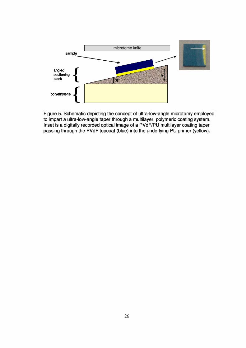
A schematic of the ULAM apparatus employed in the production of ultra-low-angle
tapers is presented in Figure 5. The ULAM processing of samples was carried out on
a Microm HM355S motorised rotary microtome (Optech Scientific Instruments,
Thame, UK) equipped with a standard specimen clamp and a tungsten carbide knife.
The ultra-low-angle sectioning blocks (~3.5 × 3.5 × 0.7 cm
3) were manufactured in-
house from high-quality steel. The ultra-low-angle sectioning blocks have one 3.5 ×
3.5 cm2 tapered face raised by a defined amount (in µm) relative to the parallel edge
of the tapered face. A detailed description of the ULAM procedure can be found
elsewhere. [9] The ultra-low-angle taper passing through the PVdF/PU coatings
employed here were produced using an ultra-low-angle sectioning block possessing a
200 µm rise, giving a theoretical taper angle of ~0.33°.
Surface Analysis by XPS.
XPS analyses were performed on a Thermo VG Scientific (East Grinstead, UK)
Sigma Probe spectrometer. The instrument employs a monochromated AlKα X-ray
9
source (hν = 1486.6 eV) which was used at 300 W (15 kV x 20 mA). The area of
analysis was approximately 500 µm diameter for the PVdF topcoat and PU primer
surfaces analysed. A 200 µm diameter area of analysis and a 230 µm interval size
were employed for the PVdF/PU ULAM taper sample linescan analyses. The pass
energy was set at 20 eV for core level high-resolution spectra of all elements of
interest and at 100 eV for all survey spectra. Charge compensation was achieved
using an electron flood gun. The coating samples were held in place on the
instruments sample stage by a sprung Cu/Be clip.
Surface Analysis by ToF-SIMS.
ToF-SIMS mass spectra analyses were performed on a VG Scientific (East Grinstead,
UK) Reflectron ToF-SIMS spectrometer. This instrument is equipped with a MIG
300PB pulsed liquid gallium ion source and a two-stage reflectron time-of-flight
analyser. Static SIMS conditions (ion dose < 1013
ions/cm2) were employed with a 16
keV beam, delivering 2 nA of current. The region of the surface analysed was a 500
µm wide square rastered area. Mass spectra in the mass range 0-400 m/z, in the
positive ion acquisition mode were acquired.
10
Results and Discussion :
The polyester/polyurethane based coating formulation constituted the model PU
primer system on aluminium substrate. The said primer is based on a commercial,
‘real world’ formulation and hence is a complex mixture designed to produce a
coating/paint that possesses a range of properties including adhesion, formability and
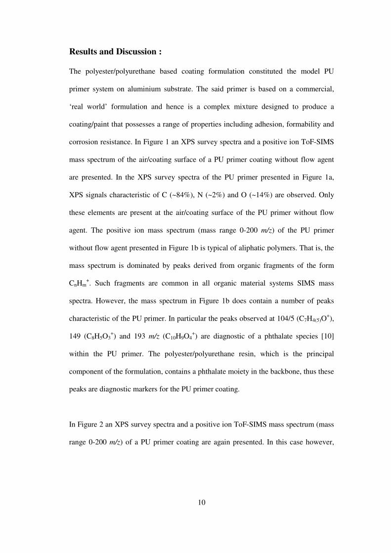
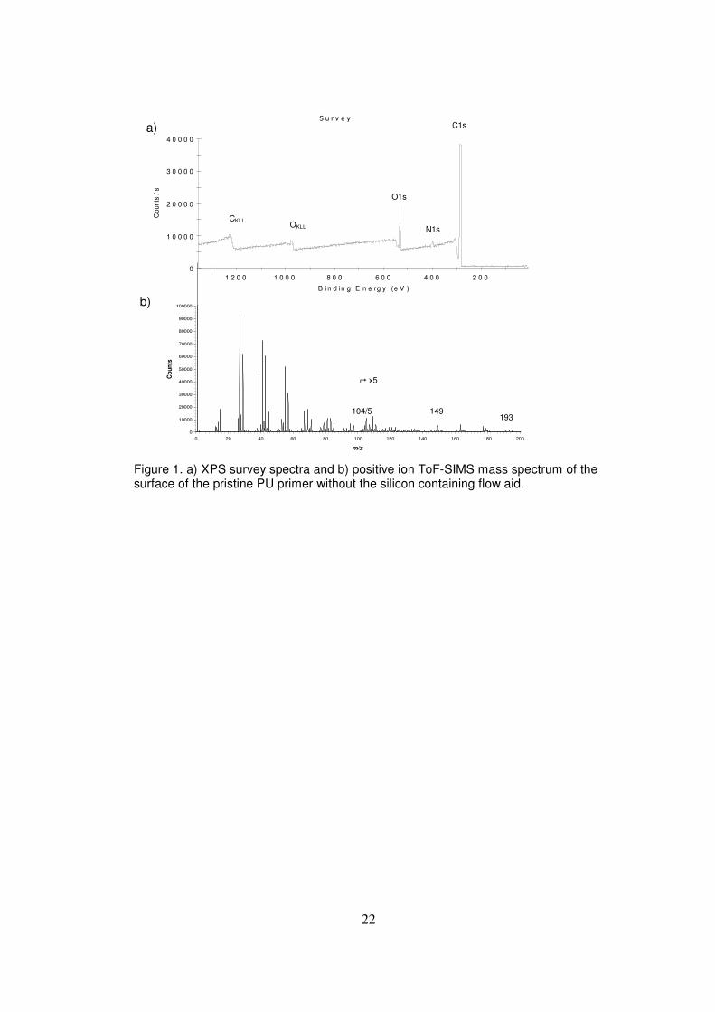
corrosion resistance. In Figure 1 an XPS survey spectra and a positive ion ToF-SIMS
mass spectrum of the air/coating surface of a PU primer coating without flow agent
are presented. In the XPS survey spectra of the PU primer presented in Figure 1a,
XPS signals characteristic of C (~84%), N (~2%) and O (~14%) are observed. Only
these elements are present at the air/coating surface of the PU primer without flow
agent. The positive ion mass spectrum (mass range 0-200 m/z) of the PU primer
without flow agent presented in Figure 1b is typical of aliphatic polymers. That is, the
mass spectrum is dominated by peaks derived from organic fragments of the form
CnHm+. Such fragments are common in all organic material systems SIMS mass
spectra. However, the mass spectrum in Figure 1b does contain a number of peaks
characteristic of the PU primer. In particular the peaks observed at 104/5 (C7H4(5)O+),
149 (C8H5O3+) and 193 m/z (C10H9O4
+) are diagnostic of a phthalate species [10]
within the PU primer. The polyester/polyurethane resin, which is the principal
component of the formulation, contains a phthalate moiety in the backbone, thus these
peaks are diagnostic markers for the PU primer coating.
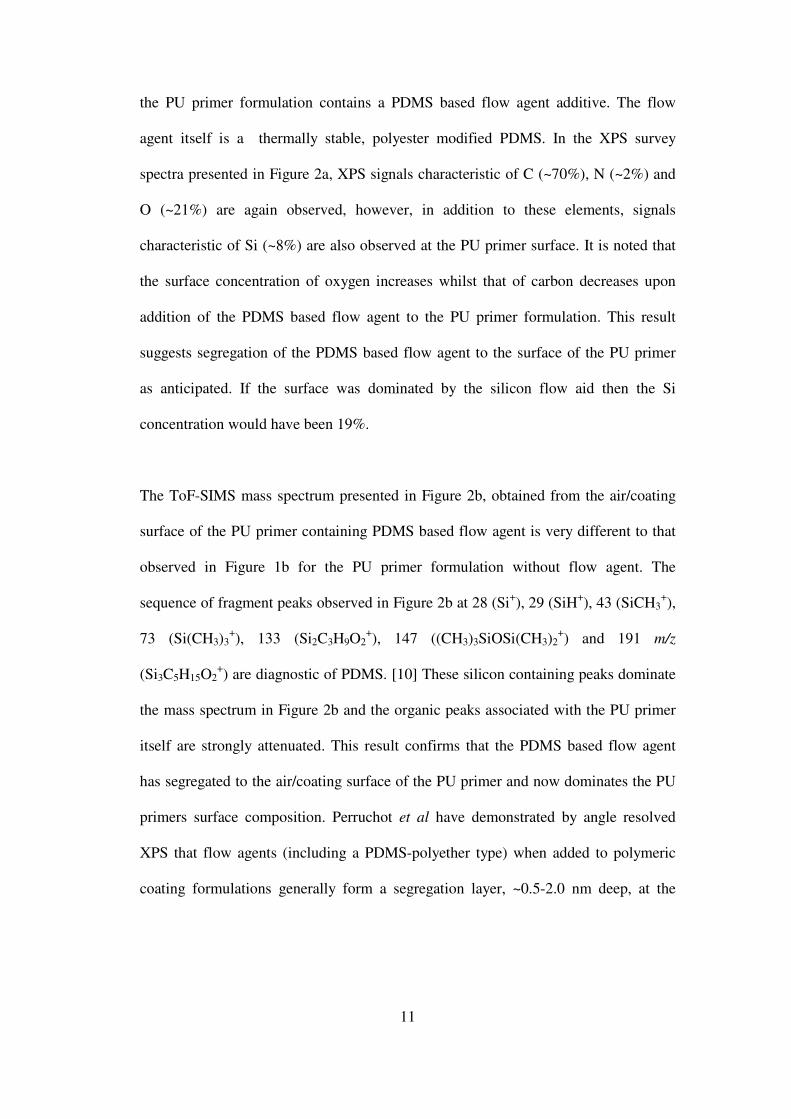
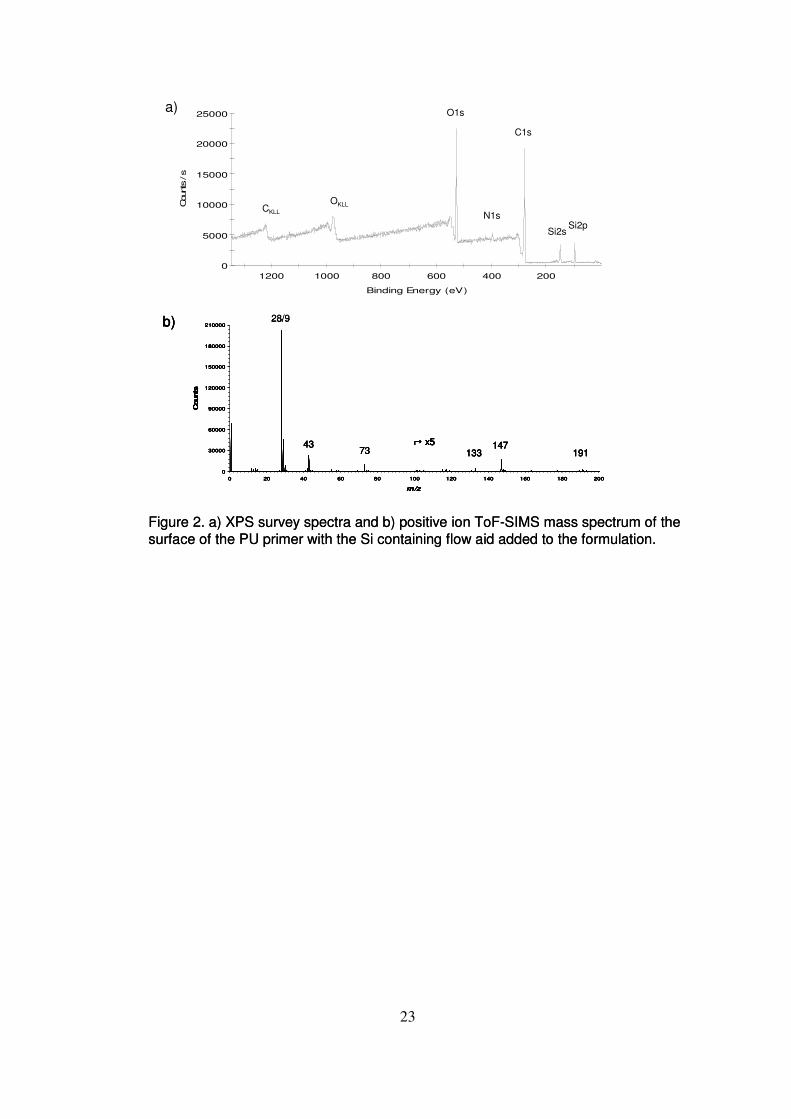
In Figure 2 an XPS survey spectra and a positive ion ToF-SIMS mass spectrum (mass
range 0-200 m/z) of a PU primer coating are again presented. In this case however,
11
the PU primer formulation contains a PDMS based flow agent additive. The flow
agent itself is a thermally stable, polyester modified PDMS. In the XPS survey
spectra presented in Figure 2a, XPS signals characteristic of C (~70%), N (~2%) and
O (~21%) are again observed, however, in addition to these elements, signals
characteristic of Si (~8%) are also observed at the PU primer surface. It is noted that
the surface concentration of oxygen increases whilst that of carbon decreases upon
addition of the PDMS based flow agent to the PU primer formulation. This result
suggests segregation of the PDMS based flow agent to the surface of the PU primer
as anticipated. If the surface was dominated by the silicon flow aid then the Si
concentration would have been 19%.
The ToF-SIMS mass spectrum presented in Figure 2b, obtained from the air/coating
surface of the PU primer containing PDMS based flow agent is very different to that
observed in Figure 1b for the PU primer formulation without flow agent. The
sequence of fragment peaks observed in Figure 2b at 28 (Si+), 29 (SiH
+), 43 (SiCH3
+),
73 (Si(CH3)3+), 133 (Si2C3H9O2
+), 147 ((CH3)3SiOSi(CH3)2
+) and 191 m/z
(Si3C5H15O2+) are diagnostic of PDMS. [10] These silicon containing peaks dominate
the mass spectrum in Figure 2b and the organic peaks associated with the PU primer
itself are strongly attenuated. This result confirms that the PDMS based flow agent
has segregated to the air/coating surface of the PU primer and now dominates the PU
primers surface composition. Perruchot et al have demonstrated by angle resolved
XPS that flow agents (including a PDMS-polyether type) when added to polymeric
coating formulations generally form a segregation layer, ~0.5-2.0 nm deep, at the
12
surface of the coating. [3] It is reasonable to assume that the PDMS based flow agent
employed here has acted in a similar manner and formed a segregation layer at the
air/coating surface of the PU primer. N.B. nitrogen is seen in XPS but not SIMS and
more of it than in polyacrylate flow aid systems. Hence the flow aid layer is very thin.
This is substantiated by the low concentration of silicon detected (8% vs 19%).
Having characterised the PU primer surfaces, a PVdF based topcoat was applied to
each of the PU primer formulations and the resulting PVdF topcoat air/coating
surfaces investigated by XPS and ToF-SIMS. Due to its similarity to a commercial
system the model PVdF topcoat formulation employed is a complex mixture
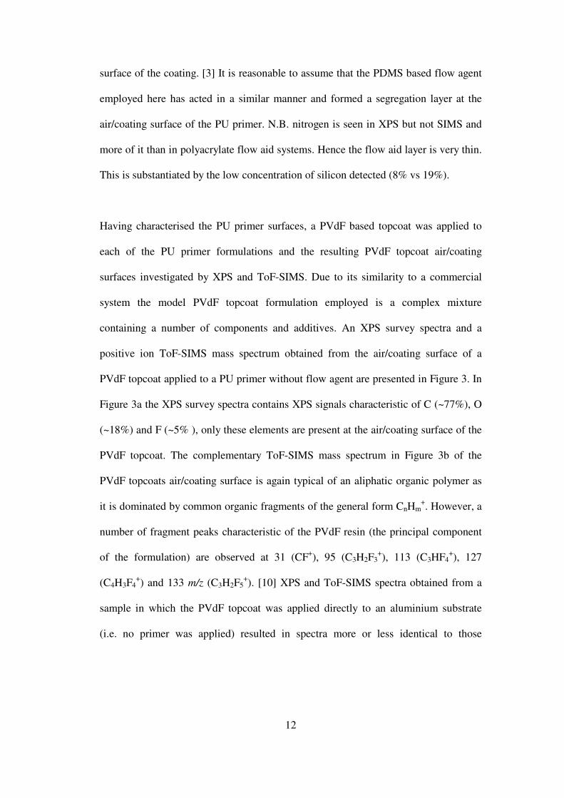
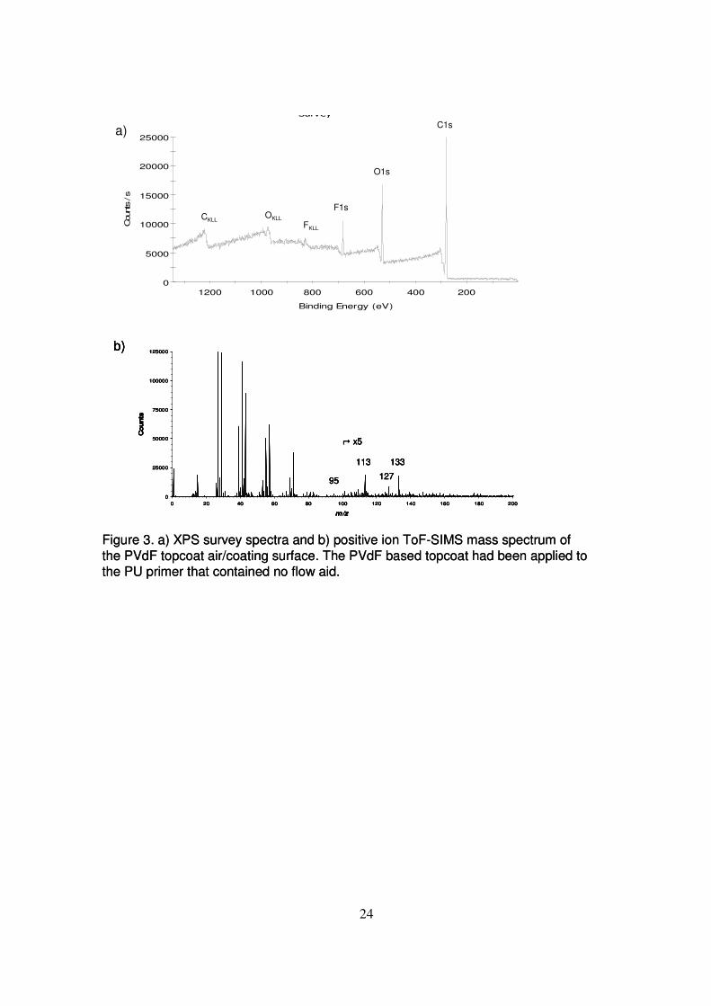
containing a number of components and additives. An XPS survey spectra and a
positive ion ToF-SIMS mass spectrum obtained from the air/coating surface of a
PVdF topcoat applied to a PU primer without flow agent are presented in Figure 3. In
Figure 3a the XPS survey spectra contains XPS signals characteristic of C (~77%), O
(~18%) and F (~5% ), only these elements are present at the air/coating surface of the
PVdF topcoat. The complementary ToF-SIMS mass spectrum in Figure 3b of the
PVdF topcoats air/coating surface is again typical of an aliphatic organic polymer as
it is dominated by common organic fragments of the general form CnHm+. However, a
number of fragment peaks characteristic of the PVdF resin (the principal component
of the formulation) are observed at 31 (CF+), 95 (C3H2F3
+), 113 (C3HF4
+), 127
(C4H3F4+) and 133 m/z (C3H2F5
+). [10] XPS and ToF-SIMS spectra obtained from a
sample in which the PVdF topcoat was applied directly to an aluminium substrate
(i.e. no primer was applied) resulted in spectra more or less identical to those
13
observed in Figure 3. These results indicate the PVdF topcoats air/coating surface is
highly organic in nature and that some of the PVdF resin is incorporated into the
air/coating surface. Previous results have indicated higher values of fluorine at the
air/coating interface indicating, that in this case, the surface is dominated by
something other than PVdF, probably the acrylic resin.
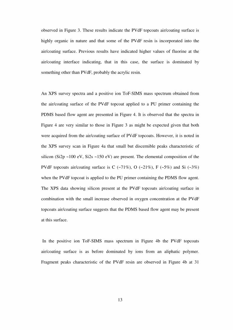
An XPS survey spectra and a positive ion ToF-SIMS mass spectrum obtained from
the air/coating surface of the PVdF topcoat applied to a PU primer containing the
PDMS based flow agent are presented in Figure 4. It is observed that the spectra in
Figure 4 are very similar to those in Figure 3 as might be expected given that both
were acquired from the air/coating surface of PVdF topcoats. However, it is noted in
the XPS survey scan in Figure 4a that small but discernible peaks characteristic of
silicon (Si2p ~100 eV, Si2s ~150 eV) are present. The elemental composition of the
PVdF topcoats air/coating surface is C (~71%), O (~21%), F (~5%) and Si (~3%)
when the PVdF topcoat is applied to the PU primer containing the PDMS flow agent.
The XPS data showing silicon present at the PVdF topcoats air/coating surface in
combination with the small increase observed in oxygen concentration at the PVdF
topcoats air/coating surface suggests that the PDMS based flow agent may be present
at this surface.
In the positive ion ToF-SIMS mass spectrum in Figure 4b the PVdF topcoats
air/coating surface is as before dominated by ions from an aliphatic polymer.
Fragment peaks characteristic of the PVdF resin are observed in Figure 4b at 31
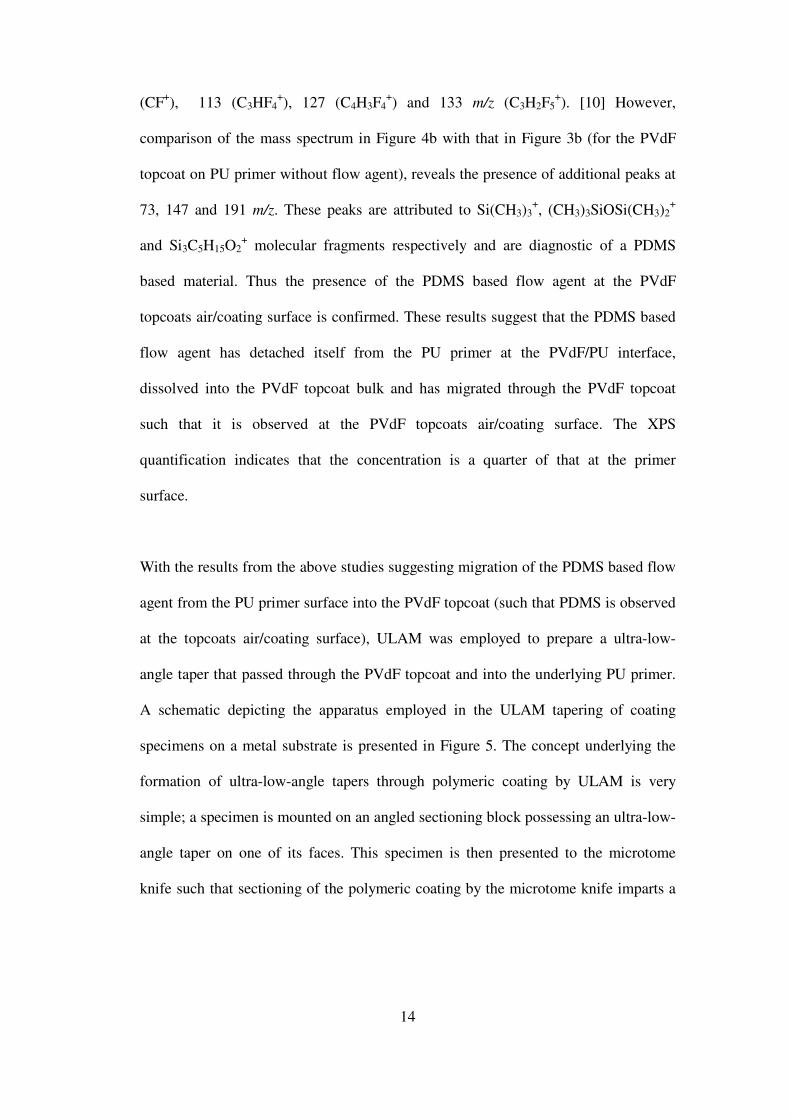
14
(CF+), 113 (C3HF4
+), 127 (C4H3F4
+) and 133 m/z (C3H2F5
+). [10] However,
comparison of the mass spectrum in Figure 4b with that in Figure 3b (for the PVdF
topcoat on PU primer without flow agent), reveals the presence of additional peaks at
73, 147 and 191 m/z. These peaks are attributed to Si(CH3)3+, (CH3)3SiOSi(CH3)2
+
and Si3C5H15O2+ molecular fragments respectively and are diagnostic of a PDMS
based material. Thus the presence of the PDMS based flow agent at the PVdF
topcoats air/coating surface is confirmed. These results suggest that the PDMS based
flow agent has detached itself from the PU primer at the PVdF/PU interface,
dissolved into the PVdF topcoat bulk and has migrated through the PVdF topcoat
such that it is observed at the PVdF topcoats air/coating surface. The XPS
quantification indicates that the concentration is a quarter of that at the primer
surface.
With the results from the above studies suggesting migration of the PDMS based flow
agent from the PU primer surface into the PVdF topcoat (such that PDMS is observed
at the topcoats air/coating surface), ULAM was employed to prepare a ultra-low-
angle taper that passed through the PVdF topcoat and into the underlying PU primer.
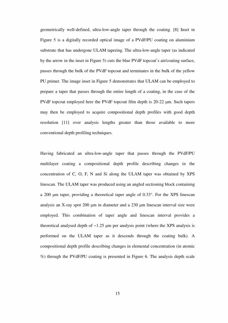
A schematic depicting the apparatus employed in the ULAM tapering of coating
specimens on a metal substrate is presented in Figure 5. The concept underlying the
formation of ultra-low-angle tapers through polymeric coating by ULAM is very
simple; a specimen is mounted on an angled sectioning block possessing an ultra-low-
angle taper on one of its faces. This specimen is then presented to the microtome
knife such that sectioning of the polymeric coating by the microtome knife imparts a
15
geometrically well-defined, ultra-low-angle taper through the coating. [8] Inset in
Figure 5 is a digitally recorded optical image of a PVdF/PU coating on aluminium
substrate that has undergone ULAM tapering. The ultra-low-angle taper (as indicated
by the arrow in the inset in Figure 5) cuts the blue PVdF topcoat’s air/coating surface,
passes through the bulk of the PVdF topcoat and terminates in the bulk of the yellow
PU primer. The image inset in Figure 5 demonstrates that ULAM can be employed to
prepare a taper that passes through the entire length of a coating, in the case of the
PVdF topcoat employed here the PVdF topcoat film depth is 20-22 µm. Such tapers
may then be employed to acquire compositional depth profiles with good depth
resolution [11] over analysis lengths greater than those available to more
conventional depth profiling techniques.
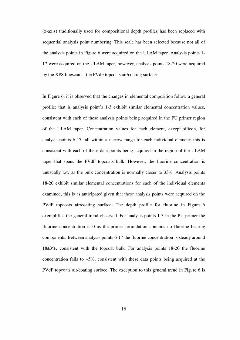
Having fabricated an ultra-low-angle taper that passes through the PVdF/PU
multilayer coating a compositional depth profile describing changes in the
concentration of C, O, F, N and Si along the ULAM taper was obtained by XPS
linescan. The ULAM taper was produced using an angled sectioning block containing
a 200 µm taper, providing a theoretical taper angle of 0.33°. For the XPS linescan
analysis an X-ray spot 200 µm in diameter and a 230 µm linescan interval size were
employed. This combination of taper angle and linescan interval provides a
theoretical analysed depth of ~1.25 µm per analysis point (where the XPS analysis is
performed on the ULAM taper as it descends through the coating bulk). A
compositional depth profile describing changes in elemental concentration (in atomic
%) through the PVdF/PU coating is presented in Figure 6. The analysis depth scale
16
(x-axis) traditionally used for compositional depth profiles has been replaced with
sequential analysis point numbering. This scale has been selected because not all of
the analysis points in Figure 6 were acquired on the ULAM taper. Analysis points 1-
17 were acquired on the ULAM taper, however, analysis points 18-20 were acquired
by the XPS linescan at the PVdF topcoats air/coating surface.
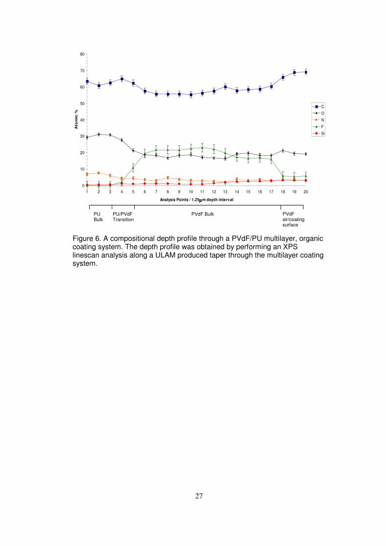
In Figure 6, it is observed that the changes in elemental composition follow a general
profile; that is analysis point’s 1-3 exhibit similar elemental concentration values,
consistent with each of these analysis points being acquired in the PU primer region
of the ULAM taper. Concentration values for each element, except silicon, for
analysis points 6-17 fall within a narrow range for each individual element; this is
consistent with each of these data points being acquired in the region of the ULAM
taper that spans the PVdF topcoats bulk. However, the fluorine concentration is
unusually low as the bulk concentration is normally closer to 33%. Analysis points
18-20 exhibit similar elemental concentrations for each of the individual elements
examined, this is as anticipated given that these analysis points were acquired on the
PVdF topcoats air/coating surface. The depth profile for fluorine in Figure 6
exemplifies the general trend observed. For analysis points 1-3 in the PU primer the
fluorine concentration is 0 as the primer formulation contains no fluorine bearing
components. Between analysis points 6-17 the fluorine concentration is steady around
18±3%, consistent with the topcoat bulk. For analysis points 18-20 the fluorine
concentration falls to ~5%, consistent with these data points being acquired at the
PVdF topcoats air/coating surface. The exception to this general trend in Figure 6 is
17
the depth profile for silicon. It is observed in Figure 6 that the silicon concentration
increases as the linescan analysis progresses through the PVdF topcoat and that the
silicon concentration maximum is observed at the analysis points obtained at the
PVdF topcoats air/coating surface.
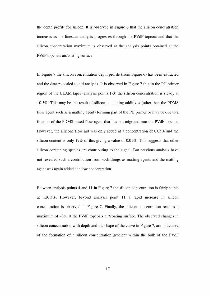
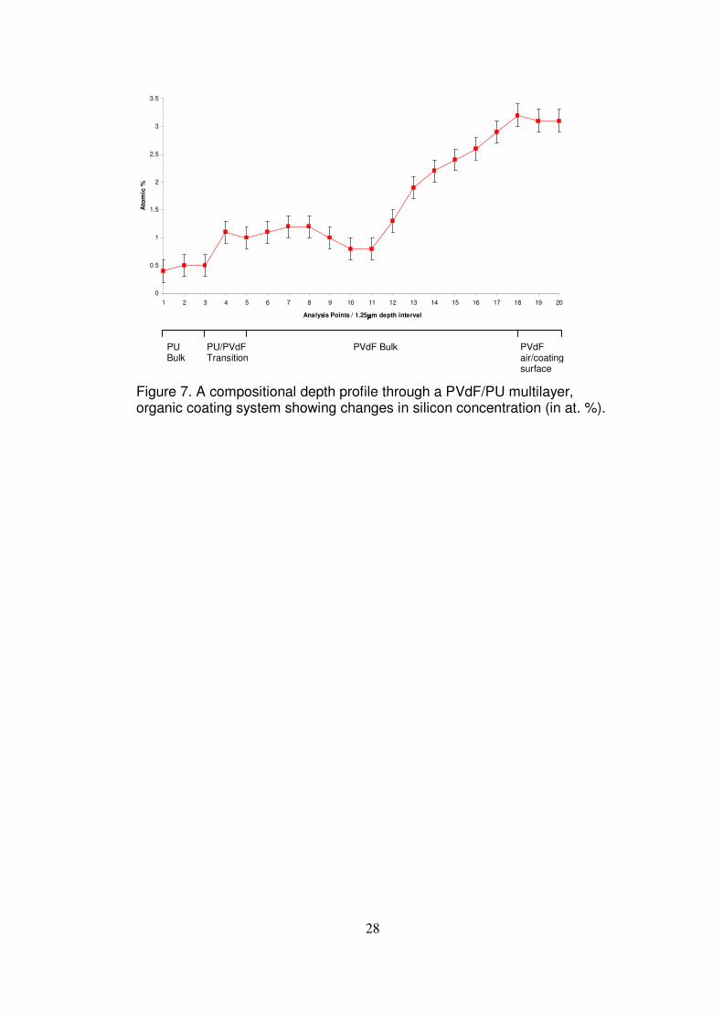
In Figure 7 the silicon concentration depth profile (from Figure 6) has been extracted
and the data re-scaled to aid analysis. It is observed in Figure 7 that in the PU primer
region of the ULAM taper (analysis points 1-3) the silicon concentration is steady at
~0.5%. This may be the result of silicon containing additives (other than the PDMS
flow agent such as a matting agent) forming part of the PU primer or may be due to a
fraction of the PDMS based flow agent that has not migrated into the PVdF topcoat.
However, the silicone flow aid was only added at a concentration of 0.05% and the
silicon content is only 19% of this giving a value of 0.01%. This suggests that other
silicon containing species are contributing to the signal. But previous analysis have
not revealed such a contribution from such things as matting agents and the matting
agent was again added at a low concentration.
Between analysis points 4 and 11 in Figure 7 the silicon concentration is fairly stable
at 1±0.3%. However, beyond analysis point 11 a rapid increase in silicon
concentration is observed in Figure 7. Finally, the silicon concentration reaches a
maximum of ~3% at the PVdF topcoats air/coating surface. The observed changes in
silicon concentration with depth and the shape of the curve in Figure 7, are indicative
of the formation of a silicon concentration gradient within the bulk of the PVdF
18
topcoat. The shape of the silicon concentration profile in Figure 7 is clear evidence
that the process at work is not diffusion driven, as these results show a clear example
of “uphill” diffusion. These results suggest that the PDMS based flow agent used in
the PU primer formulation is highly mobile. The PDMS based flow agent segregation
layer known to form at the PU primer air/coating surface has detached from the PU
primer and migrated into the PVdF topcoat. Furthermore, not only has the PDMS
based flow agent migrated into the PVdF topcoat but it is segregating to the PVdF
topcoats air/coating surface where it presumably has an effect upon the properties
exhibited by this surface. Such segregation of a PDMS based flow agent to the
air/coating surface can be understood in terms of the need of the lowest surface free
energy component of the coating (in this case the PDMS) to segregate to the
air/coating surface (Gibbsian segregation). Thus the PDMS based flow agent that has
migrated into the PVdF topcoat and segregated to the air/coating surface of the PVdF
topcoat in order to minimise the surface free energy of the coating and by doing so
has created the silicon concentration gradient observed in Figure 7. A similar result
has been reported by Hinder et al, where studies on adhesion failure in multilayer
organic coatings indicated migration and segregation of a flow agent, included in the
PU primer, into a PVdF topcoat. [12] The difficulties with this conventional
explanation are that the silicone was added at a very low concentration to the primer
and that the step increase would be expected to occur just at the PVdF/air interface
not 10 microns below it.
19
High silicon concentrations at the PVdF/air interface could be explained by the flow
aid dissolving and segregating to this interface driven by the reduction in surface
tension that would then occur. However, the only way to explain the distribution
observed is to invoke a migration mechanism that occurs during and after the
microtoming action. That is a substantial portion of the flow aid on the surface of the
primer dissolves into the PVdF topcoat and segregates to the PVdF/air interface.
Once the coating is cut on the microtome the silicone migrates from the top of the
coating to a distance of about 30 µm along the freshly cut face at the same time the
silicone remaining at the interface migrates in both directions. The result suggests
several dynamic processes are occurring which could only be discerned with time
resolved application procedures. Firstly, the flow aid must dissolve into the PVdF at a
certain rate and then it vacates the interfacial region and segregates to the air/coating
surface. The dissolution process is slowed by the concentration of the flow aid in the
interfacial region of the liquid PVdF and by the reduced solvent concentration caused
by the evaporation of this component during the heating of the panel to its peak metal
temperature. Some of the silicone may have become chemically bound on the primer
surface but again this needs further investigation.
Conclusions :
The XPS and TOF-SIMS characterisation of a model PU primer based on a ‘real
world’ commercial formulation, with and without the addition of a PDMS based flow
agent, has been demonstrated. It was observed that the inclusion of the PDMS based
20
flow agent in the PU primer formulation results in the segregation of the flow agent to
the PU primer air/coating surface where it dominates the PU primer surface
composition. XPS and ToF-SIMS characterisation of the air/coating surface of a
model PVdF topcoat (itself based on a ‘real world’ commercial formulation) applied
to the PU primer (with and without flow agent) revealed the presence of PDMS
material at the PVdF topcoats air/coating surface even though no PDMS based
components or additives are included in the PVdF topcoat formulation. These results
suggest migration of the PDMS based flow agent from the PU/PVdF interface into
and through the PVdF topcoat.
The fabrication of a ULAM taper passing through the entire depth of the PVdF
topcoat (~20 µm) and into the underlying PU primer enabling compositional depth
profiling over an analysis depth of ~25 µm was demonstrated. Analysis of the silicon
concentration profile indicates that the PDMS based flow agent does not diffuse into
the PVdF topcoat after gelation but migrates into the PVdF topcoat during the ‘curing
process’ and segregates to the PVdF topcoats air/coating surface. In addition, the
shape of the silicon concentration profile indicates that the segregation of the PDMS
based flow agent to the PVdF topcoats air/coating surface results in the formation of a
silicon concentration gradient (~10 µm deep) running from the PVdF topcoat bulk to
the air/coating surface. Such migration and segregation phenomena based on material
mobility and the minimisation of surface free energies may have profound
implications for the scientists and engineers involved in formulating coatings and
paints.
21
Acknowledgements :
The authors acknowledge the financial support of the EPSRC (grant no. GR/N65745).
References :
[1] Leadley SR, Watts JF, Blomfield CJ, Lowe C, Surface and Interface Analysis 26
(1998) 444.
[2] Watts JF, Abel M-L, Perruchot C, Lowe C, Maxted JT, White RG, J. Electron
Spectrosc. Relat. Phenom. 121 (2001) 233.
[3] Perruchot C, Abel M-L, Watts JF, Lowe C, Maxted JT, White RG, Surface and
Interface Analysis 34 (2002) 570.
[4] Hinder SJ, Lowe C, Maxted JT, Watts JF, Surface and Interface Analysis 36
(2004) 1575.
[5] Horgnies M, Darque-Ceretti E, Combarieu R, Progress in Organic Coatings 47
(2003) 154.
[6] Haack LP, Straccia AM, Holubka JW, Bhurke A, Xie M, Drzal LT, Surface and
Interface Analysis 29 (2000) 829.
[7] Hajas J. In Additives for Coatings. Bieleman J (ed.). Wiley-VCH Verlang:
Weinheim, Germany, 2000; Chapter 6.1 Levelling Additives, 163-179 .
[8] Hinder SJ, Watts JF, Lowe C, Surface and Interface Analysis 36 (2004) 1032.
[9] Hinder SJ, Watts JF, Maxted JT, In press Journal of Materials Science 2005.
[10] In The Wiley Static SIMS Library (Version 2), vol. 2. Vickerman JC, Briggs D,
Henderson A (eds). John Wiley: Chichester, 1999; Organic Materials - Homo
Polymers.
[11] Guichenuy M, Watts JF, Abel M-L, Brown AM, Audenaert M, Amouroux N,
Surface and Interface Analysis 36 (2004) 685.
[12] Hinder SJ, Lowe C, Maxted JT, Watts JF, Accepted for publication in Progress
in Organic Coatings, November 2004.
22
Figure 1. a) XPS survey spectra and b) positive ion ToF-SIMS mass spectrum of the surface of the pristine PU primer without the silicon containing flow aid.
0
1 0 0 0 0
2 0 0 0 0
3 0 0 0 0
4 0 0 0 0
2 0 04 0 06 0 08 0 01 0 0 01 2 0 0
Counts
/ s
B in d in g E n e rg y (e V )
S u r v e y
a)
O1s
N1s
C1s
CKLL OKLL
0
10000
20000
30000
40000
50000
60000
70000
80000
90000
100000
0 20 40 60 80 100 120 140 160 180 200
m/z
Co
un
ts
b)
� x5
149 193
104/5
23
Figure 2. a) XPS survey spectra and b) positive ion ToF-SIMS mass spectrum of the surface of the PU primer with the Si containing flow aid added to the formulation.
0
5000
10000
15000
20000
25000
20040060080010001200
Counts
/ s
Binding Energy (eV)
a)
C1s
OKLL
Si2sSi2p
N1s
O1s
CKLL
0
30000
60000
90000
120000
150000
180000
210000
0 20 40 60 80 100 120 140 160 180 200
m/z
Counts
� x5
b)
191
28/9
4373 133
147
0
5000
10000
15000
20000
25000
20040060080010001200
Counts
/ s
Binding Energy (eV)
a)
C1s
OKLL
Si2sSi2p
N1s
O1s
CKLL
0
5000
10000
15000
20000
25000
20040060080010001200
Counts
/ s
Binding Energy (eV)
a)
0
5000
10000
15000
20000
25000
20040060080010001200
Counts
/ s
Binding Energy (eV)
a)
C1s
OKLL
Si2sSi2p
N1s
O1s
CKLL
0
30000
60000
90000
120000
150000
180000
210000
0 20 40 60 80 100 120 140 160 180 200
m/z
Counts
� x5
b)
191
28/9
4373 133
147
0
30000
60000
90000
120000
150000
180000
210000
0 20 40 60 80 100 120 140 160 180 200
m/z
Counts
� x5
b)
0
30000
60000
90000
120000
150000
180000
210000
0 20 40 60 80 100 120 140 160 180 200
m/z
Counts
� x5
b)
191
28/9
4373 133
147
24
Figure 3. a) XPS survey spectra and b) positive ion ToF-SIMS mass spectrum of
the PVdF topcoat air/coating surface. The PVdF based topcoat had been applied to the PU primer that contained no flow aid.
0
5000
10000
15000
20000
25000
20040060080010001200
Counts
/ s
Binding Energy (eV)
Survey
a)
F1s
O1s
C1s
CKLLOKLL
FKLL
0
25000
50000
75000
100000
125000
0 20 40 60 80 100 120 140 160 180 200
m/z
Counts
� x5
b)
113 133
12795
0
5000
10000
15000
20000
25000
20040060080010001200
Counts
/ s
Binding Energy (eV)
Survey
a)
0
5000
10000
15000
20000
25000
20040060080010001200
Counts
/ s
Binding Energy (eV)
Survey
a)
F1s
O1s
C1s
CKLLOKLL
FKLL
0
25000
50000
75000
100000
125000
0 20 40 60 80 100 120 140 160 180 200
m/z
Counts
� x5
b)
113 133
12795
0
25000
50000
75000
100000
125000
0 20 40 60 80 100 120 140 160 180 200
m/z
Counts
� x5
b)
113 133
12795

25
Figure 4. a) XPS survey spectra and b) positive ion ToF-SIMS mass spectrum of the PVdF topcoat air/coating surface. The PVdF topcoat was applied to the PU primer containing the Si based flow aid.
0
50 00
100 00
150 00
200 00
250 00
300 00
350 00
020040060080010001200
B in d ing E n e rg y (e V )
Co
unts
/s
a)
Si2s Si2p
F1s
O1s
C1s
CKLLOKLL
FKLL
0
10000
20000
30000
40000
50000
60000
70000
80000
0 20 40 60 80 100 120 140 160 1 80 20 0
m /z
Co
un
ts
x5
b)
73113 133
147
191
Figure 4. a) XPS survey spectra and b) positive ion ToF-SIMS mass spectrum of the PVdF topcoat air/coating surface. The PVdF topcoat was applied to the PU primer containing the Si based flow aid.
0
50 00
100 00
150 00
200 00
250 00
300 00
350 00
020040060080010001200
B in d ing E n e rg y (e V )
Co
unts
/s
a)
Si2s Si2p
F1s
O1s
C1s
CKLLOKLL
FKLL
0
50 00
100 00
150 00
200 00
250 00
300 00
350 00
020040060080010001200
B in d ing E n e rg y (e V )
Co
unts
/s
0
50 00
100 00
150 00
200 00
250 00
300 00
350 00
020040060080010001200
B in d ing E n e rg y (e V )
Co
unts
/s
a)
Si2s Si2p
F1s
O1s
C1s
CKLLOKLL
FKLL
0
10000
20000
30000
40000
50000
60000
70000
80000
0 20 40 60 80 100 120 140 160 1 80 20 0
m /z
Co
un
ts
x5
b)
73113 133
147
191
0
10000
20000
30000
40000
50000
60000
70000
80000
0 20 40 60 80 100 120 140 160 1 80 20 0
m /z
Co
un
ts
x5
b)
0
10000
20000
30000
40000
50000
60000
70000
80000
0 20 40 60 80 100 120 140 160 1 80 20 0
m /z
Co
un
ts
x5
b)
73113 133
147
191
26
Figure 5. Schematic depicting the concept of ultra-low-angle microtomy employed
to impart a ultra-low-angle taper through a multilayer, polymeric coating system.
Inset is a digitally recorded optical image of a PVdF/PU multilayer coating taper passing through the PVdF topcoat (blue) into the underlying PU primer (yellow).
sample
θθθ
h
}
polyethylene
angled
sectioning block
}
microtome knife
sample
θθθ
h
θθθθθθ
hh
}
polyethylene
angled
sectioning block
}}
polyethylene
}
polyethylene
angled
sectioning block
}angled
sectioning block
}
microtome knifemicrotome knife
27
Figure 6. A compositional depth profile through a PVdF/PU multilayer, organic coating system. The depth profile was obtained by performing an XPS linescan analysis along a ULAM produced taper through the multilayer coating system.
PVdF Bulk PU Bulk
PU/PVdF Transition
PVdF air/coating surface
0
10
20
30
40
50
60
70
80
1 2 3 4 5 6 7 8 9 10 11 12 13 14 15 16 17 18 19 20
Analysis Points / 1.25µµµµ m depth interval
Ato
mic
%
C
O
N
F
Si
28
Figure 7. A compositional depth profile through a PVdF/PU multilayer, organic coating system showing changes in silicon concentration (in at. %).
0
0.5
1
1.5
2
2.5
3
3.5
1 2 3 4 5 6 7 8 9 10 11 12 13 14 15 16 17 18 19 20
Analysis Points / 1.25µµµµm depth interval
Ato
mic
%
PVdF Bulk PU Bulk
PU/PVdF Transition
PVdF air/coating surface