Embed Size (px)
Citation preview
Migratable User Interface Descriptions inComponent-Based Development
Kris Luyten, Chris Vandervelpen, Karin Coninxc©2002 Springer-Verlag
http://www.springer.de/comp/lncs/index.html
Expertise Centre for Digital MediaLimburgs Universitair Centrum
Wetenschapspark 2B-3590 Diepenbeek-Belgium
{kris.luyten, chris.vandervelpen, karin.coninx}@luc.ac.be
Abstract. In this paper we describe how a component-based approachcan be combined with a user interface (UI) description language to getmore flexible and adaptable UIs for embedded systems and mobile com-puting devices. We envision a new approach for building adaptable userinterfaces for embedded systems, which can migrate from one device toanother. Adaptability to the device constraints is especially importantfor adding reusability and extensibility to UIs for embedded systems:this way they are ready to keep pace with new technologies.
1 Introduction
The market of embedded systems and mobile computing devices is a fast evolvingmarket. New technologies are introduced at a very high rate. One of the con-sequences of this evolution is the constant reinvention of user interfaces (UIs)for these devices. They lack the adaptability and flexibility to be deployed fornew devices (possibly using new interaction techniques) without reprogrammingthem. One of the results of the SEESCOA1 [13] project is a common softwareplatform, using components for embedded systems on a Java Virtual Machine.Using this specific component-based approach for embedded systems, we candevelop a framework for UIs adapting to the environment and device specificconstraints as well as encourage reuse. The SEESCOA method is a component-based development approach combined with ideas of contract-based specificationfor software objects.
This paper presents our ongoing research on the possibility of creating aframework that will allow for runtime migratable UIs, which are independent ofthe target software platform, the target device and the interaction modalities.These UIs are merely considered as a presentation of a single service or of more1 Software Engineering for Embedded Systems using a Component-Oriented
Approach, http://www.cs.kuleuven.ac.be/cwis/research/distrinet/projects/SEESCOA/
2. DESCRIBING USER INTERFACES FOR EMBEDDED SYSTEMS
functionally grouped services. We try to extend the work presented in [3, 14, 10]which all focus on how to abstract a UI for a platform- and device-independentusage. Like work presented in [9, 6, 2], we also use markup languages to describeUIs. However, our work goes a step further by allowing runtime generation ofUIs using a markup language. These ideas are combined with a component-based approach allowing the designer to design UIs for particular components,which can be merged automatically at a later stage. This enables UI designersto concentrate on what is important for multi-device UIs: how to present the UIin a structured and logical manner. Unlike approaches like described in [10], wetry to develop a truly distributed component-based approach, without relyingon a client-server architecture.
Throughout the text we will use an example case study: a small camerasurveillance system using 4 cameras. Each camera will be represented by a com-ponent. It will be possible to combine the four cameras by using a Mosaic com-ponent. This should make it possible to observe four cameras at the same time.Each camera has its own properties: some cameras can zoom in and out, otheralso allow to change the framerate,. . .
The next section, section 2, takes a look at how UIs for embedded systemsor mobile computing devices can be described with a UI description language.An overview of related work is provided. Continuing with section 3, we showhow these descriptions can be combined with software components in general,and SEESCOA components in particular. The case-study is presented in moredetail to show the results of the approach proposed in this paper. In section4, we consider how using markup languages and a component-based approachcontributes to flexibility, adaptability and migratability of UIs. In particularattention is given to automatic layout management and multi-modal renderingpossibilities. Finally conclusions with regard to the current work and possibleextensions are formulated in section 6.
2 Describing User Interfaces For Embedded Systems
2.1 Abstracting the User Interface
When designing UIs for embedded systems, we should not take a widget-basedapproach, but an interaction- or task-based approach. We should be interestedin how a user can interact with the offered service and how this can be instan-tiated afterwards using a concrete widget set. This kind of approach is thor-oughly examined in [11] and is important in particular for embedded devices.Too much time is spent reinventing UIs for accessing the same services as tech-nology evolves. One of the major enhancements we envision is the separation ofUI design and low-level programming. Until now, embedded systems program-mers have a dual task: implementing the actual embedded system and designingand implementing the UI for this system. The main reason for this way of work-ing is the required technical knowledge and background of the system to providea UI for it. Therefore we use a markup language to describe the UI for embeddedsystems and mobile computing devices.
c©2002 Springer-Verlag 2
2. DESCRIBING USER INTERFACES FOR EMBEDDED SYSTEMS
2.2 An XML-Based User Interface description
To describe a UI on a sufficiently abstract level the eXtensible Markup Language(XML)[5] is used. Listing 1.1 provides an example of how a UI can be describedin XML. There are already several propositions and real world examples of theusage of XML to describe UIs: [10, 1]. A list of advantages is given in [8]. One ofthe major advantages is that XML does not force any level of abstraction, so thislevel can be adapted to the requirements of the situation. Note that an XMLdocument can be presented as a tree which turns out to be a great advantage inour approach. There are other approaches for describing User Interfaces, but webelieve that an XML-based description offers the best solution in our component-based approach because of it heavily relies on hierarchical structures.
Listing 1.1. An example XML listing for a camera
<ui>
<title>Login</title>
<group name="videopanel">
<interactor>
<video name="video">
<text>Camera 2 video stream</text>
<mediasource>http://twiki.luc.ac.be/camera:8888</mediasource>
</video>
</interactor>
<interactor>
<range name="zoomrange">
<text>Zoom</text>
<min>-100</min>
<max>100</max>
<start>0</start>
<tick>25</tick>
<action>
<func service="Mosaic.camera2">setZoom</func>
<param name="zoomrange"/>
</action>
</range>
</interactor>
<interactor>
<range name="focusrange">
<text>Focus</text>
...
<action>
<func service="Mosaic.camera2">setFocus</func>
<param name="focusrange"/>
</action>
</range>
</interactor>
<interactor>
<button name="snapshot">
<text>Take snapshot</text>
c©2002 Springer-Verlag 3
2. DESCRIBING USER INTERFACES FOR EMBEDDED SYSTEMS
<action><func service="Mosaic.camera2">saveImage</func></action>
</button>
</interactor>
</group>
</ui>
The example listing (listing 1.1) is not simplified: the UI description is meantto be human-readable and machine-processable at the same time. The descrip-tion allows human users to specify the UI on a high level.
On the other hand, the structured and hierarchical approach by using XMLas a notational language to describe the UI allows machines to process and usethese descriptions without human intervention. Our notation uses a range of tagsthat are easy to read and understand for humans. In the current stage, a stableDocument Type Definition or XML Schema is not available because we do notconsider our specification to be complete. Nevertheless care has been taken to in-troduce no ambiguities in the specification and to enable easy migration to otherspecification languages, in case a certain XML-based notation for describing UIswill evolve into a standard.
The following interactors are currently supported by the system: range inter-actors, single and multiple choice interactors, a text interactor, push interactors(e.g. a button) and a canvas output interactor (e.g. a video stream). These canbe composed to represent a new interactor with combined functionality. Theavailable tags are still limited, but a lot of dialog-based UIs can already be im-plemented using these widgets (e.g. all kinds of web forms). There are two tagtypes which are of particular importance: group tags and action tags. Thegroup tags allow to group objects which have no meaning when they are sep-arated. An example of this is a “date interactor”: the interactors involved forfilling in a date should not be separated (listing 1.2). Groups can be nested: theycan be hierarchically structured. This enables us to reuse groups of interactors,and make new composed groups. The action tags allow a user to specify whichaction to fire if the interactor (which is the parent node) is manipulated. Theaction tag specifies the target (this can be a class name, a server,. . . ) and thefunctionality that has to be invoked from this target. It is also possible to specifyparameters and use the names of the interactors or groups for these parameters.Our system will automatically extract the current content out of the interactoror group (to which these parameter identifiers point) and pass it to the invokedfunctionality. There is no need to indicate the type for the UI designer, the typechecking will be done at runtime. This is advantageous for the level of abstrac-tion, but demands a detailed exception handling algorithm, and allows little orno compile-time or design-time checks. Further implementation may be requiredto reveal more opportunities to check the validity of the description at design-or compile-time.
Listing 1.2. A date group
<group name="date">
<interactor>
<range name="day">...</range>
</interactor>
c©2002 Springer-Verlag 4
3. USER INTERFACE DESCRIPTIONS AND COMPONENTS
<interactor>
<range name="month">...</range>
</interactor>
<interactor>
<range name="year">...</range>
</interactor>
</group>
3 User Interface Descriptions and Components
3.1 The SEESCOA Component Framework
Within the SEESCOA1 project a component framework for embedded systemsis being developed. One of our involvements for this project is merging UI de-sign and component-based development for embedded systems. The componentsystem is asynchronous and uses the Java programming language as a commonplatform. Components communicate by sending asynchronous messages to eachother, and not by using traditional synchronous message calls.
A traditional approach, making a static UI as a layer on a service or a datalayer, has proven to lack flexibility. We consider components as units that containlogically grouped functionality and data, each living in their own memory space.They should offer an abstract description of how the service or data offered canbe presented. Think about components as software units offering a particularservice through their interface: their interface is actually a description of theirfunctionality. It is a natural extension to also allow components to describe whatthey want to offer to a human user.
Each component can provide a description expressed in XML of the function-ality it offers. Alternatively, they also could express in which way they could beinteracted with. This is not true for all components of course (some just offer ba-sic functionality on a lower level for other components), so only the componentsdirectly interested in human interaction should provide an abstract UI descrip-tion. When building applications out of components a UI is automatically built:each component has its UI in the form of an XML description. These XML de-scriptions can all be seen as subtrees of the final, composed UI description. I.e.the UI will be automatically composed by connecting the UI descriptions of thecomponents in to a bigger UI description. Figure 3 shows how this works usinga small example: the Camera Mosaic component which is described in more de-tail the next section (section 3.3). Each component can contain a description oftheir UI: a description of a Camera can be found in 1.3 and of the Mosaic in 1.4.Figure 3 presents how the descriptions can be combined at runtime to create theUI out of the components.
Listing 1.3. UI description of a single camera component
<group name="camera2">
<interactor>
<videowidget name="video">...</videowidget>
</interactor>
c©2002 Springer-Verlag 5
3. USER INTERFACE DESCRIPTIONS AND COMPONENTS
<interactor>
<range name="zoomrange"><action>
<func service="Surveillance.Controls">setFocus</func>
<param name="camera2"/>
<param name="zoomrange"/>
</action></range>
</interactor>
<interactor><range name="focusrange">...</range></interactor>
<interactor>
<button name="camera1_onoff"><action>
<func service="Surveillance.Controls">switch</func>
<param name="camera2"/>
<param name="camera1_onoff"/>
</action></button>
</interactor>
</group>
Listing 1.4. UI description of a Mosaic component
<ui>
<title>Camera mosaic</title>
<group name="mosaic">
<group name="camera1">&CAMERA1</group>
<group name="camera2">&CAMERA2</group>
<group name="camera3">&CAMERA3</group>
<group name="camera4">&CAMERA4</group>
</group>
</ui>
Notice this approach allows components to migrate and offer their servicesin other places. The UI integrates smoothly in the new system the componentis used on. The component-based approach supports a distributed view on as-sembling applications out of components and generating their UI: parts of theUI are allowed to migrate together with the functionality the components offer.Finally, the UI description can be submitted to a “renderer” component in theform of an XML document.
3.2 The Rendering Component
As we take a component-based approach for designing UIs for embedded sys-tems, there is one “basic” component: the UI renderer component. This can becompared to a web-browser: a description for an interface can be submitted tothe component and it will take care of rendering this description. Nevertheless,there are some differences: the component can receive a description of a UI andrender it to different kinds of output devices and widget sets. The state of theUI can be “serialised” back into XML and relocated, which makes the compo-nent approach suitable for distributed systems or remote UIs. The SEESCOA
c©2002 Springer-Verlag 6
3. USER INTERFACE DESCRIPTIONS AND COMPONENTS
(a) In a browser (b) Java AWT
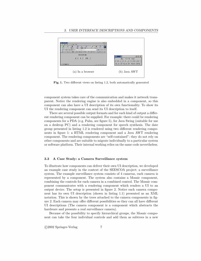
Fig. 1. Two different views on listing 1.2, both automatically generated
component system takes care of the communication and makes it network trans-parent. Notice the rendering engine is also embedded in a component, so thiscomponent can also have a UI description of its own functionality. To show itsUI the rendering component can send its UI description to itself.
There are several possible output formats and for each kind of output a differ-ent rendering component can be supplied. For example: there could be renderingcomponents for a PDA (e.g. Palm, see figure 5), for Java Swing (suitable for useon a desktop PC) and a rendering component for speech synthesis. The dategroup presented in listing 1.2 is rendered using two different rendering compo-nents in figure 1: a HTML rendering component and a Java AWT renderingcomponent. The rendering components are “self-contained”: they do not rely onother components and are suitable to migrate individually to a particular systemor software platform. Their internal working relies on the same code nevertheless.
3.3 A Case Study: a Camera Surveillance system
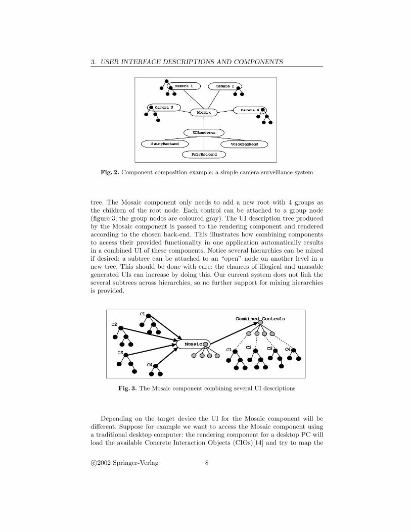
To illustrate how components can deliver their own UI description, we developedan example case study in the context of the SEESCOA project: a surveillancesystem. The example surveillance system consists of 4 cameras, each camera isrepresented by a component. The system also contains a Mosaic component,combining the controls for each camera in a combined control. The Mosaic com-ponent communicates with a rendering component which renders a UI to anoutput device. The setup is presented in figure 2. Notice each camera compo-nent has its own UI description (shown in listing 1.1) presented as an XMLnotation. This is shown by the trees attached to the camera components in fig-ure 2. Each camera may offer different possibilities so they can all have differentUI descriptions (The camera component is a component which abstracts thehardware and presents a real surveillance camera).
Because of the possibility to specify hierarchical groups, the Mosaic compo-nent can take the four individual controls and add them as subtrees in a new
c©2002 Springer-Verlag 7
3. USER INTERFACE DESCRIPTIONS AND COMPONENTS
Fig. 2. Component composition example: a simple camera surveillance system
tree. The Mosaic component only needs to add a new root with 4 groups asthe children of the root node. Each control can be attached to a group node(figure 3, the group nodes are coloured gray). The UI description tree producedby the Mosaic component is passed to the rendering component and renderedaccording to the chosen back-end. This illustrates how combining componentsto access their provided functionality in one application automatically resultsin a combined UI of these components. Notice several hierarchies can be mixedif desired: a subtree can be attached to an “open” node on another level in anew tree. This should be done with care: the chances of illogical and unusablegenerated UIs can increase by doing this. Our current system does not link theseveral subtrees across hierarchies, so no further support for mixing hierarchiesis provided.
Fig. 3. The Mosaic component combining several UI descriptions
Depending on the target device the UI for the Mosaic component will bedifferent. Suppose for example we want to access the Mosaic component usinga traditional desktop computer: the rendering component for a desktop PC willload the available Concrete Interaction Objects (CIOs)[14] and try to map the
c©2002 Springer-Verlag 8
3. USER INTERFACE DESCRIPTIONS AND COMPONENTS
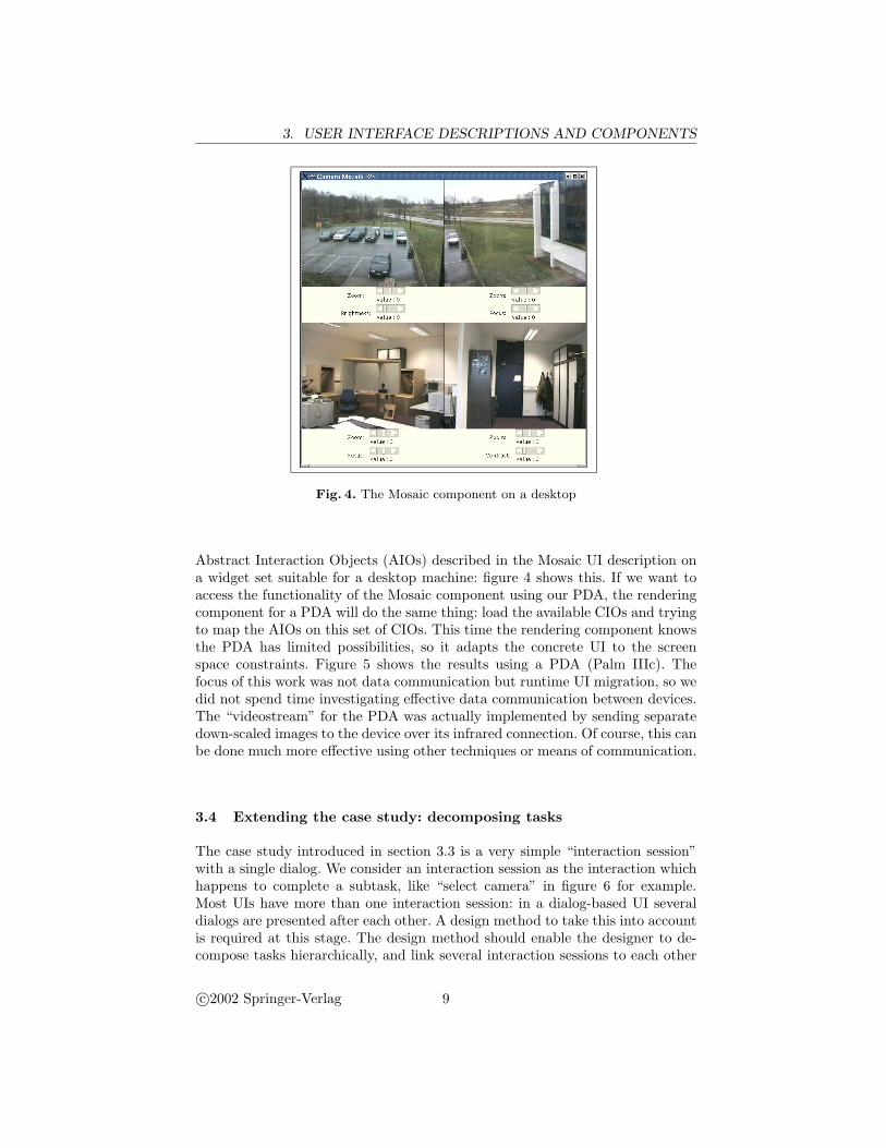
Fig. 4. The Mosaic component on a desktop
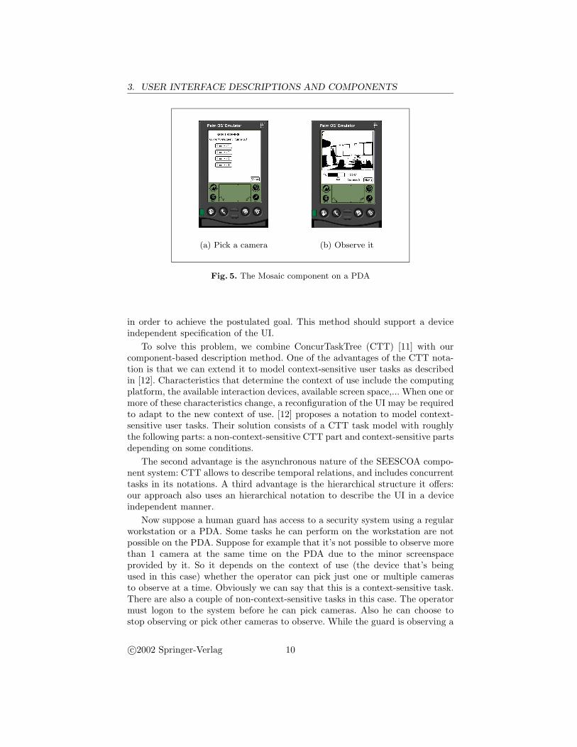
Abstract Interaction Objects (AIOs) described in the Mosaic UI description ona widget set suitable for a desktop machine: figure 4 shows this. If we want toaccess the functionality of the Mosaic component using our PDA, the renderingcomponent for a PDA will do the same thing: load the available CIOs and tryingto map the AIOs on this set of CIOs. This time the rendering component knowsthe PDA has limited possibilities, so it adapts the concrete UI to the screenspace constraints. Figure 5 shows the results using a PDA (Palm IIIc). Thefocus of this work was not data communication but runtime UI migration, so wedid not spend time investigating effective data communication between devices.The “videostream” for the PDA was actually implemented by sending separatedown-scaled images to the device over its infrared connection. Of course, this canbe done much more effective using other techniques or means of communication.
3.4 Extending the case study: decomposing tasks
The case study introduced in section 3.3 is a very simple “interaction session”with a single dialog. We consider an interaction session as the interaction whichhappens to complete a subtask, like “select camera” in figure 6 for example.Most UIs have more than one interaction session: in a dialog-based UI severaldialogs are presented after each other. A design method to take this into accountis required at this stage. The design method should enable the designer to de-compose tasks hierarchically, and link several interaction sessions to each other
c©2002 Springer-Verlag 9
3. USER INTERFACE DESCRIPTIONS AND COMPONENTS
(a) Pick a camera (b) Observe it
Fig. 5. The Mosaic component on a PDA
in order to achieve the postulated goal. This method should support a deviceindependent specification of the UI.
To solve this problem, we combine ConcurTaskTree (CTT) [11] with ourcomponent-based description method. One of the advantages of the CTT nota-tion is that we can extend it to model context-sensitive user tasks as describedin [12]. Characteristics that determine the context of use include the computingplatform, the available interaction devices, available screen space,... When one ormore of these characteristics change, a reconfiguration of the UI may be requiredto adapt to the new context of use. [12] proposes a notation to model context-sensitive user tasks. Their solution consists of a CTT task model with roughlythe following parts: a non-context-sensitive CTT part and context-sensitive partsdepending on some conditions.
The second advantage is the asynchronous nature of the SEESCOA compo-nent system: CTT allows to describe temporal relations, and includes concurrenttasks in its notations. A third advantage is the hierarchical structure it offers:our approach also uses an hierarchical notation to describe the UI in a deviceindependent manner.
Now suppose a human guard has access to a security system using a regularworkstation or a PDA. Some tasks he can perform on the workstation are notpossible on the PDA. Suppose for example that it’s not possible to observe morethan 1 camera at the same time on the PDA due to the minor screenspaceprovided by it. So it depends on the context of use (the device that’s beingused in this case) whether the operator can pick just one or multiple camerasto observe at a time. Obviously we can say that this is a context-sensitive task.There are also a couple of non-context-sensitive tasks in this case. The operatormust logon to the system before he can pick cameras. Also he can choose tostop observing or pick other cameras to observe. While the guard is observing a
c©2002 Springer-Verlag 10
3. USER INTERFACE DESCRIPTIONS AND COMPONENTS
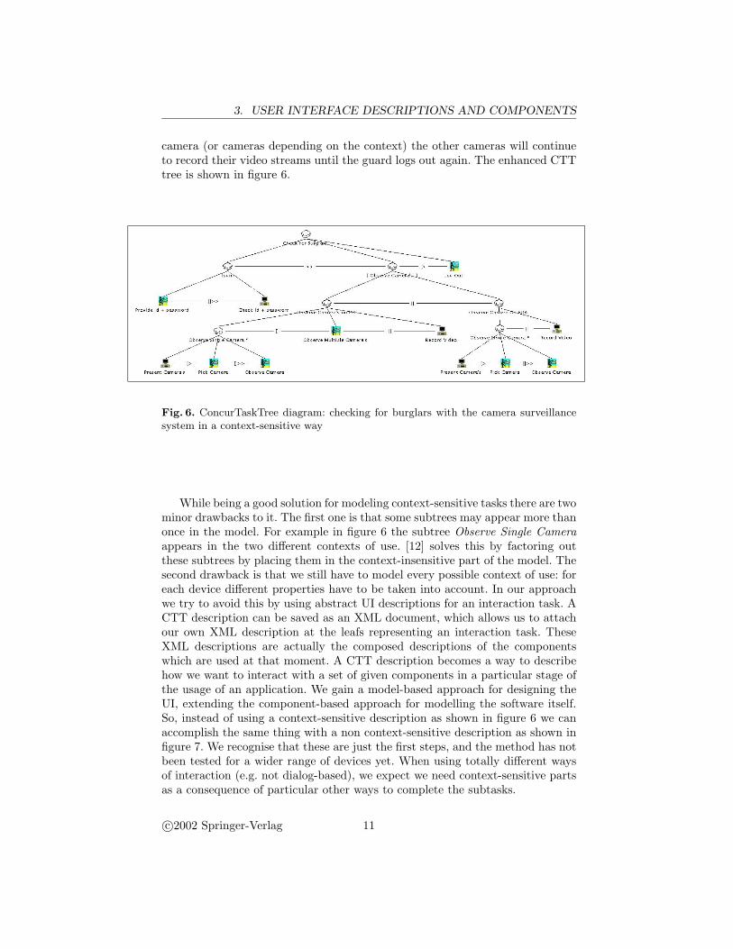
camera (or cameras depending on the context) the other cameras will continueto record their video streams until the guard logs out again. The enhanced CTTtree is shown in figure 6.
Fig. 6. ConcurTaskTree diagram: checking for burglars with the camera surveillancesystem in a context-sensitive way
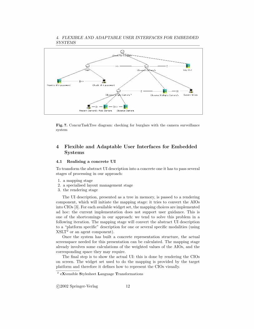
While being a good solution for modeling context-sensitive tasks there are twominor drawbacks to it. The first one is that some subtrees may appear more thanonce in the model. For example in figure 6 the subtree Observe Single Cameraappears in the two different contexts of use. [12] solves this by factoring outthese subtrees by placing them in the context-insensitive part of the model. Thesecond drawback is that we still have to model every possible context of use: foreach device different properties have to be taken into account. In our approachwe try to avoid this by using abstract UI descriptions for an interaction task. ACTT description can be saved as an XML document, which allows us to attachour own XML description at the leafs representing an interaction task. TheseXML descriptions are actually the composed descriptions of the componentswhich are used at that moment. A CTT description becomes a way to describehow we want to interact with a set of given components in a particular stage ofthe usage of an application. We gain a model-based approach for designing theUI, extending the component-based approach for modelling the software itself.So, instead of using a context-sensitive description as shown in figure 6 we canaccomplish the same thing with a non context-sensitive description as shown infigure 7. We recognise that these are just the first steps, and the method has notbeen tested for a wider range of devices yet. When using totally different waysof interaction (e.g. not dialog-based), we expect we need context-sensitive partsas a consequence of particular other ways to complete the subtasks.
c©2002 Springer-Verlag 11
4. FLEXIBLE AND ADAPTABLE USER INTERFACES FOR EMBEDDEDSYSTEMS
Fig. 7. ConcurTaskTree diagram: checking for burglars with the camera surveillancesystem
4 Flexible and Adaptable User Interfaces for EmbeddedSystems
4.1 Realising a concrete UI
To transform the abstract UI description into a concrete one it has to pass severalstages of processing in our approach:
1. a mapping stage2. a specialised layout management stage3. the rendering stage
The UI description, presented as a tree in memory, is passed to a renderingcomponent, which will initiate the mapping stage: it tries to convert the AIOsinto CIOs [3]. For each available widget set, the mapping choices are implementedad hoc: the current implementation does not support user guidance. This isone of the shortcomings in our approach: we tend to solve this problem in afollowing iteration. The mapping stage will convert the abstract UI descriptionto a “platform specific” description for one or several specific modalities (usingXSLT2 or an agent component).
Once the system has built a concrete representation structure, the actualscreenspace needed for this presentation can be calculated. The mapping stagealready involves some calculations of the weighted values of the AIOs, and thecorresponding space they may require.
The final step is to show the actual UI: this is done by rendering the CIOson screen. The widget set used to do the mapping is provided by the targetplatform and therefore it defines how to represent the CIOs visually.2 eXtensible Stylesheet Language Transformations
c©2002 Springer-Verlag 12
5. SUMMARY OF OUR CURRENT RESULTS
4.2 System independent User Interfaces
Every time a new device is used as output device, the specific UI renderer com-ponent will use the device profile, containing the device constraints and its adhoc knowledge of the target system. The renderer changes the UI presentationaccording to the defined limitations.
One of the consequences of adapting the UI to new device constraints is theneed for an automatic layout algorithm when GUI rendering is used. When theUI moves to a new output device, the UI should be laid out in a logical way. Oneapproach achieving this is by using layout algorithms found in diagram rendering(like graphs and state-charts). Due to the hierarchical view on the UI, we tryto adopt weighting algorithms especially designed for presenting as hierarchicaldata like presented in [4]. Every leaf is given a weight indicating its complexity(primarily space needs). Recursively every group (i.e. every node that is no leaf)will get the complexity of its children and is added up with a certain constantvalue in complexity weight. This is a simple attempt to automate the layoutalgorithm, without taking into account real usability issues which arise whenautomating this process.
Our architecture allows each subtree of a UI description tree to use a differentlayout algorithm. For example; we use a layout algorithm that allocates spacefrom left to right in a rectangular space for the first level of subtrees underthe root node. The space is allocated according to the weighted complexity ofeach subtree. On the next level, a more complex layout algorithm is used (like aGridBagLayout in the Java programming language) for each subtree. One of theadvantages of this approach is a better support for fragmented UI (several partsof the UI are accessible from several devices), multi-modal UIs and dynamicallychanging UIs. Currently we are integrating spatial constraints for 2D UI in oursystem, so the UI designer can indicate how AIOs should be placed in relationto each other [7].
5 Summary of our Current Results
Current results include a rendering component, to which an XML document de-scribing an abstracted UI can be submitted. The renderer maps this descriptionto an actual widget set and tries to adapt the layout so the UI fits on screen.When the screen size becomes too small, the renderer will try to split differentparts of the UI and put them behind each other. While doing this, logicallygrouped elements will not be split up. These grouping operators are specifiedin the abstract UI description: they group user interactions which logically de-pend on each other. Examples of tested target widget sets are Java AWT, Swing,kAWT and HTML (web pages).
The SEESCOA Components can be combined in order to make a fully func-tional application and their UI description can be combined automatically. Anexample of this was described using the Camera Mosaic application. This en-ables User Interfaces to become migratable: first of all their description can be
c©2002 Springer-Verlag 13
6. CONCLUSIONS AND FUTURE WORK
rendered to other output devices and second the UI can accompany the compo-nent it represents when it is sent to another system. We have only tested thesystem with simple UIs, so no conclusions can be made concerning scalability.
6 Conclusions and Future Work
The new component-oriented approach suggested in this paper has several ad-vantages for developers of embedded systems and mobile computing devices inparticular. It is
Flexible : changing the UI can be done by another renderer component orletting components provide another UI description;
Reusable : providing a high level description of the UI related to the function-ality a component offers, allows easier reusability of previously designed UIsin contrast with hard-coded UIs;
Adaptable : by abstracting the UI, device constraints can be taken into accountwhen rendering the concrete UI.
Besides these advantages we showed how attaching abstract UI descriptions tocomponents helps to compose User Interfaces at runtime without interventionfrom a programmer. This is especially important when a mobile computing de-vice has to present a new service that it was not aware of. E.g. a PDA comesnear to a printer and should be able to present the accessible functionality ofthis printer. All these advantages make the UIs migratable: they can be easilytransported from one device to another, adapting to new environments.
Future work includes adding alternative output rendering components otherthen a 2D screen renderer like speech output and the implementation of context-sensitive layout algorithms. We acknowledge there is a lack of support for artisticand aesthetic influences in the creation of the UIs employing the approach wepresented in this paper. It is our intention to look at alternative interactionmethods besides traditional interaction methods. Due to the asynchronous na-ture of the SEESCOA component system, it is interesting to take time-relatedHCI patterns into account.
Although the focus is not on the usability of the UIs, introducing these pat-terns can help us to ensure a minimal usability. For introducing design-time typechecks an appropriate editor for this is required. Some checks can be done if acertain amount of information of the application logic is available (the editorshould know which arguments can be handled by what kind of functionality).An editor for designing the UI descriptions is not available at this moment.
7 Acknowledgements
Our research is partly funded by the Flemish government and EFRO3. TheSEESCOA project IWT 980374 is directly funded by the IWT4. The Vrije Uni-3 European Fund for Regional Development4 Flemish subsidy organization
c©2002 Springer-Verlag 14
7. ACKNOWLEDGEMENTS
versiteit Brussel (Programming Lab) and Katholieke Universiteit Leuven (Dis-trinet) have created the SEESCOA component system.
References
1. Marc Abrams, Constantinos Phanouriou, Alan L. Batongbacal, Stephen M.Williams, and Jonathan E. Shuster. UIML: An Appliance-Independent XMLUser Interface Language. World Wide Web, http://www8.org/w8-papers/
5b-hypertext-media/uiml/uiml.html, 1998.2. Marc Abrams, Constantinos Phanouriou, Alan L. Batongbacal, Stephen M.
Williams, and Jonathan E. Shuster. UIML: An appliance-independent XML userinterface language. WWW8 / Computer Networks, 31(11-16):1695–1708, 1999.
3. Jacob Eisenstein, Jean Vanderdonckt, and Angel Puerta. Applying Model-BasedTechniques to the Development of UIs for Mobile Computers. In IUI 2001 Inter-national Conference on Intelligent User Interfaces, pages 69–76, 2001.
4. David Harel and Gregory Yashchin. An Algorithm for Blob Hierarchy Layout.In Proceedings of the Working Conference on Advanced Visual Interfaces, pages29–40, May 2000.
5. Elliotte Rusty Harold. XML; Extensible Markup Language, Structuring ComplexContent for the Web. IDG Books Worldwide, 1998.
6. IBM Corporation. MoDAL (Mobile Document Application Language). World WideWeb, http://www.almaden.ibm.com/cs/TSpaces/MoDAL/.
7. Simon Lok and Steven Feiner. A Survey of Automated Layout Techniques forInformation Presentations. In Proceedings of SmartGraphics 2001, March 2001.
8. Kris Luyten and Karin Coninx. An XML-based runtime user interface descriptionlanguage for mobile computing devices. In Proceedings of the Eight Workshop ofDesign, Specification and Verification of Interactive Systems, pages 17–29, June2001.
9. Andreas Mulller, Peter Forbrig, and Clemens Cap. Model-Based User InterfaceDesign Using Markup Concepts. In Proceedings of the Eight Workshop of Design,Specification and Verification of Interactive Systems, pages 30–39, June 2001.
10. Dan R. Olsen, Sean Jefferies, Travis Nielsen, William Moyes, and Paul Fredrickson.Cross-modal interaction using XWeb. In Proceedings of the 13th Annual Sympo-sium on User Interface Software and Technology (UIST-00), pages 191–200, N.Y.,November 5–8 2000. ACM Press.
11. Fabio Paterno. Model-Based Design and Evaluation of Interactive Applications.Springer, 2000.
12. Costin Pribeanu, Quentin Limbourg, and Jean Vanderdonckt. Task Modelling forContext-Sensitive User Interfaces. In Proceedings of the Eight Workshop of Design,Specification and Verification of Interactive Systems, pages 60–76, June 2001.
13. David Urting, Stefan Van Baelen, Tom Holvoet, and Yolande Berbers. EmbeddedSoftware Development: Components and Contracts. In Proceedings of the IASTEDInternational Conference Parallel and Distributed Computing and Systems, pages685–690, 2001.
14. J. Vanderdonckt and F. Bodart. Encapsulating knowledge for intelligent automaticinteraction objects selection. In ACM Conference on Human Aspects in ComputingSystems InterCHI’93, pages 424–429. Addison Wesley, 1993.
c©2002 Springer-Verlag 15