Embed Size (px)
Citation preview
Page 1
RXT150P
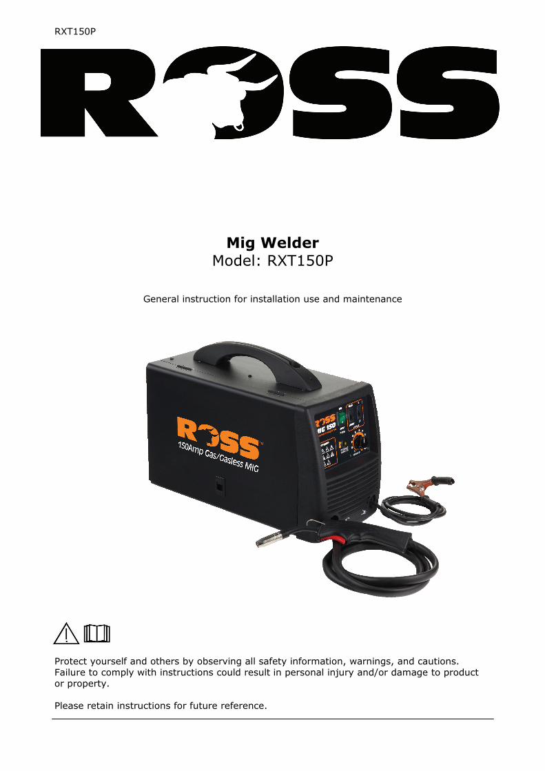
Protect yourself and others by observing all safety information, warnings, and cautions. Failure to comply with instructions could result in personal injury and/or damage to product or property. Please retain instructions for future reference.
Mig Welder Model: RXT150P
General instruction for installation use and maintenance
Page 2
RXT150P
IMPORTANT Please read all of the safety and operating instructions carefully before using this product. Please pay particular attention to all sections of this manual that carry warning symbols and notices.
WARNING! This is a Warning symbol. This symbol is used throughout the manual whenever there is a risk of personal injury. Ensure that these warnings are read and under-stood at all times.
CAUTION! This is a Caution symbol. This symbol is used throughout the user guide when-ever there is a risk of damaging your product. Ensure that these warnings are read and understood at all times.
GENERAL DESCRIPTION This welder is a power source for light duty manual arc welding only. It has been designed and manufactured specifically for continuous MIG welding of carbon or mild steels with and without protective gas using appropriate cored (tubular) electrode wire or solid wire. Power for the arc is given by a single phase transformer with a drooping characteristic. It is suitable for use with 0.6mm solid or 0.8/0.9mm cored wire and for welding materials up to 6mm.
PRODUCT SPECIFICATION
Note: This unit is suitable for connection to standard domestic 10 Amp power outlet.
Item RXT150P
Input Power V 230
Frequency Hz 50
Phase No. 1
Rated No-load Voltage V 33 V DC
Rated Input Capacity KVA 4.8 KVA
Rated Duty Cycle % 10
Output current A 35-115A — Peak 150A
Insulation Grade H
Cooling Type Fan Cooled
Case Protection Class IP21S ,not suitable for storage or use in rain
External Dimension: L x W x H cm 49cm x 24cm x 37cm
Weight kg 20kg
Page 3
RXT150P
The user of this welder is responsible for his own and the safety of others. It is most impor-tant to read, learn and respect the rules in this user guide. When using this welder, basic safety precautions, including the following, should be followed to reduce the risk of fire, electric shock and personal injury. Make sure that you have read all of these instructions before using this welder. Keep this booklet in a safe place for future ref-erence. Persons who are not familiar with this booklet should not use the welder.
TRAINING The operator should be properly trained to use the welding machine safely and should be in-formed about the risks relating to arc welding procedures. This manual does not attempt to cover welding technique. Training should be sought from qualified/experienced personnel on this aspect especially for any welds requiring high integrity for safety.
SERIOUS FIRE RISK The welding process produces sparks, droplets of fused metal, metal projectiles and fumes. This constitutes a serious fire risk. Make sure that the area around the work piece is clear of all inflammable materials. It is advisable to have a fire extinguisher to hand.
WORK AREA Ensure a clear work area with unrestricted movement for the operator. Always maintain easy access to the On/Off switch and the mains supply.
THE WORK PIECE The work piece will remain at a high temperature for a relatively long period. Do not touch the weld or the work piece unless you are wearing welding gloves. Always use pliers or tongs. Never touch the welded material with bare hands until it has been allowed to cool.
WARNING! SAFETY INSTRUCTIONS
VENTILATE THE WORK AREA Arc welding (especially using fluxed core wire) emits fumes which can be dangerous. Make sure that the work area is well ventilated.
WELDING SURFACES Do not weld on containers or pipes that hold, or have held, flammable liquids or com-
bustible gases. Do not weld coated, painted or varnished surfaces as the coatings may ignite and or can
give off dangerous fumes.
CONSIDER WORK AREA ENVIRONMENT Do not expose the welder to rain. Do not use it in damp, or wet locations. Keep the work area well lit.
AVOID ELECTRICAL CONTACT Use adequate electrical insulation with regard to the electrode, the work piece and any acces-sible) earthed metal parts in the vicinity. Avoid direct contact with the welding circuit. The no load voltage between the earth clamp and the torch can be dangerous under certain circum-stances.
EXTENSION LEADS In general these are best avoided. If used however make sure that the extension lead used with the welder is of a suitable current rating and has an earth connection. If using the welder outdoors make sure that the extension cable is suitable for outdoor use. Always keep cables and extension leads away from the welding zone and any hot materials.
FOR ADDITIONAL PROTECTION FROM ELECTRIC SHOCK It is recommended that this tool be used in conjunction with a residual current device (RCD) with a rated residual current of 30mA or less.
Page 4
RXT150P
SAFETY INSTRUCTIONS … cont
CHECK DAMAGED PARTS Before further use of the welder, any part that is damaged should be carefully checked to de-termine that it will operate properly and perform its intended function. Check for breakage of parts and any other conditions that may affect its operation. Any part that is damaged should be properly repaired, or replaced, by an authorised service centre.
ALWAYS USE THE WELDING MASK Under no circumstances should the welder be operated unless the welding mask is protecting the eyes and face. There is a serious risk of eye damage if the mask is not used. The sparks and metal projectiles can cause serious damage to the eyes and face. The light radiation pro-duced by the arc can cause damage to eyesight and burns on the skin. Never remove the welding mask whilst welding. Move the torch away from the work piece and release the trig-ger switch before removing the welding mask.
SAFETY GLASSES After welding use safety glasses when brushing, chipping grinding the slag from the weld.
OTHER PERSONS Ensure that other persons are screened from the welding arc and are at least 15 metres away from the work piece. Always ensure that the welding arc is screened from onlookers, or peo-ple just passing by. Use screens if necessary, or non reflecting curtains.
KEEP CHILDREN AND ANIMALS AWAY Do not let children or animals have access to the welding equipment or to the work area.
SWITCHING OFF When you have finished welding switch off the welder. Do not put the torch down with the welder switch On and with the wire fitted. When leaving the welder unattended, move the On/Off switch to the Off position and disconnect the welder from the mains supply. Do not leave hot material unattended after welding.
WELDING CABLES Keep the welding cables, earth clamp and torch in good condition. Failure to can result in poor welding quality and could be dangerous in structural situations.
DRESS PROPERLY Use protective gloves and fire resistant protective clothing when using the welder. Avoid ex-posing skin to the ultraviolet rays produced by the arc.
CAUTION! VENTILATE THE WELDER There must always be a sufficient air passage around the welder to allow for the cooling of the transformer. If the cooling process is obstructed the welder will over-heat and the overload cut out protector will activate and cut off the welding current. If the overload cut out protector activates leave the welder for at least 15 minutes
to cool down before further use.
IMPROPER USE Do not use this welder for pipe thawing.
HANDLING Ensure the handle is correctly fitted and always use safe lifting practices when lifting.
Page 5
RXT150P
ADDITIONAL PRECAUTIONS
WELDING OPERATIONS: In environments with increased risk of electric shock; In confined spaces; In the presence of flammable or explosive materials; MUST BE evaluated in advance by an “expert supervisor” and must always be carried out in the presence of other people trained to intervene in emergencies. POSITION and HANDLING Position the welding machine on a horizontal surface that is able to support the weight: otherwise (e.g. inclined or uneven floors etc.) there is danger of over-turning. The welder MUST NOT be supported by the operator (e.g using belts). The operator MUST NOT BE ALLOWED to weld in raised positions unless safety platforms are used. VOLTAGE BETWEEN ELECTRODE HOLDERS OR TORCHES: Working with more than one welding machine on a single piece or on pieces that are connected may generate a dangerous accumulation of no-load voltage be-tween two different electrode holders or torches, the value of which may reach double the allowed limit.
IMPROPER USE: It is hazardous to use the welding machine for any work other than that for which it was designed. Example do not use this welder for pipe thawing. The safety guards and moving parts of the covering of the welding machine and of the wire feeder should be in their proper positions before connecting the welding machine to the power supply. WARNING! Any manual operation carried out on the moving parts of the wire feeder, for example: Replacing rollers and/or the wire guide; Inserting wire in the rollers; Loading the wire reel; Cleaning the rollers and the area underneath them. Should be carried out with the welding machine switched off and disconnected from the power supply outlet . Never lift the welding machine when connected to the mains supply.
Page 6
RXT150P
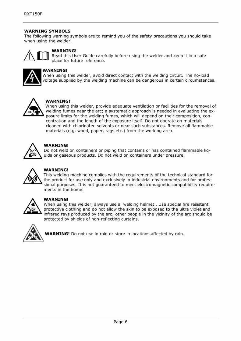
WARNING SYMBOLS The following warning symbols are to remind you of the safety precautions you should take when using the welder.
WARNING! Read this User Guide carefully before using the welder and keep it in a safe place for future reference.
WARNING! When using this welder, avoid direct contact with the welding circuit. The no-load voltage supplied by the welding machine can be dangerous in certain circumstances.
WARNING! When using this welder, provide adequate ventilation or facilities for the removal of welding fumes near the arc; a systematic approach is needed in evaluating the ex-posure limits for the welding fumes, which will depend on their composition, con-centration and the length of the exposure itself. Do not operate on materials cleaned with chlorinated solvents or near such substances. Remove all flammable materials (e.g. wood, paper, rags etc.) from the working area.
WARNING! Do not weld on containers or piping that contains or has contained flammable liq-uids or gaseous products. Do not weld on containers under pressure. WARNING! This welding machine complies with the requirements of the technical standard for the product for use only and exclusively in industrial environments and for profes-sional purposes. It is not guaranteed to meet electromagnetic compatibility require-ments in the home. WARNING! When using this welder, always use a welding helmet . Use special fire resistant protective clothing and do not allow the skin to be exposed to the ultra violet and infrared rays produced by the arc; other people in the vicinity of the arc should be protected by shields of non-reflecting curtains. WARNING! Do not use in rain or store in locations affected by rain.
Page 7
RXT150P
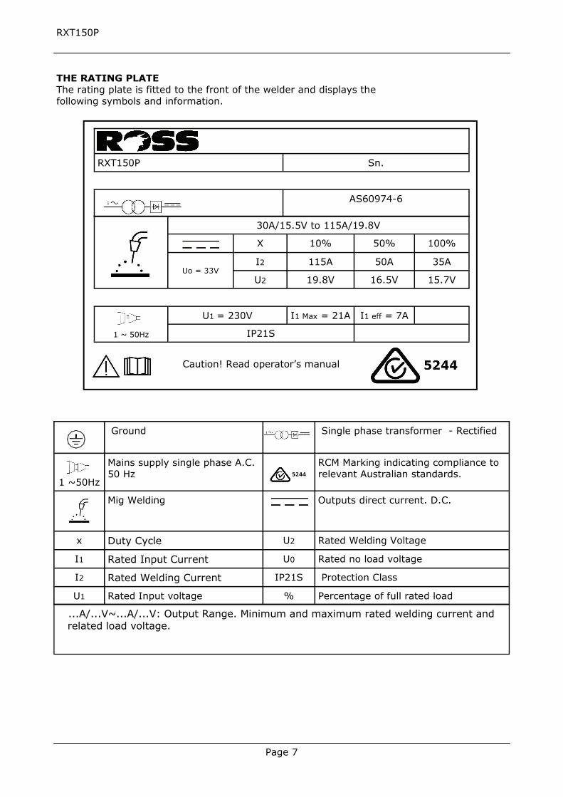
THE RATING PLATE The rating plate is fitted to the front of the welder and displays the following symbols and information.
30A/15.5V to 115A/19.8V
X 10% 50% 100%
I2 115A 50A 35A
U2 19.8V 16.5V 15.7V
1 ~ 50Hz
U1 = 230V I1 Max = 21A I1 eff = 7A
IP21S
Uo = 33V
RXT150P
AS60974-6
Sn.
Caution! Read operator’s manual
Ground Single phase transformer - Rectified
1 ~50Hz
Mains supply single phase A.C. 50 Hz
RCM Marking indicating compliance to relevant Australian standards.
Mig Welding Outputs direct current. D.C.
x Duty Cycle U2 Rated Welding Voltage
I1 Rated Input Current U0 Rated no load voltage
I2 Rated Welding Current IP21S Protection Class
U1 Rated Input voltage % Percentage of full rated load
...A/...V~...A/...V: Output Range. Minimum and maximum rated welding current and related load voltage.
Page 8
RXT150P
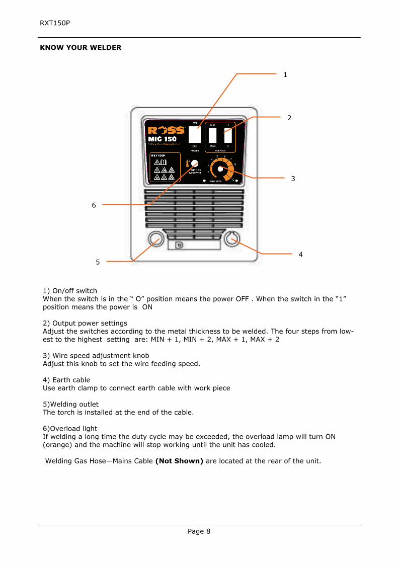
1) On/off switch When the switch is in the “ O” position means the power OFF . When the switch in the “1” position means the power is ON 2) Output power settings Adjust the switches according to the metal thickness to be welded. The four steps from low-est to the highest setting are: MIN + 1, MIN + 2, MAX + 1, MAX + 2 3) Wire speed adjustment knob Adjust this knob to set the wire feeding speed. 4) Earth cable Use earth clamp to connect earth cable with work piece 5)Welding outlet The torch is installed at the end of the cable. 6)Overload light If welding a long time the duty cycle may be exceeded, the overload lamp will turn ON(orange) and the machine will stop working until the unit has cooled. Welding Gas Hose—Mains Cable (Not Shown) are located at the rear of the unit.
KNOW YOUR WELDER
1
2
3
4 5
6
Page 9
RXT150P
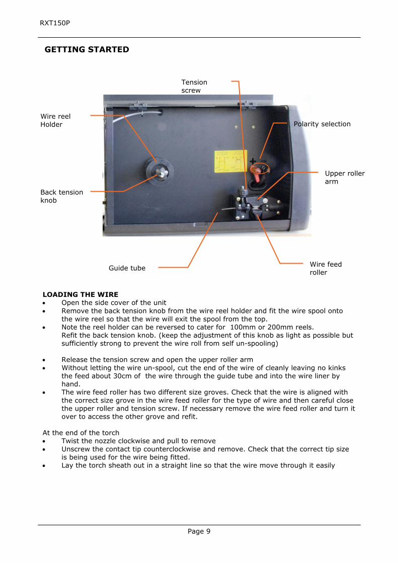
Wire reel Holder
Back tension knob
Tension screw
Wire feed roller
GETTING STARTED
Upper roller arm
Guide tube
Polarity selection
LOADING THE WIRE Open the side cover of the unit Remove the back tension knob from the wire reel holder and fit the wire spool onto
the wire reel so that the wire will exit the spool from the top. Note the reel holder can be reversed to cater for 100mm or 200mm reels.
Refit the back tension knob. (keep the adjustment of this knob as light as possible but sufficiently strong to prevent the wire roll from self un-spooling)
Release the tension screw and open the upper roller arm Without letting the wire un-spool, cut the end of the wire of cleanly leaving no kinks
the feed about 30cm of the wire through the guide tube and into the wire liner by hand.
The wire feed roller has two different size groves. Check that the wire is aligned with the correct size grove in the wire feed roller for the type of wire and then careful close the upper roller and tension screw. If necessary remove the wire feed roller and turn it over to access the other grove and refit.
At the end of the torch Twist the nozzle clockwise and pull to remove Unscrew the contact tip counterclockwise and remove. Check that the correct tip size
is being used for the wire being fitted. Lay the torch sheath out in a straight line so that the wire move through it easily
Page 10
RXT150P
To commence the welding process proceed as follows. Make sure that the earth clamp is firmly connected to the Work piece. WARNING! Ensure that you have your protective clothes, gloves and welding helmet cor-rectly fitted before welding. Do not start welding before your eyes are properly protected by the welding helmet.
Turn the welder switched ON and the welding gas if applicable. You are now ready to execute the weld. Select the required welding power setting weld. Bring the wire into close proximity of the required weld start position. Keep the tip ap-
proximately 10-15 mm away from the work piece and squeeze the trigger on the torch to commence welding.
Adjust the wire feed rate to obtain the optimum weld Caution! (Do not adjust the welding power setting while welding)
Release the trigger to stop welding. When finished welding turn the welder off and the welding gas if applicable. Allow the weld to cool, the slag can be removed by tapping it lightly with the chipping
hammer/wire brush. Always wear safety glasses when brushing or chipping slag from the weld.
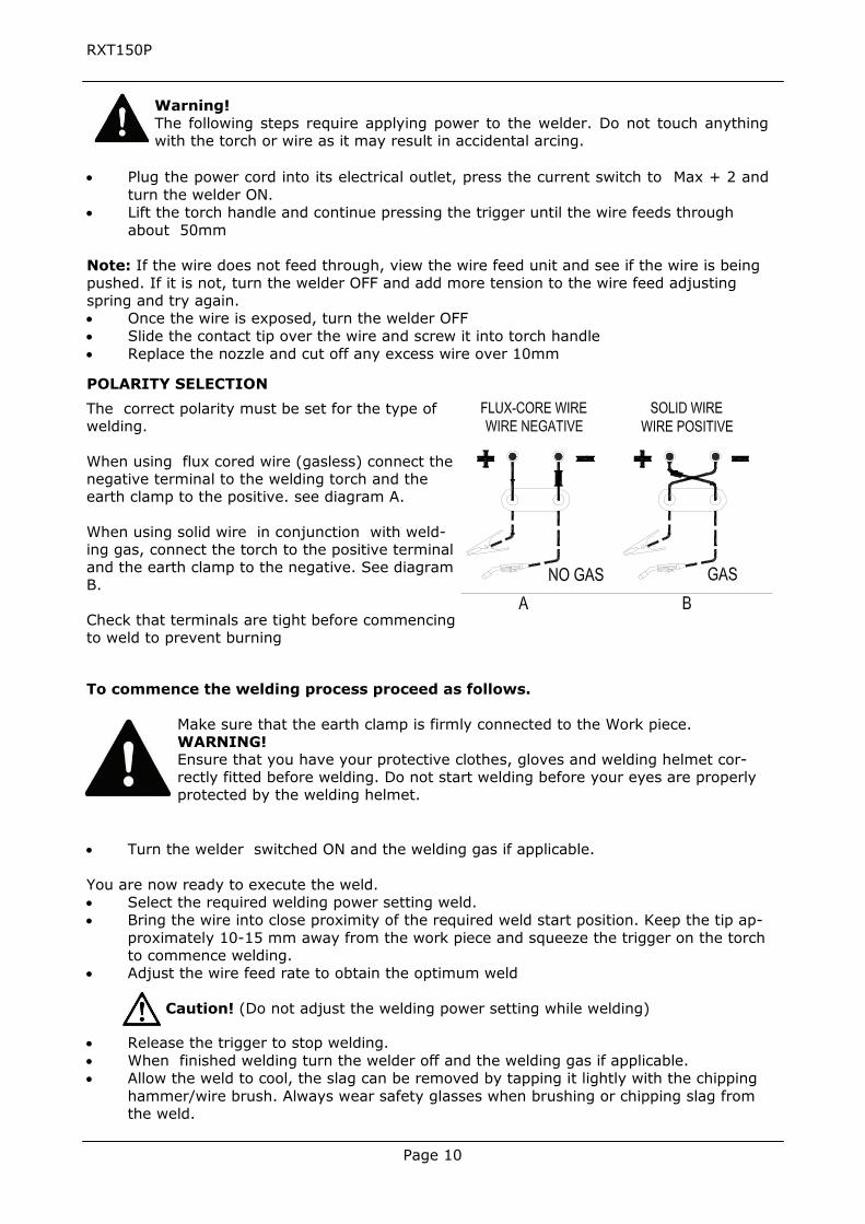
POLARITY SELECTION
The correct polarity must be set for the type of welding. When using flux cored wire (gasless) connect the negative terminal to the welding torch and the earth clamp to the positive. see diagram A. When using solid wire in conjunction with weld-ing gas, connect the torch to the positive terminal and the earth clamp to the negative. See diagram B. Check that terminals are tight before commencing to weld to prevent burning
Warning! The following steps require applying power to the welder. Do not touch anything with the torch or wire as it may result in accidental arcing.
Plug the power cord into its electrical outlet, press the current switch to Max + 2 and
turn the welder ON. Lift the torch handle and continue pressing the trigger until the wire feeds through
about 50mm
Note: If the wire does not feed through, view the wire feed unit and see if the wire is being pushed. If it is not, turn the welder OFF and add more tension to the wire feed adjusting spring and try again. Once the wire is exposed, turn the welder OFF Slide the contact tip over the wire and screw it into torch handle Replace the nozzle and cut off any excess wire over 10mm
Page 11
RXT150P
THERMOSTATIC PROTECTION This welder is automatically protected from overheating by a thermal overload cut out protec-tor. If the transformer overheats the overload cut out protector will activate and cut off. The amber light will illuminate to show that the cut out has operated. After cooling the protector will reconnect the supply circuit and the welder will be ready for further use. NOTE: If the duty cycle of the machine is exceeded the thermostatic protection will activate.
MAINTENANCE
WARNING! Before starting any cleaning, or maintenance procedures on the welding machine, make sure that it is switched Off and disconnected from the mains supply.
There are no user serviceable parts inside the welder. Refer to qualified service personnel if any internal maintenance is required.
Switch off the welding machine and disconnect it from the power supply before replacing con-sumable torch parts. Allow to cool before handling. After use, allow the welder to cool down and then remove any unconsumed wire from the torch and torch hose by releasing the tension screw and rotating the reel in an anti-clockwise direction.
TORCH Do not put the torch or its cable on hot work pieces; this would cause the insulating materials to melt, making the torch unusable. Every time the wire reel is changed, clean out the wire-guide and check the wire liner for build up of dust and other contaminants. This increases friction and can lead to erratic wire feed and jamming. Replace when necessary. Daily: Check the wear and correct assembly of the consumable parts at the end of the torch; swan neck, nozzle, contact tip. Replace when necessary.
WIRE FEEDER Make frequent checks on the state of wear of the wire feed rollers, regularly remove the metal dust deposited in the feeder area (rollers and wire-guide in-feed and out- feed)
OTHER Make sure that the earth clamp is kept clean and in good working order. Keep the cooling vents clear and clean the outer casing with a soft cloth.
Page 12
RXT150P
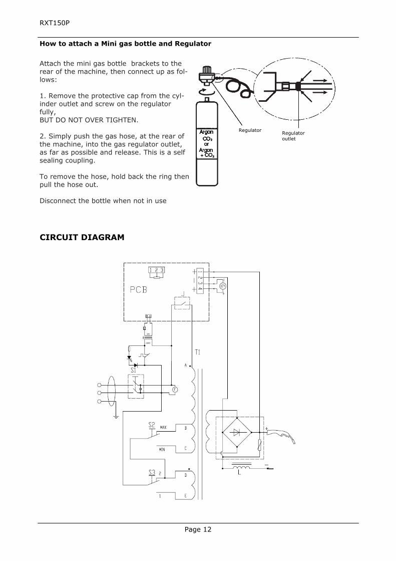
CIRCUIT DIAGRAM
Attach the mini gas bottle brackets to the rear of the machine, then connect up as fol-lows: 1. Remove the protective cap from the cyl-inder outlet and screw on the regulator fully, BUT DO NOT OVER TIGHTEN. 2. Simply push the gas hose, at the rear of the machine, into the gas regulator outlet, as far as possible and release. This is a self sealing coupling. To remove the hose, hold back the ring then pull the hose out. Disconnect the bottle when not in use
Regulator Regulator outlet
How to attach a Mini gas bottle and Regulator
Page 13
RXT150P
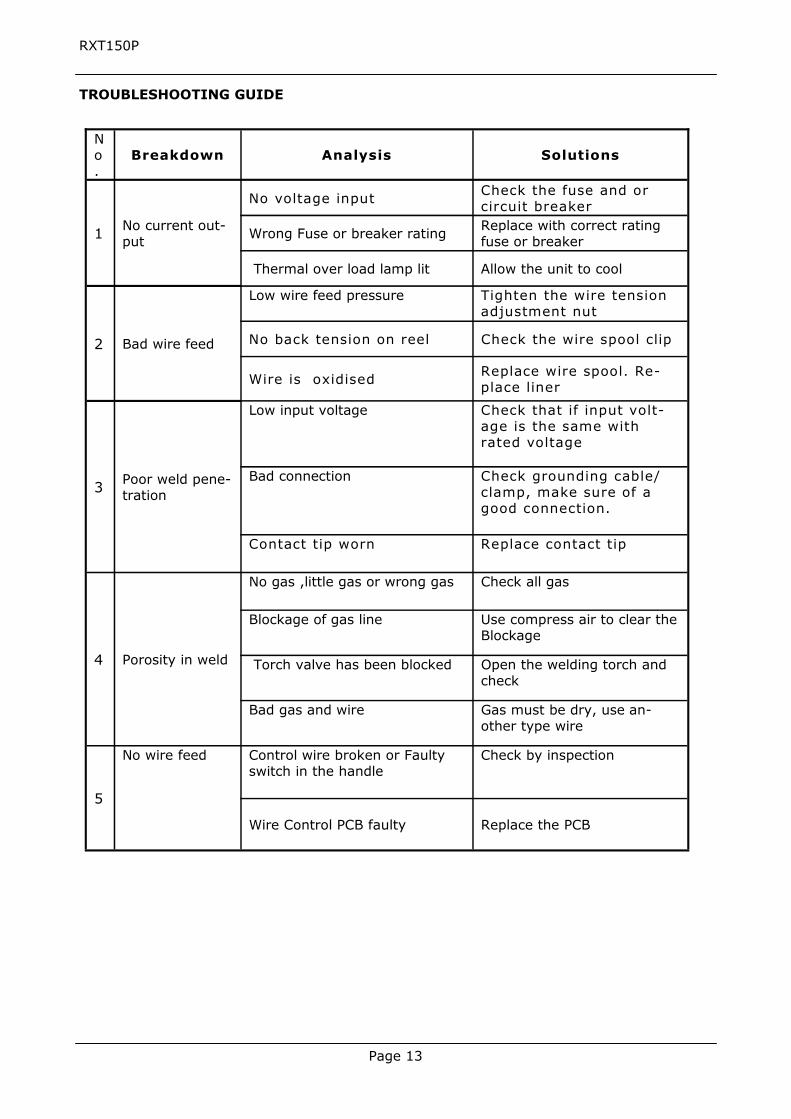
No.
Breakdown Analysis Solutions
1 No current out-put
No voltage input Check the fuse and or circuit breaker
Wrong Fuse or breaker rating Replace with correct rating fuse or breaker
Thermal over load lamp lit Allow the unit to cool
2 Bad wire feed
Low wire feed pressure Tighten the wire tension adjustment nut
No back tension on reel Check the wire spool clip
Wire is oxidised Replace wire spool. Re-place liner
3 Poor weld pene-tration
Low input voltage Check that if input volt-age is the same with rated voltage
Bad connection Check grounding cable/ clamp, make sure of a good connection.
Contact tip worn Replace contact tip
4 Porosity in weld
No gas ,little gas or wrong gas Check all gas
Blockage of gas line Use compress air to clear the Blockage
Torch valve has been blocked Open the welding torch and check
Bad gas and wire Gas must be dry, use an-other type wire
5
No wire feed Control wire broken or Faulty switch in the handle
Check by inspection
Wire Control PCB faulty Replace the PCB
TROUBLESHOOTING GUIDE
Page 14
RXT150P
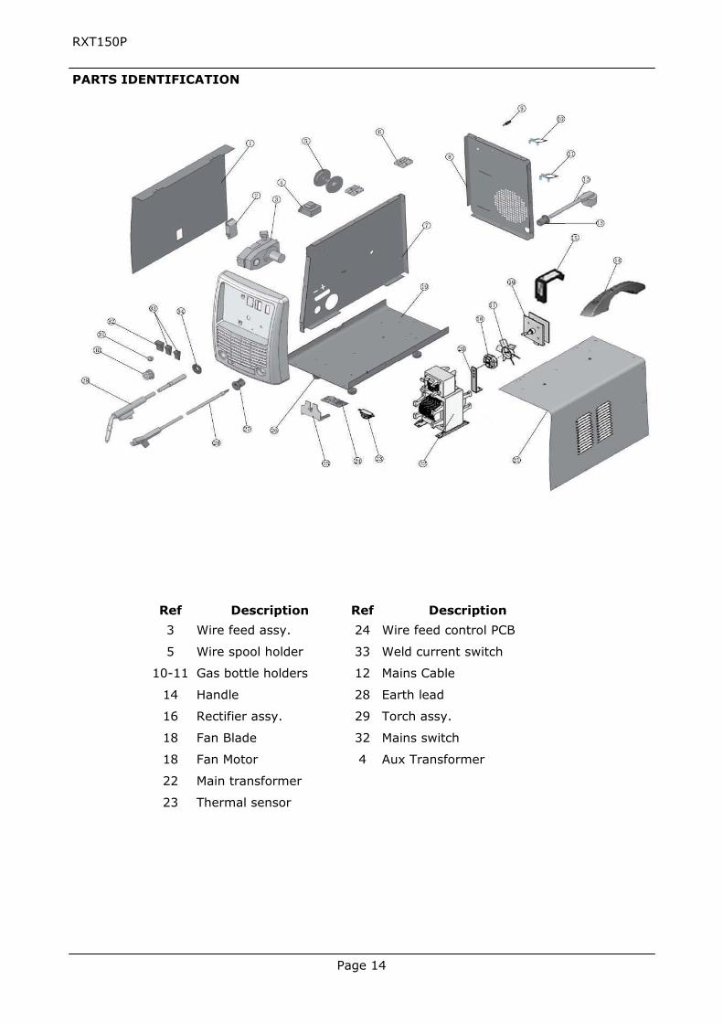
Ref Description Ref Description
3 Wire feed assy. 24 Wire feed control PCB
5 Wire spool holder 33 Weld current switch
10-11 Gas bottle holders 12 Mains Cable
14 Handle 28 Earth lead
16 Rectifier assy. 29 Torch assy.
18 Fan Blade 32 Mains switch
18 Fan Motor 4 Aux Transformer
22 Main transformer
23 Thermal sensor
PARTS IDENTIFICATION
Page 15
RXT150P
WARRANTY: This product has been manufactured to a high quality standard. It is guaranteed against faulty materials and workmanship for 12 months from the date of purchase. Please retain your receipt as proof of purchase. If the product is found to be defective within the relevant time period, we will either replace all defective parts or, at our discretion, replace the unit free of charge. This guarantee does not cover defects caused by or resulting from: misuse, abuse or ne-glect; trade, professional or hire use; repairs attempted by anyone other than our authorised service agent; or damage caused by foreign objects, substances or accident. Note: Consumable items such as swan necks, nozzles, contacts tips, wire liners etc are not covered by warranty.
Distributed in Australia by J W Ross and Sons ( Australia ) Pty Ltd.
PO Box 352 North Ryde BC, NSW, 1670 Inquiries phone 1800 251 338