Embed Size (px)
Citation preview
OPERATING MANUAL
MIG POWER SOURCE Model Description Plant Power Source
TRANSMIG 220 710024 710025 (Single Phase)
TRANSMIG 250 710018 710019 (Single Phase)
TRANSMIG 253 710009 710013 (Three Phase)
PART NO. ISSUE DATE
719454 02 403


Manufacturer and Merchandiser of Quality Consumables and Equipment: CIGWELD
Head Office Address: 71 Gower St, Preston
Victoria 3072
Australia
Description of equipment: Welding Equipment (Mig/Mag). CIGWELD Transmig 220, 250, 253 and associated accessories.
* Serial numbers are unique with each individual piece of equipment and details description, parts used to manufacture a unit and date of manufacture.
National Standard and Technical Specifications
The product(s) are guided in design to a number of standards and technical requirements as listed below:
* AS1966-1 relevant clauses applicable to welding equipment and associated accessories.
* AS/NZS 3195:1995 relevant clauses applicable to portable machines for electric arc welding and allied processes.
* AS/NZS 3652-(EMC Directive EN50199) applicable to arc welding equipment –generic emissions and regulations.
* AS1939-1990 relevant clauses applicable to degree of protection provided by enclosures for electrical equipment IP21
* Extensive product design verification is conducted at the manufacturing facility as part of the routine design and manufacturing process, to ensure the product is safe and performs as specified. Rigorous testing is incorporated into the manufacturing process to ensure the manufactured product meets or exceeds all design specifications.
CIGWELD has been manufacturing and merchandising extensive equipment range with superior performance, ultra safe operation and world class quality for more than 30 years and will continue to achieve excellence.

Transmigs 220, 250 & 253
- i -
Table Of Contents Page
1 Unpacking Your Transmig.........................................................................................................1
2 Rear Wheel Assembly ...............................................................................................................1
3 Front Swivel Castors And Cylinder Tray Assembly ..............................................................1
4 Rear Cylinder Bracket Assembly .............................................................................................2
5 Introduction ..................................................................................................................................2
6 Electromagnetic Compatibility ..................................................................................................6
7 Electromagnetic Compatibility - Methods Of Reducing Emissions.....................................7
8 General Information ...................................................................................................................8
9 Safe Practices For The Use Of Welding Equipment...........................................................10
10 Resuscitation For Electric Shock Victims .............................................................................11
11 Specifications ............................................................................................................................13
12 Installation Recommendations ...............................................................................................16
13 Set Up For Compact Transmig...............................................................................................18
14 Power Source Controls, Indicators and Features ...............................................................19
15 MIG Torch ..................................................................................................................................22
16 Basic Welding Technique........................................................................................................24
17 Routine Maintenance & Inspection ...........................................................................................24
18 Basic Troubleshooting .............................................................................................................25
19 Spare Parts................................................................................................................................29
20 Transmig 220 & 250 Compact Power Source Circuit Diagram.........................................30
21 Transmig 253 Compact Power Source Circuit Diagram ....................................................31
Transmigs 220, 250 & 253
- ii -
Tables Page
Table 1 – List of Accessory Items ......................................................................................................1
Table 2 - Filter lens size verses welding current ..............................................................................11
Table 3 – Input Supply Circuit Requirements (Maximum Output)..................................................17
Table 4 – Torch TD-15 Components ................................................................................................22
Table 5 – Torch TD-15 Contact Tips................................................................................................22
Table 6 –Torch Liners (Conduits) ....................................................................................................22
Table 7 – Basic Spare Parts ..............................................................................................................29
Figures Page
Figure 1 - Castor and Tray Assembly.................................................................................................1
Figure 2 - Cylinder Bracket Assembly ...............................................................................................2
Figure 3 – Example of the TRANSMIG 250 duty cycle curve ..........................................................8
Figure 4 – Input Supply Voltage Set ................................................................................................18
Figure 5 - Compact TRANSMIG controls .......................................................................................19
Figure 6 - Examples of the digital read outs .....................................................................................20
Figure 7 - Standard 300mm spool set-up..........................................................................................21
Figure 8 - Conduit trim length ..........................................................................................................23
Figure 9 - MIG Torch angle ..........................................................................................................24
Figure 10 - MIG Power Source Schematic for Transmig 220 & 250...............................................30

Transmigs 220, 250 & 253
1 Unpacking Your Transmig Carefully unpack the Transmig and check that all items listed in table 1 are present.
Description Quantity Cylinder Tray 1 Chain Bracket 1 Castor Swivel 2 Wheel 2 Axle 1 Washer ½ inch 2 Fastener (End Cap) 2 Screw M8 12 Screw M5 2 Chain 1
Table 1 – List of Accessory Items
2 Rear Wheel Assembly a) Insert the axle through the cylinder tray. b) Install the washers, wheels, and Fastener in the position as shown Figure 1.
3 Front Swivel Castors And Cylinder Tray Assembly a) Install the two swivel castors in the position as shown in Figure 1 using M8 fasteners. b) Remove M5 screws, as shown by (A) in Figure 1, from either side of power source. c) Install assembled cylinder tray in position shown in Figure 1 using the M8 fasteners.
(A) To be removed before cylinder tray assembled
Figure 1 - Castor and Tray Assembly
- 1 -
Transmigs 220, 250 & 253
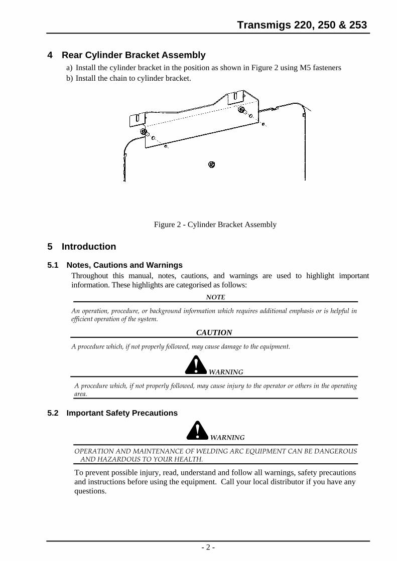
4 Rear Cylinder Bracket Assembly a) Install the cylinder bracket in the position as shown in Figure 2 using M5 fasteners b) Install the chain to cylinder bracket.
Figure 2 - Cylinder Bracket Assembly
5 Introduction
5.1 Notes, Cautions and Warnings Throughout this manual, notes, cautions, and warnings are used to highlight important information. These highlights are categorised as follows:
NOTE
An operation, procedure, or background information which requires additional emphasis or is helpful in efficient operation of the system.
CAUTION
A procedure which, if not properly followed, may cause damage to the equipment.
WARNING
A procedure which, if not properly followed, may cause injury to the operator or others in the operating area.
5.2 Important Safety Precautions
WARNING
OPERATION AND MAINTENANCE OF WELDING ARC EQUIPMENT CAN BE DANGEROUS AND HAZARDOUS TO YOUR HEALTH.
To prevent possible injury, read, understand and follow all warnings, safety precautions and instructions before using the equipment. Call your local distributor if you have any questions.
- 2 -
Transmigs 220, 250 & 253
GASES AND FUMES Gases and fumes produced during the welding process can be dangerous and hazardous to your health.
• Keep all fumes and gases from the breathing area. Keep your head out of the welding fume plume.
• Use an air-supplied respirator if ventilation is not adequate to remove all fumes and gases.
• The kinds of fumes and gases from the welding arc depend on the kind of metal being used, coatings on the metal, and the different processes. You must be very careful when cutting or welding any metals which may contain one or more of the following:
Antimony Beryllium Cobalt Manganese Selenium Arsenic Cadmium Copper Mercury Silver Barium Chromium Lead Nickel Vanadium
• Always read the Material Safety Data Sheets (MSD’s) that should be supplied with the material you are using. These MSDS’s will give you the information regarding the kind and amount of fumes and gases that may be dangerous to your health.
• For information on how to test for fumes and gases in your workplace, refer to item 1 in Subsection 5.3, Publications in this manual.
• Use special equipment, such as water or down draft cutting tables, to capture fumes and gases. • Do not use the welding torch in an area where combustible or explosive gases or materials are
located. • Phosgene, a toxic gas, is generated from the vapours of chlorinated solvents and cleansers.
Remove all sources of these vapours. • Refer to the Victorian Occupational Health and safety (Confined Spaces) Regulations 1996
and Code of Practice or its equivalent for other states and / or countries.
ELECTRIC SHOCK Electric Shock can injure or kill. The welding arc process uses and produces high voltage electrical energy. This electric energy can cause severe or fatal shock to the operator or others in the workplace. • Never touch any parts that are electrically “live” or “hot.” • Wear dry gloves and clothing. Insulate yourself from the work-piece or other parts of the
welding circuit. • Repair or replace all worn or damaged parts. • Extra care must be taken when the workplace is moist or damp. • Install and maintain equipment according to NEC code, refer to item 4 in Subsection 5.3,
Publications. • Disconnect power supply before performing any service or repairs.
Read and follow all the instructions in the Operating Manual.
- 3 -

Transmigs 220, 250 & 253
FIRE AND EXPLOSION Fire and explosion can be caused by hot slag, sparks, or the welding arc.
• Be sure there is no combustible or flammable material in the workplace. Any material that cannot be removed must be protected.
• Ventilate all flammable or explosive vapours from the workplace. • Do not cut or weld on containers that may have held combustibles. • Provide a fire watch when working in an area where fire hazards may exist. • Hydrogen gas may be formed and trapped under aluminium work-pieces when they are cut
underwater or while using a water table. DO NOT cut aluminium alloys underwater or on a water table unless the hydrogen gas can be eliminated or dissipated. Trapped hydrogen gas that is ignited will cause an explosion.
NOISE Noise can cause permanent hearing loss. Plasma arc processes can cause noise levels to exceed safe limits. You must protect your ears from loud noise to prevent permanent loss of hearing.
• To protect your hearing from loud noise, wear protective earplugs and/or earmuffs. Protect others in the workplace.
• Noise levels should be measured to be sure the decibels (sound) do not exceed safe levels. • For information on how to test for noise, see item 1 in Subsection 5.3, Publications, in this
manual.
ARC RAYS Arc Rays can injure your eyes and burn your skin. The welding arc process produces very bright ultra violet and infra red light. These arc rays will damage your eyes and burn your skin if you are not properly protected.
• To protect your eyes, always wear a welding helmet or shield. Also always wear safety glasses with side shields, goggles or other protective eye wear.
• Wear welding gloves and suitable clothing to protect your skin from the arc rays and sparks. Keep helmet and safety glasses in good condition. Replace lenses when cracked, chipped or dirty.
• Protect others in the work area from the arc rays. Use protective booths, screens or shields. • Use the shade of lens as recommended in the Operating Manual.
- 4 -
Transmigs 220, 250 & 253
5.3 Publications Refer to the following standards or their latest revisions for more information: 1. OSHA, SAFETY AND HEALTH STANDARDS, 29CFR 1910, obtainable from the
Superintendent of Documents, U.S. Government Printing Office, Washington, D.C. 20402 2. ANSI Standard Z49.1, SAFETY IN WELDING AND CUTTING, obtainable from the American
Welding Society, 550 N.W. LeJeune Rd, Miami, FL 33126 3. NIOSH, SAFETY AND HEALTH IN ARC WELDING AND GAS WELDING AND
CUTTING, obtainable from the Superintendent of Documents, U.S. Government Printing Office, Washington, D.C. 20402
4. ANSI Standard Z87.1, SAFE PRACTICES FOR OCCUPATION AND EDUCATIONAL EYE AND FACE PROTECTION, obtainable from American National Standards Institute, 1430 Broadway, New York, NY 10018
5. ANSI Standard Z41.1, STANDARD FOR MEN’S SAFETY-TOE FOOTWEAR, obtainable from the American National Standards Institute, 1430 Broadway, New York, NY 10018
6. ANSI Standard Z49.2, FIRE PREVENTION IN THE USE OF CUTTING AND WELDING PROCESSES, obtainable from American National Standards Institute, 1430 Broadway, New York, NY 10018
7. AWS Standard A6.0, WELDING AND CUTTING CONTAINERS WHICH HAVE HELD COMBUSTIBLES, obtainable from American Welding Society, 550 N.W. LeJeune Rd, Miami, FL 33126
8. NFPA Standard 51, OXYGEN-FUEL GAS SYSTEMS FOR WELDING, CUTTING AND ALLIED PROCESSES, obtainable from the National Fire Protection Association, Batterymarch Park, Quincy, MA 02269
9. NFPA Standard 70, NATIONAL ELECTRICAL CODE, obtainable from the National Fire Protection Association, Batterymarch Park, Quincy, MA 02269
10. NFPA Standard 51B, CUTTING AND WELDING PROCESSES, obtainable from the National Fire Protection Association, Batterymarch Park, Quincy, MA 02269
11. CGA Pamphlet P-1, SAFE HANDLING OF COMPRESSED GASES IN CYLINDERS, obtainable from the Compressed Gas Association, 1235 Jefferson Davis Highway, Suite 501, Arlington, VA 22202
12. CSA Standard W117.2, CODE FOR SAFETY IN WELDING AND CUTTING, obtainable from the Canadian Standards Association, Standards Sales, 178 Rexdale Boulevard, Rexdale, Ontario, Canada M9W 1R3
13. NWSA booklet, WELDING SAFETY BIBLIOGRAPHY obtainable from the National Welding Supply Association, 1900 Arch Street, Philadelphia, PA 19103
14. American Welding Society Standard AWSF4.1, RECOMMENDED SAFE PRACTICES FOR THE PREPARATION FOR WELDING AND CUTTING OF CONTAINERS AND PIPING THAT HAVE HELD HAZARDOUS SUBSTANCES, obtainable from the American Welding Society, 550 N.W. LeJeune Rd, Miami, FL 33126
15. ANSI Standard Z88.2, PRACTICE FOR RESPIRATORY PROTECTION, obtainable from American National Standards Institute, 1430 Broadway, New York, NY 10018
- 5 -
Transmigs 220, 250 & 253
6 Electromagnetic Compatibility
WARNING
Extra precautions for Electromagnetic Compatibility may be required when this welding power source is used in a domestic situation.
6.1 Installation and use – User’s Responsibility The user is responsible for installing and using the welding equipment according to the manufacturer’s instructions. If electromagnetic disturbances are detected then it shall be the responsibility of the user of the welding equipment to resolve the situation with the technical assistance of the manufacturer. In some cases this remedial action may be as simple as earthing the welding circuit. In other cases it could involve constructing an electromagnetic screen enclosing the welding power source and the work, complete with associated input filters. In all cases, electromagnetic disturbances shall be reduced to the point where they are no longer troublesome.
NOTE 1
The welding circuit may or may not be earthed for safety reasons. Changing the earthing arrangements should only be authorised by a person who is competent to assess whether the changes will increase the risk of injury, e.g. by allowing parallel welding current return paths which may damage the earth circuits of other equipment. Further guidance is given in IEC 974-13 Arc Welding Equipment - Installation and use (under preparation).
6.2 Assessment of Area Before installing welding equipment, the user shall make an assessment of potential electromagnetic problems in the surrounding area. The following shall be taken into account
i) Other supply cables, control cables, signalling and telephone cables; above, below and adjacent to the welding equipment.
ii) Radio, television transmitters and receivers. iii) Computer and other control equipment. iv) Safety critical equipment, e.g. guarding of industrial equipment. v) The health of people around, e.g. the use of pacemakers and hearing aids. vi) Equipment used for calibration and measurement. vii) The immunity of other equipment in the environment, the user shall ensure that other
equipment being used in the environment is compatible. This may require additional protection measures.
viii) The time of day that welding or other activities are to be carried out. The size of the surrounding area to be considered will depend on the structure of the building and other activities that are taking place. The surrounding area may extend beyond the boundaries of the premises.
- 6 -

Transmigs 220, 250 & 253
7 Electromagnetic Compatibility - Methods Of Reducing Emissions
7.1 Mains Supply Welding equipment should be connected to the mains supply according to the manufacturer’s recommendations. If interference occurs, it may be necessary to take additional precautions such as filtering of the mains supply. Consideration should be given to shielding the supply cable of permanently installed welding equipment in metallic conduit or equivalent. Shielding should be electrically continuous throughout its length. The shielding should be connected to the welding power source so that good electrical contact is maintained between the conduit and the welding power source enclosure.
7.2 Maintenance of Welding Equipment The welding equipment should be routinely maintained according to the manufacturer’s recommendations. All access and service doors and covers should be closed and properly fastened when the welding equipment is in operation. The welding equipment should not be modified in any way except for those changes and adjustments covered in the manufacturer’s instructions. In particular, the spark gaps of arc striking and stabilising devices should be adjusted and maintained according to the manufacturer’s recommendations.
7.3 Welding Cables The welding cables should be kept as short as possible and should be positioned close together, running at or close to the floor level.
7.4 Equipotential Bonding Bonding of all metallic components in the welding installation and adjacent to it should be considered. However, Metallic components bonded to the work piece will increase the risk that the operator could receive a shock by touching the metallic components and the electrode at the same time. The operator should be insulated from all such bonded metallic components.
7.5 Earthing of the Work-piece Where the work-piece is not bonded to earth for electrical safety, nor connected to earth because of it’s size and position, e.g. ship’s hull or building steelwork, a connection bonding the work-piece to earth may reduce emissions in some, but not all instances. Care should be taken to prevent the earthing of the work-piece increasing the risk of injury to users, or damage to other electrical equipment. Where necessary, the connection of the work-piece to earth should be made by direct connection to the work-piece, but in some countries where direct connection is not permitted, the bonding should be achieved by suitable capacitance, selected according to national regulations.
7.6 Screening and Shielding Selective screening and shielding of other cables and equipment in the surrounding area may alleviate problems of interference. Screening the entire welding installation may be considered for special applications.
- 7 -
Transmigs 220, 250 & 253
8 General Information These TRANSMIG’s are semi-automatic Gas Metal Arc Welders (GMAW-commonly MIG). They are designed is to meet the broad operating needs of the metal fabrication industry where production efficiency is vital. Australian Standard AS1966.1 was used to guide the design.
The TRANSMIG range gives excellent performance on mild steel, stainless steel, aluminium, silicon bronze and some hard facing wires with Argon based shielding gases. The Power Sources also give excellent results on mild steel using Carbon Dioxide shielding gas.
The TRANSMIG range is supplied as a complete package ready to weld (apart from shielding gas, electrode wire and Hiderok TM welding helmet). The following instructions detail how to correctly set up the machine and give guidelines on gaining the best production efficiency from the Power Source. Please read these instructions thoroughly before using your TRANSMIG welder.
8.1 User Responsibility This equipment will perform as per the information contained herein when installed, operated, maintained and repaired in accordance with the instructions provided. This equipment must be checked periodically. Defective equipment (including welding leads) should not be used. Parts that are broken, missing, plainly worn, distorted or contaminated, should be replaced immediately. Should such repairs or replacements become necessary, it is recommended that such repairs be carried out by appropriately qualified persons approved by CIGWELD. Advice in this regard can be obtained by contacting CIGWELD. This equipment or any of its parts should not be altered from standard specification without prior written approval of CIGWELD. The user of this equipment shall have the sole responsibility for any malfunction which results from improper use or unauthorised modification from standard specification, faulty maintenance, damage or improper repair by anyone other than appropriately qualified persons approved by CIGWELD.
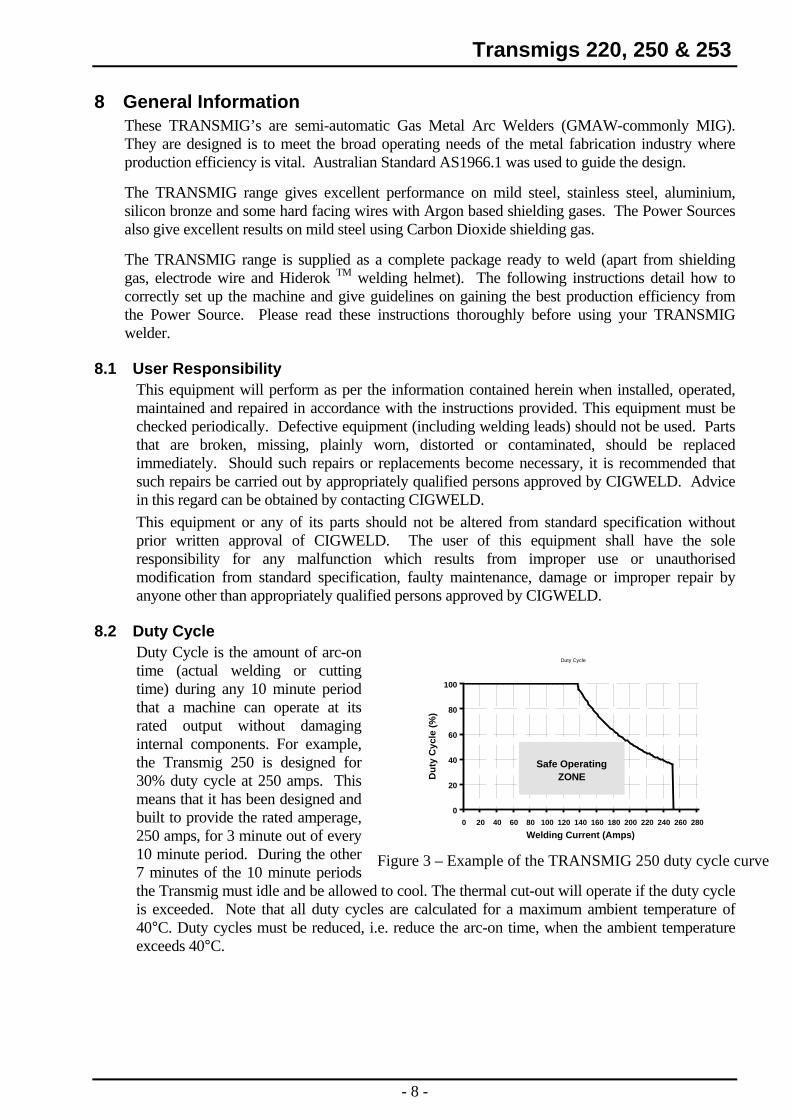
8.2 Duty Cycle Duty Cycle is the amount of arc-on time (actual welding or cutting time) during any 10 minute period that a machine can operate at its rated output without damaging internal components. For example, the Transmig 250 is designed for 30% duty cycle at 250 amps. This means that it has been designed and built to provide the rated amperage, 250 amps, for 3 minute out of every 10 minute period. During the other 7 minutes of the 10 minute periods the Transmig must idle and be allowed to cool. The thermal cut-out will operate if the duty cycle is exceeded. Note that all duty cycles are calculated for a maximum ambient temperature of 40°C. Duty cycles must be reduced, i.e. reduce the arc-on time, when the ambient temperature exceeds 40°C.
Duty Cycle
0
20
40
60
80
100
0 20 40 60 80 100 120 140 160 180 200 220 240 260 280
Welding Current (Amps)
Dut
y C
ycle
(%)
Safe OperatingZONE
Figure 3 – Example of the TRANSMIG 250 duty cycle curve
- 8 -
Transmigs 220, 250 & 253
8.3 Terms Of Warranty - May 2001 1. The Trade Practices Act 1974 (Australian Commonwealth) and similar State Territory legislation relating to
the supply of goods and services, protects consumers' interests by ensuring that consumers are entitled in certain situations to the benefit of various conditions, warranties, guarantees, rights and remedies (including warranties as to merchantability and fitness for purpose) associated with the supply of goods and services. A consumer should seek legal advice as to the nature and extent of these protected interests. In some circumstances, the supplier of goods and services may legally stipulate that the said conditions, warranties, guarantees, rights and remedies are limited or entirely excluded. The warranties set out in Clause 2 shall be additional to any non-excludable warranties to which the Customer may be entitled pursuant to any statute.
2. Subject to Clause 3. CIGWELD gives the following warranties to the Customer:
Insofar as they are manufactured or imported by CIGWELD, goods will upon delivery be of merchantable quality and reasonably fit for the purpose for which they are supplied by CIGWELD.
CIGWELD will repair or, at its option, replace those of the goods which, upon examination, are found by CIGWELD to be defective in workmanship and/or materials.
CIGWELD reserves the right to request documented evidence of date of purchase.
3. The Warranty in Clause 2;
Is conditional upon:
The Customer notifying CIGWELD or our Accredited Distributor in writing of its claim within seven (7) days of becoming aware of the basis thereof, and at its own expense returning the goods which are the subject of the claim to CIGWELD or nominated Accredited Distributor/Accredited Service Agent.
The goods being used in accordance with the Manufacturer's Operating Manuals, and under competent supervision.
Does not apply to:
Obsolete goods sold at auction, second-hand goods and prototype goods.
Breakdown or malfunction caused by accident, misuse or normal wear and tear.
Repairs or replacement made other than by CIGWELD or Accredited Service Agents, unless by prior arrangement with CIGWELD.
Replacement parts or accessories which may affect product safety or performance and which are not manufactured, distributed or approved by CIGWELD.
4. CIGWELD declares that, to the extent permitted by law, it hereby limits its liability in respect of the supply of goods which are not of a kind ordinarily acquired for personal, domestic or household use or consumption to any one or more of the following (the choice of which shall be at the option of CIGWELD).
The replacement of the goods or the supply of equivalent goods.
The repair of goods.
The payment of cost of replacing the goods or acquiring equivalent goods.
The payment of the cost of having goods repaired.
5. Except as provided in Clauses 2 to 4 above, to the extent permitted by statute, CIGWELD hereby excludes all liability for any loss, damage, death or injury of any kind whatsoever occasioned to the Customer in respect of the supply of goods including direct, indirect, consequential or incidental loss, damage or injury of any kind.
- 9 -
Transmigs 220, 250 & 253
8.4 Transmig Warranty Schedule - May 2001 These warranty periods relate to the warranty conditions in clause 2. All warranty periods are from date of sale from the Accredited Distributor of the equipment. Notwithstanding the foregoing, in no event shall the warranty period extend more than the time stated plus one year from the date CIGWELD delivered the product to the Accredited Distributor. Unless otherwise stated the warranty period includes parts and labour. CIGWELD reserves the right to request documented evidence of date of purchase.
WARRANTY PERIODGMAW EQUIPMENTTransmig
Main Welding Transformer and Inductor (Power Magnetics)................................................. .3 years Original Main Power Rectifiers, Control P.C. Boards...............................................................1 year All other circuits and components including, but not limited to, relays, switches, contactors, solenoids, fans, power switch semi-conductors .......................................1 year MIG Torch ............................................................................................................................….3 months
Please note that the information detailed in this statement supersedes any prior published data produced by CIGWELD.
9 Safe Practices For The Use Of Welding Equipment In many situations the “striking” voltage can be hazardous. Any person touching simultaneously the electrode lead/terminal and the work lead/terminal may receive a serious electrical shock. Additional precautions must be exercised where two Welding Power Sources are being used close to each other because, under certain conditions, the voltages between the welding terminals of the two Welding Power Sources could be two times the specified open circuit voltage.
It is essential that the Welding Power Source be correctly installed, if necessary, by a qualified electrician and maintained in sound mechanical and electrical condition. It is also important that the Welding Power Source be switched off when not in use.
9.1 Precautions to be taken by Operators ♦ Whenever practicable, all parts of the welding circuit should be isolated from earth and other
conducting material and under no circumstances should any earthing conductor of the electrical installation be used in place of the work lead.
♦ The Mains supply voltage should be switched off before connecting or disconnecting welding leads. Welding lead connections must have clean contact surfaces and must be securely tightened. Poor connections will result in overheating and loss of welding current. All parts of the welding circuit, including the return paths, are to be considered electrically alive, so the operator must ensure that no part of the body is placed in such a position that it will provide a path for an electric current.
♦ Welding operators should avoid direct contact with the work to be welded or against any metal in contact with the work. When this cannot be avoided the operator must not touch any exposed portion of the MIG Torch with any part of the body. Should this occur, the operator will risk completing the electrical circuit through the body.
♦ When welding in confined spaces where reasonable movement is restricted ensure that the area is well ventilated and the operator is under constant observation by a person who can immediately switch off power and give assistance in an emergency.
♦ During pauses between welding runs, MIG Torch should be so placed that they cannot make electrical contact with persons or conductive objects.
♦ The welding leads, both the MIG Torch lead and the work lead must be protected from damage. Damaged leads must not be used.
♦ Keep combustible materials from welding area. Have a suitable fire extinguisher handy. ♦ Do not stand on damp ground when welding.
- 10 -
Transmigs 220, 250 & 253 9.2 Personal Protection
The radiation from an electric arc during the welding process can seriously harm eyes and skin. It is essential that the following precautions be taken: ♦ Gloves should be flameproof gauntlet type to protect hands and wrists from heat burns and
harmful radiations. They should be kept dry and in good repair. ♦ Protective clothing must protect the operator from burns, spatter and harmful radiation.
Woollen clothing is preferable to cotton because of its greater flame resistance. Clothing should be free from oil or grease. Wear leggings and spats to protect the lower portion of the legs and to prevent slag and molten metal from falling into boots or shoes.
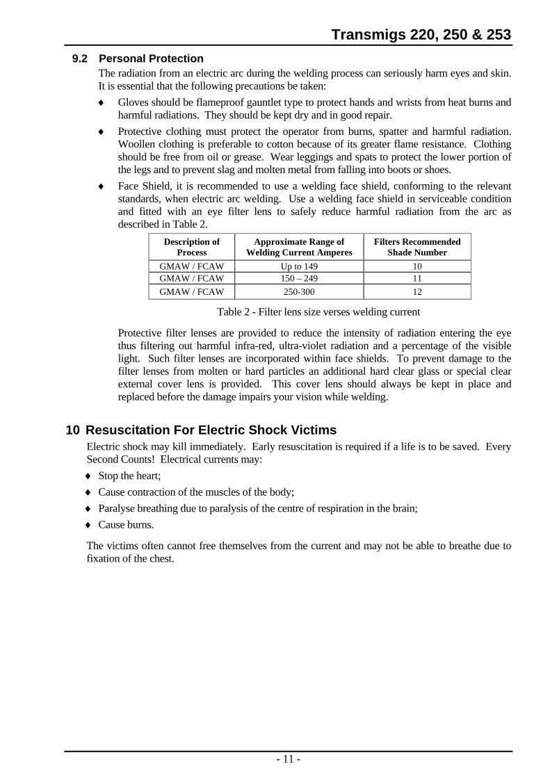
♦ Face Shield, it is recommended to use a welding face shield, conforming to the relevant standards, when electric arc welding. Use a welding face shield in serviceable condition and fitted with an eye filter lens to safely reduce harmful radiation from the arc as described in Table 2.
Description of Process
Approximate Range of Welding Current Amperes
Filters Recommended Shade Number
GMAW / FCAW Up to 149 10 GMAW / FCAW 150 – 249 11 GMAW / FCAW 250-300 12
Table 2 - Filter lens size verses welding current
Protective filter lenses are provided to reduce the intensity of radiation entering the eye thus filtering out harmful infra-red, ultra-violet radiation and a percentage of the visible light. Such filter lenses are incorporated within face shields. To prevent damage to the filter lenses from molten or hard particles an additional hard clear glass or special clear external cover lens is provided. This cover lens should always be kept in place and replaced before the damage impairs your vision while welding.
10 Resuscitation For Electric Shock Victims Electric shock may kill immediately. Early resuscitation is required if a life is to be saved. Every Second Counts! Electrical currents may: ♦ Stop the heart; ♦ Cause contraction of the muscles of the body; ♦ Paralyse breathing due to paralysis of the centre of respiration in the brain; ♦ Cause burns.
The victims often cannot free themselves from the current and may not be able to breathe due to fixation of the chest.
- 11 -
Transmigs 220, 250 & 253 10.1 Resuscitation
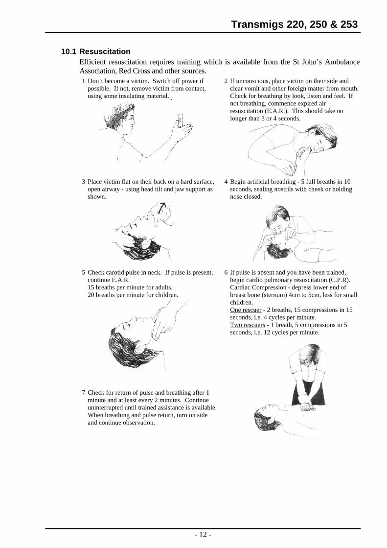
Efficient resuscitation requires training which is available from the St John’s Ambulance Association, Red Cross and other sources.
2 If unconscious, place victim on their side and clear vomit and other foreign matter from mouth. Check for breathing by look, listen and feel. If not breathing, commence expired air resuscitation (E.A.R.). This should take no longer than 3 or 4 seconds.
1 Don’t become a victim. Switch off power if possible. If not, remove victim from contact, using some insulating material.
4 Begin artificial breathing - 5 full breaths in 10 seconds, sealing nostrils with cheek or holding nose closed.
3 Place victim flat on their back on a hard surface, open airway - using head tilt and jaw support as shown.
6 If pulse is absent and you have been trained, begin cardio pulmonary resuscitation (C.P.R). Cardiac Compression - depress lower end of breast bone (sternum) 4cm to 5cm, less for small children.
5 Check carotid pulse in neck. If pulse is present, continue E.A.R. 15 breaths per minute for adults. 20 breaths per minute for children.
One rescuer - 2 breaths, 15 compressions in 15 seconds, i.e. 4 cycles per minute. Two rescuers - 1 breath, 5 compressions in 5 seconds, i.e. 12 cycles per minute.
7 Check for return of pulse and breathing after 1
minute and at least every 2 minutes. Continue uninterrupted until trained assistance is available. When breathing and pulse return, turn on side and continue observation.
- 12 -
Transmigs 220, 250 & 253
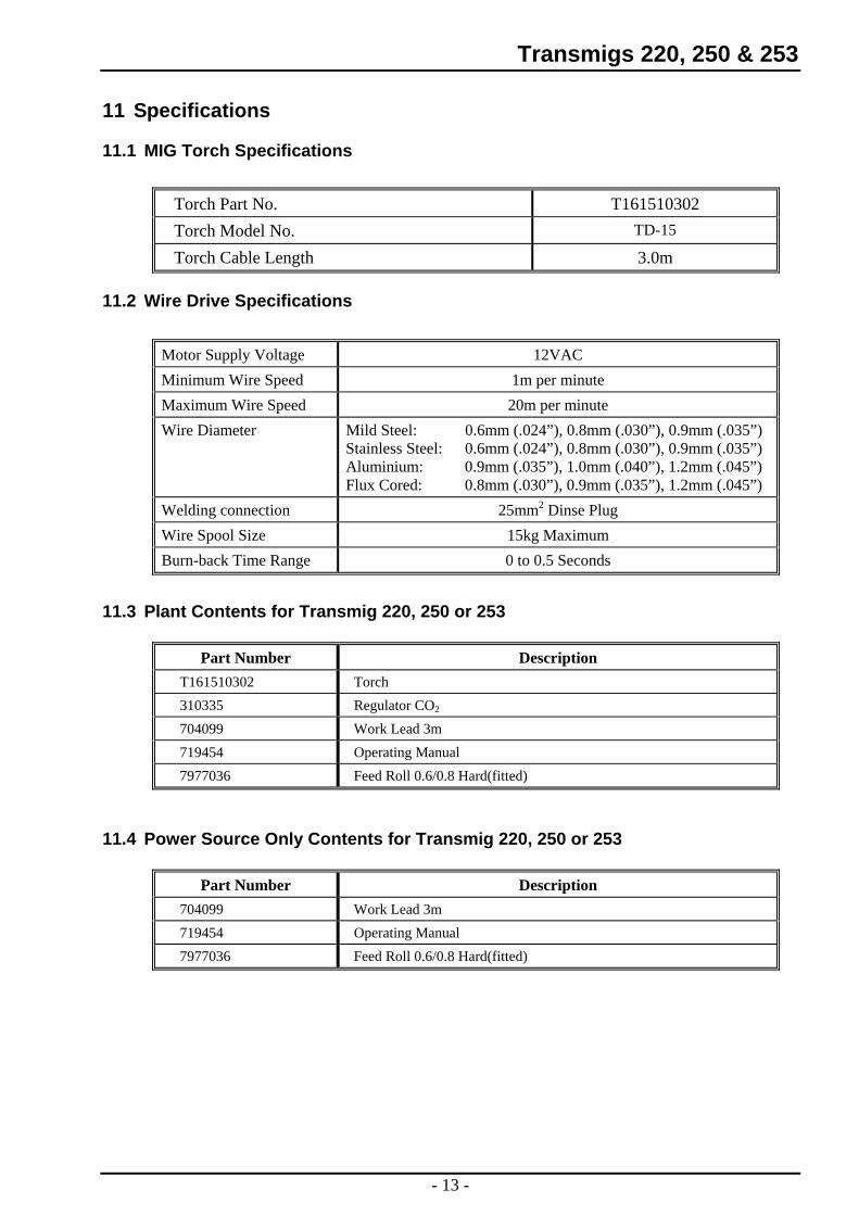
11 Specifications
11.1 MIG Torch Specifications
Torch Part No. T161510302 TD-15 Torch Model No.
Torch Cable Length 3.0m
11.2 Wire Drive Specifications
Motor Supply Voltage 12VAC Minimum Wire Speed 1m per minute Maximum Wire Speed 20m per minute Wire Diameter Mild Steel: 0.6mm (.024”), 0.8mm (.030”), 0.9mm (.035”)
Stainless Steel: 0.6mm (.024”), 0.8mm (.030”), 0.9mm (.035”) Aluminium: 0.9mm (.035”), 1.0mm (.040”), 1.2mm (.045”) Flux Cored: 0.8mm (.030”), 0.9mm (.035”), 1.2mm (.045”)
Welding connection 25mm2 Dinse Plug Wire Spool Size 15kg Maximum Burn-back Time Range 0 to 0.5 Seconds
11.3 Plant Contents for Transmig 220, 250 or 253
Part Number Description T161510302 Torch 310335 Regulator CO2
704099 Work Lead 3m 719454 Operating Manual 7977036 Feed Roll 0.6/0.8 Hard(fitted)
11.4 Power Source Only Contents for Transmig 220, 250 or 253
Part Number Description 704099 Work Lead 3m 719454 Operating Manual 7977036 Feed Roll 0.6/0.8 Hard(fitted)
- 13 -
Transmigs 220, 250 & 253 11.5 Machine Specifications
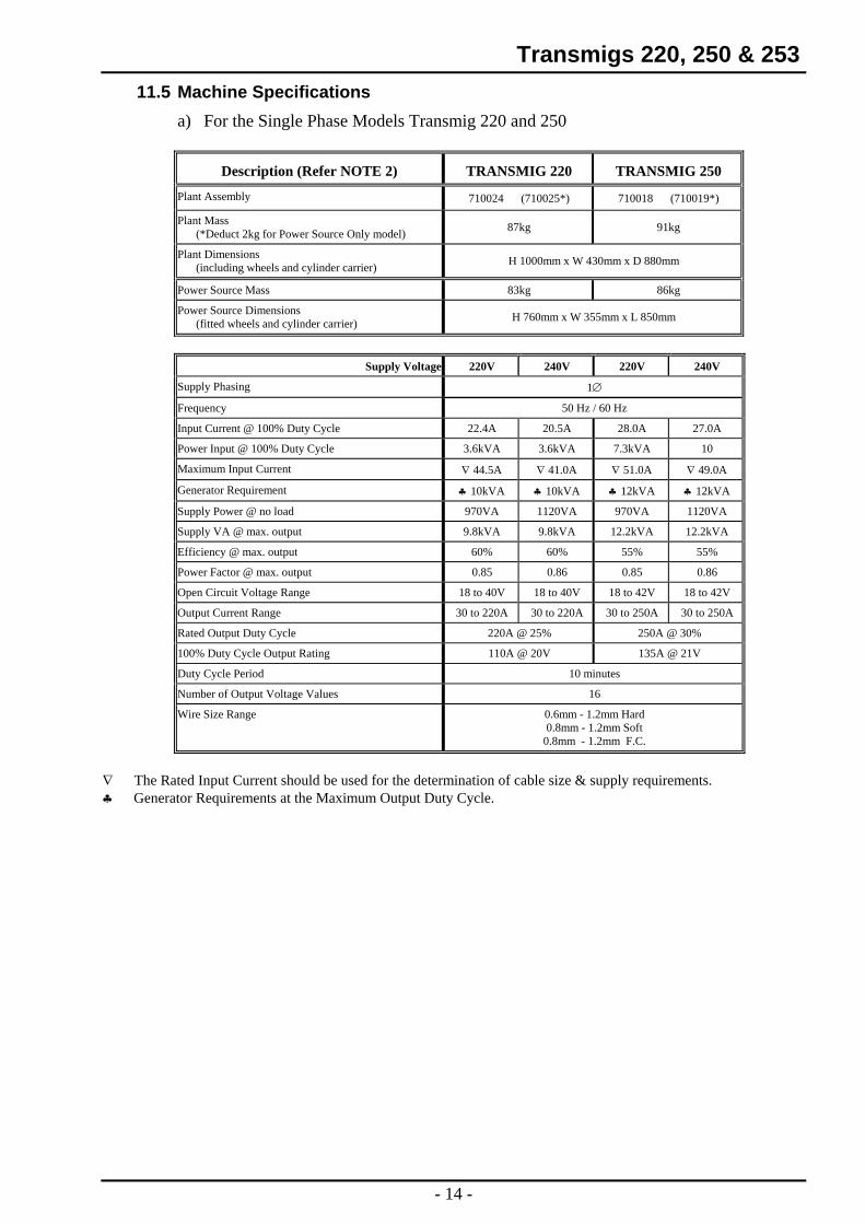
a) For the Single Phase Models Transmig 220 and 250
Description (Refer NOTE 2) TRANSMIG 220 TRANSMIG 250
Plant Assembly 710024 (710025*) 710018 (710019*)
Plant Mass (*Deduct 2kg for Power Source Only model) 87kg 91kg
Plant Dimensions (including wheels and cylinder carrier) H 1000mm x W 430mm x D 880mm
Power Source Mass 83kg 86kg
Power Source Dimensions (fitted wheels and cylinder carrier) H 760mm x W 355mm x L 850mm
Supply Voltage 220V 240V 220V 240V
Supply Phasing 1∅
Frequency 50 Hz / 60 Hz
Input Current @ 100% Duty Cycle 22.4A 20.5A 28.0A 27.0A
Power Input @ 100% Duty Cycle 3.6kVA 3.6kVA 7.3kVA 10
Maximum Input Current ∇ 44.5A ∇ 41.0A ∇ 51.0A ∇ 49.0A
Generator Requirement ♣ 10kVA ♣ 10kVA ♣ 12kVA ♣ 12kVA
Supply Power @ no load 970VA 1120VA 970VA 1120VA
Supply VA @ max. output 9.8kVA 9.8kVA 12.2kVA 12.2kVA
Efficiency @ max. output 60% 60% 55% 55%
Power Factor @ max. output 0.85 0.86 0.85 0.86
Open Circuit Voltage Range 18 to 40V 18 to 40V 18 to 42V 18 to 42V
Output Current Range 30 to 220A 30 to 220A 30 to 250A 30 to 250A
Rated Output Duty Cycle 220A @ 25% 250A @ 30%
100% Duty Cycle Output Rating 110A @ 20V 135A @ 21V
Duty Cycle Period 10 minutes
Number of Output Voltage Values 16
Wire Size Range 0.6mm - 1.2mm Hard 0.8mm - 1.2mm Soft
0.8mm - 1.2mm F.C.
∇ The Rated Input Current should be used for the determination of cable size & supply requirements. ♣ Generator Requirements at the Maximum Output Duty Cycle.
- 14 -
Transmigs 220, 250 & 253
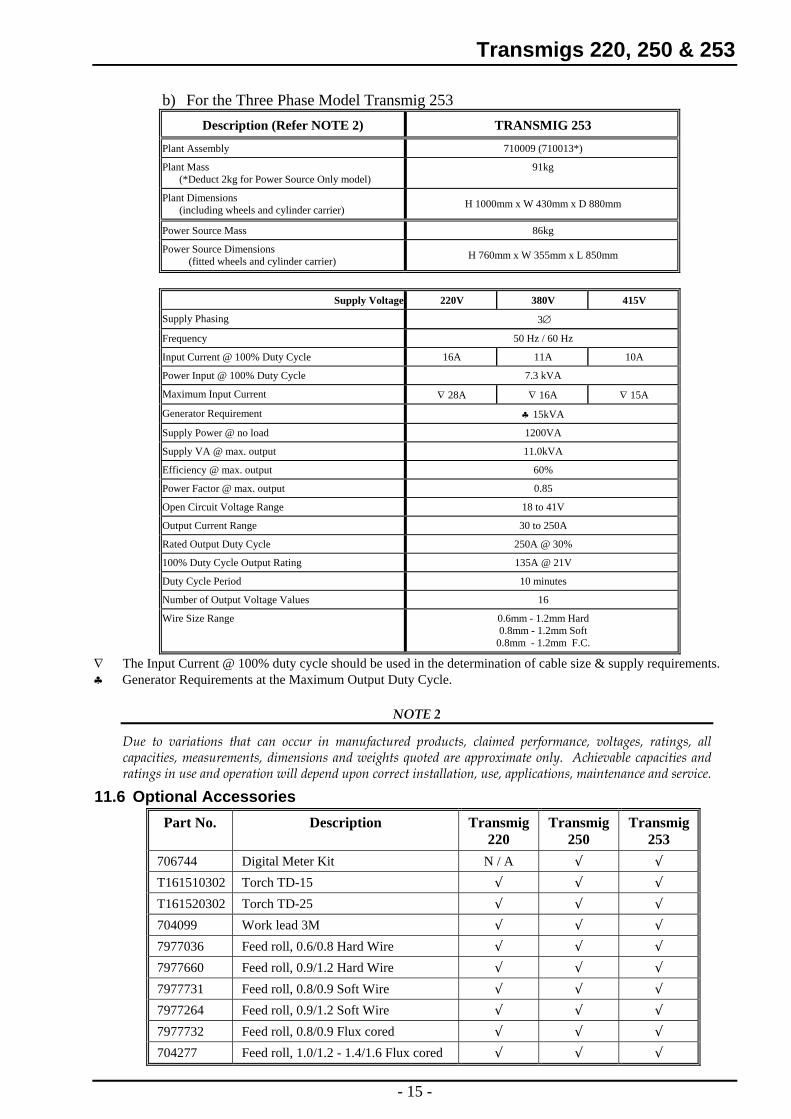
b) For the Three Phase Model Transmig 253 Description (Refer NOTE 2) TRANSMIG 253
Plant Assembly 710009 (710013*)
Plant Mass (*Deduct 2kg for Power Source Only model)
91kg
Plant Dimensions (including wheels and cylinder carrier) H 1000mm x W 430mm x D 880mm
Power Source Mass 86kg
Power Source Dimensions (fitted wheels and cylinder carrier) H 760mm x W 355mm x L 850mm
Supply Voltage 220V 380V 415V
Supply Phasing 3∅
Frequency 50 Hz / 60 Hz
Input Current @ 100% Duty Cycle 16A 11A 10A
Power Input @ 100% Duty Cycle 7.3 kVA
Maximum Input Current ∇ 28A ∇ 16A ∇ 15A
Generator Requirement ♣ 15kVA
Supply Power @ no load 1200VA
Supply VA @ max. output 11.0kVA
Efficiency @ max. output 60%
Power Factor @ max. output 0.85
Open Circuit Voltage Range 18 to 41V
Output Current Range 30 to 250A
Rated Output Duty Cycle 250A @ 30%
100% Duty Cycle Output Rating 135A @ 21V
Duty Cycle Period 10 minutes
Number of Output Voltage Values 16
Wire Size Range 0.6mm - 1.2mm Hard 0.8mm - 1.2mm Soft
0.8mm - 1.2mm F.C.
∇ The Input Current @ 100% duty cycle should be used in the determination of cable size & supply requirements. ♣ Generator Requirements at the Maximum Output Duty Cycle.
NOTE 2
Due to variations that can occur in manufactured products, claimed performance, voltages, ratings, all capacities, measurements, dimensions and weights quoted are approximate only. Achievable capacities and ratings in use and operation will depend upon correct installation, use, applications, maintenance and service.
11.6 Optional Accessories Part No. Description Transmig
220 Transmig
250 Transmig
253 706744 Digital Meter Kit N / A √ √ T161510302 Torch TD-15 √ √ √ T161520302 Torch TD-25 √ √ √ 704099 Work lead 3M √ √ √ 7977036 Feed roll, 0.6/0.8 Hard Wire √ √ √ 7977660 Feed roll, 0.9/1.2 Hard Wire √ √ √ 7977731 Feed roll, 0.8/0.9 Soft Wire √ √ √ 7977264 Feed roll, 0.9/1.2 Soft Wire √ √ √ 7977732 Feed roll, 0.8/0.9 Flux cored √ √ √ 704277 Feed roll, 1.0/1.2 - 1.4/1.6 Flux cored √ √ √
- 15 -
Transmigs 220, 250 & 253 12 Installation Recommendations
12.1 Environment The TRANSMIG’s are NOT designed for use in environments with increased hazard of electric shock..
a) Examples of environments with increased hazard of electric shock are:- i) In locations where freedom of movement is restricted and operator is forced to
perform the work in a cramped (kneeling, sitting or lying) position in physical contact with conductive parts.
ii) In locations which are fully or partially limited by conductive elements, and in which there is a high risk of unavoidable or accidental contact by the operator.
iii) In wet or damp hot locations where humidity or perspiration considerable reduces the skin resistance of the human body and the insulation properties of accessories.
b) Environments with increased hazard of electric shock do not include places where electrically conductive parts in the near vicinity of the operator, which can cause increased hazard, have been insulated.
12.2 Location Be sure to locate the Power Source according to the following guidelines:-
a) In areas, free from moisture and dust. b) In areas, free from oil, steam and corrosive gases. c) In areas, not subjected to abnormal vibration or shock. d) In areas, not exposed to direct sunlight or rain. e) In areas, with an ambient temperature of between -10 °C and 40 °C. f) Position 30cm or more from walls that could restrict cooling by natural airflow. g) The minimum ground clearance for these products is 80mm.
12.3 Ventilation Since the inhalation of welding fumes can be harmful, ensure that the welding area is effectively ventilated.
12.4 Mains Supply Voltage Requirements The Mains supply voltage should be within ± 10% of the rated Mains supply voltage. Too low a voltage may cause poor welding performance or the wirefeeder malfunction. Too high a supply voltage will cause components to overheat and possibly fail.
12.5 Mains Current Circuit Requirements For Maximum Weld Current The Welding Power Source must be:
♦ Correctly installed, if necessary, by a qualified electrician. ♦ Correctly earthed (electrically) in accordance with local regulations. ♦ Connected to the correct size Mains Current Circuit as per the Table 3.
- 16 -
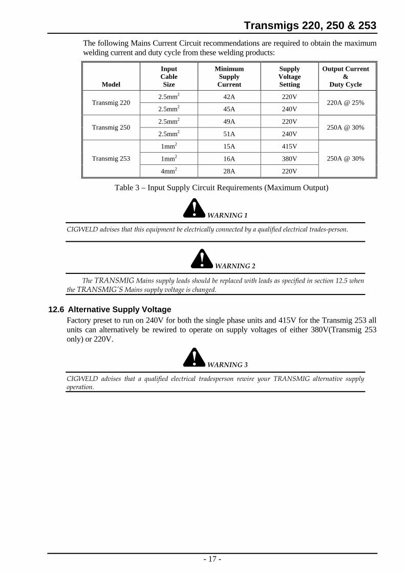
Transmigs 220, 250 & 253 The following Mains Current Circuit recommendations are required to obtain the maximum welding current and duty cycle from these welding products:
Model
Input Cable Size
Minimum Supply Current
Supply Voltage Setting
Output Current &
Duty Cycle
2.5mm2 42A 220V Transmig 220
2.5mm2 45A 240V 220A @ 25%
2.5mm2 49A 220V Transmig 250
2.5mm2 51A 240V 250A @ 30%
1mm2 15A 415V
1mm2 16A 380V 250A @ 30% Transmig 253
4mm2 28A 220V
Table 3 – Input Supply Circuit Requirements (Maximum Output)
WARNING 1
CIGWELD advises that this equipment be electrically connected by a qualified electrical trades-person.
WARNING 2
The TRANSMIG Mains supply leads should be replaced with leads as specified in section 12.5 when the TRANSMIG’S Mains supply voltage is changed.
12.6 Alternative Supply Voltage Factory preset to run on 240V for both the single phase units and 415V for the Transmig 253 all units can alternatively be rewired to operate on supply voltages of either 380V(Transmig 253 only) or 220V.
WARNING 3
CIGWELD advises that a qualified electrical tradesperson rewire your TRANSMIG alternative supply operation.
- 17 -
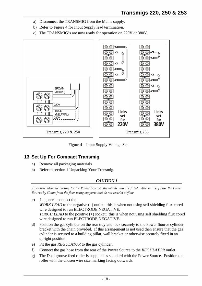
Transmigs 220, 250 & 253 a) Disconnect the TRANSMIG from the Mains supply. b) Refer to Figure 4 for Input Supply lead termination. c) The TRANSMIG’s are now ready for operation on 220V or 380V.
Linkssetfor
380V
Linkssetfor
220V
220V
240V
BLUE(NEUTRAL)
BROWN(ACTIVE)
Transmig 220 & 250 Transmig 253
Figure 4 – Input Supply Voltage Set
13 Set Up For Compact Transmig a) Remove all packaging materials. b) Refer to section 1 Unpacking Your Transmig.
CAUTION 1
To ensure adequate cooling for the Power Source the wheels must be fitted. Alternatively raise the Power Source by 80mm from the floor using supports that do not restrict airflow.
c) In general connect the WORK LEAD to the negative (−) outlet; this is when not using self shielding flux cored wire designed to run ELECTRODE NEGATIVE. TORCH LEAD to the positive (+) socket; this is when not using self shielding flux cored wire designed to run ELECTRODE NEGATIVE.
d) Position the gas cylinder on the rear tray and lock securely to the Power Source cylinder bracket with the chain provided. If this arrangement is not used then ensure that the gas cylinder is secured to a building pillar, wall bracket or otherwise securely fixed in an upright position.
e) Fit the gas REGULATOR to the gas cylinder. f) Connect the gas hose from the rear of the Power Source to the REGULATOR outlet. g) The Duel groove feed roller is supplied as standard with the Power Source. Position the
roller with the chosen wire size marking facing outwards.
- 18 -
Transmigs 220, 250 & 253 h) Fit the spool of wire to the wire hub located behind the electrode wire compartment door.
Ensure that the drive dog-pin engages the mating hole in the wire spool. Push the 'R' clip into place to retain the wire spool securely. The wire should feed from the bottom of spool.
i) Align and fit the back-end of the TORCH into the torch adaptor then lock into place by screwing the retaining ring. Remove the contact tip from the torch front-end.
j) Lift up the wire feeder pressure lever and pass the electrode wire through the inlet guide, between the rollers, through the outlet guide and into the torch.
k) Lower the pressure lever and with the torch lead reasonably straight, feed the wire through the torch. Fit the appropriate contact tip.
WARNING 4
The electrode wire will be at welding voltage potential whilst it is being fed through the system.
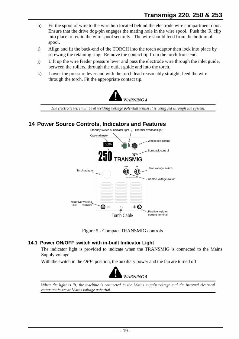
14 Power Source Controls, Indicators and Features
14
Amps/Vol ts
1
2
3
4
DO N O T SW ITC H W H IL E W ELD IN G
COARSE FINE
WIREFEEDER
14
1
3
2
4
Optional meter
Fine voltage switch
Wirefeedercontrol socket
Torch adaptor
Positive weldingcurrent terminal
Negative weldingcurrent terminal
888AO P T I O N A L K I T P / N 7 0 5 1 0 3
STANDBY
POWERON
Thermal overload lightStandby switch & indicator light
Wirespeed control
(m/min)
220
18
16
14
12108
6
4
BURNBACK
Burnback control
Torch Cable
Figure 5 - Compact TRANSMIG controls
14.1 Power ON/OFF switch with in-built Indicator Light The indicator light is provided to indicate when the TRANSMIG is connected to the Mains Supply voltage. With the switch in the OFF position, the auxiliary power and the fan are turned off.
WARNING 5
When the light is lit, the machine is connected to the Mains supply voltage and the internal electrical components are at Mains voltage potential.
- 19 -
Transmigs 220, 250 & 253 14.2 Coarse Voltage Control Switch and Fine Voltage Control Switch
The Coarse Voltage Control sets the voltage level to the welding terminals as it is rotated in the clockwise direction. The Fine Voltage Control switch increases the voltage (in smaller increments than the Coarse switch) as it is rotated in the clockwise direction.
CAUTION 2
The Coarse & Fine Voltage Control switches MUST NOT BE SWITCHED during welding.
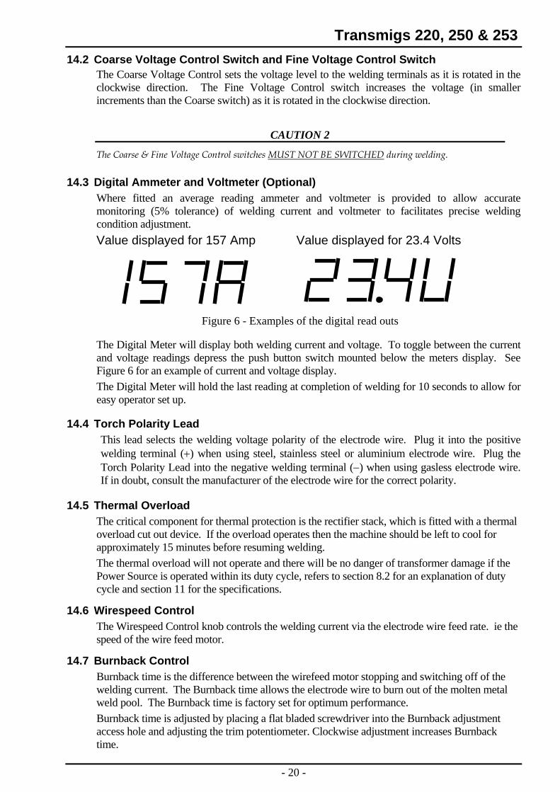
14.3 Digital Ammeter and Voltmeter (Optional) Where fitted an average reading ammeter and voltmeter is provided to allow accurate monitoring (5% tolerance) of welding current and voltmeter to facilitates precise welding condition adjustment. Value displayed for 157 Amp Value displayed for 23.4 Volts
Figure 6 - Examples of the digital read outs
The Digital Meter will display both welding current and voltage. To toggle between the current and voltage readings depress the push button switch mounted below the meters display. See Figure 6 for an example of current and voltage display. The Digital Meter will hold the last reading at completion of welding for 10 seconds to allow for easy operator set up.
14.4 Torch Polarity Lead This lead selects the welding voltage polarity of the electrode wire. Plug it into the positive welding terminal (+) when using steel, stainless steel or aluminium electrode wire. Plug the Torch Polarity Lead into the negative welding terminal (−) when using gasless electrode wire. If in doubt, consult the manufacturer of the electrode wire for the correct polarity.
14.5 Thermal Overload The critical component for thermal protection is the rectifier stack, which is fitted with a thermal overload cut out device. If the overload operates then the machine should be left to cool for approximately 15 minutes before resuming welding. The thermal overload will not operate and there will be no danger of transformer damage if the Power Source is operated within its duty cycle, refers to section 8.2 for an explanation of duty cycle and section 11 for the specifications.
14.6 Wirespeed Control The Wirespeed Control knob controls the welding current via the electrode wire feed rate. ie the speed of the wire feed motor.
14.7 Burnback Control Burnback time is the difference between the wirefeed motor stopping and switching off of the welding current. The Burnback time allows the electrode wire to burn out of the molten metal weld pool. The Burnback time is factory set for optimum performance. Burnback time is adjusted by placing a flat bladed screwdriver into the Burnback adjustment access hole and adjusting the trim potentiometer. Clockwise adjustment increases Burnback time.
- 20 -
Transmigs 220, 250 & 253 14.8 Wirefeeder Drive Roller Pressure Adjustment
The moveable roller applies pressure to the grooved roller via screw adjustable spring pressure. The adjustable spring screw should be adjusted to a minimum pressure that will provide satisfactory wire feed without slippage. If slipping occurs, and inspection of the wire contact tip reveals no wear, distortion or burn-back jam, the conduit liner should be checked for kinks and clogging by metal flakes and swarf. If this is not the cause of slipping, the feed roller pressure can be increased by rotating the adjustable spring screw clockwise. The use of excessive pressure may cause rapid wear of the feed roller, motor shaft and motor bearings.
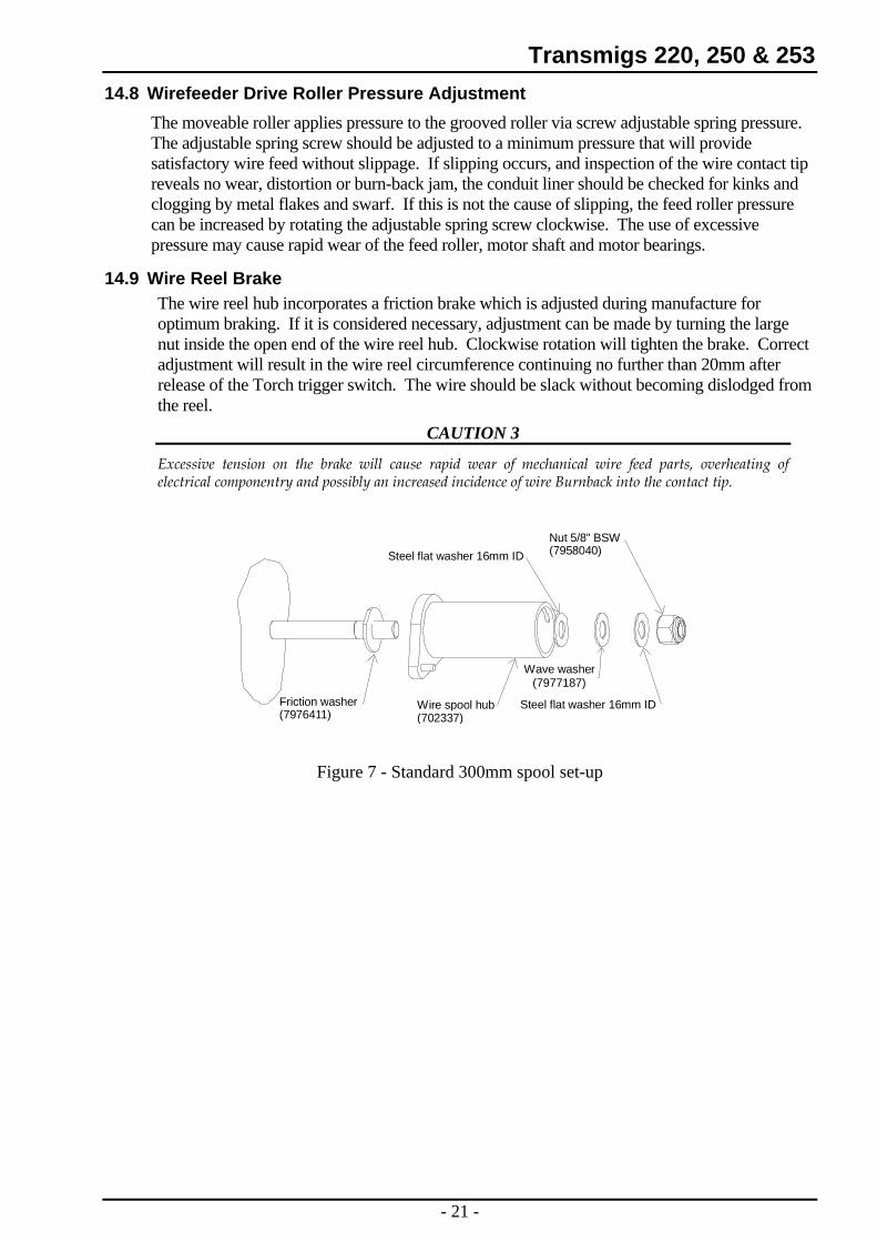
14.9 Wire Reel Brake The wire reel hub incorporates a friction brake which is adjusted during manufacture for optimum braking. If it is considered necessary, adjustment can be made by turning the large nut inside the open end of the wire reel hub. Clockwise rotation will tighten the brake. Correct adjustment will result in the wire reel circumference continuing no further than 20mm after release of the Torch trigger switch. The wire should be slack without becoming dislodged from the reel.
CAUTION 3
Excessive tension on the brake will cause rapid wear of mechanical wire feed parts, overheating of electrical componentry and possibly an increased incidence of wire Burnback into the contact tip.
Friction washer(7976411)
Wire spool hub(702337)
Nut 5/8" BSW(7958040)Steel flat washer 16mm ID
Steel flat washer 16mm ID
Wave washer(7977187)
Figure 7 - Standard 300mm spool set-up
- 21 -
Transmigs 220, 250 & 253
15 MIG Torch
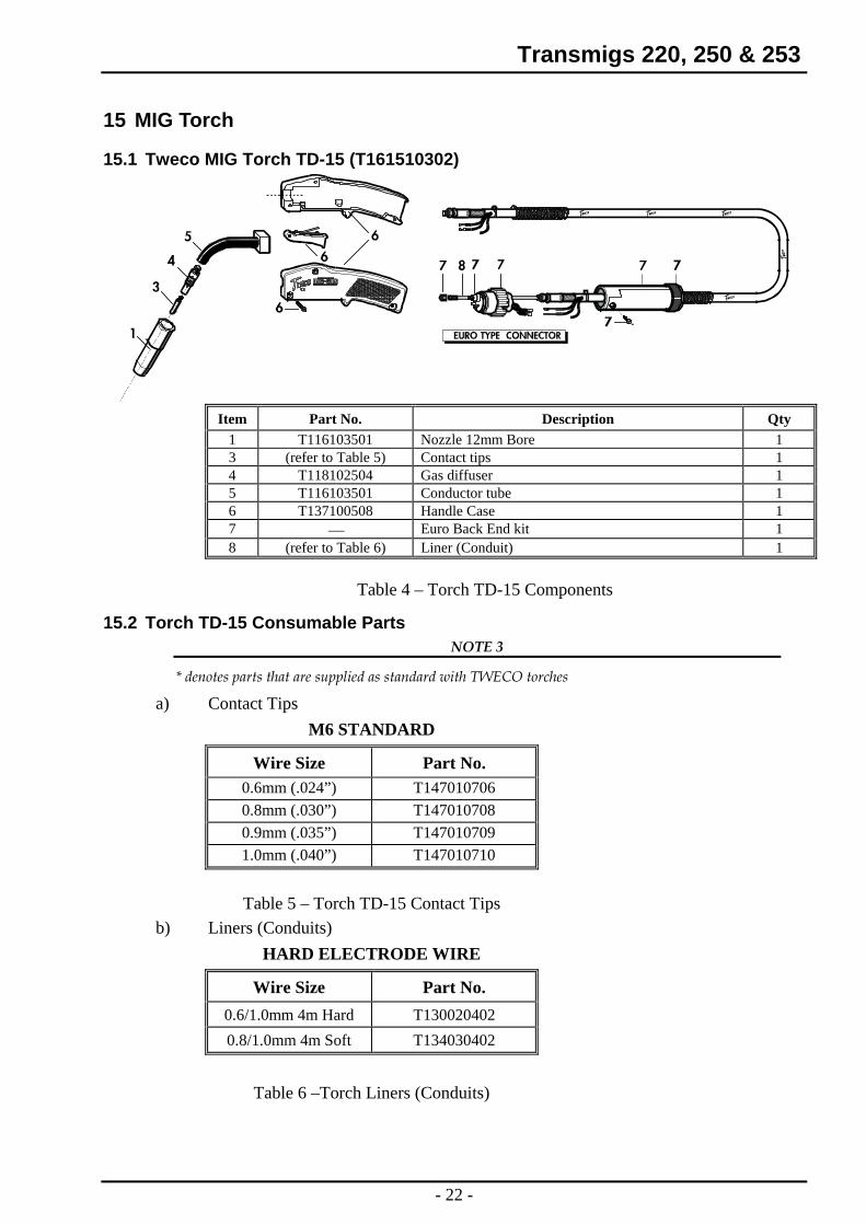
15.1 Tweco MIG Torch TD-15 (T161510302)
Item Part No. Description Qty
1 T116103501 Nozzle 12mm Bore 1 3 (refer to Table 5) Contact tips 1 4 T118102504 Gas diffuser 1 5 T116103501 Conductor tube 1 6 T137100508 Handle Case 1 7 Euro Back End kit 1 ⎯ 8 (refer to Table 6) Liner (Conduit) 1
Table 4 – Torch TD-15 Components
15.2 Torch TD-15 Consumable Parts NOTE 3
* denotes parts that are supplied as standard with TWECO torches
a) Contact Tips M6 STANDARD
Wire Size Part No. 0.6mm (.024”) T147010706 0.8mm (.030”) T147010708 0.9mm (.035”) T147010709 1.0mm (.040”) T147010710
Table 5 – Torch TD-15 Contact Tips
b) Liners (Conduits) HARD ELECTRODE WIRE
Wire Size Part No. 0.6/1.0mm 4m Hard T130020402 0.8/1.0mm 4m Soft T134030402
Table 6 –Torch Liners (Conduits)
- 22 -
Transmigs 220, 250 & 253
15.3 Installing A New Wire Conduit a) Be sure the MIG Torch cable is arranged in a straight line, free from twists, when
installing or removing a wire conduit. Remove the old conduit by first removing the MIG Torches nozzle, contact tip and gas diffuser. Then loosen Allen screws, where fitted, in the conductor tube and connector plug and pull the old wire conduit out of the cable assembly from the connector plug end.
b) To install a new wire conduit, first inspect the o-ring gas seal on the conduit for cuts or damage. Start from the connector plug end of the assembly and begin pushing the conduit through the connector plug, cable assembly and into the gun. If the conduit should lodge along the way, gently whip or work the cable assembly to aid forward movement.
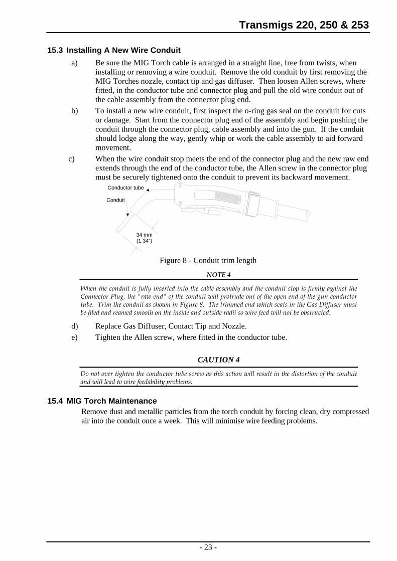
c) When the wire conduit stop meets the end of the connector plug and the new raw end extends through the end of the conductor tube, the Allen screw in the connector plug must be securely tightened onto the conduit to prevent its backward movement.
34 mm(1.34")
Conductor tube
Conduit
Figure 8 - Conduit trim length
NOTE 4
When the conduit is fully inserted into the cable assembly and the conduit stop is firmly against the Connector Plug, the "raw end" of the conduit will protrude out of the open end of the gun conductor tube. Trim the conduit as shown in Figure 8. The trimmed end which seats in the Gas Diffuser must be filed and reamed smooth on the inside and outside radii so wire feed will not be obstructed.
d) Replace Gas Diffuser, Contact Tip and Nozzle. e) Tighten the Allen screw, where fitted in the conductor tube.
CAUTION 4
Do not over tighten the conductor tube screw as this action will result in the distortion of the conduit and will lead to wire feedability problems.
15.4 MIG Torch Maintenance Remove dust and metallic particles from the torch conduit by forcing clean, dry compressed air into the conduit once a week. This will minimise wire feeding problems.
- 23 -
Transmigs 220, 250 & 253 16 Basic Welding Technique 16.1 Setting of the Power Source
The setting of the Transmig requires some practice by the operator, the welding Power Source having two control settings that have to balance. These are the Wirespeed control and the Voltage Control switch. The welding current is determined by the Wirespeed control, the current will increase with increased Wirespeed, resulting in a shorter arc. Less wire speed will reduce the current and lengthen the arc. Increasing the welding voltage hardly alters the welding current level, but lengthens the arc. By decreasing the voltage, a shorter arc is obtained with little change in welding current. When changing to a different electrode wire diameter, different control settings are required. A thinner electrode wire needs more Wirespeed to achieve the same current level. A satisfactory weld cannot be obtained if the wirespeed and voltage switch settings are not adjusted to suit the electrode wire diameter and dimensions of the work-piece. If the Wirespeed is too high for the welding voltage, “stubbing” will occur as the wire dips into the molten pool and does not melt. Welding in these conditions normally produces a poor weld due to lack of fusion. If, however, the welding voltage is too high, large drops will form on the end of the electrode wire, causing spatter. The correct setting of voltage and Wirespeed can be seen in the shape of the weld deposit and heard by a smooth regular arc sound.
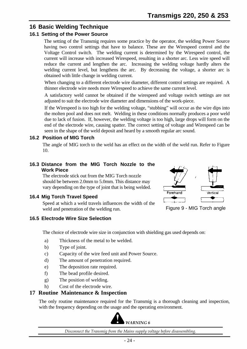
16.2 Position of MIG Torch The angle of MIG torch to the weld has an effect on the width of the weld run. Refer to Figure 10.
16.3 Distance from the MIG Torch Nozzle to the Work Piece The electrode stick out from the MIG Torch nozzle should be between 2.0mm to 5.0mm. This distance may vary depending on the type of joint that is being welded.
16.4 Mig Torch Travel Speed Speed at which a weld travels influences the width of the weld and penetration of the welding run.
Figure 9 - MIG Torch angle
16.5 Electrode Wire Size Selection
The choice of electrode wire size in conjunction with shielding gas used depends on:
a) Thickness of the metal to be welded. b) Type of joint. c) Capacity of the wire feed unit and Power Source. d) The amount of penetration required. e) The deposition rate required. f) The bead profile desired. g) The position of welding. h) Cost of the electrode wire.
17 Routine Maintenance & Inspection The only routine maintenance required for the Transmig is a thorough cleaning and inspection, with the frequency depending on the usage and the operating environment.
WARNING 6
Disconnect the Transmig from the Mains supply voltage before disassembling.
- 24 -
Transmigs 220, 250 & 253 Special maintenance is not necessary for the control unit parts in the Power Source. If these parts are damaged for any reason, replacement is recommended.
CAUTION 5
Do not blow air into the Power Source during cleaning. Blowing air into the Power Source can cause metal particles to interfere with sensitive electronic components and cause damage to the Power Source.
To clean the Power Source, disconnect it from the mains supply voltage then open the enclosure and use a vacuum cleaner to remove any accumulated dirt and dust. The Power Source should also be wiped clean. If necessary, solvents that are recommended for cleaning electrical apparatus may be used. Troubleshooting and repairing the Transmig should be carried out only by those who are familiar with electrical equipment.
WARNING 7
Do not attempt to diagnose or repair unless you have had training in electronic measurement and troubleshooting techniques.
18 Basic Troubleshooting The basic level of troubleshooting is which can be performed without special equipment or knowledge, and without removing the covers from the Power Source.
If major components are faulty, then the Power Source should be returned to an Accredited CIGWELD Service Agent for repair.
18.1 Solving Problems Beyond the Welding Terminals The general approach to fix Gas Metal Arc Welding (GMAW) problems is to start at the wire spool then work through to the MIG torch. There are two main areas where problems occur with GMAW:
a) Porosity When there is a gas problem the result is usually porosity within the weld metal. Porosity always stems from some contaminant within the molten weld pool which is in the process of escaping during solidification of the molten metal. Contaminants range from no gas around the welding arc to dirt on the work piece surface. Porosity can be reduced by checking the following points:
1. Gas cylinder contents and flow meter. - Ensure that the gas cylinder is not empty and the flow meter is correctly adjusted to 15 litres per minute.
2. Gas leaks. - Check for gas leaks between the regulator/cylinder connection and in the gas hose to the Power Source.
3. Internal gas hose in the Power Source. - Ensure that the hose from solenoid valve to Mig torch adaptor is connected and not fractured.
4. Welding in a windy environment. - Shield the weld area from the wind or increase the gas flow.
5. Welding dirty, oily, painted, oxidised or greasy plate.
- Clean contaminates off the plate
- 25 -
Transmigs 220, 250 & 253 6. Distance between the MIG torch
nozzle and the work piece. - Keep the distance between the MIG torch
nozzle and the work piece to a minimum. Refer to section 16.3 on page 24.
Ensure that the gas holes are not blocked and gas is exiting out of the torch nozzle. Refer to WARNING 6.
7. Maintain the MIG torch in good working order.
-
Do not restrict gas flow by allowing spatter to build up inside the Mig torch nozzle.
WARNING 8 Disengage the drive roll when testing for gas flow by ear.
b) Inconsistent wire feed
Wire feeding problems can be reduced by checking the following points:
1. Wire spool brake is too tight. - Feed roller driven by motor in the cabinet will slip.
2. Wire spool brake is too loose. - Wire spool can unwind and tangle.
3. Worn or incorrect feed roller size. - Use 'U' groove feed roll matched to the aluminium wire size you are welding. Use 'V' groove feed roll matched to the steel wire size you are welding. Use ‘knurled ’ groove feed roll matched to flux cored wire size you are welding.
4. Misalignment of inlet/outlet guides. - Wire will rub against the misaligned guides and reduces wire feedability.
5. Liner blocked with swarf. - Swarf is produced by wire passing over feed roll, if excessive pressure is applied to the pressure roller adjuster.
Swarf can also be produced by the wire passing through an incorrect feed roller groove shape or size.
Swarf is fed into the liner where it accumulates thus reducing wire feedability.
6. Incorrect or worn contact tip. - The contact tip transfers the weld current to the electrode wire. If the hole in the contact tip is to large then arcing may occur inside the contact tip resulting in the electrode wire jamming in the contact tip.
When using soft electrode wire such as aluminium it may become jammed in the contact tip due to expansion of the wire when heated. A contact tip designed for soft electrode wires should be used.
- 26 -

Transmigs 220, 250 & 253 7. Poor work lead contact to work piece. - If the work lead has a poor electrical
contact to the work piece then the connection point will heat up and result in a reduction of power at the arc.
8. Bent liner. - This will cause friction between the wire and the liner thus reducing wire feedability
18.2 Welding Problems FAULT CAUSE REMEDY
1 Undercut. A Welding arc voltage too high.
A Reduce voltage by reducing the voltage selection switch position or increase the wire feed speed.
B Incorrect torch angle B Adjust angle C Excessive heat input C Increase the torch travel speed
and/or reduce welding current by reducing the voltage selection switch position or reducing the wire feed speed.
2 Lack of penetration. A Welding current too low A Increase welding current by increasing wire feed speed and increasing voltage selection switch position.
B Joint preparation too narrow or gap too tight
B Increase joint angle or gap
C Shielding gas incorrect C Change to a gas which gives higher penetration
3 Lack of fusion. Voltage too low Increase voltage by increasing voltage selection switch position.
4 Excessive spatter. A Voltage too high A Lower voltage by reducing the voltage selection switch or increase wirespeed control.
B Voltage too low B Raise voltage by increasing the voltage selection switch or reduce wirespeed control.
5 Irregular weld shape. A Incorrect voltage and current settings. Convex, voltage too low. Concave, voltage too high.
A Adjust voltage and current by adjusting the voltage selection switch and the wirespeed control.
B Wire is wandering B Replace contact tip C Incorrect shielding gas C Check shielding gas. D Insufficient or excessive
heat input D Adjust the wirespeed control or
the voltage selection switch.
- 27 -
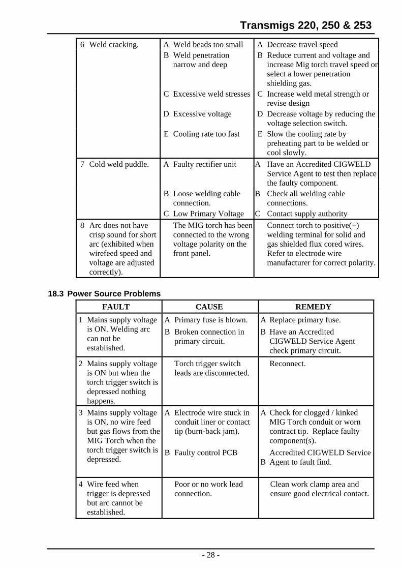
Transmigs 220, 250 & 253 6 Weld cracking. A Weld beads too small A Decrease travel speed B Weld penetration
narrow and deep B Reduce current and voltage and
increase Mig torch travel speed or select a lower penetration shielding gas.
C Excessive weld stresses C Increase weld metal strength or revise design
D Excessive voltage D Decrease voltage by reducing the voltage selection switch.
E Cooling rate too fast E Slow the cooling rate by preheating part to be welded or cool slowly.
7 Cold weld puddle. A Faulty rectifier unit A Have an Accredited CIGWELD Service Agent to test then replace the faulty component.
B Loose welding cable connection.
B Check all welding cable connections.
C Low Primary Voltage C Contact supply authority 8 Arc does not have
crisp sound for short arc (exhibited when wirefeed speed and voltage are adjusted correctly).
The MIG torch has been connected to the wrong voltage polarity on the front panel.
Connect torch to positive(+) welding terminal for solid and gas shielded flux cored wires. Refer to electrode wire manufacturer for correct polarity.
18.3 Power Source Problems
FAULT CAUSE REMEDY 1 Mains supply voltage
is ON. Welding arc can not be established.
A Primary fuse is blown. A Replace primary fuse. B Broken connection in
primary circuit. B Have an Accredited
CIGWELD Service Agent check primary circuit.
2 Mains supply voltage is ON but when the torch trigger switch is depressed nothing happens.
Torch trigger switch leads are disconnected.
Reconnect.
3 Mains supply voltage is ON, no wire feed but gas flows from the MIG Torch when the torch trigger switch is depressed.
A
Electrode wire stuck in conduit liner or contact tip (burn-back jam).
A
Check for clogged / kinked MIG Torch conduit or worn contract tip. Replace faulty component(s).
B Faulty control PCB Accredited CIGWELD Service Agent to fault find. B
4 Wire feed when trigger is depressed but arc cannot be established.
Poor or no work lead connection.
Clean work clamp area and ensure good electrical contact.
- 28 -
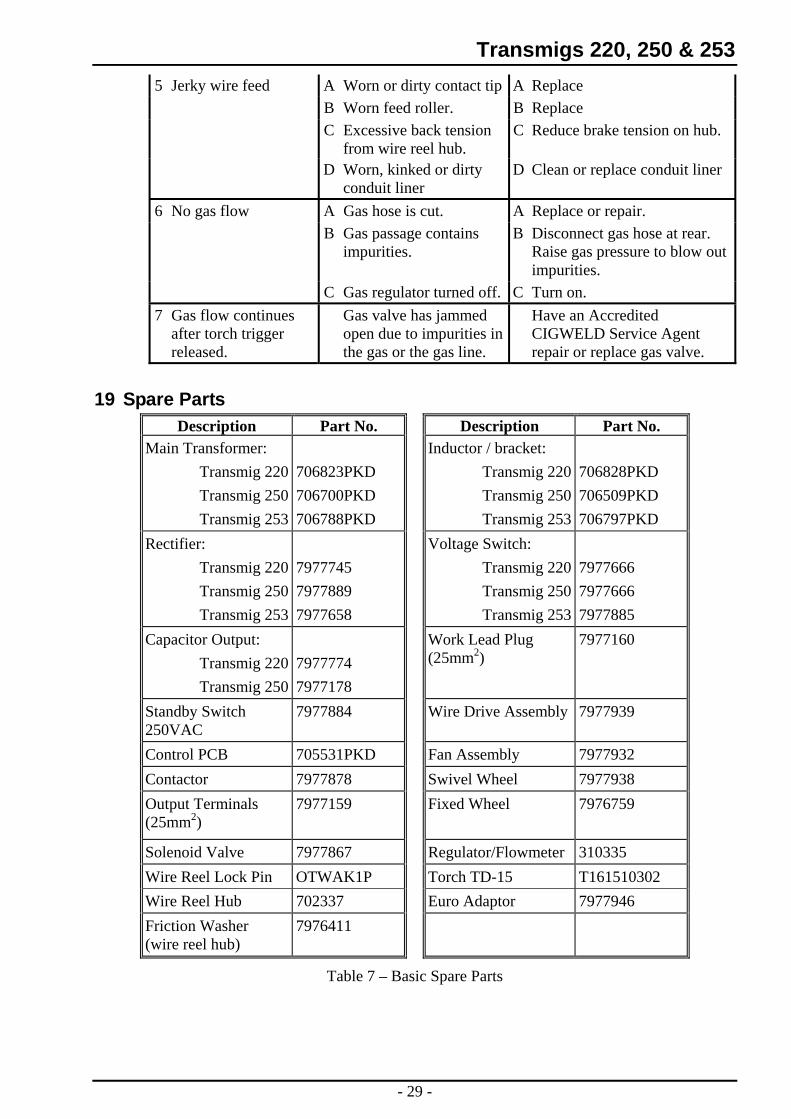
Transmigs 220, 250 & 253 5 Jerky wire feed A Worn or dirty contact tip A Replace B Worn feed roller. B Replace C Excessive back tension
from wire reel hub. C Reduce brake tension on hub.
D Worn, kinked or dirty conduit liner
D Clean or replace conduit liner
6 No gas flow A Gas hose is cut. A Replace or repair. B Gas passage contains
impurities. B Disconnect gas hose at rear.
Raise gas pressure to blow out impurities.
C Gas regulator turned off. C Turn on. 7 Gas flow continues
after torch trigger released.
Gas valve has jammed open due to impurities in the gas or the gas line.
Have an Accredited CIGWELD Service Agent repair or replace gas valve.
19 Spare Parts Description Part No. Description Part No.
Main Transformer: Inductor / bracket: Transmig 220 706823PKD Transmig 220 706828PKD Transmig 250 706700PKD Transmig 250 706509PKD Transmig 253 706788PKD Transmig 253 706797PKD
Rectifier: Voltage Switch: Transmig 220 7977745 Transmig 220 7977666 Transmig 250 7977889 Transmig 250 7977666 Transmig 253 7977658 Transmig 253 7977885
Capacitor Output: Work Lead Plug (25mm
7977160 2) Transmig 220 7977774
Transmig 250 7977178 Standby Switch 250VAC
7977884 Wire Drive Assembly 7977939
Control PCB 705531PKD Fan Assembly 7977932 Contactor 7977878 Swivel Wheel 7977938 Output Terminals (25mm
7977159 Fixed Wheel 7976759 2)
Solenoid Valve 7977867 Regulator/Flowmeter 310335 Wire Reel Lock Pin OTWAK1P Torch TD-15 T161510302 Wire Reel Hub 702337 Euro Adaptor 7977946 Friction Washer (wire reel hub)
7976411
Table 7 – Basic Spare Parts
- 29 -
Transmigs 220, 250 & 253
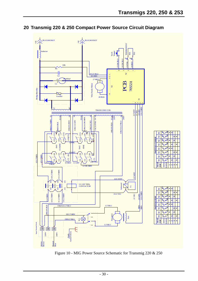
20 Transmig 220 & 250 Compact Power Source Circuit Diagram
LG 24V 50HzCONTACTOR
TRANS 250E COILFa
n m
otor
Varistor
Inductor
+
C1
C2
R1
Aux
Y1
Sole
noid
K1\
1
K1\
3
K1\
2
Torc
hTr
igge
r
TH1
THE
RM
OST
AT
-
+
Wir
e Fe
eder
Mot
or
PCB
Act
ive
A
Eart
h
Blue
Brow
n Gre
en\Y
ello
w
Neu
tral
N24
0V
88,000uF
Brid
ge R
ecti
fier
10K
PLUGSOCKET PLUGSOCKET
TH2
BR
NB
RN
20 ORN19 LT BLU
28 BLK
26 D
K B
LU
27 RED
25 D
K B
LU
24 R
ED
23 P
NK
13 L
T B
RN
14 G
RY
22 W
HT
21 V
IO
+VE
-VE
12
34
X3
13 2X
2
4
1234
X1
220VIn
put T
erm
inal
blo
ck
LT BLU
LT BLU
21A VIO
22 W
HT
21 V
IO
22A WHT
15B LT BLU
7055
31
(11)
(9)
(14)
(11)
(14)
(13)
(16)
(15)
(10)(16)
(12)
(10)
(12)
(15)(1
3)
(9)
S1
F1-S
2 F2 S3
F3-S
4 F4 S5F6
(3)
(4)
(1)
(2)
(5)
(6)
(7)
(8)
(3)
(4)
(2)
(1)
(5)
(6)
(8)
(7)
CO
AR
SE
FIN
E
SW1
SW2
[5]
[3]
[1]
[2]
[4]
[6]
F5-S
6
1 L
T BR
N
1A L
T B
RN
2 &
2A
PN
K
1E L
T BR
N
1H L
T BR
N
1F L
T B
RN
5 PNK
6 WHT
8 LT BRN
8&8A
LT
BR
N
9&9A
BL
K
9 BLK
10&
10A
RE
D
10 RED 11 GRY
11&
11A
GRY
12&
12A
DK
BR
N
12 DK BRN
13A VIO
13&
13A
VIO
14&
14A
BL
K
15&
15A
LT
BL
U
S7F7
0V 220V
240V
1G L
T BR
N
1D L
T B
RN
1C L
T B
RN
SL1
N
1B LT BRN
13 L
T B
RN
14 G
RY
14&
14A
BL
K 15&15A LT BLU
SWIT
CH
2 F
INE
TR
AN
TA
P
SWIT
CH
POSI
TIO
N
1 2 3 4
T2
S2T
2F2
T2
S2T
2F2
XX
XX
XX
XX
X
X
XXX
XX
X
1 265
43
8
97
11
1014
16
13
12
15
SWIT
CH
1 C
OA
RSE
TR
AN
TA
P
SWIT
CH
POSI
TIO
N
1 2 3 4
T2
S2T
2F2
T2
S2T
2F2
XX
XX
XX
XX
X
X
XXX
XX
X
1 265
43
8
97
11
1014
16
13
12
15
Figure 10 - MIG Power Source Schematic for Transmig 220 & 250
- 30 -

Transmigs 220, 250 & 253
21 Transmig 253 Compact Power Source Circuit Diagram
[ Not available at time of print ]
- 31 -

In the interest of continuous improvement, CIGWELD Pty. Ltd. reserves the right to change the specifications or design of any of its products without prior notice. © Copyright 1996
Distributed by: Manufacturer and Supplier of Welding Consumables and Equipment
CIGWELD Pty. Ltd. A.C.N. 007 226 815 Head Office: 71 Gower Street, Preston, Victoria, Australia 3072 Telephone: +613 9474 7400 Facsimile: (03) 9474 7391 Customer Service & Technical Support Line: 1300 654 674 International Enquiries: Telephone +61 3 9474 7508 Facsimile: +61 3 9474 7488