Embed Size (px)
DESCRIPTION
Manual tehnic
Citation preview
User and maintenance handbook
en
Mig
30 - 75 kWUser and maintenance handbook

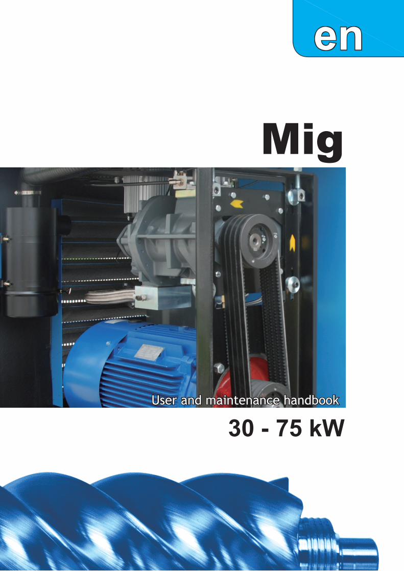
Electrical cable Ø38
Compressed air outlet G1 1/2'
Mig 30-45 kW
1
Fig.1
Cooling air outlet
Cooling air inlet
Motor air inlet
Cubicleair inlet
(Only Formula I 37)
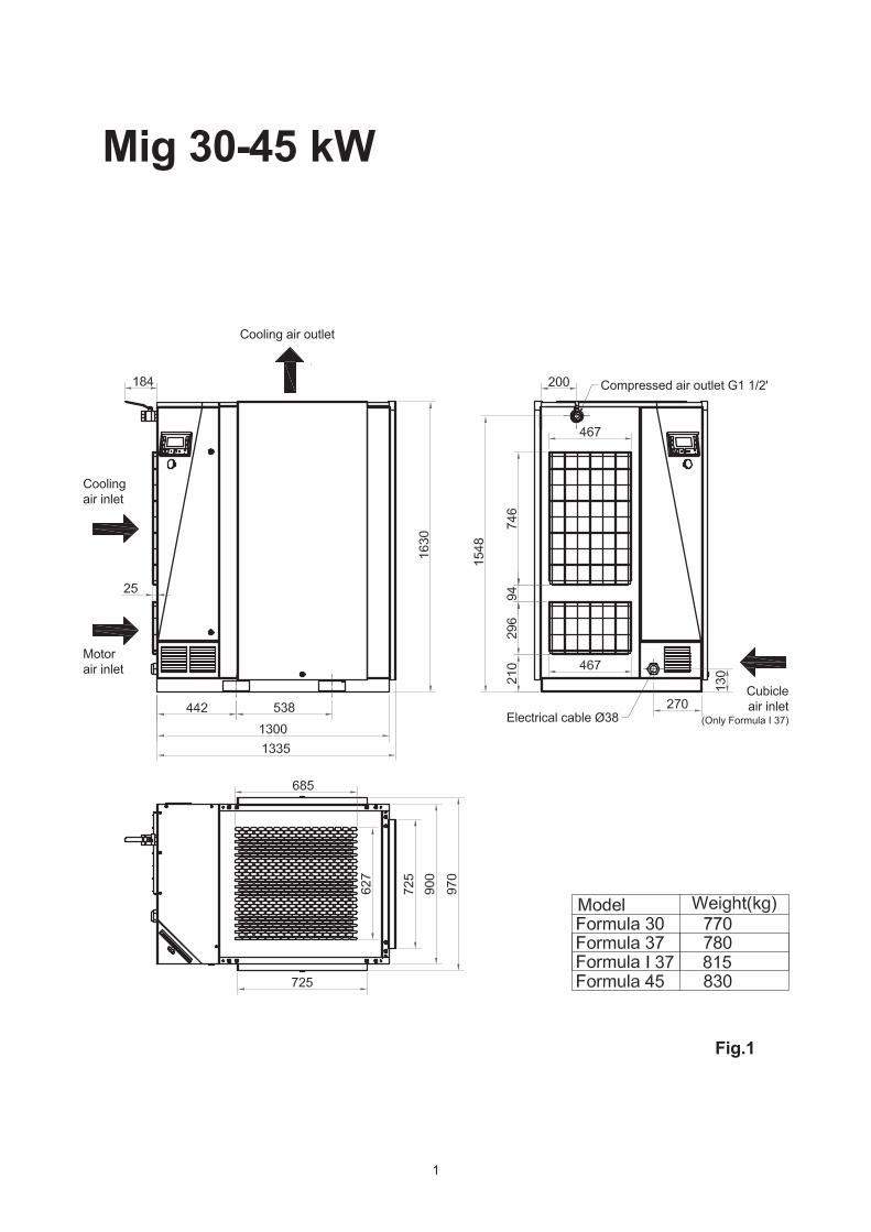
Mig 55-75 kW
2
Fig.2
Electrical cable Ø44
Compressed air outlet G2'
Cooling air outlet
Cooling air inlet
Motor air inlet
Cubicleair inlet
(Only Formula I 75)
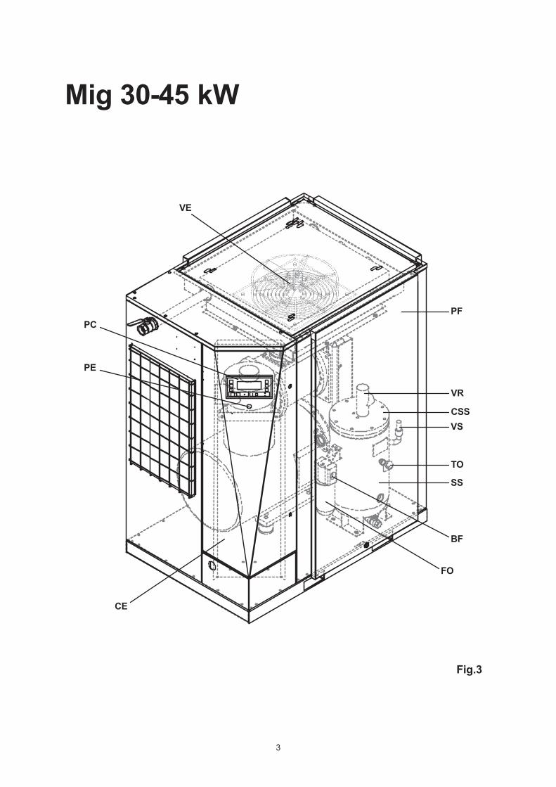
VE
PC
PE
CE
FO
BF
SS
TO
VSCSS
VR
PF
Mig 30-45 kW
3
Fig.3
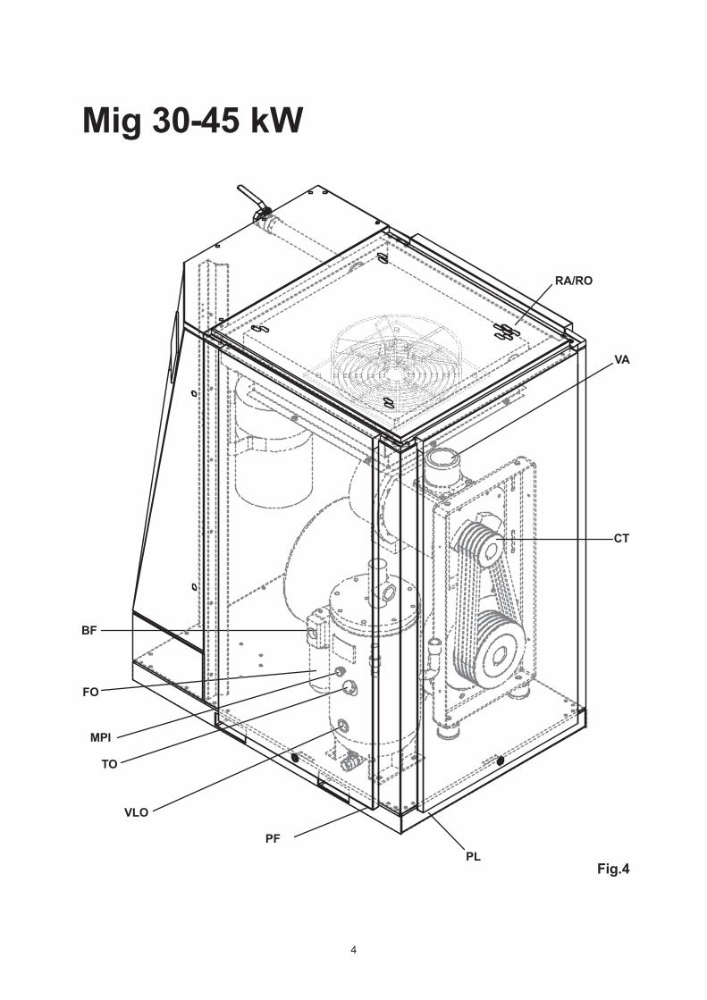
BF
FO
MPI
TO
VLO
PFPL
CT
VA
RA/RO
Mig 30-45 kW
4
Fig.4
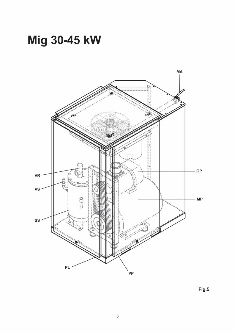
VR
VS
SS
PLPP
MP
GP
MA
Mig 30-45 kW
5
Fig.5
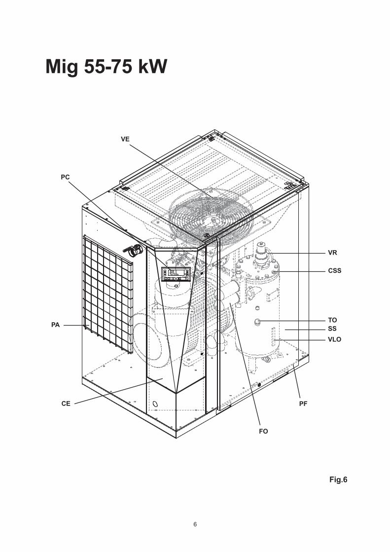
VE
PC
PA
CE
FO
PF
VLOSSTO
CSS
VR
Mig 55-75 kW
6
Fig.6
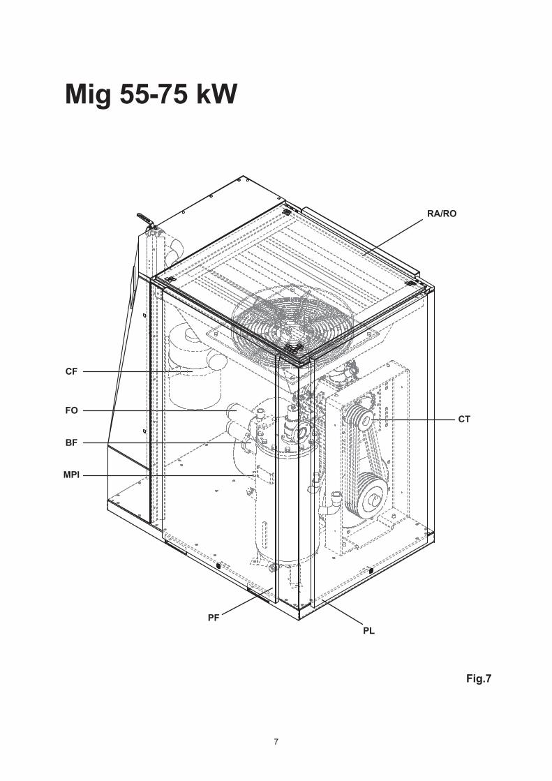
CF
FO
BF
MPI
PFPL
CT
RA/RO
Mig 55-75 kW
7
Fig.7
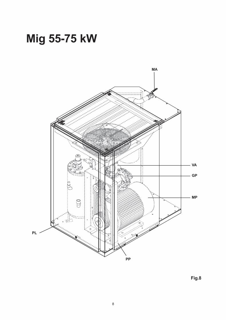
PL
PP
MP
GP
VA
MA
Mig 55-75 kW
8
Fig.8
9
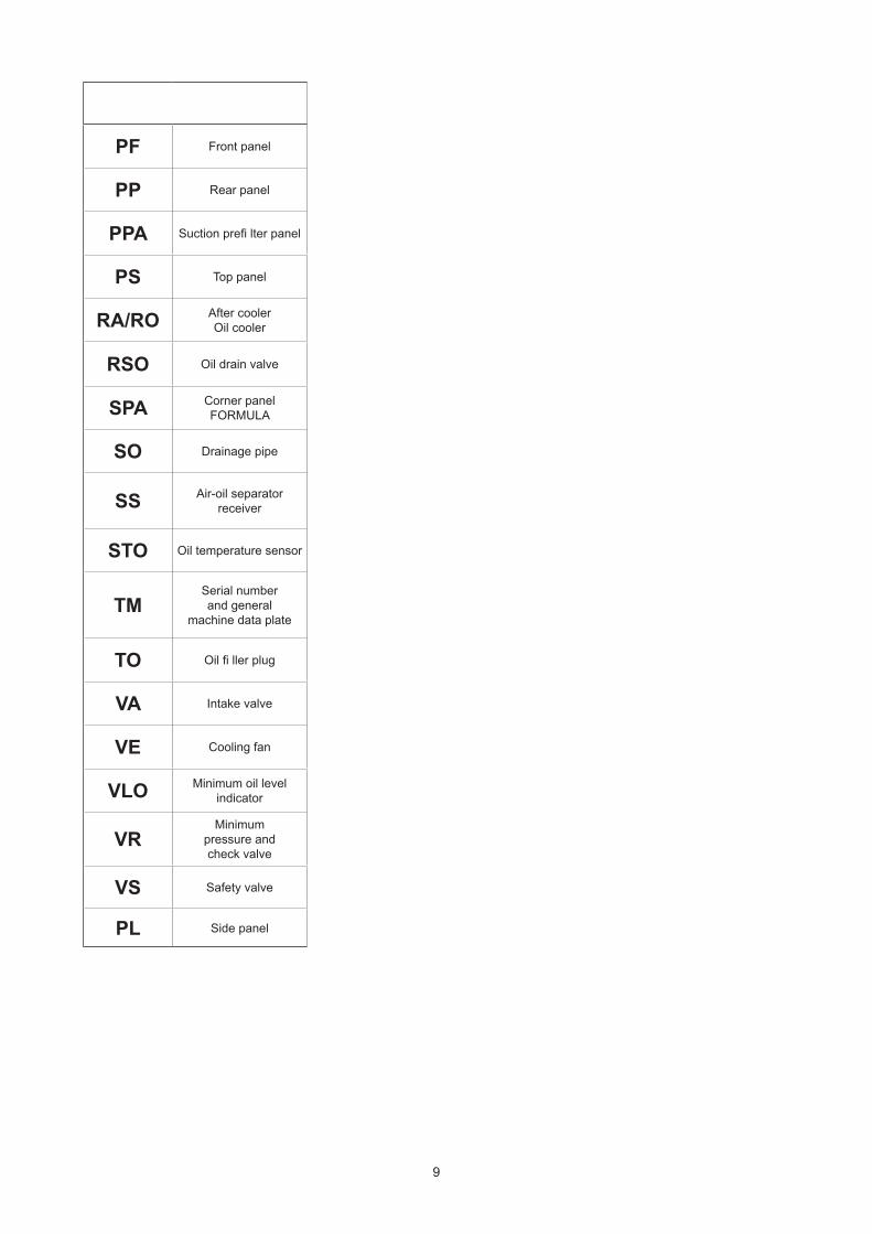
PF Front panel
PP Rear panel
PPA Suction prefi lter panel
PS Top panel
RA/RO After cooler Oil cooler
RSO Oil drain valve
SPA Corner panelFORMULA
SO Drainage pipe
SS Air-oil separator receiver
STO Oil temperature sensor
TMSerial number and general
machine data plate
TO Oil fi ller plug
VA Intake valve
VE Cooling fan
VLO Minimum oil level indicator
VRMinimum
pressure and check valve
VS Safety valve
PL Side panel
10
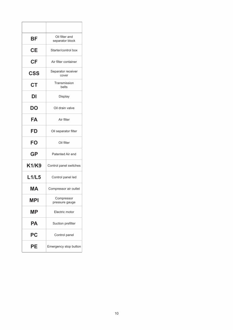
BF Oil filter andseparator block
CE Starter/control box
CF Air filter container
CSS Separator receiver cover
CT Transmission belts
DI Display
DO Oil drain valve
FA Air filter
FD Oil separator filter
FO Oil filter
GP Patented Air end
K1/K9 Control panel switches
L1/L5 Control panel led
MA Compressor air outlet
MPI Compressor pressure gauge
MP Electric motor
PA Suction prefilter
PC Control panel
PE Emergency stop button
en
11
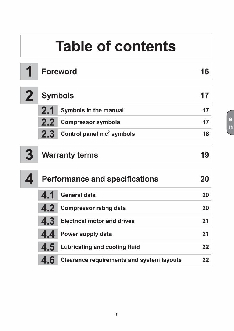
General data 20
Compressor rating data 20
Electrical motor and drives 21
Power supply data 21
Lubricating and cooling fluid 22
Clearance requirements and system layouts 22
1
2.12.22.3
4.14.24.34.44.54.6
2
34
Foreword 16
Symbols 17
Table of contents
Symbols in the manual 17
Compressor symbols 17
Control panel mc2 symbols 18
Warranty terms 19
Performance and specifications 20
en
5.15.2
7.17.2
7.2.17.2.2
7.4.17.4.2
7.4.2.1
7.37.4
6.16.2
5
6
7
6.36.46.5
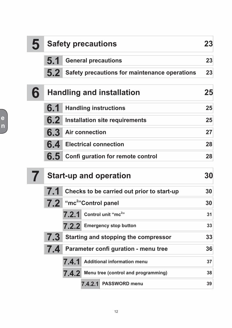
Additional information menu 37
Menu tree (control and programming) 38
Safety precautions 23
Handling and installation 25
Start-up and operation 30
General precautions 23
Safety precautions for maintenance operations 23
Handling instructions 25
Installation site requirements 25
Air connection 27
Electrical connection 28
Confi guration for remote control 28
Checks to be carried out prior to start-up 30
“mc2”Control panel 30
Control unit “mc2” 31
Emergency stop button 33
Starting and stopping the compressor 33
Parameter confi guration - menu tree 36
PASSWORD menu 39
12
en
7.4.2.2
7.4.2.3
7.4.2.4
7.4.2.5
7.4.2.6
7.4.2.7
7.4.2.8
7.5
9.4
9.5
9.6
9.19.29.3
9.79.89.9
89
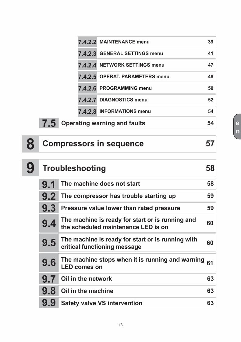
MAINTENANCE menu 39
GENERAL SETTINGS menu 41
NETWORK SETTINGS menu 47
OPERAT. PARAMETERS menu 48
PROGRAMMING menu 50
DIAGNOSTICS menu 52
INFORMATIONS menu 54
Operating warning and faults 54
Compressors in sequence 57
Troubleshooting 58
The machine does not start 58
The compressor has trouble starting up 59
Pressure value lower than rated pressure 59
Oil in the network 63
Oil in the machine 63
Safety valve VS intervention 63
The machine is ready for start or is running and the scheduled maintenance LED is on
The machine is ready for start or is running with critical functioning message
The machine stops when it is running and warning LED comes on
60
60
61
13
en
10
11
12
10.110.210.310.410.510.610.710.8
11.1
12.112.2
12.3
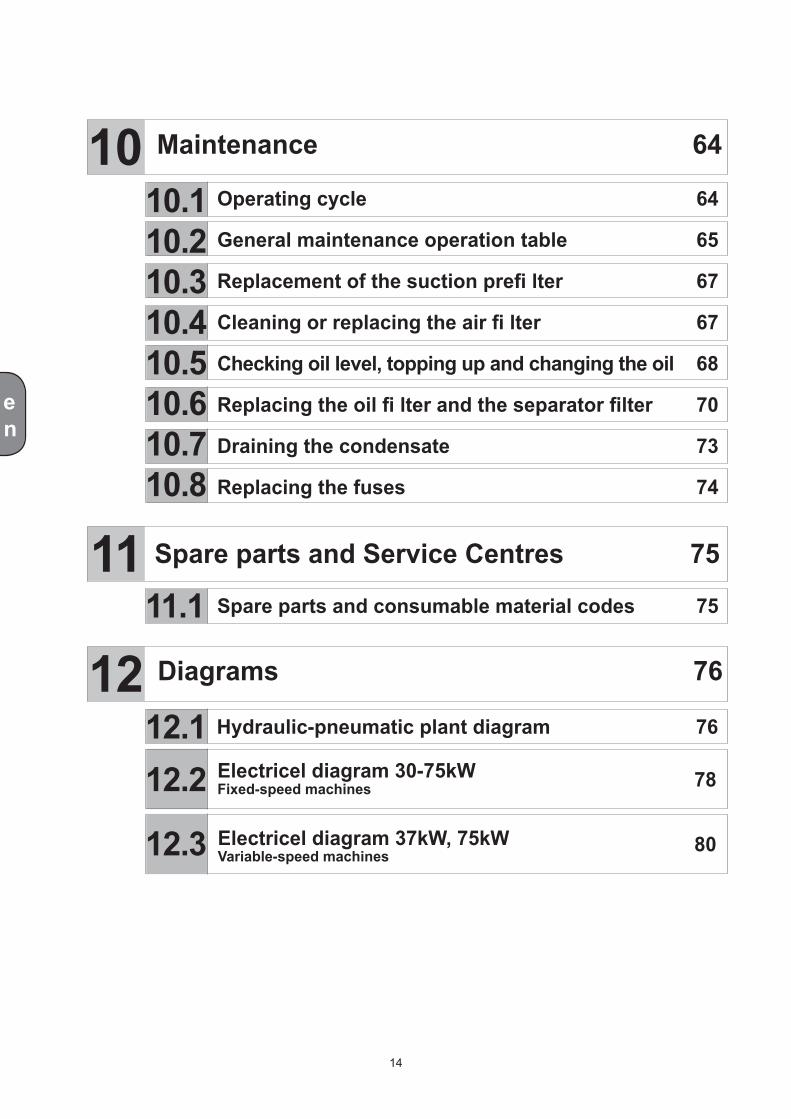
Hydraulic-pneumatic plant diagram 76
Maintenance 64
Operating cycle 64
General maintenance operation table 65
Replacement of the suction prefi lter 67
Cleaning or replacing the air fi lter 67
Checking oil level, topping up and changing the oil 68
Replacing the oil fi lter and the separator filter 70
Draining the condensate 73
Replacing the fuses 74
Spare parts and Service Centres 75
Diagrams 76
Spare parts and consumable material codes 75
Electricel diagram 30-75kWFixed-speed machines
Electricel diagram 37kW, 75kWVariable-speed machines
78
80
14
en
12.4
12.5
12.6
12.7
Wiring diagram for component location 30 - 45 kWFixed-speed machines
Wiring diagram for component location 55 - 75 kWFixed-speed machines
Wiring diagram for component location 37 kWVariable-speed machines
Wiring diagram for component location 75 kWVariable-speed machines
82
83
84
85
15

en
1Dear Customer,Congratulations on buying this compressor and thank you for your confidence in our Company.
The machine in your possession is a lubricated rotary screw compressor, incorporating state-of-the-art compressed air technology. The FORMULA 30 - 75kW series screw compressors are characterised by high energy output and low noise.
Major features incorporated in the design phase include versatility of use, reliability, low running and mainte-nance costs, compact size, and top fl ight performance. This range of compressors has also been designed and constructed complying with the strict quality control standards that are one of the main features of all products manufactured at our plants.
The product is CE approved and complies with current European Directives.
The compressor must be installed by specialized personnel of authorized service Centres.
Before starting the machine, read all sections of this handbook and always comply with the instructions provided which explain correct use and routine maintenance of the compressor and the precautions to be taken to ensure operator safety.
This manual must always accompany the compressor so that the documentation is always available to those who operate on the machine.
As concerns general maintenance, we recommend arranging a scheduled maintenance contract with our authorized Centres.
Foreword
Pag. 16 - Chap. 1 Foreword
2Symbols
en
P. 17 - Chap. 2 Symbols
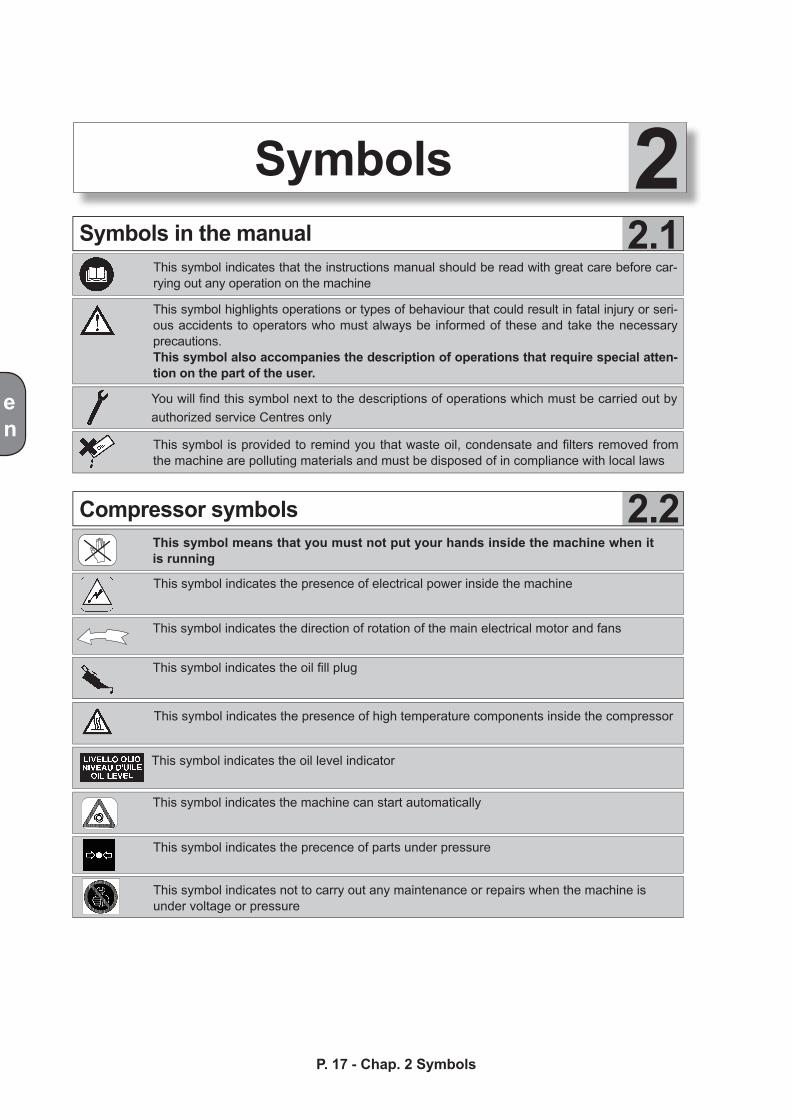
This symbol indicates that the instructions manual should be read with great care before car-rying out any operation on the machine
You will find this symbol next to the descriptions of operations which must be carried out by authorized service Centres only
Compressor symbols
Symbols in the manual
This symbol means that you must not put your hands inside the machine when it is running
This symbol highlights operations or types of behaviour that could result in fatal injury or seri-ous accidents to operators who must always be informed of these and take the necessary precautions.This symbol also accompanies the description of operations that require special atten-tion on the part of the user.
This symbol is provided to remind you that waste oil, condensate and filters removed from the machine are polluting materials and must be disposed of in compliance with local laws
This symbol indicates the presence of electrical power inside the machine
This symbol indicates the direction of rotation of the main electrical motor and fans
This symbol indicates the oil fill plug
This symbol indicates not to carry out any maintenance or repairs when the machine is under voltage or pressure
This symbol indicates the machine can start automatically
This symbol indicates the oil level indicator
This symbol indicates the presence of high temperature components inside the compressor
This symbol indicates the precence of parts under pressure
2.2
2.1
RESET
ESC
+-
en
P. 18 - Chap. 2 SymbolsP. 17 - Chap. 2 Symbols
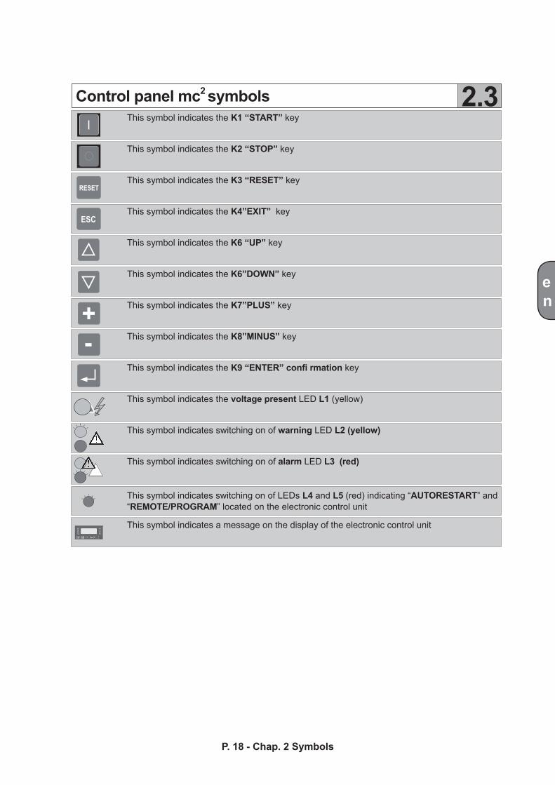
This symbol indicates the K1 “START” key
This symbol indicates the K2 “STOP” key
This symbol indicates the K3 “RESET” key
This symbol indicates the K4”EXIT” key
This symbol indicates the K6 “UP” key
This symbol indicates the K6”DOWN” key
This symbol indicates the K7”PLUS” key
This symbol indicates the K8”MINUS” key
This symbol indicates the K9 “ENTER” confi rmation key
This symbol indicates the voltage present LED L1 (yellow)
This symbol indicates switching on of warning LED L2 (yellow)
This symbol indicates switching on of alarm LED L3 (red)
This symbol indicates switching on of LEDs L4 and L5 (red) indicating “AUTORESTART” and “REMOTE/PROGRAM” located on the electronic control unit
This symbol indicates a message on the display of the electronic control unit
Control panel mc2 symbols 2.3
The product was tested before delivery. The air end is guaranteed for twenty-four months and the remaining machine parts are guaranteed for twelve months from the date of the invoice.
The warranty is valid only if the purchaser has complied with contractual and administrative regulations and if the compressor has been installed and operated according to the instructions provided in this handbook.
The Customer is required to fill out all parts of the warranty card and send it within thirty days from the date of purchase (as attested by the postmark). According to the terms of the warranty, the Manufacturer undertakes only to repair or replace, free of charge, the product or parts of this found to be faulty following examination by the Manufacturer’s technical person-nel or authorised repair company. Labour and transport are, in any case, excluded from the clauses of this warranty, and they will therefore be charged to you.
The warranty, which excludes all and any liability for direct or indirect injury or damage, is restricted only to construction and manufacturing defects of machine components. The warranty does not include parts which, due to their specific use, are liable to wear and tear such as seals, belts, etc. and all consumables such as air filter, oil filter, oil separator filter, etc The warranty does not cover repairs due to damage caused by insuffi cient or incorrect maintenance or unsuitable application..
The warranty shall be null and void in the case of failure to comply with the instructions given in this handbook, use of non-original spares and scheduled maintenance carried out directly by the Customer without the related invoice for the original parts.
The information given in this handbook is for guidance purposes only and is not binding. The Manufacturer reserves the right to make any product modifications it considers necessary without prior notice.
en
P. 19 - Chap. 3 Warranty terms
3Warranty terms
TM
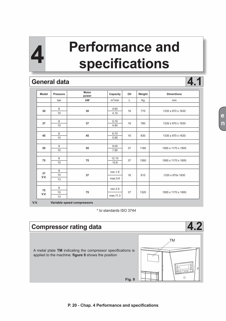
A metal plate TM indicating the compressor specifications is applied to the machine: figure 9 shows the position
Fig. 9
en
P. 20 - Chap. 4 Performance and specificationsP. 19 - Chap. 3 Warranty terms
Compressor rating data 4.2
General data 4.1
* to standards ISO 3744
4 Performance and specifications
V.V. Variable speed compressors
Model Pressure Motor power Capacity Oil Weight Dimentions
bar kW m3/min L Kg mm
308
304.60
16 770 1335 x 970 x 163010 4.10
378
375.70
16 780 1335 x 970 x 163010 4.90
458
456.70
16 830 1335 x 970 x 163010 5.90
558
559.00
37 1180 1585 x 1170 x 180010 7.90
758
7512.10
37 1260 1585 x 1170 x 180010 10.8
37V.V.
837
min.1.616 815 1335 x 970x 163010
max.5.613
75V.V.
875
min.3.537 1320 1585 x 1170 x 180010
max.11.313
en
P. 21 - Chap. 4 Performance and specifications
4.3
4.4
Electrical motors and drives
Power supply data
Compressor start-up
Two-pole, closed, three-phase asynchronous motor (rated speed of 3000 rpm at 50 Hz, 3600 rpm at 60 Hz, protection rating IP54, insulation class F, service class S1, reference MP in Figs. 5, 8)
Cooling fan
Four-pole, three-phase asynchronous electric fan, protection rating IP54, insulation class F (reference VE in Figs. 3, 6)
Drives
Compressor - motor: drive by means of removable taper bushing pulleys and toothed V-belts (reference CT in Figs. 4, 7)
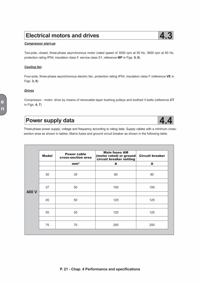
Three-phase power supply; voltage and frequency according to rating data. Supply cables with a minimum cross- section area as shown in tables. Mains fuses and ground circuit breaker as shown in the following table.
400 V
Model Power cablecross-section area
Main fuses AM(motor rated) or groundcircuit breaker setting
Circuit breaker
mm² A A
30 35 80 80
37 50 100 100
45 50 125 125
55 50 125 125
75 70 200 200
en
P. 22 - Chap. 4 Performance and specifications
4.5
4.6
Lubricated and cooling fluid
Clearance requirements and system layouts
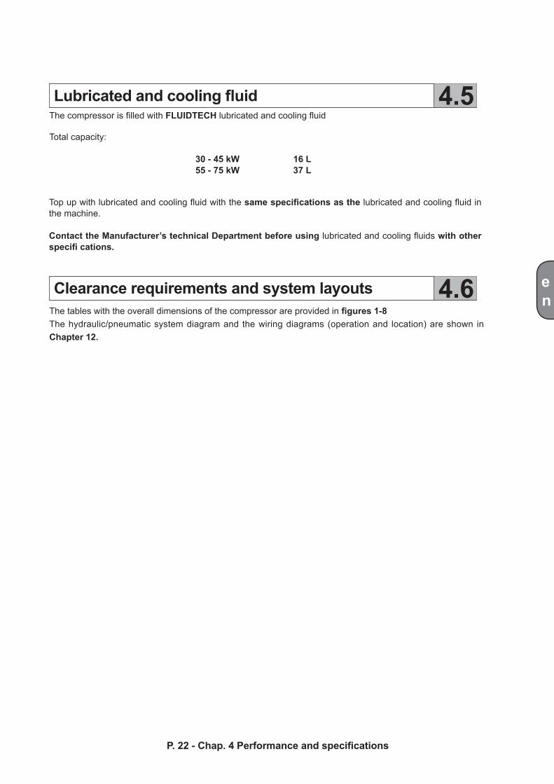
The compressor is filled with FLUIDTECH lubricated and cooling fluid
Total capacity:
30 - 45 kW 16 L55 - 75 kW 37 L
Top up with lubricated and cooling fluid with the same specifications as the lubricated and cooling fluid in the machine.
Contact the Manufacturer’s technical Department before using lubricated and cooling fluids with other specifi cations.
The tables with the overall dimensions of the compressor are provided in figures 1-8The hydraulic/pneumatic system diagram and the wiring diagrams (operation and location) are shown in Chapter 12.
en
P. 23 - Chap. 5 Safety precautions
5 Safety precautionsGeneral precautions
Safety precautions for maintenance operations
5.1
5.2
Use of the machine by unskilled personnel without adequate supervision is not allowed. Keep children and animals away from the working area.Do not direct compressed air jets towards yourself or other people.
Always use goggles to protect your eyes from objects which can be lifted by the jet of air.Never operate on the machine with bare feet or wet hands.
The compressor is designed solely to produce compressed air and cannot therefore be used for any other type of gas.
The compressed air produced by the machine cannot be used for respiratory assistance, pharmaceutical or sanitary purposes or in production plants where the output air comes into direct contact with food products unless an additional adequate air treatment system is employed
The air taken in by the compressor must be absolutely free of dust, vapours, explosive or flammable gases, solvents or powder paints and toxic fumes of any type.
Use of compressed air requires knowledge of and compliance with the safety precautions to be adopted for the individual applications (inflating, pneumatic tools, painting, washing with water-based detergents only, etc.).
Machine operation is fully automatic.
The machine carries out the various work cycles, as required by the user, according to the settings.After use, stop the machine and disconnect the main panel power.
Use of the machine for other purposes shall be considered as improper use and the Manufacturer shall not be liable for any resulting damage or injury.
Routine maintenance operations can be carried out by the user as described in this handbook.Only the use of original spare parts will guarantee long, safe and reliable service life of the equip-mentRefer to Chapter 10 for instructions on the operations that can be carried out by the user.
All major maintenance operations can be carried out only by the specialised personnel of authorised Service Centres
en
P. 24 - Chap. 5 Safety precautions
Disconnect the power supply, vent the air and wait for the machine to cool before performing any operation or removing the guards
All the air has been discharged from the machine when pressure gauge MPI shows zero pressure
After disconnecting the power, lock out the circuit breaker to prevent accidental start-up while operating on the compressor. Additionally, close the shut-off valve between the com-pressor and the line
No changes must be made to machine internal electrical, pneumatic, hydraulic circuits and/or to the set-tings. In particular, do not modify the maximum working pressure values and the valve settings, especially the safety valves.
Do not use solvents, flammable or toxic fl uids to clean the machine parts. Use alkaline detergents only. Never use detergents to clean the motor or the electrical/electronic components.
Do not weld or carry out mechanical machining operations on the receivers. If damaged or rusted, replace the parts, as they are subject to specifi c safety regulations.
At the end of each operation, refi t the guards carefully. Comply with the same precautions for initial start-up.
Remember that waste oil, condense and machine filters are polluting materials. Dispose of these products in compliance with local legislation
Careful scheduled maintenance will contribute to maintaining machine efficiency and user safety conditions in time.
en
P. 25 - Chap. 6 Handling and installation
6 Handling andinstallation
Handling instructions
Installation site requirements
6.1
6.2
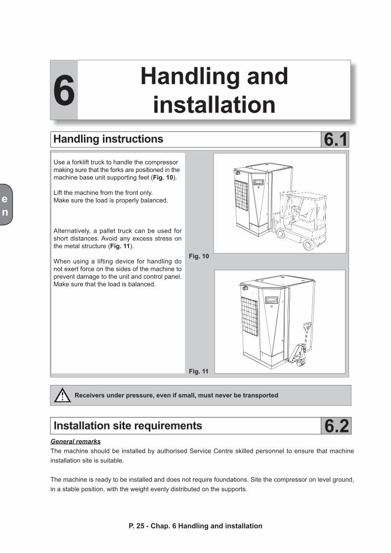
Receivers under pressure, even if small, must never be transported
General remarksThe machine should be installed by authorised Service Centre skilled personnel to ensure that machine installation site is suitable.
The machine is ready to be installed and does not require foundations. Site the compressor on level ground, in a stable position, with the weight evenly distributed on the supports.
Use a forklift truck to handle the compressormaking sure that the forks are positioned in themachine base unit supporting feet (Fig. 10).
Lift the machine from the front only.Make sure the load is properly balanced.
Alternatively, a pallet truck can be used for short distances. Avoid any excess stress on the metal structure (Fig. 11).
When using a lifting device for handling do not exert force on the sides of the machine to prevent damage to the unit and control panel. Make sure that the load is balanced.
Fig. 10
Fig. 11
min.3000
max5000
600
en
P. 26 - Chap. 6 Handling and installation
The environmental conditions that represent the operating range of the compressor are indicated below:- Maximum installation altitude (above sea level) ................................................................................:1000 m - Minimum ambient temperature..........................................................................................................:0° C- Maximum ambient temperature.........................................................................................................:+40° CMachine performance, as indicated in this handbook, is guaranteed only if the machine is installed at an altitude below the operating limit indicated.Contact the Manufacturer’s Technical Department in the case of particular environmental conditions.
Outdoor installation
Indoor installation
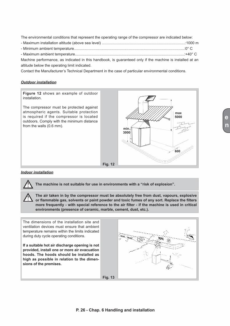
Figure 12 shows an example of outdoor installation.
The compressor must be protected against atmospheric agents. Suitable protection is required if the compressor is located outdoors. Comply with the minimum distance from the walls (0.6 mm).
The dimensions of the installation site and ventilation devices must ensure that ambient temperature remains within the limits indicated during duty cycle operating conditions.
If a suitable hot air discharge opening is not provided, install one or more air evacuation hoods. The hoods should be installed as high as possible in relation to the dimen-sions of the premises.
The machine is not suitable for use in environments with a “risk of explosion”.
The air taken in by the compressor must be absolutely free from dust, vapours, explosive or flammable gas, solvents or paint powder and toxic fumes of any sort. Replace the filters more frequently - with special reference to the air filter - if the machine is used in critical environments (presence of ceramic, marble, cement, dust, etc.).
Fig. 12
Fig. 13
500
1000
en
Air connection 6.3
P. 27 - Chap. 6 Handling and installation
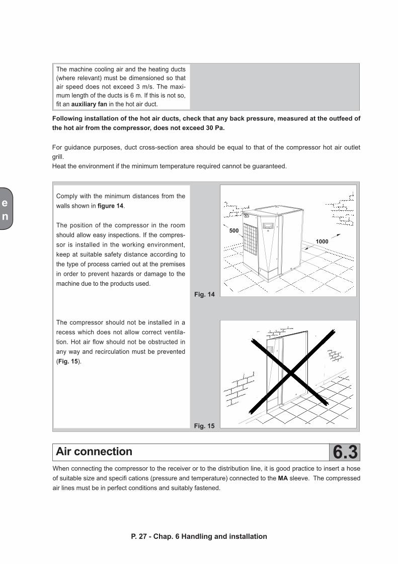
The machine cooling air and the heating ducts (where relevant) must be dimensioned so that air speed does not exceed 3 m/s. The maxi-mum length of the ducts is 6 m. If this is not so, fit an auxiliary fan in the hot air duct.
Following installation of the hot air ducts, check that any back pressure, measured at the outfeed of the hot air from the compressor, does not exceed 30 Pa.
For guidance purposes, duct cross-section area should be equal to that of the compressor hot air outlet grill.Heat the environment if the minimum temperature required cannot be guaranteed.
Comply with the minimum distances from the walls shown in figure 14.
The position of the compressor in the room should allow easy inspections. If the compres-sor is installed in the working environment, keep at suitable safety distance according to the type of process carried out at the premises in order to prevent hazards or damage to the machine due to the products used.
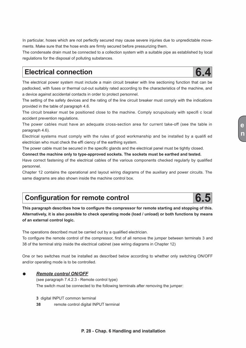
The compressor should not be installed in a recess which does not allow correct ventila-tion. Hot air flow should not be obstructed in any way and recirculation must be prevented (Fig. 15).
When connecting the compressor to the receiver or to the distribution line, it is good practice to insert a hose of suitable size and specifi cations (pressure and temperature) connected to the MA sleeve. The compressed air lines must be in perfect conditions and suitably fastened.
Fig. 14
Fig. 15
en
Electrical connection
Configuration for remote control
6.4
6.5
P. 28 - Chap. 6 Handling and installation
This paragraph describes how to configure the compressor for remote starting and stopping of this. Alternatively, it is also possible to check operating mode (load / unload) or both functions by means of an external control logic.
The operations described must be carried out by a qualified electrician.To configure the remote control of the compressor, first of all remove the jumper between terminals 3 and 38 of the terminal strip inside the electrical cabinet (see wiring diagrams in Chapter 12)
One or two switches must be installed as described below according to whether only switching ON/OFF and/or operating mode is to be controlled.
In particular, hoses which are not perfectly secured may cause severe injuries due to unpredictable move-ments. Make sure that the hose ends are firmly secured before pressurizing them. The condensate drain must be connected to a collection system with a suitable pipe as established by local regulations for the disposal of polluting substances.
The electrical power system must include a main circuit breaker with line sectioning function that can be padlocked, with fuses or thermal cut-out suitably rated according to the characteristics of the machine, and a device against accidental contacts in order to protect personnel.The setting of the safety devices and the rating of the line circuit breaker must comply with the indications provided in the table of paragraph 4.6. The circuit breaker must be positioned close to the machine. Comply scrupulously with specifi c local accident prevention regulations.The power cables must have an adequate cross-section area for current take-off (see the table in paragraph 4.6).Electrical systems must comply with the rules of good workmanship and be installed by a qualifi ed electrician who must check the effi ciency of the earthing system. The power cable must be secured in the specific glands and the electrical panel must be tightly closed.Connect the machine only to type-approved sockets. The sockets must be earthed and tested.Have correct fastening of the electrical cables of the various components checked regularly by qualified personnel.Chapter 12 contains the operational and layout wiring diagrams of the auxiliary and power circuits. The same diagrams are also shown inside the machine control box.
Remote control ON/OFF(see paragraph 7.4.2.3 - Remote control type)The switch must be connected to the following terminals after removing the jumper:
3 digital INPUT common terminal38 remote control digital INPUT terminal
en
LOAD/NO-LOAD remote control(see paragraph 7.4.2.3 - Remote control type)
The switch must be connected to the following terminals after removing the jumper: 3 digital INPUT common terminal38 remote control digital INPUT terminal
ON/OFF - LOAD/NO-LOAD remote control(see paragraph 7.4.2.3 - Remote control type)
Two switches must be used for this configuration.The switches must be connected to the terminals after removing the jumper:
ON/OFF SWITCH3 digital INPUT common terminal38 remote control digital INPUT terminal
LOAD / NO-LOAD START SWITCH3 digital INPUT common terminal39 remote control digital INPUT terminal
Following modifications to the wiring, the remote control must be configured as explained in paragraph 7.4.2.3 - Local/remote /program control - Remote control type
P. 29 - Chap. 6 Handling and installation
en
P. 30 - Chap. 7 Start-up and operation
7Start-up and operationChecks to be carried out prior to start-up
“mc2” Control panel
7.1
7.2
N.B.: The Customer is responsible for installing the machine and making the required electrical and air connections.
Initial system start-up must be carried out by skilled personnel who will make the various checks required and follow the respective instructions.
Each machine was thoroughly tested at the plant before shipping. You should monitor the compressor during the first hours of operations to check for faults.
Follow the installation prescriptions given in chapters 5 and 6 Remove all packaging materials and tools Connect the compressor to the distribution line as shown in paragraphs 6.2 and 6.3 Check the oil level in the receiver: see paragraph 10.5. If the level is low, top up with lubricating oil of suitable specifications Check for correspondence between the compressor plate data with the actual specifi cations of the electrical system. A variation of ± 10% with respect to the rated value is allowed Connect the machine to the electrical system as described in paragraph 6.4
With regard to electrical connection, the voltage phase sequence is extremely important as it determines the direction of rotation which must comply with that indicated in the adhesive label on the belt guard. Note that even a few seconds of incorrect rotation may cause serious damage. A phase sequence checking device to prevent mistakes is fitted in the electrical panel.
The machine is now ready to be started.
Before starting the machine read the following paragraph and chapter 10 on maintenance operations for in-depth knowledge of the machine.
The compressor is fitted with a “control panel” (reference PC figures 3, 6 ) for setting up and monitoring ma-chine operation. The operating parameters were entered by the Manufacturer during “testing”. The param-eters were tested for several hours in the various operating conditions.
The features offered by this electronic control system includes: Fully automatic compressor operation Real-time operating parameter display
RESET
K4
K5
K6
K1 K2
K7
K8
K9
L1 L3 L2 K3 L4
L5
en
P. 31 - Chap. 7 Start-up and operation
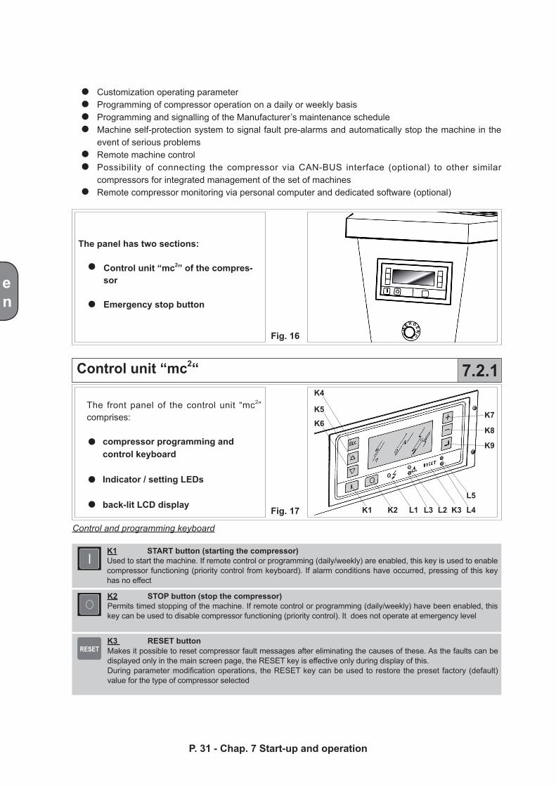
Customization operating parameter Programming of compressor operation on a daily or weekly basis Programming and signalling of the Manufacturer’s maintenance schedule Machine self-protection system to signal fault pre-alarms and automatically stop the machine in the event of serious problems Remote machine control Possibility of connecting the compressor via CAN-BUS interface (optional) to other similar compressors for integrated management of the set of machines Remote compressor monitoring via personal computer and dedicated software (optional)
The panel has two sections:
Control unit “mc2” of the compres-sor
Emergency stop button
Fig. 16
Fig. 17
Control unit “mc2“ 7.2.1
The front panel of the control unit “mc2” comprises:
compressor programming andcontrol keyboard
Indicator / setting LEDs
back-lit LCD display
Control and programming keyboard
K1 START button (starting the compressor)Used to start the machine. If remote control or programming (daily/weekly) are enabled, this key is used to enable compressor functioning (priority control from keyboard). If alarm conditions have occurred, pressing of this key has no effect
K2 STOP button (stop the compressor)Permits timed stopping of the machine. If remote control or programming (daily/weekly) have been enabled, this key can be used to disable compressor functioning (priority control). It does not operate at emergency level
K3 RESET buttonMakes it possible to reset compressor fault messages after eliminating the causes of these. As the faults can be displayed only in the main screen page, the RESET key is effective only during display of this.During parameter modification operations, the RESET key can be used to restore the preset factory (default) value for the type of compressor selected
ESC
+
-en
P. 32 - Chap. 7 Start-up and operation
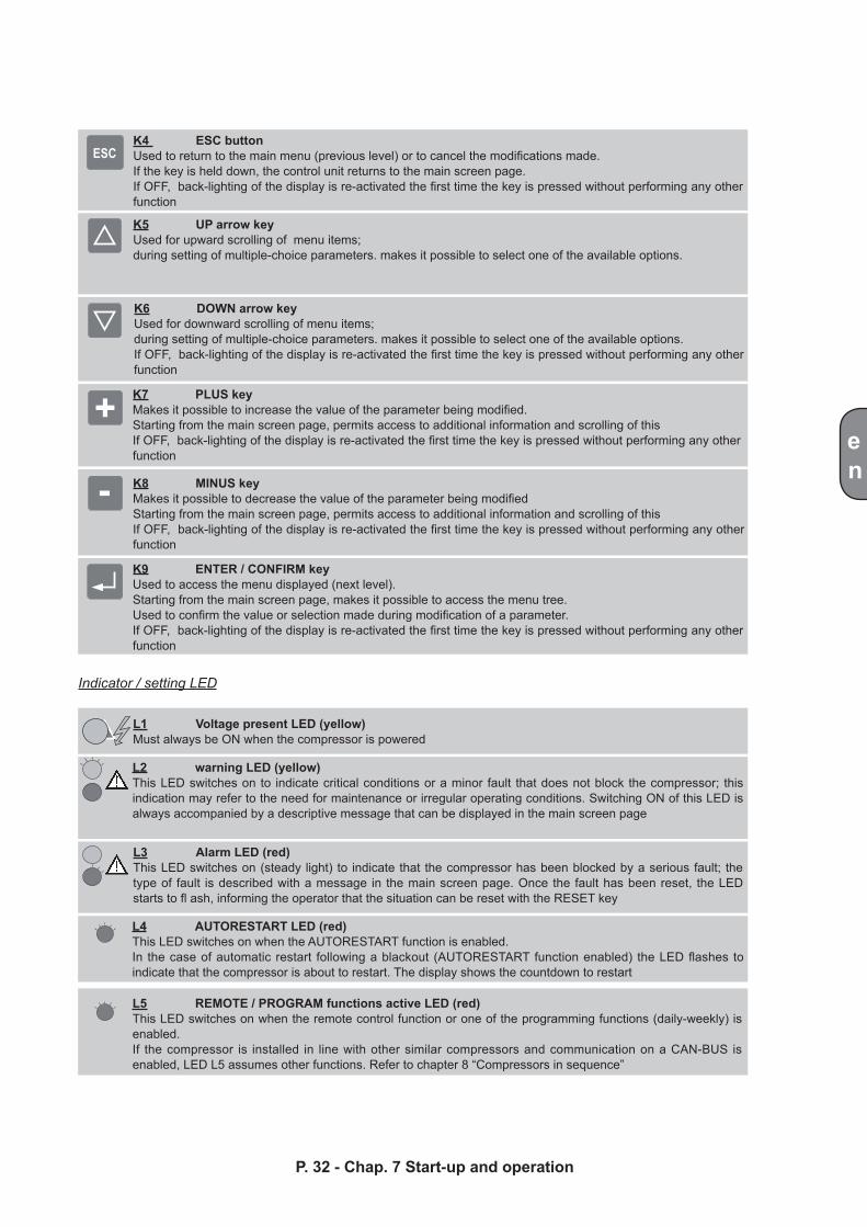
K4 ESC buttonUsed to return to the main menu (previous level) or to cancel the modifications made. If the key is held down, the control unit returns to the main screen page. If OFF, back-lighting of the display is re-activated the first time the key is pressed without performing any other function
K5 UP arrow keyUsed for upward scrolling of menu items; during setting of multiple-choice parameters. makes it possible to select one of the available options.
K6 DOWN arrow keyUsed for downward scrolling of menu items; during setting of multiple-choice parameters. makes it possible to select one of the available options.If OFF, back-lighting of the display is re-activated the first time the key is pressed without performing any other function
K7 PLUS keyMakes it possible to increase the value of the parameter being modified.Starting from the main screen page, permits access to additional information and scrolling of thisIf OFF, back-lighting of the display is re-activated the first time the key is pressed without performing any other function
K8 MINUS keyMakes it possible to decrease the value of the parameter being modifiedStarting from the main screen page, permits access to additional information and scrolling of thisIf OFF, back-lighting of the display is re-activated the first time the key is pressed without performing any other function
K9 ENTER / CONFIRM keyUsed to access the menu displayed (next level).Starting from the main screen page, makes it possible to access the menu tree.Used to confirm the value or selection made during modification of a parameter.If OFF, back-lighting of the display is re-activated the first time the key is pressed without performing any other function
Indicator / setting LED
L1 Voltage present LED (yellow)Must always be ON when the compressor is powered
L2 warning LED (yellow)This LED switches on to indicate critical conditions or a minor fault that does not block the compressor; this indication may refer to the need for maintenance or irregular operating conditions. Switching ON of this LED is always accompanied by a descriptive message that can be displayed in the main screen page
L3 Alarm LED (red)This LED switches on (steady light) to indicate that the compressor has been blocked by a serious fault; the type of fault is described with a message in the main screen page. Once the fault has been reset, the LED starts to fl ash, informing the operator that the situation can be reset with the RESET key
L4 AUTORESTART LED (red)This LED switches on when the AUTORESTART function is enabled.In the case of automatic restart following a blackout (AUTORESTART function enabled) the LED flashes to indicate that the compressor is about to restart. The display shows the countdown to restart
L5 REMOTE / PROGRAM functions active LED (red)This LED switches on when the remote control function or one of the programming functions (daily-weekly) is enabled.If the compressor is installed in line with other similar compressors and communication on a CAN-BUS is enabled, LED L5 assumes other functions. Refer to chapter 8 “Compressors in sequence”
1
2
<<<<mc2>>>>
Vers. Soft.: 1.0.0.1S/N: 000-00-01-00001
Pressure XX.X barTemperature XXX °CReady for start10:40 THU 25/05/2005
en
P. 33 - Chap. 7 Start-up and operation
Display
Emergency stop button
Starting and stopping the compressor
7.2.2
7.3
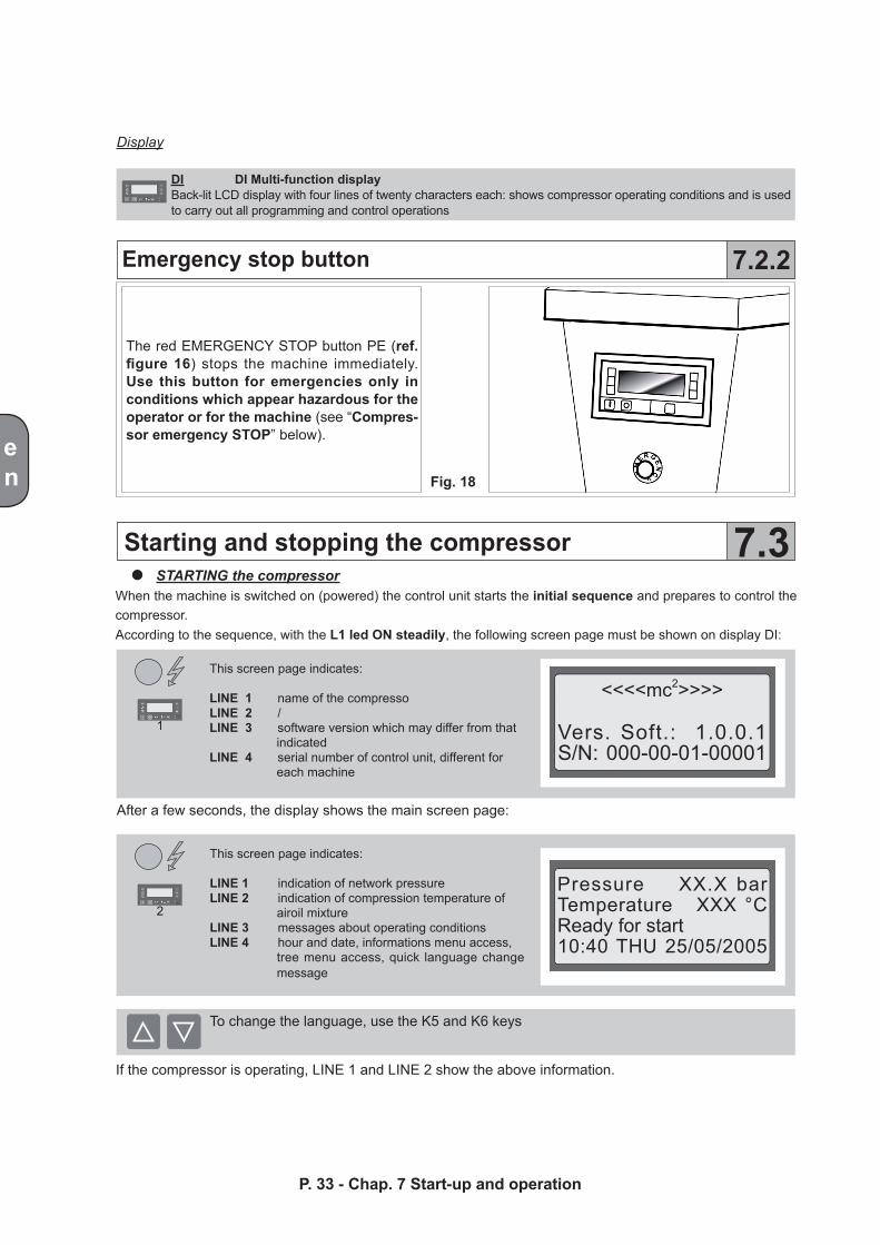
DI DI Multi-function displayBack-lit LCD display with four lines of twenty characters each: shows compressor operating conditions and is used to carry out all programming and control operations
The red EMERGENCY STOP button PE (ref. figure 16) stops the machine immediately. Use this button for emergencies only in conditions which appear hazardous for the operator or for the machine (see “Compres-sor emergency STOP” below).
Fig. 18
STARTING the compressorWhen the machine is switched on (powered) the control unit starts the initial sequence and prepares to control the compressor.According to the sequence, with the L1 led ON steadily, the following screen page must be shown on display DI:
This screen page indicates:
LINE 1 name of the compressoLINE 2 /LINE 3 software version which may differ from that
indicatedLINE 4 serial number of control unit, different for
each machine
After a few seconds, the display shows the main screen page:
This screen page indicates:
LINE 1 indication of network pressureLINE 2 indication of compression temperature of
airoil mixtureLINE 3 messages about operating conditionsLINE 4 hour and date, informations menu access,
tree menu access, quick language change message
To change the language, use the K5 and K6 keys
If the compressor is operating, LINE 1 and LINE 2 show the above information.
3
4
5
6
7
Stand by auto starthour-date
Stand by rem. com.hour-date
Stand by progr. com.hour-date
Starthour-date
Unload runhour-date
Load runhour-date
Starthour-date
en
P. 34 - Chap. 7 Start-up and operation
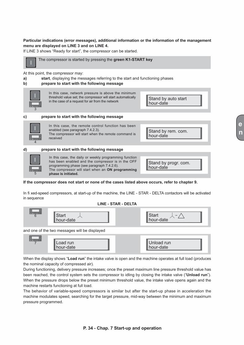
When the display shows “Load run” the intake valve is open and the machine operates at full load (produces the nominal capacity of compressed air).During functioning, delivery pressure increases; once the preset maximum line pressure threshold value has been reached, the control system sets the compressor to idling by closing the intake valve (“Unload run”). When the pressure drops below the preset minimum threshold value, the intake valve opens again and the machine restarts functioning at full load.The behavior of variable-speed compressors is similar but after the start-up phase in acceleration the machine modulates speed, searching for the target pressure, mid-way between the minimum and maximum pressure programmed.
Particular indications (error messages), additional information or the information of the management menu are displayed on LINE 3 and on LINE 4.If LINE 3 shows “Ready for start”, the compressor can be started.
The compressor is started by pressing the green K1-START key
At this point, the compressor may:a) start, displaying the messages referring to the start and functioning phasesb) prepare to start with the following message
In this case, network pressure is above the minimum threshold value set; the compressor will start automatically in the case of a request for air from the network
c) prepare to start with the following message
In this case, the remote control function has been enabled (see paragraph 7.4.2.3).The compressor will start when the remote command is received
d) prepare to start with the following message
In this case, the daily or weekly programming function has been enabled and the compressor is in the OFF programming phase (see paragraph 7.4.2.6). The compressor will start when an ON programming phase is initiated.
If the compressor does not start or none of the cases listed above occurs, refer to chapter 9.
In fi xed-speed compressors, at start-up of the machine, the LINE - STAR - DELTA contactors will be activated in sequence
LINE - STAR - DELTA
and one of the two messages will be displayed

8
9
10
11
Unload runhour-date
Stop in XXX sec.hour-date
Blowdown in XXX sec.hour-date
Start in XXX sec.hour-date
Unload runhour-date 04m 59s
Stand by auto starthour-date
en
P. 35 - Chap. 7 Start-up and operation
The compressor outputs the “Unload run” message, the machine never stops, always remaining available to restart production of compressed air immediately in the case of any request.
STOPPING the compressorMachine starting and stopping is timed.
Simply press the K2 button to stop the compressor
The compressor does not stop immediately but initiates a set of operations to stop the machine according to operating conditions when the STOP command is invoked. If, at the time of the STOP command, the compressor was operating at full load, the control unit sets the machine to unload run.
In fixed-speed compressors, display DI shows this count-down, at the end of which the motor is stopped.In variable-speed compressors the generic stop message is accompanied by deceleration of the motor.
If the K1-START key is pressed again before the preset timed restart time has passed, a new timing is shown on display D1 which indicates the time to compressor restart
This function prevents restarting the compressor when it is still pressurized, avoiding electrical motor verload.
At this point, the display shows this additional timing: during this phase, the compressor vents the pressure inside the separator reservoir preparing for subsequent restart.
For this reason, the percentage charge of the compressor is shown on the display.Variable-speed machines may also be characterized by idling in the case in which the minimum operating speed planned continues to produce excess air delivery in relation to that requested by the network.
During unload run, two cases may arise:
a) Setting of AUTOMATIC functioning (see paragraph 7.4.2.3):
The compressor outputs this message followed by a countdown.
At the end of the countdown, the compressor switches off, changing to “Stand-by auto start”, status, ready to restart in the case of a request for air
b) Setting of CONTIN. functioning (see paragraph 7.4.2.3):
RESET
12
13
14
EMERGENCY STOPcompress.-BlockR
Pressure XX.X barTemperature XXX °CReady for start10:40 THU 25/05/2005
ESCESC
+ -ADDIZIONAL
INFORMATIONS
Pressure XX.X barTemperature XXX °CR e a d y f o r s t a r t10:40 THU 25/05/2005
MENUTREE
7.4.1 7.4.2
en
P. 36 - Chap. 7 Start-up and operation
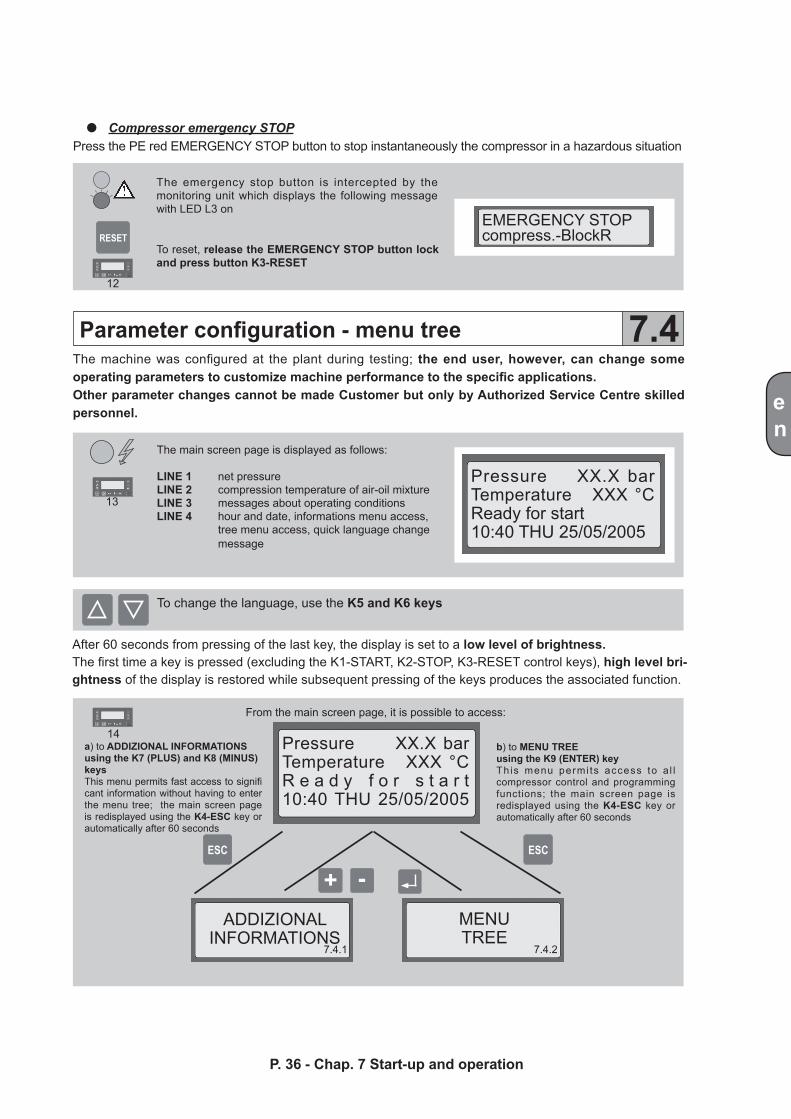
Compressor emergency STOPPress the PE red EMERGENCY STOP button to stop instantaneously the compressor in a hazardous situation
The emergency stop button is intercepted by the monitoring unit which displays the following message with LED L3 on
To reset, release the EMERGENCY STOP button lock and press button K3-RESET
Parameter configuration - menu tree 7.4The machine was configured at the plant during testing; the end user, however, can change some operating parameters to customize machine performance to the specific applications.Other parameter changes cannot be made Customer but only by Authorized Service Centre skilled personnel.
The main screen page is displayed as follows:
LINE 1 net pressureLINE 2 compression temperature of air-oil mixtureLINE 3 messages about operating conditionsLINE 4 hour and date, informations menu access, tree menu access, quick language change message
To change the language, use the K5 and K6 keys
After 60 seconds from pressing of the last key, the display is set to a low level of brightness. The first time a key is pressed (excluding the K1-START, K2-STOP, K3-RESET control keys), high level bri-ghtness of the display is restored while subsequent pressing of the keys produces the associated function.
a) to ADDIZIONAL INFORMATIONSusing the K7 (PLUS) and K8 (MINUS) keys This menu permits fast access to signifi cant information without having to enter the menu tree; the main screen page is redisplayed using the K4-ESC key or automatically after 60 seconds
b) to MENU TREEusing the K9 (ENTER) keyThis menu permi ts access to a l l compressor control and programming functions; the main screen page is redisplayed using the K4-ESC key or automatically after 60 seconds
From the main screen page, it is possible to access:
ESC
ESC
ESC
ESC
+ -
+ -
+ -
+ -
ESC
ESC
ESC
+ -
+ -
+ -
+ -
ESC
ESC
+ -
+ -
Menu A MAIN SCREEN PAGE
Pressure XX.X barTemperature XXX °CReady for starthour-date
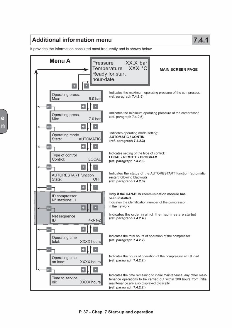
Indicates the maximum operating pressure of the compressor.(ref. paragraph 7.4.2.5)
Only if the CAN-BUS communication module has been installed.Indicates the identification number of the compressor in the network
ID compressorN° stazione: 1
Indicates the minimum operating pressure of the compressor. (ref. paragraph 7.4.2.5)
Indicates operating mode setting:AUTOMATIC / CONTIN.(ref. paragraph 7.4.2.3)
Indicates setting of the type of control: LOCAL / REMOTE / PROGRAM(ref. paragraph 7.4.2.3)
Indicates the status of the AUTORESTART function (automatic restart following blackout)(ref. paragraph 7.4.2.3)
Indicates the order in which the machines are started(ref. paragraph 7.4.2.4.)
Indicates the total hours of operation of the compressor(ref. paragraph 7.4.2.2)
Indicates the hours of operation of the compressor at full load(ref. paragraph 7.4.2.2.)
Indicates the time remaining to initial maintenance: any other main-tenance operations to be carried out within 300 hours from initial maintenance are also displayed cyclically(ref. paragraph 7.4.2.2.)
Operating press.Max: 8.0 bar
Operating press.Min: 7.0 bar
Operating modeState: AUTOMATIC
Type of controlControl: LOCAL
AUTORESTART functionState: OFF
Net sequenceID 4-3-1-2
Operating timetotal: XXXX hours
Operating timeon load: XXXX hours
Time to serviceoil: XXXX hours
en
P. 37 - Chap. 7 Start-up and operation
Additional information menu 7.4.1It provides the information consulted most frequently and is shown below.
ESC
ESC
ESC
ESC
ESC
ESC
ESC
ESC
ESC
Menu BMAIN SCREEN PAGE
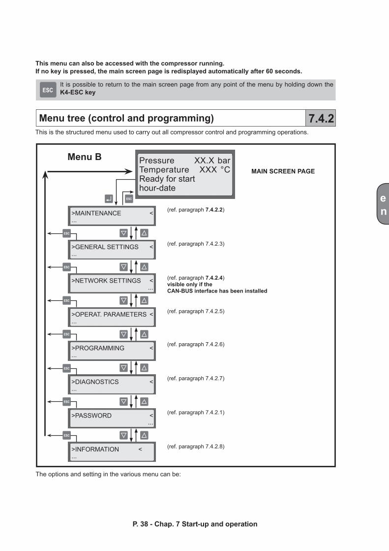
>MAINTENANCE <...
>GENERAL SETTINGS <...
>NETWORK SETTINGS < ...
>OPERAT. PARAMETERS <...
>PROGRAMMING <...
>DIAGNOSTICS <...
>PASSWORD < ...
>INFORMATION <...
Pressure XX.X barTemperature XXX °CReady for starthour-date
(ref. paragraph 7.4.2.2)
(ref. paragraph 7.4.2.3)
(ref. paragraph 7.4.2.4)visible only if the CAN-BUS interface has been installed
(ref. paragraph 7.4.2.5)
(ref. paragraph 7.4.2.6)
(ref. paragraph 7.4.2.7)
(ref. paragraph 7.4.2.1)
(ref. paragraph 7.4.2.8)
en
P. 38 - Chap. 7 Start-up and operation
Menu tree (control and programming) 7.4.2
This menu can also be accessed with the compressor running.If no key is pressed, the main screen page is redisplayed automatically after 60 seconds.
It is possible to return to the main screen page from any point of the menu by holding down the K4-ESC key
This is the structured menu used to carry out all compressor control and programming operations.
The options and setting in the various menu can be:
10
ESC
RESET
ESC
+ -
OPERATIONCOMPLETED
OPERATION ABORTED
ESC
ESC
Menu C
>PASSWORD <
>Enter password <
Enter password: 0000
en
P. 39 - Chap. 7 Start-up and operation
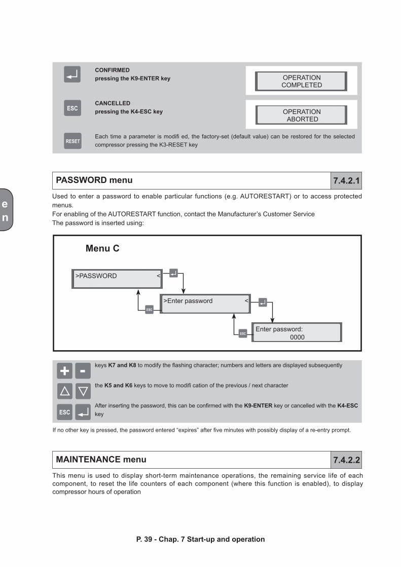
This menu is used to display short-term maintenance operations, the remaining service life of each component, to reset the life counters of each component (where this function is enabled), to display compressor hours of operation
CONFIRMEDpressing the K9-ENTER key
CANCELLEDpressing the K4-ESC key
Each time a parameter is modifi ed, the factory-set (default value) can be restored for the selected compressor pressing the K3-RESET key
PASSWORD menu
MAINTENANCE menu
7.4.2.1
7.4.2.2
keys K7 and K8 to modify the flashing character; numbers and letters are displayed subsequently
the K5 and K6 keys to move to modifi cation of the previous / next character
After inserting the password, this can be confirmed with the K9-ENTER key or cancelled with the K4-ESC key
If no other key is pressed, the password entered “expires” after five minutes with possibly display of a re-entry prompt.
Used to enter a password to enable particular functions (e.g. AUTORESTART) or to access protected menus.For enabling of the AUTORESTART function, contact the Manufacturer’s Customer ServiceThe password is inserted using:
ESC
ESC
ESC
ESC
ESC
ESC
ESC
ESC
ESC
ESC
ESC
ESC
ESC
only with access enabled
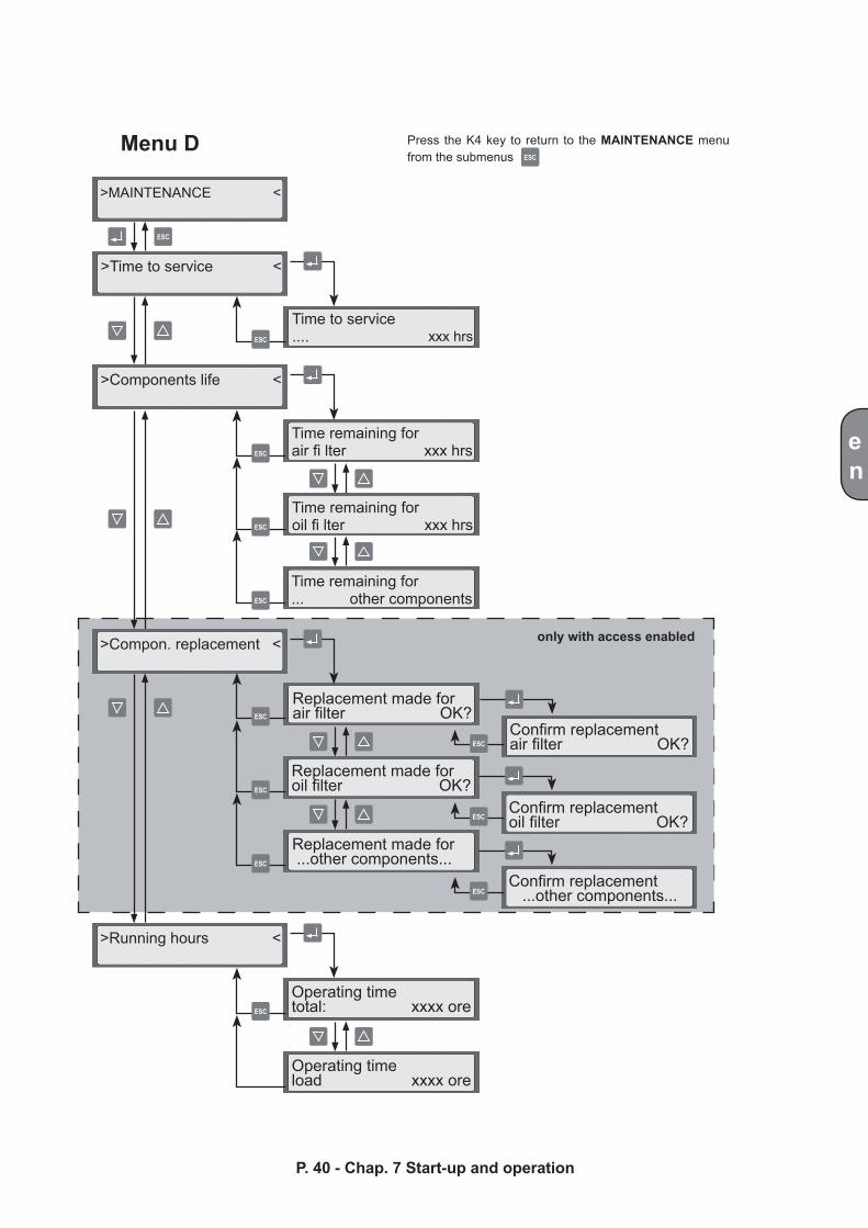
>MAINTENANCE <
>Time to service <
>Components life <
>Compon. replacement <
>Running hours <
Time to service .... xxx hrs
Time remaining for air fi lter xxx hrs
Time remaining for oil fi lter xxx hrs
Time remaining for ... other components
Replacement made for air filter OK?
Replacement made for oil filter OK?
Replacement made for ...other components...
Confirm replacement air filter OK?
Confirm replacement oil filter OK?
Confirm replacement ...other components...
Operating time total: xxxx ore
Operating time load xxxx ore
en
P. 40 - Chap. 7 Start-up and operation
Menu D Press the K4 key to return to the MAINTENANCE menu from the submenus
en
Time to service Makes it possible to check the first maintenance operation to be carried out on the compressor; the maintenance operations to be carried out 300 hours after this are also displayed. In this way, the user can schedule maintenance operations and, if necessary, decide whether to replace several components during the same maintenance operation
Components lifeindicates the remaining service life of each component that requires periodic maintenance
Compon. replacementIf the function is enabled, it makes it possible to reset the component life counters after maintenance
Running hoursIndicates compressor operating time (total running hours, running hours at full load)
A table with the schedule of only maintenance operations, managed from the control panel, is provided below
Maintenance periods may differ from those indicated.During installation, Service Centre personnel assess compressor operating conditions and if necessary modify the frequency of the operations.See paragraph 10.2 for the complete list of operations.
This menu allows to carry out the general settings of compressor operating confi guration with the exception of operating parameters (pressures, timings).
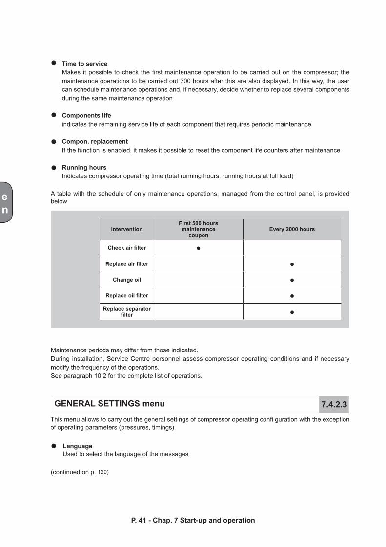
LanguageUsed to select the language of the messages
GENERAL SETTINGS menu 7.4.2.3
(continued on p. 120)
P. 41 - Chap. 7 Start-up and operation
InterventionFirst 500 hours maintenance
couponEvery 2000 hours
Check air filter ●
Replace air filter ●
Change oil ●
Replace oil filter ●Replace separator
filter ●
ESC
ESC
ESC
ESC
ESC
ESC
ESC
ESC
ESC
ESC
+ -
+ -
+ -
+ -
+ -
+ -
continued on p. 118
>GENERAL SETTINGS <
>Language <
>Measur. unit <
>Date and time <
>Display settings <
Select language: √ENGLISH
Select language: ..OTHER LANGUAGES..
Pressure unit Unit: bar
Temperature unit Unit: Cels.
Set date and time hh:mm day dd/mm/yyyy
Contrast Intensity: XXX%
Lighting ONBrightness: XXX%
Lighting OFFBrightness: XXX%
en
Menu E (1/3) Press the K4 key to return to the GENERAL SETTINGS menu from the submenus
P. 42 - Chap. 7 Start-up and operation
ESC
ESC
ESC
ESC
ESC
ESC
ESC
ESC
+ -
+ -
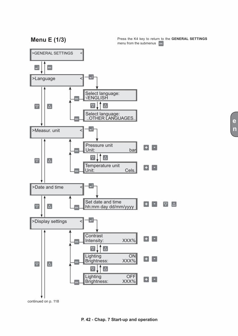
>Operating mode <
>Compress. control <
Operating mode √AUTOMATIC
Operating modeCONTIN
Compress. control√LOCAL
Compress. control REMOTE
Compress. control PROGRAM
Compress. control√NETWORK CONINUOUS
Compress. control NETWORK PROGRAM
en
P. 43 - Chap. 7 Start-up and operation
Press the K4 key to return to the GENERAL SETTINGS menu from the submenus
Menu E (2/3)continued from p. 117
Continued on p. 119
only if the CAN-BUS interface has been installed
ESC
ESC
ESC
ESC
ESC
ESC
ESC
ESC
ESC
ESC
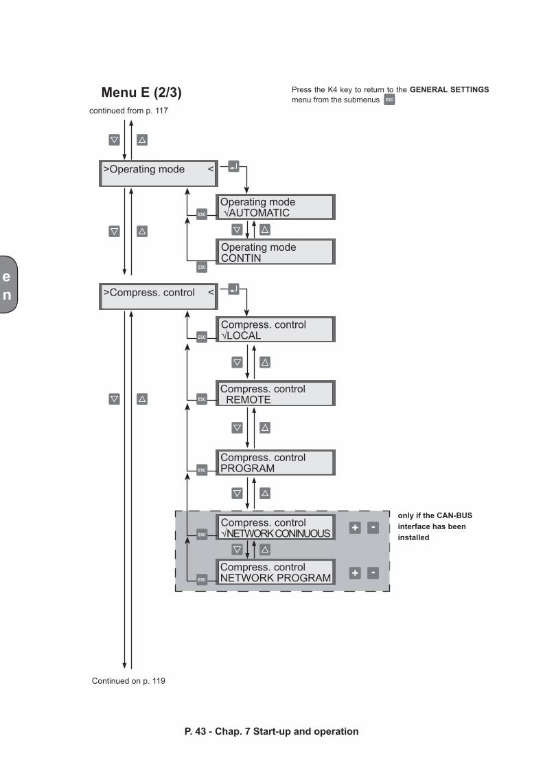
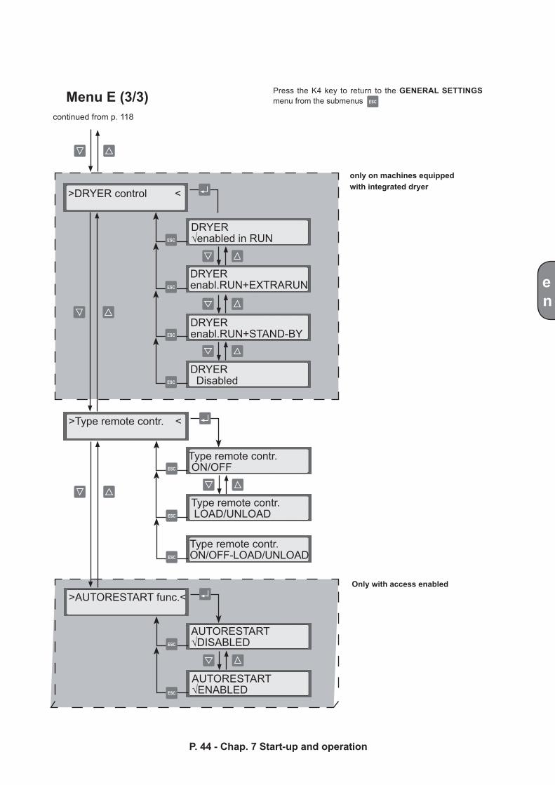
>DRYER control <
>AUTORESTART func. <
>Type remote contr. <
DRYER√enabled in RUN
DRYER enabl.RUN+EXTRARUN
DRYERenabl.RUN+STAND-BY
DRYER Disabled
Type remote contr. ON/OFF
Type remote contr. LOAD/UNLOAD
Type remote contr. ON/OFF-LOAD/UNLOAD
AUTORESTART√DISABLED
AUTORESTART √ENABLED
en
P. 44 - Chap. 7 Start-up and operation
Menu E (3/3)continued from p. 118
only on machines equipped with integrated dryer
Only with access enabled
Press the K4 key to return to the GENERAL SETTINGS menu from the submenus
ESC
+ -
en
P. 45 - Chap. 7 Start-up and operation
(continued from p.41)
Measur. unitUsed to set the measurement units for pressure and temperature
Date & timeUsed to set the current date and timeThe time and date are entered using:
the K7 and K8 keys to modify the flashing values
the K5 and K6 keys to move to modification of the previous / next character
After entry of the values, these can be confirmed with the K9-ENTER key or cancelled with the K4-ESC key.
Display settings Makes it possible to adjust the settings of the LCD display
Operating mode Compressor operating mode may be set AUTOMATIC or CONTINUOUS:AUTOMATIC: this is the setting used in most cases (factory setting). In this operating mode, idling is timed; at the end of the count, the compressor stops, preparing for subsequent automatic start-up (see also paragraph 7.3 STARTING the compressor). This promotes energy saving if there is no or a very low request for compressed air.
CONTINUOUS:this setting should be used in very particular applications characterized by a conside-rable variation in compressed air consumption combined with a reduced plant accumulation capacity. With this setting, the compressor starts unload run without ever stopping the motor and is therefore able to supply air continuously in the case of a request from the network. The system configured in this way is highly reactive. However, one of the drawbacks of this operating mode is that it entails higher power consumption due to the fact that the compressor is always running (see also paragraph 7.3 STARTING the compressor).
Compress. controlThis menu is used to select the compressor control method from the possible local / remote / program control options.If the compressor is equipped with a CAN-BUS interface, the network-continuous / network-program control options are also visible and can be selected.Compressor control can be set to:
LOCAL: this is the basic (factory) setting that permits control from the keyboard
REMOTE: with this setting, the compressor can be controlled by means of an external remote switch. For the electrical connections, refer to the following submenu (refer to the following paragraph “Type of remote control”)
PROGRAM: enables the daily or weekly programming set and enabled in the PROGRAMMING menu (see paragraph 7.4.2.6)
en
P. 46 - Chap. 7 Start-up and operation
NET-CONTINUOUS: this is the setting for control of a sequence of compressors, without daily/weekly program
NET-PROGRAM: this is the setting for control of a sequence of compressors according to the daily/weekly program set
Type of remote controlFor remote control, modifi cations must be made to the wiring of the compressor as described in paragraph 6.5.When compressor control is set to REMOTE (see previous submenu), three types of control methods are possible:
ON/OFF is the setting that makes it possible to control switching ON/OFF of the compressor. This is the factory setting (that most frequently used) which makes it possible to exploit the control logic of the compressor using the pressure signal measured locally by the machine
LOAD/UNLOAD is the setting that makes it possible to control full load and unload operation with an external control logic: in this case, the pressure signal measured by the compressor is ignored for the purposes of operating method control (the safety devices remain active)
ON/OFF - LOAD/UNLOAD is the setting that makes it possible to control both switching ON/OFF of the compressor and also operating mode. In this case also, an external control logic must be used as, for control purposes, the pressure signal is ignored (the safety devices remain active)
It should be remembered that control via the keyboard of the control unit always has priority over any remote control or any program: this means that, if remote control is to be effective, the START button must be pressed setting the compressor to “Stand-by rem. con.”. Similarly, the compressor can be stopped without any risk of remote restart of this by pressing the STOP key.
Therefore, to enable functioning with remote control:1) Make the modifications to the wiring connecting one / two switches as described in paragraph 6.52) Select REMOTE control3) Select the control method (ON/OFF, LOAD/UNLOAD, ON/OFF - LOAD/UNLOAD)4) Press the START key on the control unit to enable the compressor for remote control
ESC
ESC
ESC
ESC
ESC
ESC
ESC
+ -
+ -
+ -
+ -
+ -
+ -
+ -ESC
Press the K4 key to return to the NETWORK SETTINGS menu from the submenus
visible only if the CAN-BUS interface has been installed
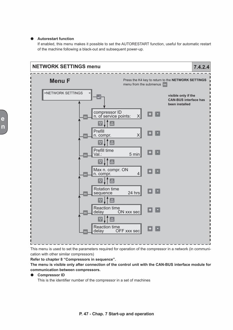
Menu F
>NETWORK SETTINGS <
compressor ID n. of service points: X
Prefill n. compr. X
Prefill time Val.: 5 min
Max n. compr. ON n. compr. 4
Rotation time sequence 24 hrs
Reaction time delay ON xxx sec
Reaction time delay OFF xxx sec
en
NETWORK SETTINGS menu 7.4.2.4
Autorestart functionIf enabled, this menu makes it possible to set the AUTORESTART function, useful for automatic restart of the machine following a black-out and subsequent power-up.
This menu is used to set the parameters required for operation of the compressor in a network (in communi-cation with other similar compressors)Refer to chapter 8 “Compressors in sequence”.The menu is visible only after connection of the control unit with the CAN-BUS interface module for communication between compressors.
Compressor ID This is the identifier number of the compressor in a set of machines
P. 47 - Chap. 7 Start-up and operation
en
OPERAT. PARAMETERS menu 7.4.2.5
P. 48 - Chap. 7 Start-up and operation
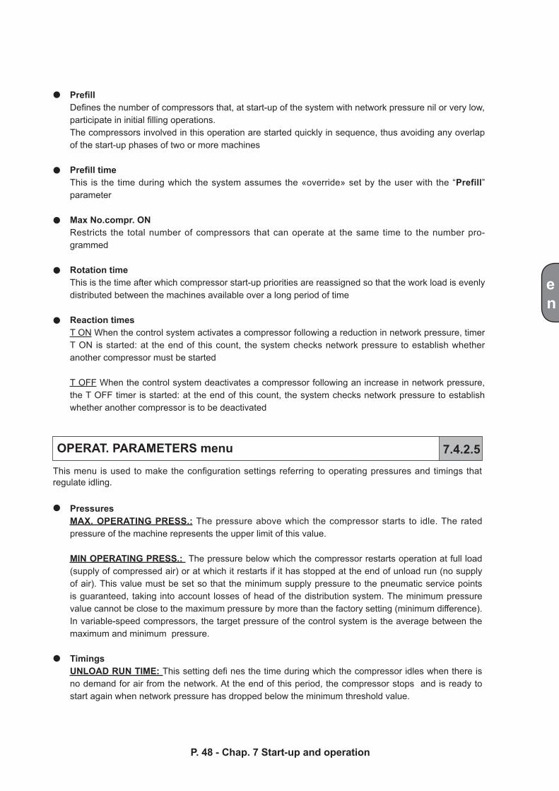
PrefillDefines the number of compressors that, at start-up of the system with network pressure nil or very low, participate in initial filling operations.The compressors involved in this operation are started quickly in sequence, thus avoiding any overlap of the start-up phases of two or more machines
Prefill timeThis is the time during which the system assumes the «override» set by the user with the “Prefill” parameter
Max No.compr. ONRestricts the total number of compressors that can operate at the same time to the number pro-grammed
Rotation timeThis is the time after which compressor start-up priorities are reassigned so that the work load is evenly distributed between the machines available over a long period of time
Reaction timesT ON When the control system activates a compressor following a reduction in network pressure, timer T ON is started: at the end of this count, the system checks network pressure to establish whether another compressor must be started
T OFF When the control system deactivates a compressor following an increase in network pressure, the T OFF timer is started: at the end of this count, the system checks network pressure to establish whether another compressor is to be deactivated
This menu is used to make the configuration settings referring to operating pressures and timings that regulate idling.
PressuresMAX. OPERATING PRESS.: The pressure above which the compressor starts to idle. The rated pressure of the machine represents the upper limit of this value.
MIN OPERATING PRESS.: The pressure below which the compressor restarts operation at full load (supply of compressed air) or at which it restarts if it has stopped at the end of unload run (no supply of air). This value must be set so that the minimum supply pressure to the pneumatic service points is guaranteed, taking into account losses of head of the distribution system. The minimum pressure value cannot be close to the maximum pressure by more than the factory setting (minimum difference).In variable-speed compressors, the target pressure of the control system is the average between the maximum and minimum pressure.
TimingsUNLOAD RUN TIME: This setting defi nes the time during which the compressor idles when there is no demand for air from the network. At the end of this period, the compressor stops and is ready to start again when network pressure has dropped below the minimum threshold value.
ESC
ESC
ESC
ESC
ESC
ESC
+ -
ESC+ -
+ -
+ -
+ -
ESC+ -
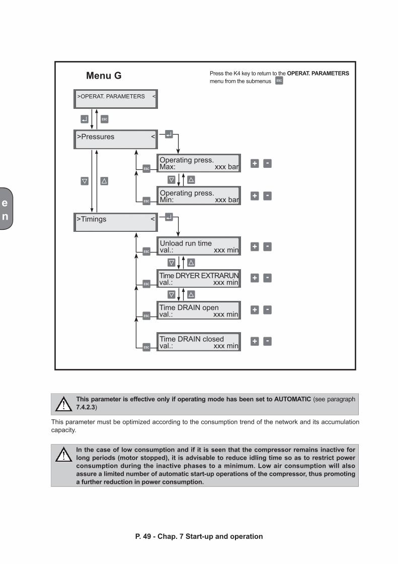
Menu G Press the K4 key to return to the OPERAT. PARAMETERS menu from the submenus
>OPERAT. PARAMETERS <
>Pressures <
>Timings <
Operating press. Max: xxx bar
Operating press.Min: xxx bar
Unload run time val.: xxx min
Time DRYER EXTRARUNval.: xxx min
Time DRAIN open val.: xxx min
Time DRAIN closedval.: xxx min
en
This parameter must be optimized according to the consumption trend of the network and its accumulation capacity.
This parameter is effective only if operating mode has been set to AUTOMATIC (see paragraph 7.4.2.3)
In the case of low consumption and if it is seen that the compressor remains inactive for long periods (motor stopped), it is advisable to reduce idling time so as to restrict power consumption during the inactive phases to a minimum. Low air consumption will also assure a limited number of automatic start-up operations of the compressor, thus promoting a further reduction in power consumption.
P. 49 - Chap. 7 Start-up and operation
en
PROGRAMMING menu 7.4.2.6
If air consumption is consistent and/or characterized by major variations, it is advisable to extend the idling time in order to “offset”, through the periods of idling, the various periods of operation at full load. This avoid stopping of the compressor with consequent delays in the supply of compressed air due to the start-up phases which are characterized by current take-off peaks tied to frequent starting.
The PROGRAMMING menu is used to set the schedule of compressor activities, defining the days and times when the compressor must be switched on. The compressor can be programmed on a daily basis (same for all the days) or on a weekly basis (a different program for each day of the week).
Reset programming:Makes it possible to cancel all the cycles set in both daily and weekly programming
Programming modeThis parameter informs the controller whether, once PROGRAM control has been activated (see paragraph 7.4.2.3), the machine must follow daily or weekly programming
Daily programmingDaily programming can be used to set up to four start/stop cycles. These cycles are repeated equally each day of the week.
The following rules apply:
The following rules apply:
Weekly programmingWeekly programming makes it possible to set different start/stop cycles for each day of the week, up to a maximum of three per day
Non-programmed cycles identified by the five hyphens that replace the time are not effective
Cycles for which the start and stop times coincide are not effective, similarly to those not program-med
If, in the last cycle programmed for a given day, the stopping time has been set to 24:00 and the first cycle programmed for the next day has been set to 00:00, the control unit will keep the compressor running during the change over at midnight from one day to the next
Non-programmed cycles identified by the five hyphens that replace the time are not effective
Cycles for which the start and stop times coincide are not effective, similarly to those not program-med
If, in the last cycle programmed, the stopping time has been set to 24:00 and the start time of the fi rst daily cycle has been set to 00:00, the control unit will keep the compressor running during the change over at midnight from one day to the next
P. 50 - Chap. 7 Start-up and operation
ESC
ESC
ESC
ESC
ESC
ESC
ESC
ESC
+ -
+ -
ESC
ESC
ESC
+ -
+ -
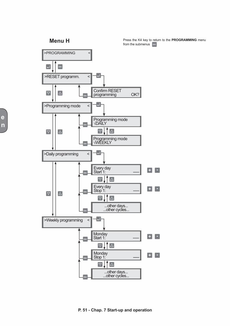
>RESET programm. <
>Programming mode <
>Daily programming <
>Weekly programming <
Confirm RESET programming OK?
Programming mode √DAILY
Programming mode√WEEKLY
Every day Start 1: -----
Every day Stop 1: -----
...other days......other cycles...
Monday Start 1: -----
Monday Stop 1: -----
...other days......other cycles...
>PROGRAMMING <
en
P. 51 - Chap. 7 Start-up and operation
Menu H Press the K4 key to return to the PROGRAMMING menu from the submenus
en
P. 52 - Chap. 7 Start-up and operation
NOTE: remember that control via keyboard of the control unit always has priority over any program control: this means that, if the program is to be effective, the K1-START button must be pressed setting the compressor to “Stand-by progr. con.”. Similarly, the compressor can be stopped without any risk of restart by the pre-set program pressing the K2-STOP key.
Therefore, to enable functioning with program control:1) Select PROGRAM control
2) Select the programming method to be used (DAILY/WEEKLY)
3) Program the daily or weekly schedule selected
4) Press the K1-START key on the control unit to enable program control
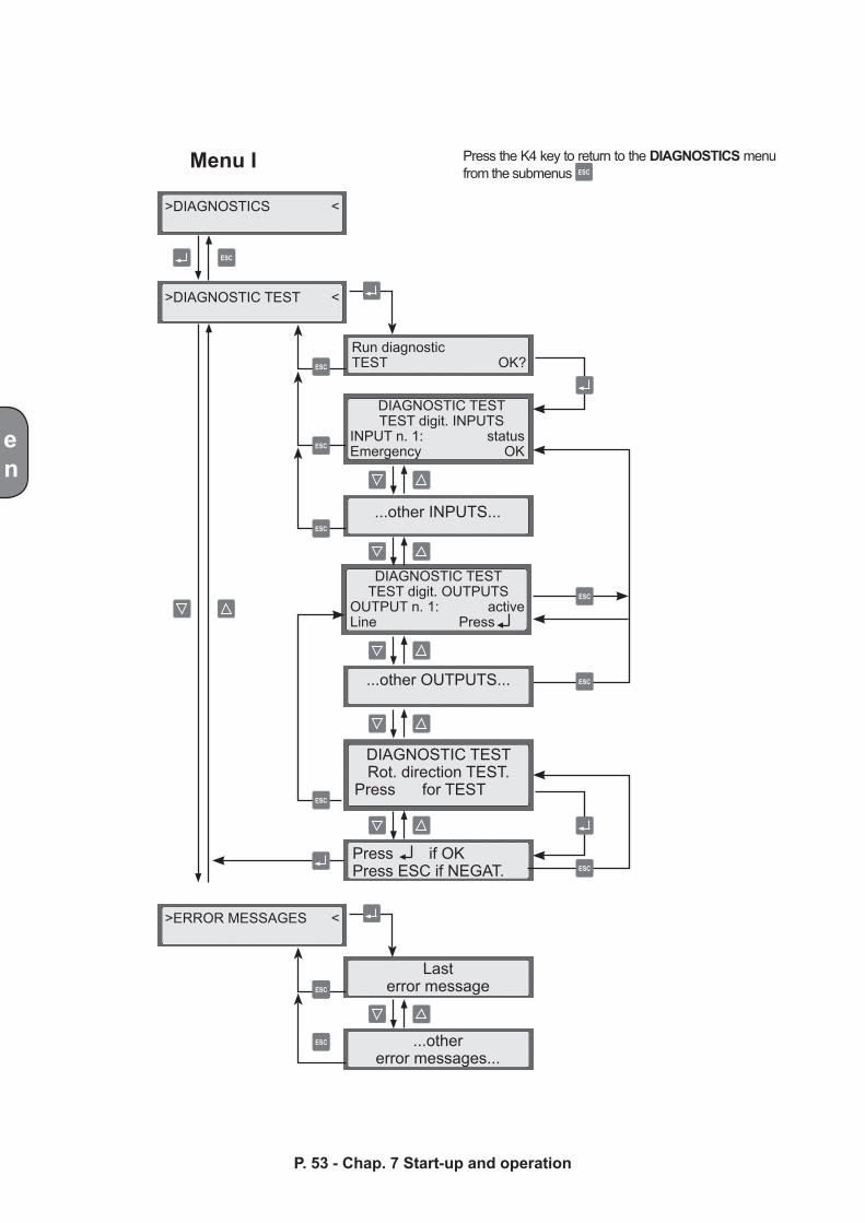
DIAGNOSTICS menu 7.4.2.7
From the diagnostics menu, it is possible to check functioning of the INPUTS, OUTPUTS and the direction of rotation of the compressor and fan. It is also possible to read the log of faults that have occurred on the compressor.
These diagnostic functions should be used only by expert personnel with in-depth knowledge of the compressor and how this operates.
Diagnostic TESTTo run the diagnostic TEST, comply with all the safety rules described in chapter 5
WARNING!!!When carrying out the test, certain parts of the machine are powered (control coils) and rotating parts are activated (motor, compressor, fan). The operator must therefore take all the necessary precautions during these checks.
Error messagesThe control unit saves all the faults that have occurred and which have caused stoppage of the machine (alarms). The following data are save for each error message:
- Type of error (alarm)
- Time, day, date on which the alarm occurred
- Total hours and hours of load run when the fault occurred
These indications are displayed cyclically on the third and fourth lines of the display
ESC
ESC
ESC
ESCESC
ESC
ESC
ESC
ESC
ESC
ESC
ESC
>DIAGNOSTICS <
>DIAGNOSTIC TEST <
Run diagnostic TEST OK?
DIAGNOSTIC TESTTEST digit. INPUTS
INPUT n. 1: statusEmergency OK
...other INPUTS...
DIAGNOSTIC TESTTEST digit. OUTPUTS
OUTPUT n. 1: activeLine Press
...other OUTPUTS...
DIAGNOSTIC TESTRot. direction TEST.
Press for TEST
>ERROR MESSAGES <
Press if OKPress ESC if NEGAT.
Lasterror message
...othererror messages...
en
P. 53 - Chap. 7 Start-up and operation
Menu I Press the K4 key to return to the DIAGNOSTICS menu from the submenus
ESC
ESC
ESC
ESC
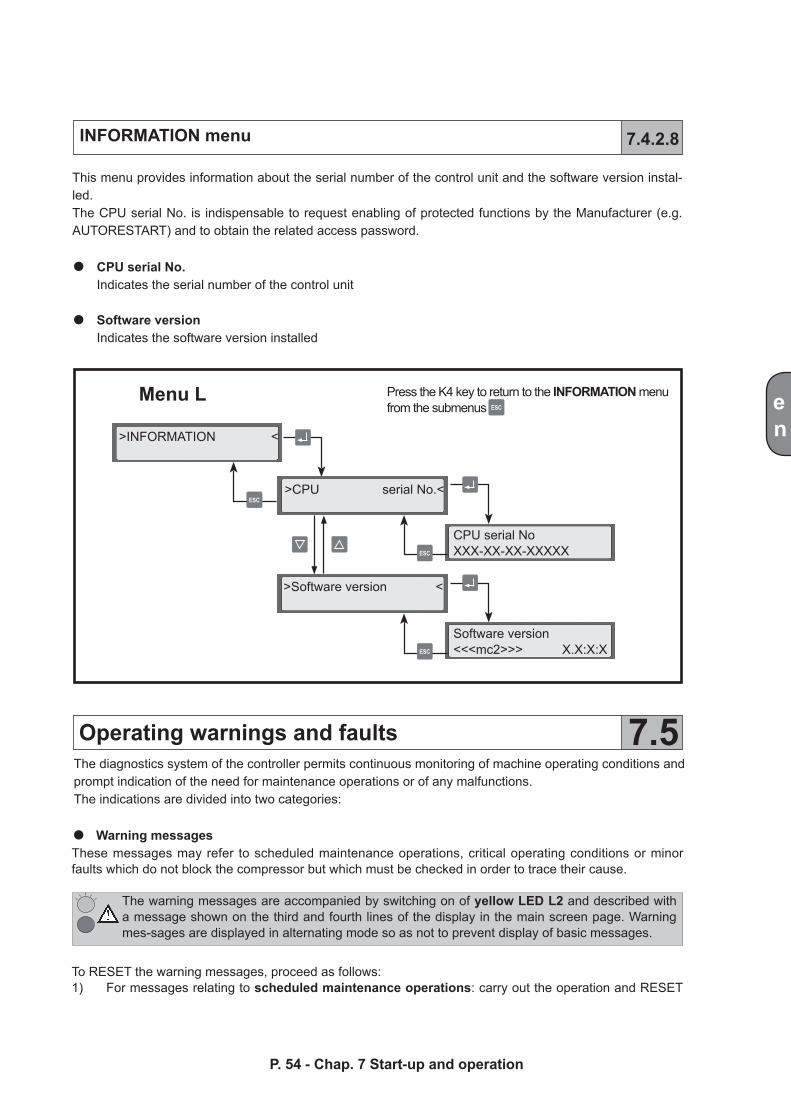
Menu L Press the K4 key to return to the INFORMATION menu from the submenus
>INFORMATION <
>CPU serial No.<
>Software version <
CPU serial NoXXX-XX-XX-XXXXX
Software version <<<mc2>>> X.X:X:X
en
P. 54 - Chap. 7 Start-up and operation
INFORMATION menu 7.4.2.8
This menu provides information about the serial number of the control unit and the software version instal-led.The CPU serial No. is indispensable to request enabling of protected functions by the Manufacturer (e.g. AUTORESTART) and to obtain the related access password.
CPU serial No.Indicates the serial number of the control unit
Software versionIndicates the software version installed
Operating warnings and faults 7.5The diagnostics system of the controller permits continuous monitoring of machine operating conditions and prompt indication of the need for maintenance operations or of any malfunctions.The indications are divided into two categories:
Warning messagesThese messages may refer to scheduled maintenance operations, critical operating conditions or minor faults which do not block the compressor but which must be checked in order to trace their cause.
The warning messages are accompanied by switching on of yellow LED L2 and described with a message shown on the third and fourth lines of the display in the main screen page. Warning mes-sages are displayed in alternating mode so as not to prevent display of basic messages.
To RESET the warning messages, proceed as follows:1) For messages relating to scheduled maintenance operations: carry out the operation and RESET
en
component life (see paragraph 7.4.2.2)Messages of this type are as follows:- Replace air filter- Replace oil filter- Replace oil- Replace separator filter
2) For critical operating condition messages: If possible eliminate the problem; the message will be cleared automatically
Messages of this type are as follows:- Compression temp. high- Ambient temperature low
WARNING!!!The machine can be configured so that if the warnings are not reset for a long period of time (e.g. failure to carry out programmed maintenance), the COMPRESSOR IS BLOCKED!!! Contact the Assistance Center or Customer Service of the Manufacturer immediately.Do not neglect maintenance request messages!
The following faults block the machine:- EMERGENCY STOP compress. - block- Compression temp. too high - block- Ambient temperature too low - block- Net pressure too high - block- Press Transducer error - block- Compr.temp. sensor error - block- Power supply phase sequence error - block- Short-cir. analog INPUT - block- Compress. motor overload - block- Fan overload - block- No. starts/hr too high - block
Alarm messagesThese messages indicate a serious fault that has blocked the compressor. The alarm may be due to a fault in the system or extremely critical operating conditions.
When a machine stoppage occurs, the compressor stops immediately, the red LED L3 of the alarms switches on and the message relating to the fault is displayed persistently in the main screen page. To RESET, first of all eliminate the fault: at this point, LED L3 starts to flash indicating that reset can be carried out pressing the RESET key.
All faults that cause blocking of the compressor are saved in an error message log file. To consult this log, refer to paragraph 7.4.2.7
P. 55 - Chap. 7 Start-up and operation
en
P. 56 - Chap. 7 Start-up and operation
- Power supply failure - block- Line voltage cutoff - block
Faults caused by failure to carry out maintenance must also be added to these: if the compressor is used for long periods without carrying out the scheduled maintenance indicated by the control unit, a machine blockage occurs accompanied by a message of the type:
Replace -------------- excess hrs - block
where the component to be replaced is displayed instead of the hyphens.
In this case, it is absolutely necessary to replace the component. If the compressor must be restarted, an emergency start-up procedure must be carried out. Contact the Service or Customer Centre of the Manufacturer immediately.
These additional alarm messages may be displayed in the case of variable-speed compressors:- INVERTER alarm - block- OverTemp. INVERTER - block- OverCurr. INVERTER - block- OverLoad INVERTER - block
To find out how to proceed in the case of an alarm, refer to chapter 9 “Troubleshooting”.
en
8 Compressorsin sequence
To establish communication between the control units, a communication module is required for each machine to be connected and the related connection cables.Therefore, contact your area dealer to purchase these.
The instructions for installation, programming and operation of the network of compressors are provided in the booklet furnished with the communication module.
The mc2 control unit includes all the control functions of the compressor on which it is directly installed.
For compressor rooms in which several machines equipped with this control unit are installed (up to a maximum of four units), a communication network can be set up between these for automatic, coordinated management of the compressors.
Communication between the compressors provides the following advantages:
constant pressure of the air supplied to pneumatic service points
energy saving:only the compressors necessary to supply the air required are activated
equal distribution of work load on the compressors available with consequent synchronization of scheduled maintenance operations
management of alarms and machine stoppages so as to prevent any interruption in the supply of compressed air
management of the network of compressors according to a program set by the user on a daily or weekly basis
P. 57 - Chap. 8 Compressors in sequence
en
9Troubleshooting
The machine does not start 9.1
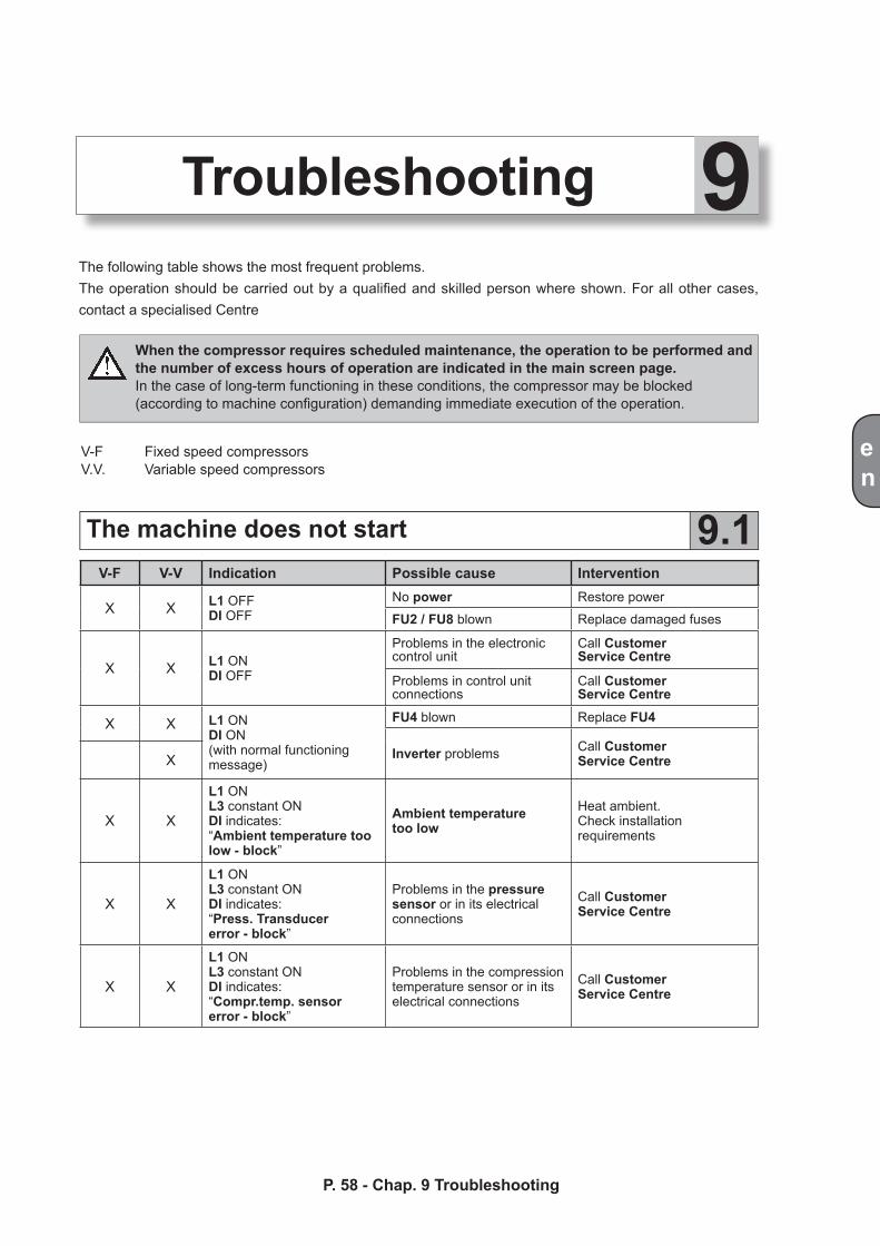
The following table shows the most frequent problems.The operation should be carried out by a qualified and skilled person where shown. For all other cases, contact a specialised Centre
When the compressor requires scheduled maintenance, the operation to be performed and the number of excess hours of operation are indicated in the main screen page.In the case of long-term functioning in these conditions, the compressor may be blocked (according to machine configuration) demanding immediate execution of the operation.
V-F Fixed speed compressorsV.V. Variable speed compressors
P. 58 - Chap. 9 Troubleshooting
V-F V-V Indication Possible cause Intervention
X X L1 OFFDI OFF
No power Restore power
FU2 / FU8 blown Replace damaged fuses
X X L1 ONDI OFF
Problems in the electronic control unit
Call Customer Service Centre
Problems in control unit connections
Call Customer Service Centre
X X L1 ONDI ON(with normal functioning message)
FU4 blown Replace FU4
Inverter problems Call Customer Service CentreX
X X
L1 ONL3 constant ONDI indicates:“Ambient temperature toolow - block”
Ambient temperaturetoo low
Heat ambient.Check installation requirements
X X
L1 ONL3 constant ONDI indicates:“Press. Transducererror - block”
Problems in the pressure sensor or in its electrical connections
Call Customer Service Centre
X X
L1 ONL3 constant ONDI indicates:“Compr.temp. sensorerror - block”
Problems in the compression temperature sensor or in its electrical connections
Call Customer Service Centre
en
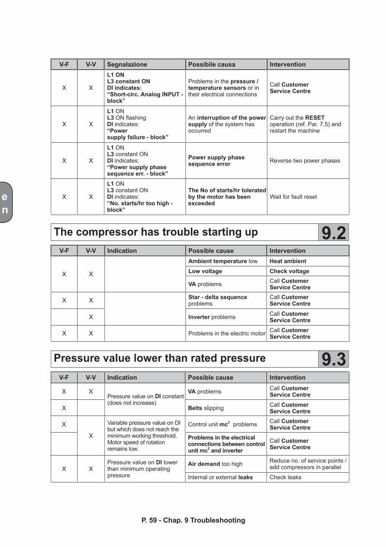
The compressor has trouble starting up
Pressure value lower than rated pressure
9.2
9.3
P. 59 - Chap. 9 Troubleshooting
V-F V-V Segnalazione Possibile causa Intervention
X X
L1 ONL3 constant ONDI indicates:“Short-circ. Analog INPUT - block”
Problems in the pressure / temperature sensors or intheir electrical connections
Call Customer Service Centre
X X
L1 ONL3 ON flashingDI indicates:“Powersupply failure - block”
An interruption of the power supply of the system has occurred
Carry out the RESET operation (ref. Par. 7.5) and restart the machine
X X
L1 ONL3 constant ONDI indicates:“Power supply phasesequence err. - block”
Power supply phase sequence error Reverse two power phases
X X
L1 ONL3 constant ONDI indicates:“No. starts/hr too high -block”
The No of starts/hr tolerated by the motor has been exceeded
Wait for fault reset
V-F V-V Indication Possible cause Intervention
X X
Ambient temperature low Heat ambientLow voltage Check voltage
VA problems Call Customer Service Centre
X X Star - delta sequenceproblems
Call Customer Service Centre
X Inverter problems Call Customer Service Centre
X X Problems in the electric motor Call Customer Service Centre
V-F V-V Indication Possible cause Intervention
X XPressure value on DI constant (does not increase)
VA problems Call Customer Service Centre
X Belts slipping Call Customer Service Centre
X
X
Variable pressure value on DI but which does not reach the minimum working threshold.Motor speed of rotation remains low.
Control unit mc2 problems Call Customer Service Centre
Problems in the electrical connections between control unit mc2 and inverter
Call Customer Service Centre
X XPressure value on DI lowerthan minimum operating pressure
Air demand too high Reduce no. of service points /add compressors in parallel
Internal or external leaks Check leaks
en
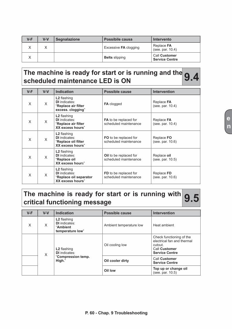
The machine is ready for start or is running and the scheduled maintenance LED is ON
The machine is ready for start or is running with critical functioning message
9.4
9.5
P. 60 - Chap. 9 TroubleshootingP. 59 - Chap. 9 Troubleshooting
V-F V-V Segnalazione Possibile causa Intervento
X X Excessive FA clogging Replace FA(see. par. 10.4)
X Belts slipping Call Customer Service Centre
V-F V-V Indication Possible cause Intervention
X XL2 flashingDI indicates:“Replace air filterexcess. clogging”
FA clogged Replace FA(see. par. 10.4)
X XL2 flashingDI indicates:“Replace air filterXX excess hours”
FA to be replaced for scheduled maintenance
Replace FA(see. par. 10.4)
X XL2 flashingDI indicates:“Replace oil filterXX excess hours”
FO to be replaced for scheduled maintenance
Replace FO(see. par. 10.6)
X XL2 flashingDI indicates:“Replace oilXX excess hours”
Oil to be replaced for scheduled maintenance
Replace oil(see. par. 10.5)
X XL2 flashingDI indicates:“Replace oil separatorXX excess hours”
FD to be replaced for scheduled maintenance
Replace FD(see. par. 10.6)
V-F V-V Indication Possible cause Intervention
X XL2 flashingDI indicates:“Ambient temperature low”
Ambient temperature low Heat ambient
XL2 flashingDI indicates:“Compression temp.High.”
Oil cooling low
Check functioning of the electrical fan and thermal cutout.Call Customer Service Centre
Oil cooler dirty Call Customer Service Centre
Oil low Top up or change oil(see. par. 10.5)
en
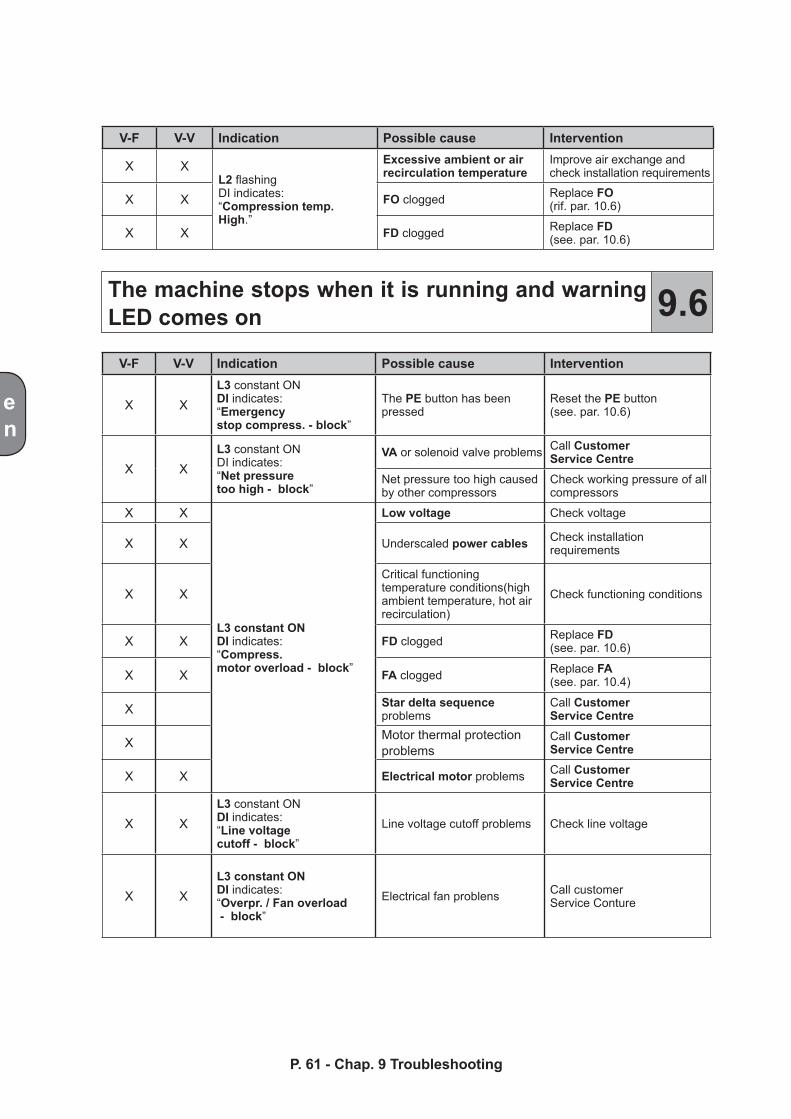
The machine stops when it is running and warning LED comes on 9.6
P. 61 - Chap. 9 Troubleshooting
V-F V-V Indication Possible cause Intervention
X XL2 flashingDI indicates:“Compression temp.High.”
Excessive ambient or air recirculation temperature
Improve air exchange and check installation requirements
X X FO clogged Replace FO(rif. par. 10.6)
X X FD clogged Replace FD(see. par. 10.6)
V-F V-V Indication Possible cause Intervention
X XL3 constant ONDI indicates:“Emergencystop compress. - block”
The PE button has been pressed
Reset the PE button(see. par. 10.6)
X XL3 constant ONDI indicates:“Net pressuretoo high - block”
VA or solenoid valve problems Call Customer Service Centre
Net pressure too high caused by other compressors
Check working pressure of all compressors
X X
L3 constant ONDI indicates:“Compress.motor overload - block”
Low voltage Check voltage
X X Underscaled power cables Check installation requirements
X XCritical functioning temperature conditions(high ambient temperature, hot air recirculation)
Check functioning conditions
X X FD clogged Replace FD(see. par. 10.6)
X X FA clogged Replace FA(see. par. 10.4)
X Star delta sequence problems
Call Customer Service Centre
X Motor thermal protectionproblems
Call Customer Service Centre
X X Electrical motor problems Call Customer Service Centre
X XL3 constant ONDI indicates:“Line voltagecutoff - block”
Line voltage cutoff problems Check line voltage
X XL3 constant ONDI indicates:“Overpr. / Fan overload - block”
Electrical fan problens Call customer Service Conture
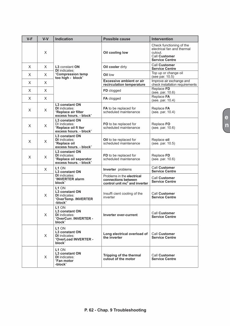
en
P. 62 - Chap. 9 TroubleshootingP. 61 - Chap. 9 Troubleshooting
V-F V-V Indication Possible cause Intervention
X
L3 constant ONDI indicates:“Compression temptoo high - block”
Oil cooling low
Check functioning of the electrical fan and thermal cutout.Call Customer Service Centre
X X Oil cooler dirty Call Customer Service Centre
X X Oil low Top up or change oil(see par. 10.5)
X X Excessive ambient or air recirculation temperature
Improve air exchange and check installation requirements
X X FD clogged Replace FD(see. par. 10.6)
X X FA clogged Replace FA(see. par. 10.4)
X XL3 constant ONDI indicates:“Replace air filterexcess hours. - block”
FA to be replaced for scheduled maintenance
Replace FA(see. par. 10.4)
X XL3 constant ONDI indicates:“Replace oil fi lterexcess hours. - block”
FO to be replaced for scheduled maintenance
Replace FO(see. par. 10.6)
X XL3 constant ONDI indicates:“Replace oilexcess hours. - block”
Oil to be replaced for scheduled maintenance
Replace oil(see. par. 10.5)
X XL3 constant ONDI indicates:“Replace oil separatorexcess hours. - block”
FD to be replaced for scheduled maintenance
Replace FD(see. par. 10.6)
X L1 ONL3 constant ONDI indicates:“INVERTER alarmblock”
Inverter problems Call Customer Service Centre
Problems in the electrical connections between control unit mc2 and inverter
Call Customer Service Centre
X
L1 ONL3 constant ONDI indicates:“OverTemp. INVERTER -block”
Insuffi cient cooling of the inverter
Call Customer Service Centre
X
L1 ONL3 constant ONDI indicates:“OverCurr. INVERTER -block”
Inverter over-current Call Customer Service Centre
X
L1 ONL3 constant ONDI indicates:“OverLoad INVERTER -block”
Long electrical overload of the inverter
Call Customer Service Centre
X
L1 ONL3 constant ONDI indicates:“Fan motor -block”
Tripping of the thermal cutout of the motor
Call Customer Service Centre
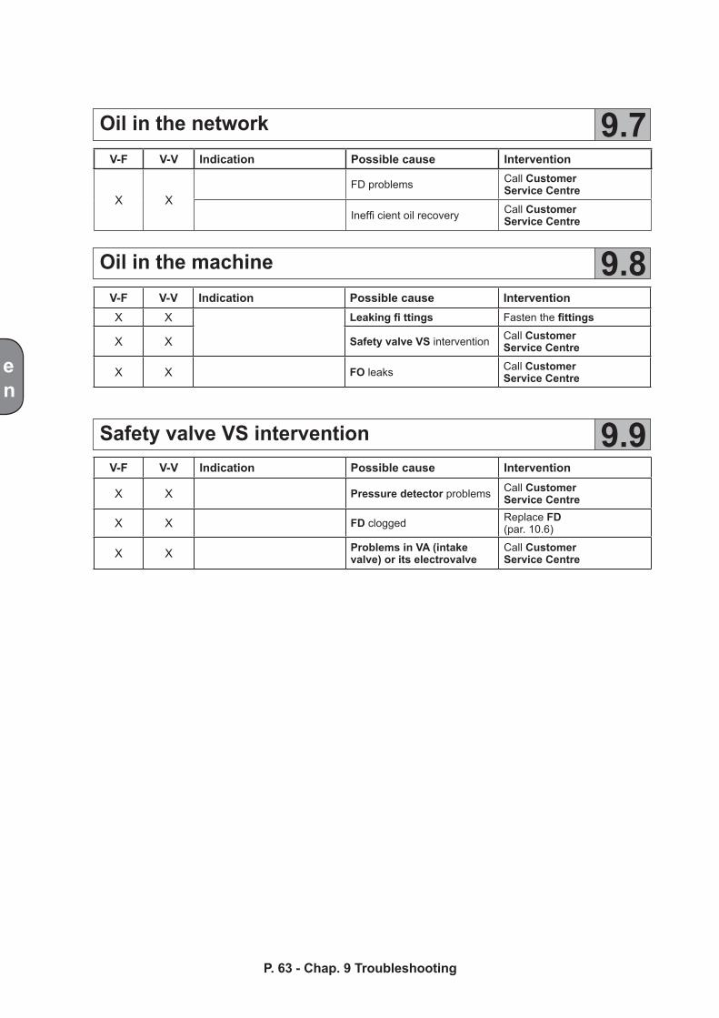
en
Oil in the network
Oil in the machine
Safety valve VS intervention
9.7
9.8
9.9
P. 63 - Chap. 9 Troubleshooting
V-F V-V Indication Possible cause Intervention
X X Pressure detector problems Call Customer Service Centre
X X FD clogged Replace FD(par. 10.6)
X X Problems in VA (intake valve) or its electrovalve
Call Customer Service Centre
V-F V-V Indication Possible cause InterventionX X Leaking fi ttings Fasten the fittings
X X Safety valve VS intervention Call Customer Service Centre
X X FO leaks Call Customer Service Centre
V-F V-V Indication Possible cause Intervention
X XFD problems Call Customer
Service Centre
Ineffi cient oil recovery Call Customer Service Centre
en
Operating cycle 10.1
10MaintenancePerform the scheduled maintenance operations to maintain compressor performance.
Various routine maintenance operation can be carried out by user provided they are carried out by skilled personnel. If routine maintenance is provided by a Service Centre and the related confi guration has been pro-duced, the user cannot RESET the components even if these have been replaced by the user (see paragraph 7.4.2.2)
Use only original spare parts
Instructions are provided in the following paragraphs.
Before performing any maintenance operations read the operator safety precautions in chapter 5 carefully. These precautions must be followed scrupulously for all maintenance operations
The compressor unit consists of two rotors (male and female) with special asymmetrical profile, mounted on rolling bearings, The male rotor drives and the female rotor is driven. The two rotors are not indirect contact thanks to a thin film of oil which protects the coupled surfaces.The oil serves various purposes. It lubricates the bearings and the rotors, eliminates the heat produced by the compressed air, it creates an “airtight fluid seal” and reduces hazardous gaps in the air-end unit.In fixed speed compressors, starting is of the delta-star type. During the star phase, intake valve VA is closed, thus permitting no-load start-up with less effort and lower energy consumption.After a preset time of a few seconds, the PC control unit invokes changeover to the delta connection; with a short transient phase, the MP motor reaches rated rotation speed. The intake valve opens thus starting the normal work cycle.In variable speed compressors, the start-up phase takes place with acceleration of the electrical motor which, powered by the inverter, is brought to maximum speed of rotation compatible with network pressure.As soon as this is permitted by rotation speed, the intake valve VA opens and the machine work cycle begins.The air is drawn through the filter FA, passes into the air-end unit where it is mixed with the oil injected. The air is gradually compressed and pushed into the separator receiver where initial oil separation occurs by gravity.The air, which is still mixed with oil droplets, follows the shape of the receiver and passes through the FD oil separator. Due to the effect of coalescence, the droplets of oil merge and are deposited on the bottom of the filter from where they are routed towards the air-end unit by means of a pipe.The purified air passes through the check and minimum pressure valve VR which opens only when a threshold of approximately 4 bar is exceeded. This ensures correct system lubrication in all operating conditions.The oil deposited on the bottom of receiver SS is conveyed under pressure to the oil cooler RO where it is cooled. Oil temperature is electronically managed by the control panel PC; the oil passes into filter FO and returns to the air end.Temperature sensor STO inserted in the air end and connected to the microprocessor permits constantmonitoring of the temperature inside the air-end unit.
P. 64 - Chap. 10 MaintenanceP. 63 - Chap. 9 Troubleshooting
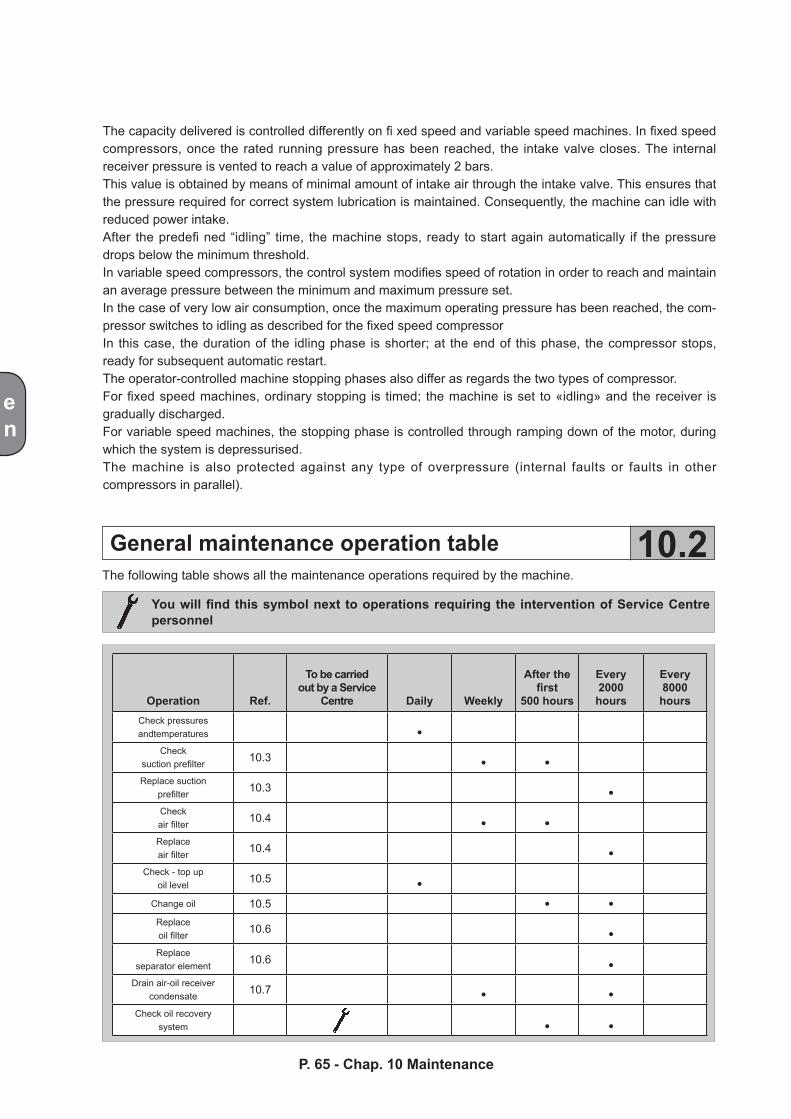
Operation Ref.
To be carriedout by a Service
Centre Daily Weekly
After thefirst
500 hours
Every2000hours
Every8000hours
Check pressures andtemperatures •
Checksuction prefilter 10.3 • •Replace suction
prefilter 10.3 •Checkair filter 10.4 • •Replaceair filter 10.4 •
Check - top upoil level 10.5 •
Change oil 10.5 • •Replaceoil filter 10.6 •Replace
separator element 10.6 •Drain air-oil receiver
condensate 10.7 • •Check oil recovery
system • •
en
General maintenance operation table 10.2
The capacity delivered is controlled differently on fi xed speed and variable speed machines. In fixed speed compressors, once the rated running pressure has been reached, the intake valve closes. The internal receiver pressure is vented to reach a value of approximately 2 bars.This value is obtained by means of minimal amount of intake air through the intake valve. This ensures that the pressure required for correct system lubrication is maintained. Consequently, the machine can idle with reduced power intake.After the predefi ned “idling” time, the machine stops, ready to start again automatically if the pressure drops below the minimum threshold.In variable speed compressors, the control system modifies speed of rotation in order to reach and maintain an average pressure between the minimum and maximum pressure set.In the case of very low air consumption, once the maximum operating pressure has been reached, the com-pressor switches to idling as described for the fixed speed compressorIn this case, the duration of the idling phase is shorter; at the end of this phase, the compressor stops, ready for subsequent automatic restart.The operator-controlled machine stopping phases also differ as regards the two types of compressor.For fixed speed machines, ordinary stopping is timed; the machine is set to «idling» and the receiver is gradually discharged.For variable speed machines, the stopping phase is controlled through ramping down of the motor, during which the system is depressurised.The machine is also protected against any type of overpressure (internal faults or faults in other compressors in parallel).
The following table shows all the maintenance operations required by the machine.
You will find this symbol next to operations requiring the intervention of Service Centre personnel
P. 65 - Chap. 10 Maintenance
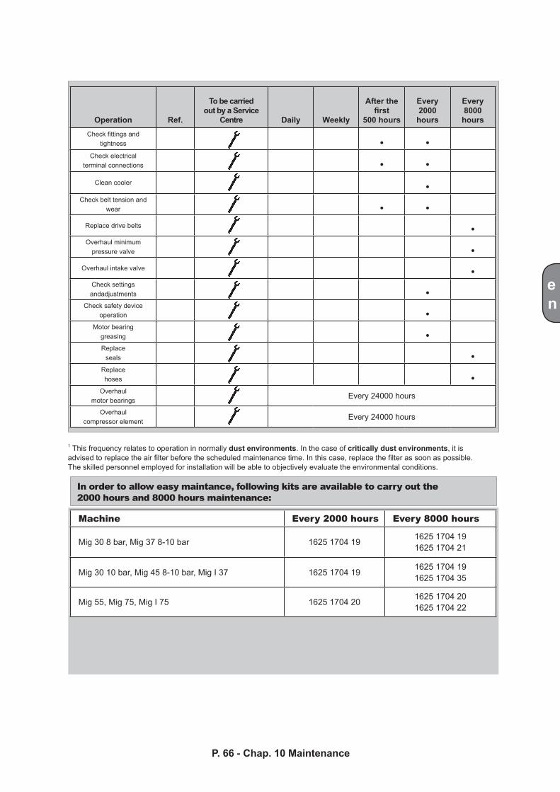
Operation Ref.
To be carriedout by a Service
Centre Daily Weekly
After thefirst
500 hours
Every2000hours
Every8000hours
Check fittings andtightness • •
Check electricalterminal connections • •
Clean cooler •Check belt tension and
wear • •Replace drive belts •Overhaul minimum
pressure valve •Overhaul intake valve •
Check settings andadjustments •
Check safety device operation •
Motor bearinggreasing •Replace
seals •Replacehoses •
Overhaulmotor bearings Every 24000 hours
Overhaulcompressor element Every 24000 hours
Machine Every 2000 hours Every 8000 hours
Mig 30 8 bar, Mig 37 8-10 bar 1625 1704 191625 1704 191625 1704 21
Mig 30 10 bar, Mig 45 8-10 bar, Mig I 37 1625 1704 191625 1704 191625 1704 35
Mig 55, Mig 75, Mig I 75 1625 1704 201625 1704 201625 1704 22
en
P. 66 - Chap. 10 MaintenanceP. 65 - Chap. 10 Maintenance
1 This frequency relates to operation in normally dust environments. In the case of critically dust environments, it is advised to replace the air filter before the scheduled maintenance time. In this case, replace the filter as soon as possible. The skilled personnel employed for installation will be able to objectively evaluate the environmental conditions.
In order to allow easy maintance, following kits are available to carry out the 2000 hours and 8000 hours maintenance:
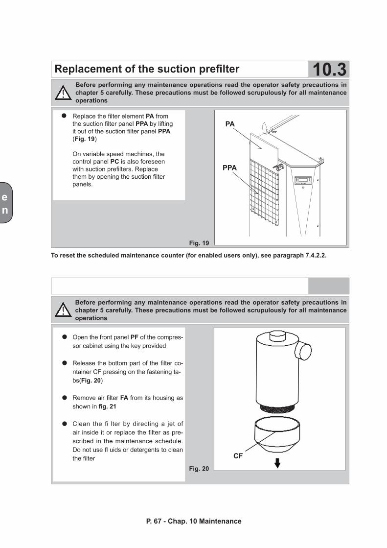
PA
PPA
CF
en
Replacement of the suction prefilter 10.3
Open the front panel PF of the compres-sor cabinet using the key provided
Release the bottom part of the filter co-ntainer CF pressing on the fastening ta-bs(Fig. 20)
Remove air filter FA from its housing as shown in fig. 21
Clean the fi lter by directing a jet of air inside it or replace the filter as pre-scribed in the maintenance schedule. Do not use fl uids or detergents to clean the filter
Fig. 19
Fig. 20
Before performing any maintenance operations read the operator safety precautions in chapter 5 carefully. These precautions must be followed scrupulously for all maintenance operations
Replace the filter element PA from the suction filter panel PPA by lifting it out of the suction filter panel PPA (Fig. 19)
On variable speed machines, the control panel PC is also foreseen with suction prefilters. Replace them by opening the suction filter panels.
To reset the scheduled maintenance counter (for enabled users only), see paragraph 7.4.2.2.
Before performing any maintenance operations read the operator safety precautions in chapter 5 carefully. These precautions must be followed scrupulously for all maintenance operations
P. 67 - Chap. 10 Maintenance
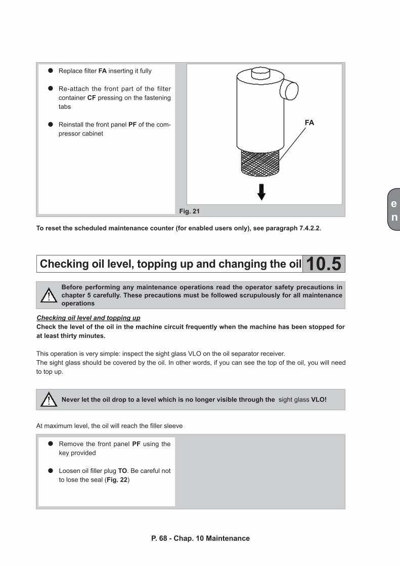
FA
en
Checking oil level, topping up and changing the oil 10.5
Fig. 21
P. 68 - Chap. 10 MaintenanceP. 67 - Chap. 10 Maintenance
Replace filter FA inserting it fully
Re-attach the front part of the filter container CF pressing on the fastening tabs
Reinstall the front panel PF of the com-pressor cabinet
To reset the scheduled maintenance counter (for enabled users only), see paragraph 7.4.2.2.
Before performing any maintenance operations read the operator safety precautions in chapter 5 carefully. These precautions must be followed scrupulously for all maintenance operations
Checking oil level and topping upCheck the level of the oil in the machine circuit frequently when the machine has been stopped for at least thirty minutes.
This operation is very simple: inspect the sight glass VLO on the oil separator receiver.The sight glass should be covered by the oil. In other words, if you can see the top of the oil, you will need to top up.
Never let the oil drop to a level which is no longer visible through the sight glass VLO!
At maximum level, the oil will reach the filler sleeve
Remove the front panel PF using the key provided Loosen oil filler plug TO. Be careful not to lose the seal (Fig. 22)
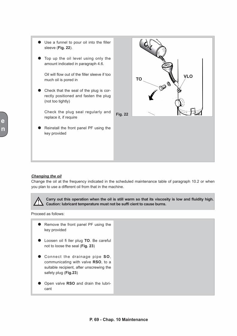
en
TO VLO
Fig. 22
P. 69 - Chap. 10 Maintenance
Use a funnel to pour oil into the filler sleeve (Fig. 22).
Top up the oil level using only the amount indicated in paragraph 4.6.
Oil will flow out of the filler sleeve if too much oil is pored in
Check that the seal of the plug is cor-rectly positioned and fasten the plug (not too tightly)
Check the plug seal regularly and replace it, if require
Reinstall the front panel PF using the key provided
Changing the oilChange the oil at the frequency indicated in the scheduled maintenance table of paragraph 10.2 or when you plan to use a different oil from that in the machine.
Carry out this operation when the oil is still warm so that its viscosity is low and fluidity high. Caution: lubricant temperature must not be suffi cient to cause burns.
Proceed as follows:
Remove the front panel PF using the key provided
Loosen oil fi ller plug TO. Be careful not to loose the seal (Fig. 23)
Connect the dra inage p ipe SO , communicating with valve RSO, to a suitable recipient, after unscrewing the safety plug (Fig.23)
Open valve RSO and drain the lubri-cant
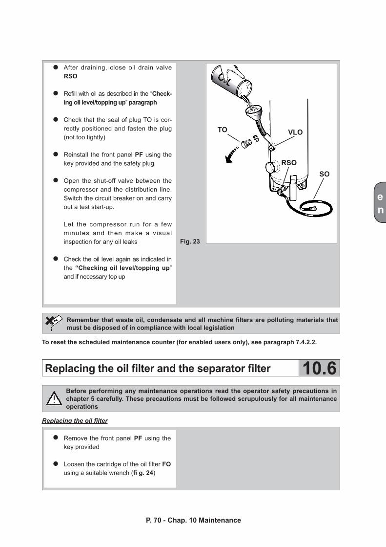
TO VLO
RSOSO
en
Fig. 23
P. 70 - Chap. 10 MaintenanceP. 69 - Chap. 10 Maintenance
Replacing the oil filter and the separator filter 10.6
After draining, close oil drain valve RSO
Refill with oil as described in the “Check-ing oil level/topping up” paragraph
Check that the seal of plug TO is cor-rectly positioned and fasten the plug (not too tightly)
Reinstall the front panel PF using the key provided and the safety plug
Open the shut-off valve between the compressor and the distribution line. Switch the circuit breaker on and carry out a test start-up.
Let the compressor run for a few minutes and then make a visual inspection for any oil leaks
Check the oil level again as indicated in the “Checking oil level/topping up” and if necessary top up
Remember that waste oil, condensate and all machine filters are polluting materials that must be disposed of in compliance with local legislation
To reset the scheduled maintenance counter (for enabled users only), see paragraph 7.4.2.2.
Before performing any maintenance operations read the operator safety precautions in chapter 5 carefully. These precautions must be followed scrupulously for all maintenance operations
Replacing the oil filter
Remove the front panel PF using the key provided
Loosen the cartridge of the oil filter FO using a suitable wrench (fi g. 24)
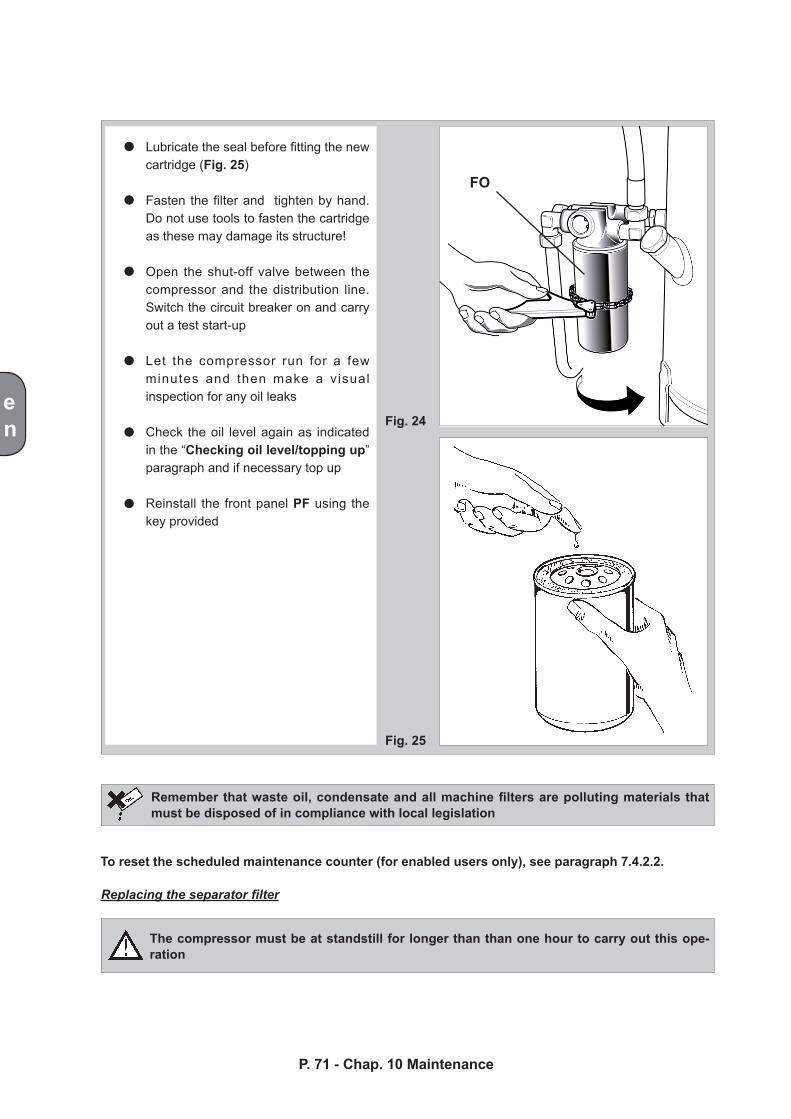
FO
en
P. 71 - Chap. 10 Maintenance
Fig. 24
Fig. 25
Lubricate the seal before fitting the new cartridge (Fig. 25)
Fasten the filter and tighten by hand. Do not use tools to fasten the cartridge as these may damage its structure!
Open the shut-off valve between the compressor and the distribution line. Switch the circuit breaker on and carry out a test start-up
Let the compressor run for a few minutes and then make a visual inspection for any oil leaks
Check the oil level again as indicated in the “Checking oil level/topping up” paragraph and if necessary top up
Reinstall the front panel PF using the key provided
Remember that waste oil, condensate and all machine filters are polluting materials that must be disposed of in compliance with local legislation
To reset the scheduled maintenance counter (for enabled users only), see paragraph 7.4.2.2.
Replacing the separator filter
The compressor must be at standstill for longer than than one hour to carry out this ope-ration
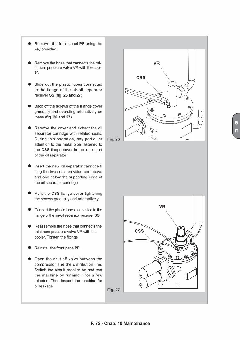
CSS
CSS
VR
VR
en
P. 72 - Chap. 10 MaintenanceP. 71 - Chap. 10 Maintenance
Fig. 26
Fig. 27
Remove the front panel PF using the key provided.
Remove the hose that cannects the mi-nimum pressure valve VR with the coo-er.
Slide out the plastic tubes connected to the flange of the air-oil separator receiver SS (fig. 26 and 27)
Back off the screws of the fl ange cover gradually and operating artenatively on these (fig. 26 and 27)
Remove the cover and extract the oil separator cartridge with related seals. During this operation, pay particular attention to the metal pipe fastened to the CSS flange cover in the inner part of the oil separator
Insert the new oil separator cartridge fi tting the two seals provided one above and one below the supporting edge of the oil separator cartridge
Refit the CSS flange cover tightening the screws gradually and arternatively
Connect the plastic tunes connected to the flange of the air-oil separator receiver SS
Reassemble the hose that connects theminimum pressure valve VR with the cooler. Tighten the fittings
Reinstall the front panelPF.
Open the shut-off valve between the compressor and the distribution line. Switch the circuit breaker on and test the machine by running it for a few minutes. Then inspect the machine for oil leakage
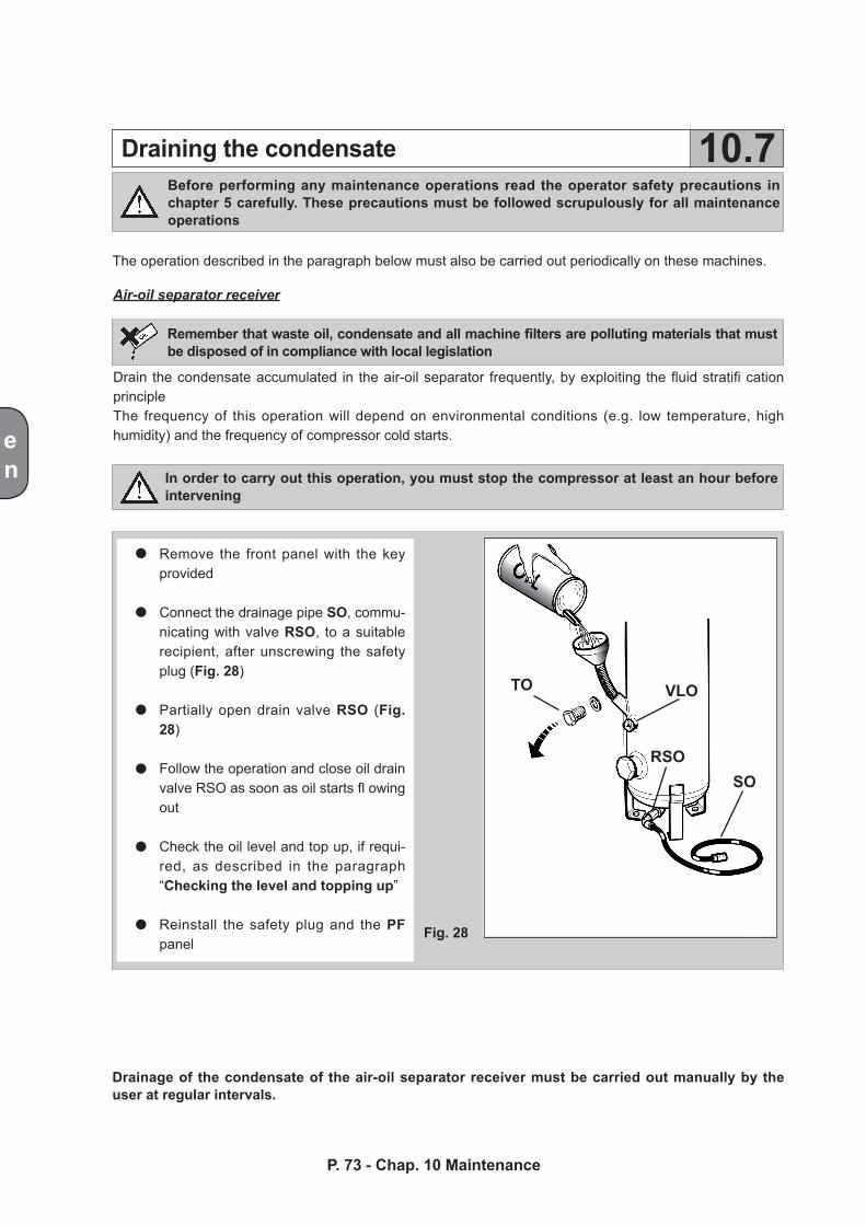
TO
SORSO
VLO
en
P. 73 - Chap. 10 Maintenance
Draining the condensate 10.7Before performing any maintenance operations read the operator safety precautions in chapter 5 carefully. These precautions must be followed scrupulously for all maintenance operations
The operation described in the paragraph below must also be carried out periodically on these machines.
Air-oil separator receiver
Remember that waste oil, condensate and all machine filters are polluting materials that must be disposed of in compliance with local legislation
Drain the condensate accumulated in the air-oil separator frequently, by exploiting the fluid stratifi cation principleThe frequency of this operation will depend on environmental conditions (e.g. low temperature, high humidity) and the frequency of compressor cold starts.
In order to carry out this operation, you must stop the compressor at least an hour before intervening
Fig. 28
Drainage of the condensate of the air-oil separator receiver must be carried out manually by the user at regular intervals.
Remove the front panel with the key provided
Connect the drainage pipe SO, commu-nicating with valve RSO, to a suitable recipient, after unscrewing the safety plug (Fig. 28)
Partially open drain valve RSO (Fig. 28)
Follow the operation and close oil drain valve RSO as soon as oil starts fl owing out
Check the oil level and top up, if requi-red, as described in the paragraph “Checking the level and topping up”
Reinstall the safety plug and the PF panel
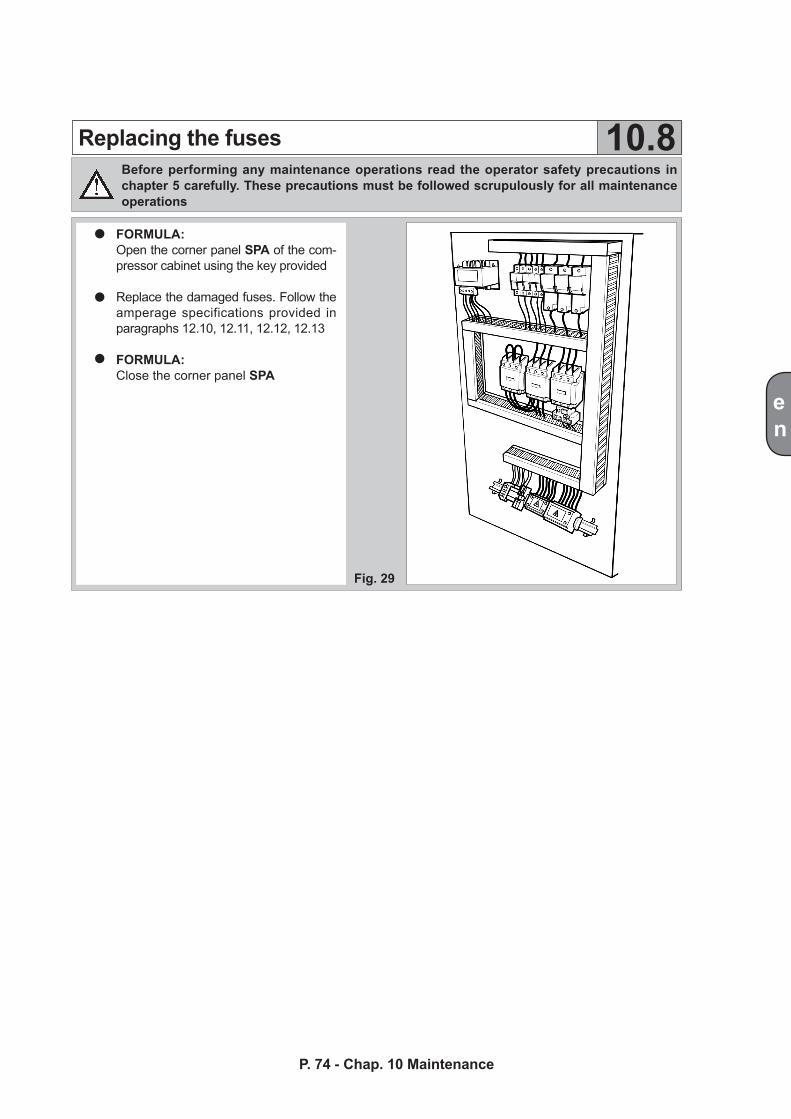
en
P. 74 - Chap. 10 MaintenanceP. 73 - Chap. 10 Maintenance
Replacing the fuses 10.8
Fig. 29
Before performing any maintenance operations read the operator safety precautions in chapter 5 carefully. These precautions must be followed scrupulously for all maintenance operations
FORMULA:Open the corner panel SPA of the com-pressor cabinet using the key provided
Replace the damaged fuses. Follow the amperage specifications provided in paragraphs 12.10, 12.11, 12.12, 12.13
FORMULA: Close the corner panel SPA
en
11 Spare Parts andService Centres
The Manufacturer provides an efficient after-sales service through a large service network and a Technical Department for solving any problems.Always specify the compressor model and serial number when communicating with Authorized Service Centres and the Manufacturer.
The codes of the most commonly used spares are included in the specific list on board the machine For other spares, contact the authorized assistance centers.
P. 75 - Chap. 11 Spare parts and Service Centres
Spare parts and consumable material codes 11.1
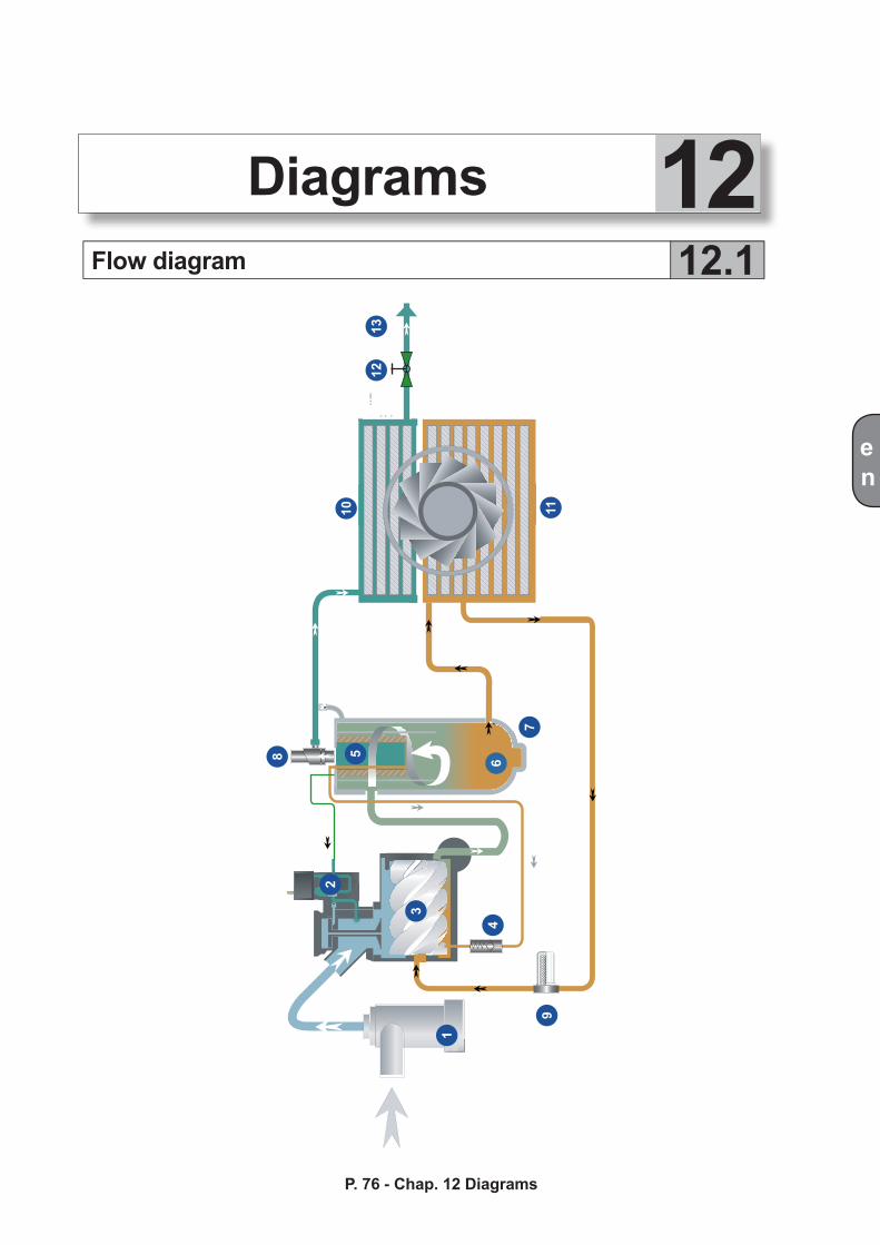
1
3
2
8 5
7
6
10 11
1213
9
4
en
Flow diagram 12.1
P. 76 - Chap. 12 DiagramsP. 75 - Chap. 11 Spare parts and Service Centres
12Diagrams
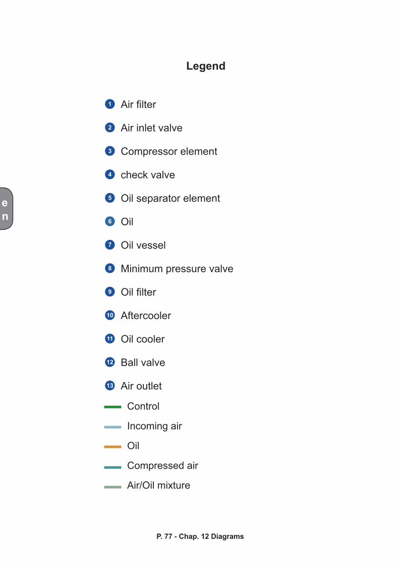
1
2
3
4
5
6
7
8
9
10
11
12
13
en
P. 77 - Chap. 12 Diagrams
Legend
Air filter
Air inlet valve
Compressor element
check valve
Oil separator element
Oil
Oil vessel
Minimum pressure valve
Oil filter
Aftercooler
Oil cooler
Ball valve
Air outlet
Control
Incoming air
Oil
Compressed air
Air/Oil mixture
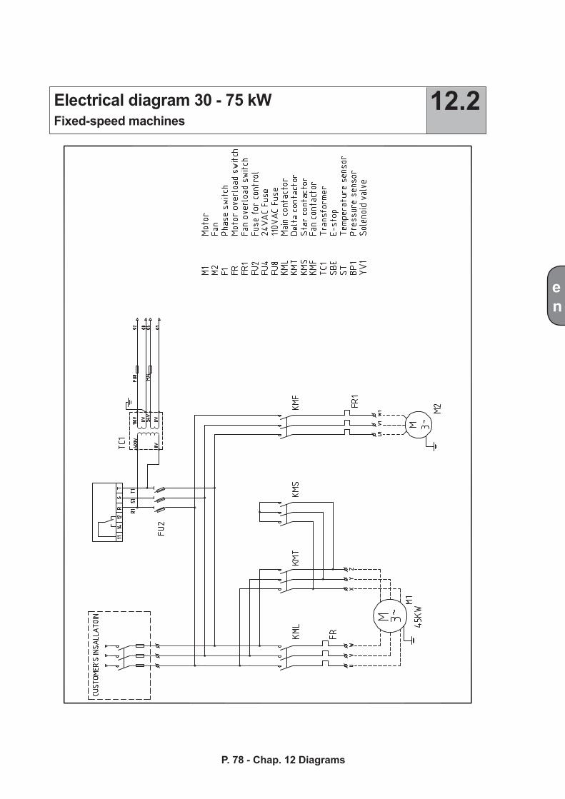
en
P. 78 - Chap. 12 DiagramsP. 77 - Chap. 12 Diagrams
Electrical diagram 30 - 75 kWFixed-speed machines
12.2
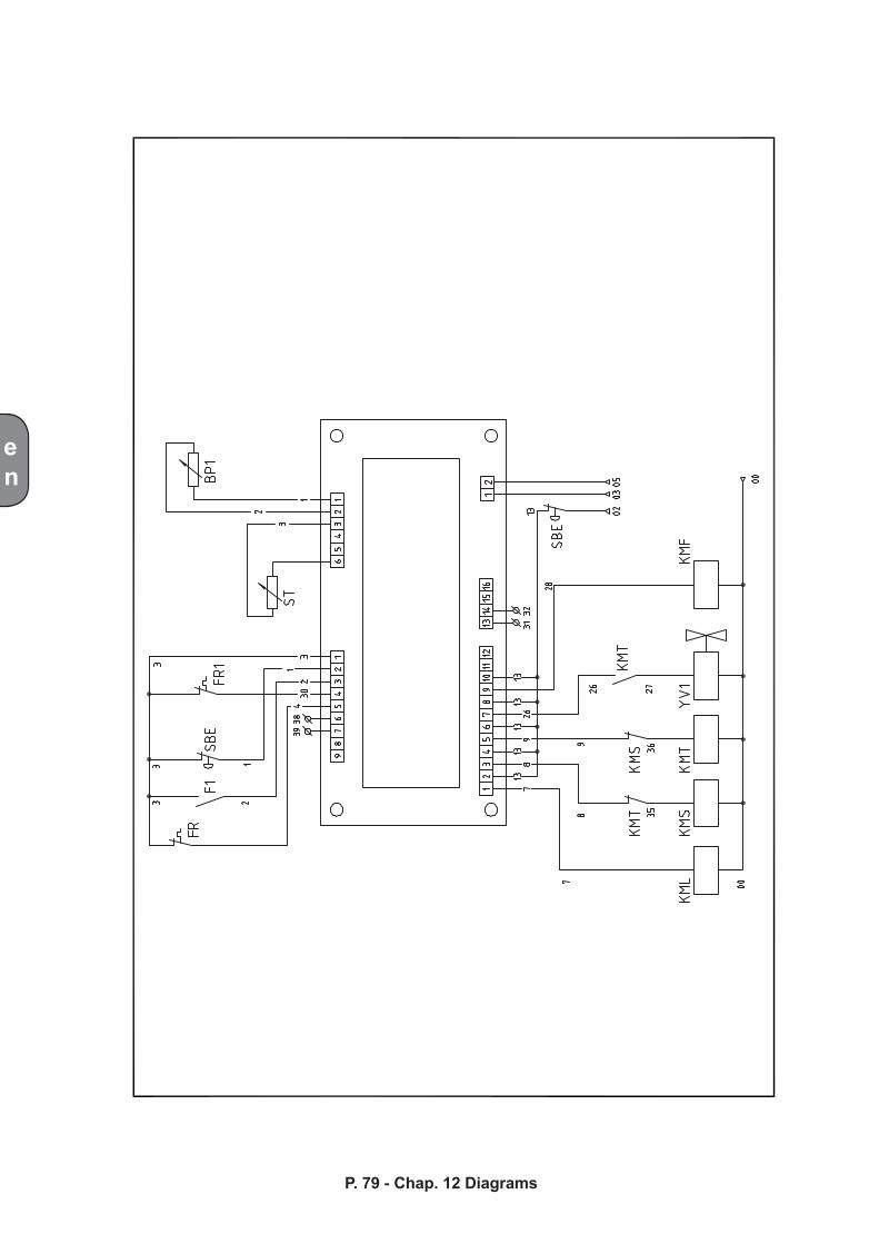
en
P. 79 - Chap. 12 Diagrams
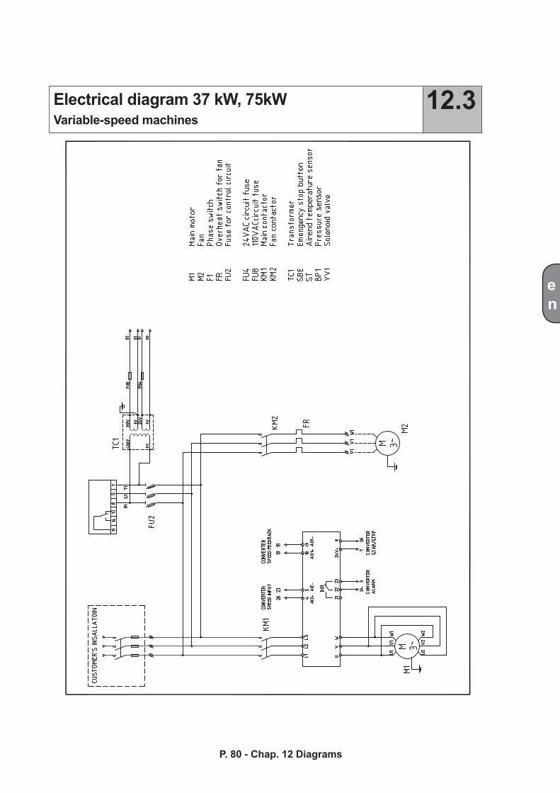
en
P. 80 - Chap. 12 DiagramsP. 79 - Chap. 12 Diagrams
Electrical diagram 37 kW, 75kWVariable-speed machines
12.3
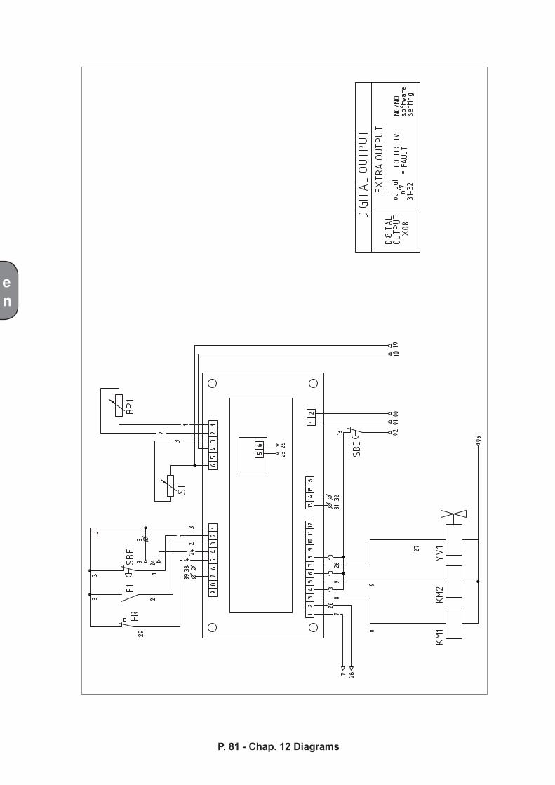
en
P. 81 - Chap. 12 Diagrams
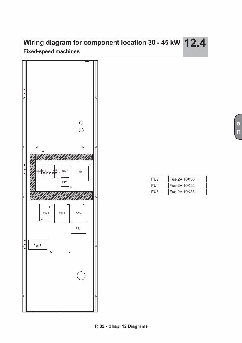
en
P. 82 - Chap. 12 DiagramsP. 81 - Chap. 12 Diagrams
Wiring diagram for component location 30 - 45 kWFixed-speed machines
12.4
FU2 Fus-2A 10X38FU4 Fus-2A 10X38FU8 Fus-2A 10X38
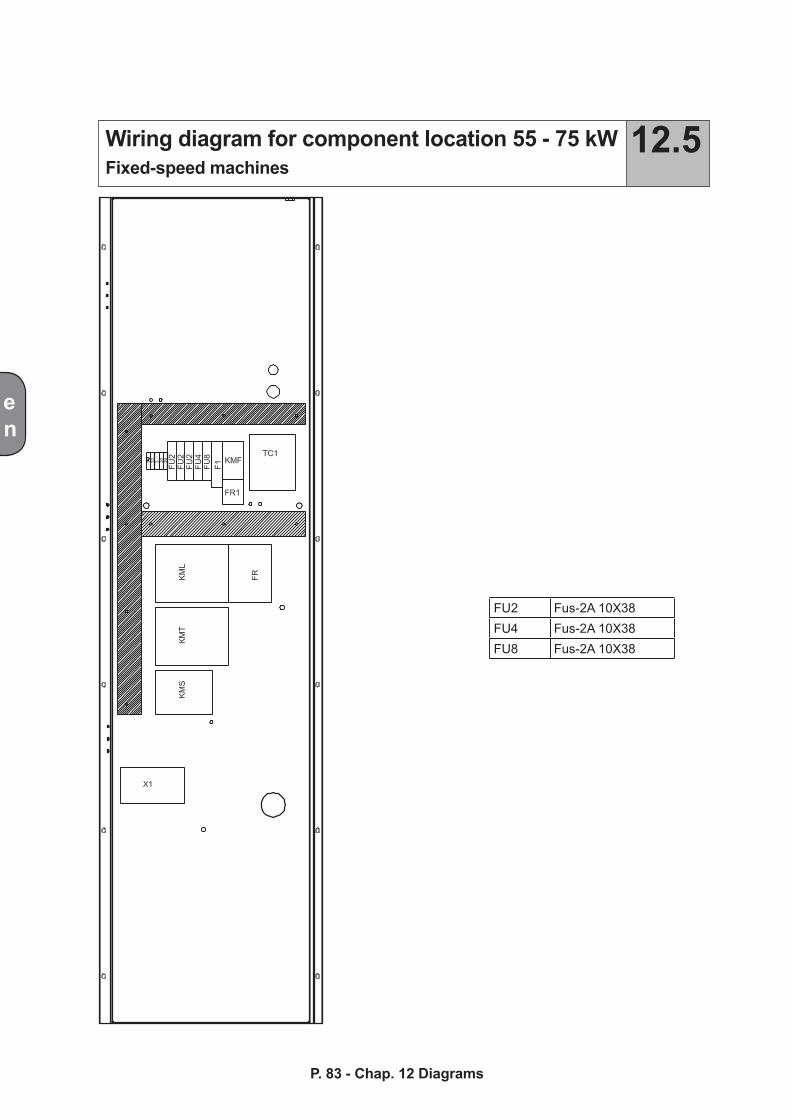
en
P. 83 - Chap. 12 Diagrams
Wiring diagram for component location 55 - 75 kWFixed-speed machines
12.5
FU2 Fus-2A 10X38FU4 Fus-2A 10X38FU8 Fus-2A 10X38
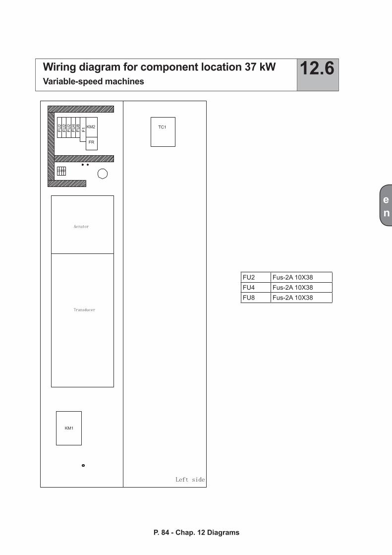
en
P. 84 - Chap. 12 DiagramsP. 83 - Chap. 12 Diagrams
Wiring diagram for component location 37 kWVariable-speed machines
12.6
FU2 Fus-2A 10X38FU4 Fus-2A 10X38FU8 Fus-2A 10X38
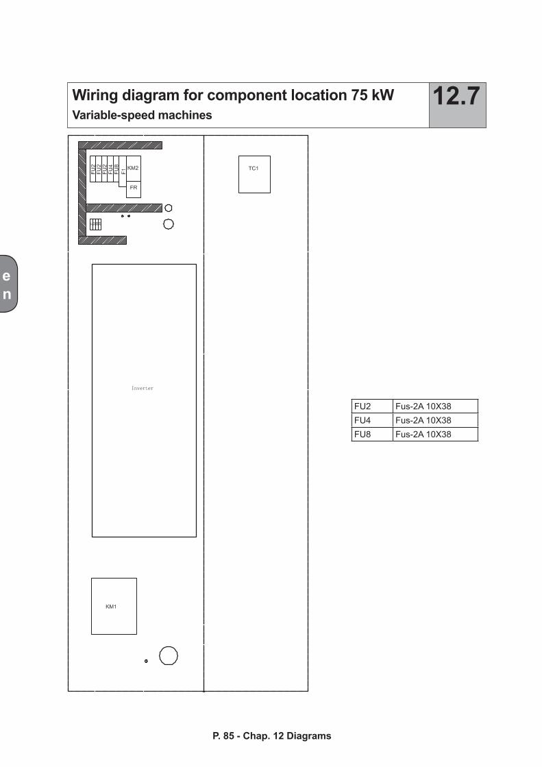
en
P. 85 - Chap. 12 Diagrams
Wiring diagram for component location 75 kWVariable-speed machines
12.7
FU2 Fus-2A 10X38FU4 Fus-2A 10X38FU8 Fus-2A 10X38