Embed Size (px)
Citation preview
Cleveland State University Cleveland State University
EngagedScholarship@CSU EngagedScholarship@CSU
Physics Faculty Publications Physics Department
6-1-2011
Mie Scattering in the Time Domain. Part I. The Role of Surface Mie Scattering in the Time Domain. Part I. The Role of Surface
Waves Waves
James A. Lock Cleveland State University, [email protected]
Philip Laven
Follow this and additional works at: https://engagedscholarship.csuohio.edu/sciphysics_facpub
Part of the Physics Commons
How does access to this work benefit you? Let us know! How does access to this work benefit you? Let us know!
Publisher's Statement This paper was published in Journal of the Optical Society of America A: Optics Image Science
and Vision and is made available as an electronic reprint with the permission of OSA. The paper
can be found at the following URL on the OSA website: http://www.opticsinfobase.org/josaa/
abstract.cfm?URI=josaa-28-6-1086. Systematic or multiple reproduction or distribution to
multiple locations via electronic or other means is prohibited and is subject to penalties under
law.
Original Citation Original Citation Lock, James A. and Philip Laven. "Mie Scattering in the Time Domain. Part I. The Role of Surface Waves." Journal of the Optical Society of America A: Optics Image Science and Vision 28 (2011): 1086-1095.
Repository Citation Lock, James A. and Laven, Philip, "Mie Scattering in the Time Domain. Part I. The Role of Surface Waves" (2011). Physics Faculty Publications. 63. https://engagedscholarship.csuohio.edu/sciphysics_facpub/63
This Article is brought to you for free and open access by the Physics Department at EngagedScholarship@CSU. It has been accepted for inclusion in Physics Faculty Publications by an authorized administrator of EngagedScholarship@CSU. For more information, please contact [email protected].
Mie scattering in the time domain.Part 1. The role of surface waves
James A. Lock1,* and Philip Laven2
1Department of Physics, Cleveland State University, Cleveland, Ohio 44115, USA29 Russells Crescent, Horley RH6 7DJ, United Kingdom
*Corresponding author: [email protected]
Received February 15, 2011; accepted March 16, 2011;posted April 4, 2011 (Doc. ID 142610); published May 18, 2011
We computed the Debye series p ¼ 1 and p ¼ 2 terms of theMie scattered intensity as a function of scattering angleand delay time for a linearly polarized plane wave pulse incident on a spherical dielectric particle and physicallyinterpreted the resulting numerical data. Radiation shed by electromagnetic surface waves plays a prominent rolein the scattered intensity.We determined the surfacewave phase and damping rate and studied the structure of thep ¼ 1; 2 surface wave glory in the time domain. © 2011 Optical Society of America
OCIS codes: 290.1350, 290.4020, 320.2250.
1. INTRODUCTIONLorenz–Mie theory provides the exact solution for the scatter-ing of a monochromatic electromagnetic plane wave by aspherical particle in the form of an infinite series of partialwave contributions [1–3]. Although the solution is exact, itis not readily interpretable in terms of intuitive and familiarscattering processes in the short wavelength limit. This diffi-culty is partially remedied by the Debye series decompositionof the partial wave scattering amplitudes an and bn into aseries of contributions corresponding to diffraction, specularreflection, transmission, and transmission following p − 1 in-ternal reflections of the partial waves, where n is the partialwavenumber and p ¼ 0; 1; 2;… [4,5].
There are a number of scattering processes that are not se-parated by the Debye series, such as morphology-dependentresonances [6], which require the cooperation of a large num-ber of Debye series terms in order to produce the phenomen-on. Such processes are not examined in this study. Anotherclass consists of two or more geometrical ray contributionsat the same scattering angle that occurs in the same Debyeseries term. Examples of this for p ¼ 2 are the two rays whosescattering angle is slightly larger than the Descartes rainbowangle and produce the supernumerary interference pattern[7]. Another p ¼ 2 example for a sphere with refractive indexgreater than
p2 is the central ray and the large impact param-
eter ray, which are both backscattered. In these two exam-ples, the two scattered rays superpose either constructivelyor destructively in the far zone, and their existence can be in-ferred from the details of their angular interference pattern. Ingeneral, two rays in the same Debye series term with the samescattering angle have different length paths from the sphere’sentrance plane to its exit plane. Thus, they can be resolved if ashort electromagnetic pulse is incident on the sphere and thedelay time is measured from when the incident pulse crossesthe entrance plane to the arrival of the scattered pulses at thedetector.
Most previous time-domain studies examined the Mie scat-tered intensity as a function of time at a single angular position
and were mainly interested in applications of this technique tooptical particle sizing [8–12]. In this paper, we examine thesignature of various scattering processes in the time domainwhen only a single Debye series term is used, rather than theentire Mie scattering sum and when the time-domain intensityis plotted as a function of both scattering angle and delay time[13]. This provides a new tool with which to examine the de-tails of a number of physical processes that were not amen-able to careful numerical study using the Debye series aloneor by making temporal measurements at only one scatteringangle. Previous time-domain studies recognized the impor-tance of the radiation shed by electromagnetic surface waves[14]. Thus, our main focus in this paper is a careful assessmentof surface wave effects in the time domain. The body of thispaper is organized as follows. In Section 2, we outline the cal-culation of the time-domain intensity for two incident pulseshapes and interpret the features of the intensity for the Debyeseries term for p ¼ 1, corresponding to transmission throughthe sphere, and for p ¼ 2, corresponding to transmission fol-lowing one internal reflection. In Section 3, we determine thephase of the p ¼ 1 surface wave scattered field, the angulardamping rate of the p ¼ 2 surface wave, and the details ofthe p ¼ 1 surface wave glory. Lastly, in Section 4, we summar-ize our principal results. The time-domain analysis of the p ¼0 Debye term describing diffraction, specular reflection, andgrazing plus tunneling reflection is presented in a companionpaper [15].
2. SCATTERING IN THE TIME DOMAINWe consider an incident electromagnetic plane wave pulsetraveling in the z direction with the dominant wavenumberk0 and linearly polarized in the x direction. Its electric fieldmagnitude and phase may be Fourier expanded as
Epulseðz; tÞ ¼Z
∞
−∞
ðdk=2πÞAðkÞ exp½ikðz − ctÞ�: ð1Þ
If Mie scattering field response in the far zone at the angle θto an incident plane wave with wavenumber k and unit field
1086 J. Opt. Soc. Am. A / Vol. 28, No. 6 / June 2011 J. A. Lock and P. Laven
1084-7529/11/061086-10$15.00/0 © 2011 Optical Society of America
strength is EMieðk; θÞ, the far-zone time-domain scattered fieldis [16–18]
Escattðt; θÞ ¼Z
∞
−∞
ðdk=2πÞAðkÞEMieðk; θÞ expð−icktÞ: ð2Þ
For the computational results described in this paper, weused the raised cosine pulse
Epulseðz; tÞ ¼ E0cos2½πðz − ctÞt=2cτ� exp½ik0ðz − ctÞ�ux ð3Þ
for −τ ≤ t ≤ τ. The dominant wavelength and wavenumber areλ0 ¼ 0:65 μm and k0 ¼ 9:67 × 106 m−1. After Fourier transform-ing a pulse with τ ¼ 10 fs to a wavenumber space to obtainAðkÞ, we then truncated jAðkÞj2 at 10−4 of its peak value, givingthe frequency band 6:74 × 106 m−1
≤ k ≤ 12:6 × 10⁶ m−1. In-verse Fourier transforming the truncated spectrum back tothe time domain, the resulting truncated pulse was foundto be virtually the same as the original pulse for −τ ≤ t ≤ τ,but possessed weak sideband oscillations for t < −τ and t >τ with an amplitude less than 10−5E0.
For ease in performing various integrals analytically in thispaper, we used the Gaussian pulse shape
Epulseðz; tÞ ¼ E0 exp½−ðz − ctÞ2=σ2� exp½ik0ðz − ctÞ�ux; ð4Þ
giving
AðkÞ ¼ σE0ðπÞ1=2 exp½−σ2ðk − k0Þ2=4�; ð5Þ
where the temporal pulse width is parameterized by σ. Atime interval of 10 fs between the E ¼ 0:5Emax points, asin the raised cosine pulse of Eq. (3), corresponds toσ ¼ 18:01 × 10−7 m. But if the wavenumbers 6:74 × 106 m−1
and 12:6 × 10⁶ m−1 are chosen to be at the 10−4 points ofjAðkÞj2, then σ ¼ 14:65 × 10−7 m. Thus, the value of σ for theGaussian pulse varies by about 25% when fitting differentproperties of the raised cosine pulse.
We can straightforwardly determine the features of geome-trical ray scattering in the time domain. For a collection ofinitially parallel rays making a given number of internal reflec-tions within the sphere, the magnitude and phase of the scat-tered field in some appropriate angular interval takes the form
Erayðk; θÞ ¼ kaBðθÞ exp½ikaΦðθÞ�; ð6Þ
where kaBðθÞ is the field amplitude, kaΦðθÞ is the phase, andthe E0½expðikr − iωtÞ�=ðkrÞ dependence of the outgoing sphe-rical wave has been suppressed. Substituting Eq. (6) and theGaussian pulse of Eq. (5) into Eq. (2) and evaluating the in-tegrals analytically, the magnitude squared of the time-domainfield is the intensity
Irayðt; θÞ ¼ ðk0aÞ2B2ðθÞ expf−2½ct − aΦðθÞ�2=σ2�g; ð7Þ
where the E20=ðk0rÞ2 dependence has again been suppressed.
The temporal Gaussian dependence reaches its peak value at
t ¼ aΦðθÞ=c; ð8Þ
which is identical to the case of monochromatic plane waveincidence since Eq. (8) is also the relation between the time
delay of a monochromatic scattered ray and its phase. Theangular dependence of the temporal ray intensity peak is alsoidentical to that for scattering by a monochromatic planewave of wavenumber k0.
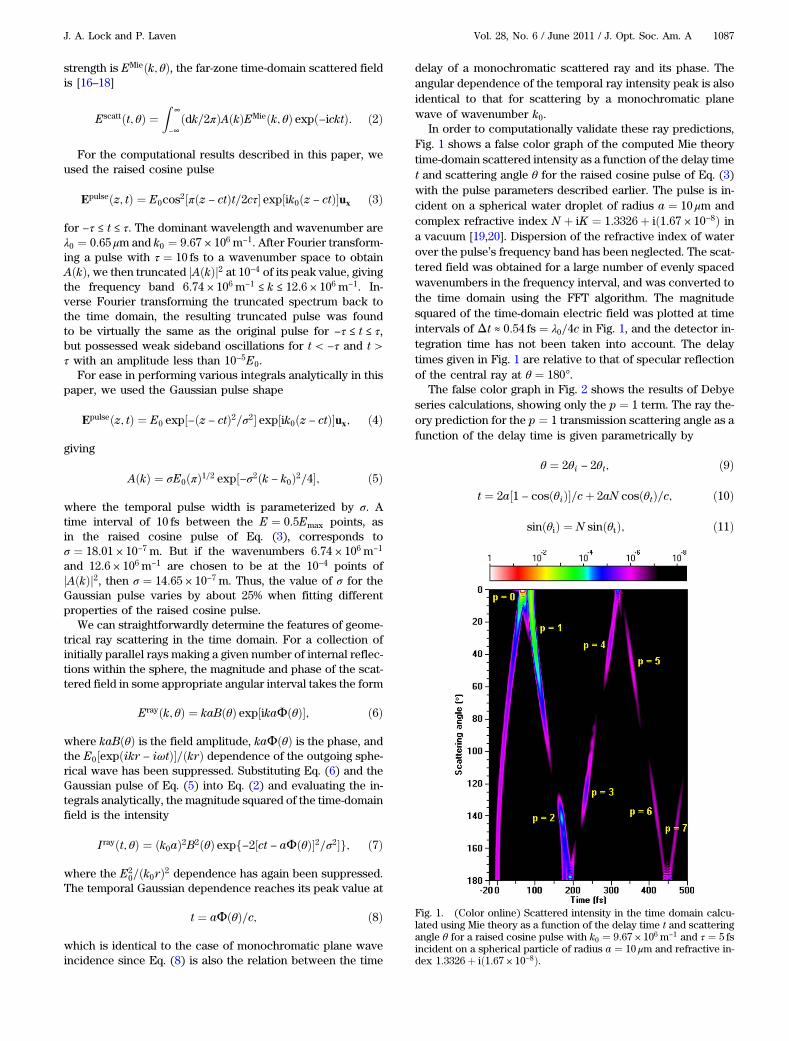
In order to computationally validate these ray predictions,Fig. 1 shows a false color graph of the computed Mie theorytime-domain scattered intensity as a function of the delay timet and scattering angle θ for the raised cosine pulse of Eq. (3)with the pulse parameters described earlier. The pulse is in-cident on a spherical water droplet of radius a ¼ 10 μm andcomplex refractive index N þ iK ¼ 1:3326þ ið1:67 × 10−8Þ ina vacuum [19,20]. Dispersion of the refractive index of waterover the pulse’s frequency band has been neglected. The scat-tered field was obtained for a large number of evenly spacedwavenumbers in the frequency interval, and was converted tothe time domain using the FFT algorithm. The magnitudesquared of the time-domain electric field was plotted at timeintervals of Δt ≈ 0:54 fs ¼ λ0=4c in Fig. 1, and the detector in-tegration time has not been taken into account. The delaytimes given in Fig. 1 are relative to that of specular reflectionof the central ray at θ ¼ 180°.
The false color graph in Fig. 2 shows the results of Debyeseries calculations, showing only the p ¼ 1 term. The ray the-ory prediction for the p ¼ 1 transmission scattering angle as afunction of the delay time is given parametrically by
θ ¼ 2θi − 2θt; ð9Þ
t ¼ 2a½1 − cosðθiÞ�=cþ 2aN cosðθtÞ=c; ð10Þ
sinðθiÞ ¼ N sinðθtÞ; ð11Þ
Fig. 1. (Color online) Scattered intensity in the time domain calcu-lated using Mie theory as a function of the delay time t and scatteringangle θ for a raised cosine pulse with k0 ¼ 9:67 × 106 m−1 and τ ¼ 5 fsincident on a spherical particle of radius a ¼ 10 μm and refractive in-dex 1:3326þ ið1:67 × 10−8Þ.
J. A. Lock and P. Laven Vol. 28, No. 6 / June 2011 / J. Opt. Soc. Am. A 1087
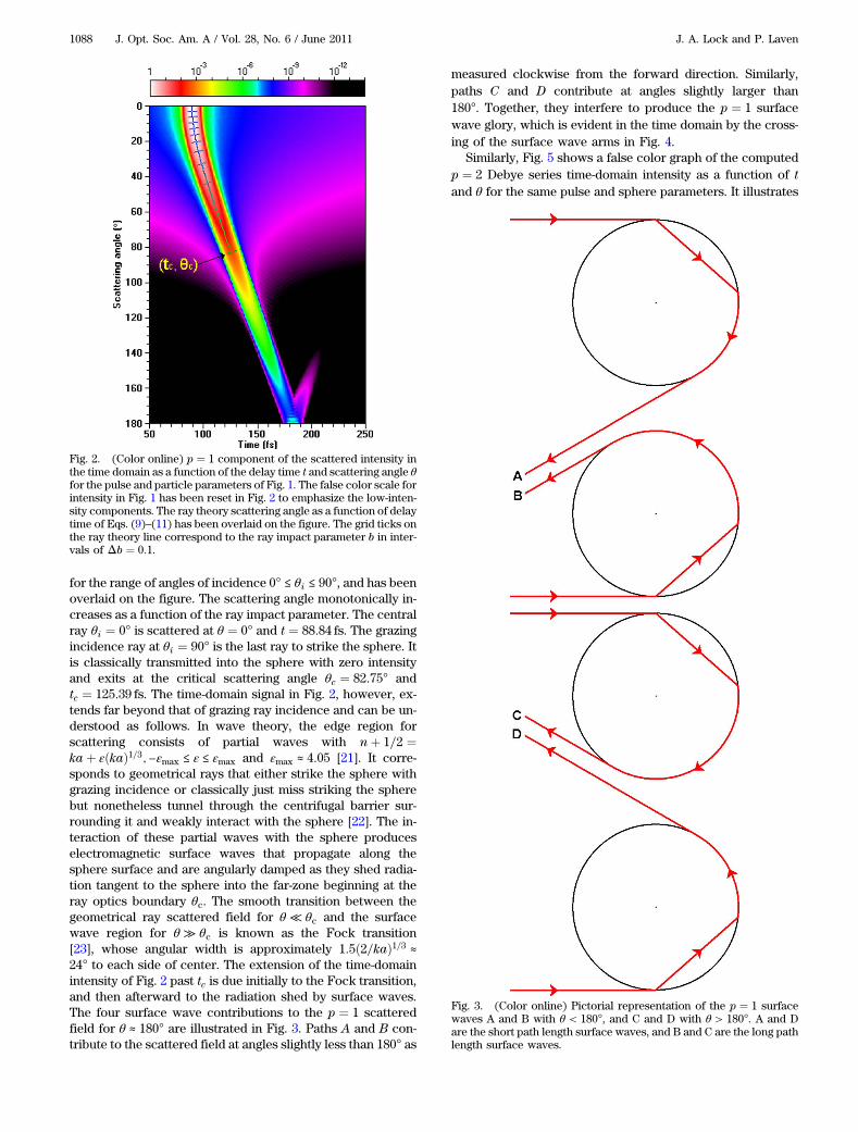
for the range of angles of incidence 0° ≤ θi ≤ 90°, and has beenoverlaid on the figure. The scattering angle monotonically in-creases as a function of the ray impact parameter. The centralray θi ¼ 0° is scattered at θ ¼ 0° and t ¼ 88:84 fs. The grazingincidence ray at θi ¼ 90° is the last ray to strike the sphere. Itis classically transmitted into the sphere with zero intensityand exits at the critical scattering angle θc ¼ 82:75° andtc ¼ 125:39 fs. The time-domain signal in Fig. 2, however, ex-tends far beyond that of grazing ray incidence and can be un-derstood as follows. In wave theory, the edge region forscattering consists of partial waves with nþ 1=2 ¼kaþ εðkaÞ1=3;−εmax ≤ ε ≤ εmax and εmax ≈ 4:05 [21]. It corre-sponds to geometrical rays that either strike the sphere withgrazing incidence or classically just miss striking the spherebut nonetheless tunnel through the centrifugal barrier sur-rounding it and weakly interact with the sphere [22]. The in-teraction of these partial waves with the sphere produceselectromagnetic surface waves that propagate along thesphere surface and are angularly damped as they shed radia-tion tangent to the sphere into the far-zone beginning at theray optics boundary θc. The smooth transition between thegeometrical ray scattered field for θ ≪ θc and the surfacewave region for θ ≫ θc is known as the Fock transition[23], whose angular width is approximately 1:5ð2=kaÞ1=3 ≈24° to each side of center. The extension of the time-domainintensity of Fig. 2 past tc is due initially to the Fock transition,and then afterward to the radiation shed by surface waves.The four surface wave contributions to the p ¼ 1 scatteredfield for θ ≈ 180° are illustrated in Fig. 3. Paths A and B con-tribute to the scattered field at angles slightly less than 180° as
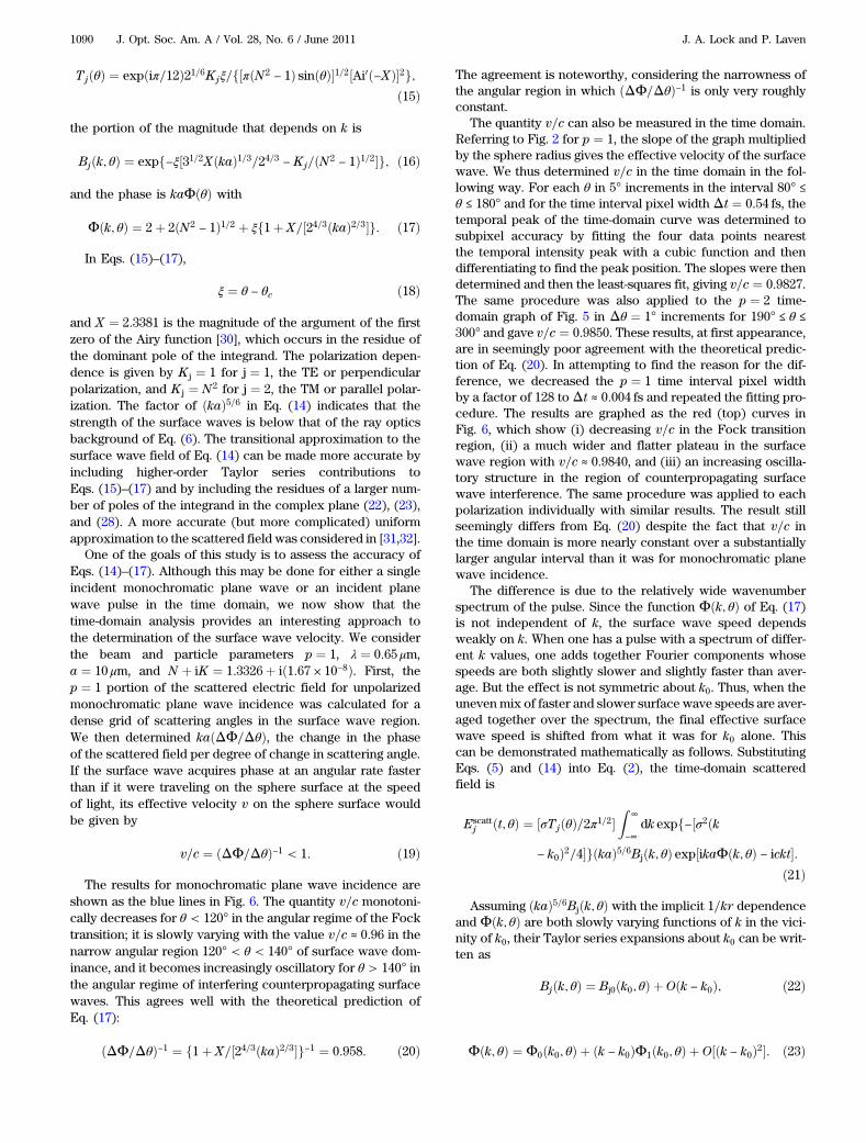
measured clockwise from the forward direction. Similarly,paths C and D contribute at angles slightly larger than180°. Together, they interfere to produce the p ¼ 1 surfacewave glory, which is evident in the time domain by the cross-ing of the surface wave arms in Fig. 4.
Similarly, Fig. 5 shows a false color graph of the computedp ¼ 2 Debye series time-domain intensity as a function of tand θ for the same pulse and sphere parameters. It illustrates
Fig. 2. (Color online) p ¼ 1 component of the scattered intensity inthe time domain as a function of the delay time t and scattering angle θfor the pulse and particle parameters of Fig. 1. The false color scale forintensity in Fig. 1 has been reset in Fig. 2 to emphasize the low-inten-sity components. The ray theory scattering angle as a function of delaytime of Eqs. (9)–(11) has been overlaid on the figure. The grid ticks onthe ray theory line correspond to the ray impact parameter b in inter-vals of Δb ¼ 0:1.
Fig. 3. (Color online) Pictorial representation of the p ¼ 1 surfacewaves A and B with θ < 180°, and C and D with θ > 180°. A and Dare the short path length surface waves, and B and C are the long pathlength surface waves.
1088 J. Opt. Soc. Am. A / Vol. 28, No. 6 / June 2011 J. A. Lock and P. Laven
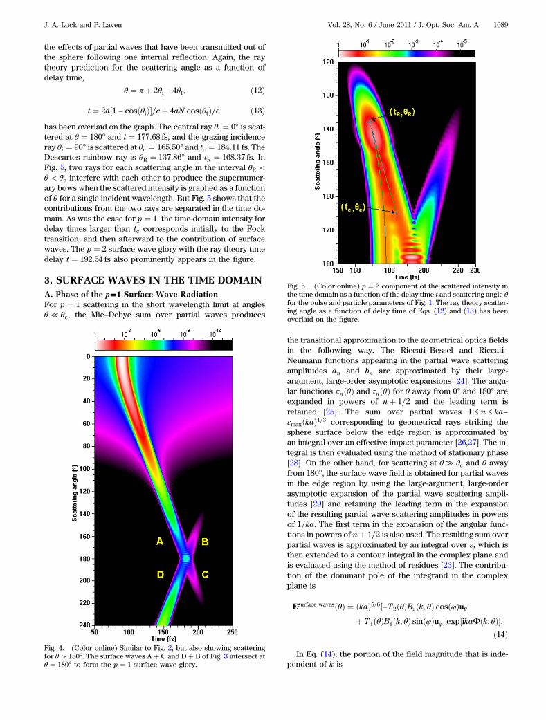
the effects of partial waves that have been transmitted out ofthe sphere following one internal reflection. Again, the raytheory prediction for the scattering angle as a function ofdelay time,
θ ¼ π þ 2θi − 4θt; ð12Þ
t ¼ 2a½1 − cosðθiÞ�=cþ 4aN cosðθtÞ=c; ð13Þhas been overlaid on the graph. The central ray θi ¼ 0° is scat-tered at θ ¼ 180° and t ¼ 177:68 fs, and the grazing incidenceray θi ¼ 90° is scattered at θc ¼ 165:50° and tc ¼ 184:11 fs. TheDescartes rainbow ray is θR ¼ 137:86° and tR ¼ 168:37 fs. InFig. 5, two rays for each scattering angle in the interval θR <θ < θc interfere with each other to produce the supernumer-ary bows when the scattered intensity is graphed as a functionof θ for a single incident wavelength. But Fig. 5 shows that thecontributions from the two rays are separated in the time do-main. As was the case for p ¼ 1, the time-domain intensity fordelay times larger than tc corresponds initially to the Focktransition, and then afterward to the contribution of surfacewaves. The p ¼ 2 surface wave glory with the ray theory timedelay t ¼ 192:54 fs also prominently appears in the figure.
3. SURFACE WAVES IN THE TIME DOMAINA. Phase of the p�1 Surface Wave RadiationFor p ¼ 1 scattering in the short wavelength limit at anglesθ ≪ θc, the Mie–Debye sum over partial waves produces
the transitional approximation to the geometrical optics fieldsin the following way. The Riccati–Bessel and Riccati–Neumann functions appearing in the partial wave scatteringamplitudes an and bn are approximated by their large-argument, large-order asymptotic expansions [24]. The angu-lar functions πnðθÞ and τnðθÞ for θ away from 0° and 180° areexpanded in powers of nþ 1=2 and the leading term isretained [25]. The sum over partial waves 1 ≤ n ≤ ka−εmaxðkaÞ1=3 corresponding to geometrical rays striking thesphere surface below the edge region is approximated byan integral over an effective impact parameter [26,27]. The in-tegral is then evaluated using the method of stationary phase[28]. On the other hand, for scattering at θ ≫ θc and θ awayfrom 180°, the surface wave field is obtained for partial wavesin the edge region by using the large-argument, large-orderasymptotic expansion of the partial wave scattering ampli-tudes [29] and retaining the leading term in the expansionof the resulting partial wave scattering amplitudes in powersof 1=ka. The first term in the expansion of the angular func-tions in powers of nþ 1=2 is also used. The resulting sum overpartial waves is approximated by an integral over ε, which isthen extended to a contour integral in the complex plane andis evaluated using the method of residues [23]. The contribu-tion of the dominant pole of the integrand in the complexplane is
Esurface wavesðθÞ ¼ ðkaÞ5=6½−T2ðθÞB2ðk; θÞ cosðφÞuθþ T1ðθÞB1ðk; θÞ sinðφÞuφ� exp½ikaΦðk; θÞ�:
ð14Þ
In Eq. (14), the portion of the field magnitude that is inde-pendent of k is
Fig. 4. (Color online) Similar to Fig. 2, but also showing scatteringfor θ > 180°. The surface waves A þ C and Dþ B of Fig. 3 intersect atθ ¼ 180° to form the p ¼ 1 surface wave glory.
Fig. 5. (Color online) p ¼ 2 component of the scattered intensity inthe time domain as a function of the delay time t and scattering angle θfor the pulse and particle parameters of Fig. 1. The ray theory scatter-ing angle as a function of delay time of Eqs. (12) and (13) has beenoverlaid on the figure.
J. A. Lock and P. Laven Vol. 28, No. 6 / June 2011 / J. Opt. Soc. Am. A 1089
TjðθÞ ¼ expðiπ=12Þ21=6Kjξ=f½πðN2− 1Þ sinðθÞ�1=2½Ai0ð−XÞ�2g;
ð15Þ
the portion of the magnitude that depends on k is
Bjðk; θÞ ¼ expf−ξ½31=2XðkaÞ1=3=24=3 − Kj=ðN2− 1Þ1=2�g; ð16Þ
and the phase is kaΦðθÞ with
Φðk; θÞ ¼ 2þ 2ðN2− 1Þ1=2 þ ξf1þ X=½24=3ðkaÞ2=3�g: ð17Þ
In Eqs. (15)–(17),
ξ ¼ θ − θc ð18Þ
and X ¼ 2:3381 is the magnitude of the argument of the firstzero of the Airy function [30], which occurs in the residue ofthe dominant pole of the integrand. The polarization depen-dence is given by K j ¼ 1 for j ¼ 1, the TE or perpendicularpolarization, and K j ¼ N2 for j ¼ 2, the TM or parallel polar-ization. The factor of ðkaÞ5=6 in Eq. (14) indicates that thestrength of the surface waves is below that of the ray opticsbackground of Eq. (6). The transitional approximation to thesurface wave field of Eq. (14) can be made more accurate byincluding higher-order Taylor series contributions toEqs. (15)–(17) and by including the residues of a larger num-ber of poles of the integrand in the complex plane (22), (23),and (28). A more accurate (but more complicated) uniformapproximation to the scattered field was considered in [31,32].
One of the goals of this study is to assess the accuracy ofEqs. (14)–(17). Although this may be done for either a singleincident monochromatic plane wave or an incident planewave pulse in the time domain, we now show that thetime-domain analysis provides an interesting approach tothe determination of the surface wave velocity. We considerthe beam and particle parameters p ¼ 1, λ ¼ 0:65 μm,a ¼ 10 μm, and N þ iK ¼ 1:3326þ ið1:67 × 10−8Þ. First, thep ¼ 1 portion of the scattered electric field for unpolarizedmonochromatic plane wave incidence was calculated for adense grid of scattering angles in the surface wave region.We then determined kaðΔΦ=ΔθÞ, the change in the phaseof the scattered field per degree of change in scattering angle.If the surface wave acquires phase at an angular rate fasterthan if it were traveling on the sphere surface at the speedof light, its effective velocity v on the sphere surface wouldbe given by
v=c ¼ ðΔΦ=ΔθÞ−1 < 1: ð19Þ
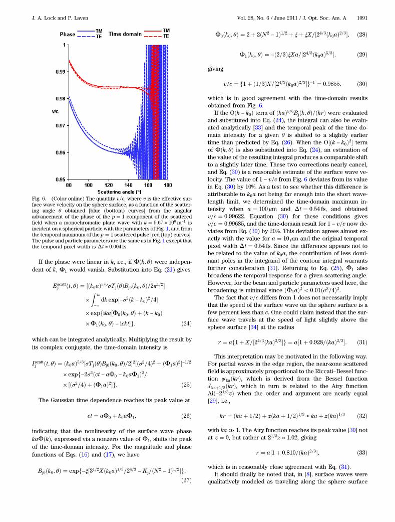
The results for monochromatic plane wave incidence areshown as the blue lines in Fig. 6. The quantity v=c monotoni-cally decreases for θ < 120° in the angular regime of the Focktransition; it is slowly varying with the value v=c ≈ 0:96 in thenarrow angular region 120° < θ < 140° of surface wave dom-inance, and it becomes increasingly oscillatory for θ > 140° inthe angular regime of interfering counterpropagating surfacewaves. This agrees well with the theoretical prediction ofEq. (17):
ðΔΦ=ΔθÞ−1 ¼ f1þ X=½24=3ðkaÞ2=3�g−1 ¼ 0:958: ð20Þ
The agreement is noteworthy, considering the narrowness ofthe angular region in which ðΔΦ=ΔθÞ−1 is only very roughlyconstant.
The quantity v=c can also be measured in the time domain.Referring to Fig. 2 for p ¼ 1, the slope of the graph multipliedby the sphere radius gives the effective velocity of the surfacewave. We thus determined v=c in the time domain in the fol-lowing way. For each θ in 5° increments in the interval 80° ≤θ ≤ 180° and for the time interval pixel width Δt ¼ 0:54 fs, thetemporal peak of the time-domain curve was determined tosubpixel accuracy by fitting the four data points nearestthe temporal intensity peak with a cubic function and thendifferentiating to find the peak position. The slopes were thendetermined and then the least-squares fit, giving v=c ¼ 0:9827.The same procedure was also applied to the p ¼ 2 time-domain graph of Fig. 5 in Δθ ¼ 1° increments for 190° ≤ θ ≤
300° and gave v=c ¼ 0:9850. These results, at first appearance,are in seemingly poor agreement with the theoretical predic-tion of Eq. (20). In attempting to find the reason for the dif-ference, we decreased the p ¼ 1 time interval pixel widthby a factor of 128 to Δt ≈ 0:004 fs and repeated the fitting pro-cedure. The results are graphed as the red (top) curves inFig. 6, which show (i) decreasing v=c in the Fock transitionregion, (ii) a much wider and flatter plateau in the surfacewave region with v=c ≈ 0:9840, and (iii) an increasing oscilla-tory structure in the region of counterpropagating surfacewave interference. The same procedure was applied to eachpolarization individually with similar results. The result stillseemingly differs from Eq. (20) despite the fact that v=c inthe time domain is more nearly constant over a substantiallylarger angular interval than it was for monochromatic planewave incidence.
The difference is due to the relatively wide wavenumberspectrum of the pulse. Since the function Φðk; θÞ of Eq. (17)is not independent of k, the surface wave speed dependsweakly on k. When one has a pulse with a spectrum of differ-ent k values, one adds together Fourier components whosespeeds are both slightly slower and slightly faster than aver-age. But the effect is not symmetric about k0. Thus, when theunevenmix of faster and slower surface wave speeds are aver-aged together over the spectrum, the final effective surfacewave speed is shifted from what it was for k0 alone. Thiscan be demonstrated mathematically as follows. SubstitutingEqs. (5) and (14) into Eq. (2), the time-domain scatteredfield is
Escattj ðt; θÞ ¼ ½σTjðθÞ=2π1=2�
Z∞
−∞
dk expf−½σ2ðk
− k0Þ2=4�gðkaÞ5=6Bjðk; θÞ exp½ikaΦðk; θÞ − ickt�:ð21Þ
Assuming ðkaÞ5=6Bjðk; θÞ with the implicit 1=kr dependenceand Φðk; θÞ are both slowly varying functions of k in the vici-nity of k0, their Taylor series expansions about k0 can be writ-ten as
Bjðk; θÞ ¼ Bj0ðk0; θÞ þ Oðk − k0Þ; ð22Þ
Φðk; θÞ ¼ Φ0ðk0; θÞ þ ðk − k0ÞΦ1ðk0; θÞ þ O½ðk − k0Þ2�: ð23Þ
1090 J. Opt. Soc. Am. A / Vol. 28, No. 6 / June 2011 J. A. Lock and P. Laven
If the phase were linear in k, i.e., if Φðk; θÞ were indepen-dent of k, Φ1 would vanish. Substitution into Eq. (21) gives
Escattj ðt; θÞ ¼ ½ðk0aÞ5=6σT jðθÞBj0ðk0; θÞ=2π1=2�
×Z
∞
−∞
dk exp½−σ2ðk − k0Þ2=4�
× expfika½Φ0ðk0; θÞ þ ðk − k0Þ×Φ1ðk0; θÞ − ickt�g; ð24Þ
which can be integrated analytically. Multiplying the result byits complex conjugate, the time-domain intensity is
Iscattj ðt; θÞ ¼ ðk0aÞ5=3½σT jðθÞBj0ðk0; θÞ=2�2½ðσ2=4Þ2 þ ðΦ1aÞ2�−1=2× expf−2σ2ðct − aΦ0 − k0aΦ1Þ2=× ½ðσ2=4Þ þ ðΦ1aÞ2�g: ð25Þ
The Gaussian time dependence reaches its peak value at
ct ¼ aΦ0 þ k0aΦ1; ð26Þ
indicating that the nonlinearity of the surface wave phasekaΦðkÞ, expressed via a nonzero value of Φ1, shifts the peakof the time-domain intensity. For the magnitude and phasefunctions of Eqs. (16) and (17), we have
Bj0ðk0; θÞ ¼ expf−ξ½31=2Xðk0aÞ1=3=24=3 − K j=ðN2− 1Þ1=2�g;
ð27Þ
Φ0ðk0; θÞ ¼ 2þ 2ðN2− 1Þ1=2 þ ξþ ξX=½24=3ðk0aÞ2=3�; ð28Þ
Φ1ðk0; θÞ ¼ −ð2=3ÞξXa=½24=3ðk0aÞ5=3�; ð29Þ
giving
v=c ¼ f1þ ð1=3ÞX=½24=3ðk0aÞ2=3�g−1 ¼ 0:9855; ð30Þ
which is in good agreement with the time-domain resultsobtained from Fig. 6.
If the Oðk − k0Þ term of ðkaÞ5=6Bjðk; θÞ=ðkrÞ were evaluatedand substituted into Eq. (24), the integral can also be evalu-ated analytically [33] and the temporal peak of the time do-main intensity for a given θ is shifted to a slightly earliertime than predicted by Eq. (26). When the O½ðk − k0Þ2� termof Φðk; θÞ is also substituted into Eq. (24), an estimation ofthe value of the resulting integral produces a comparable shiftto a slightly later time. These two corrections nearly cancel,and Eq. (30) is a reasonable estimate of the surface wave ve-locity. The value of 1 − v=c from Fig. 6 deviates from its valuein Eq. (30) by 10%. As a test to see whether this difference isattributable to k0a not being far enough into the short wave-length limit, we determined the time-domain maximum in-tensity when a ¼ 100 μm and Δt ¼ 0:54 fs, and obtainedv=c ¼ 0:99622. Equation (30) for these conditions givesv=c ¼ 0:99685, and the time-domain result for 1 − v=c now de-viates from Eq. (30) by 20%. This deviation agrees almost ex-actly with the value for a ¼ 10 μm and the original temporalpixel width Δt ¼ 0:54 fs. Since the difference appears not tobe related to the value of k0a, the contribution of less domi-nant poles in the integrand of the contour integral warrantsfurther consideration [31]. Returning to Eq. (25), Φ1 alsobroadens the temporal response for a given scattering angle.However, for the beam and particle parameters used here, thebroadening is minimal since ðΦ1aÞ2 < 0:01ðσ2=4Þ2.
The fact that v=c differs from 1 does not necessarily implythat the speed of the surface wave on the sphere surface is afew percent less than c. One could claim instead that the sur-face wave travels at the speed of light slightly above thesphere surface [34] at the radius
r ¼ af1þ X=½24=3ðkaÞ2=3�g ¼ a½1þ 0:928=ðkaÞ2=3�: ð31Þ
This interpretation may be motivated in the following way.For partial waves in the edge region, the near-zone scatteredfield is approximately proportional to the Riccati–Bessel func-tion ψkaðkrÞ, which is derived from the Bessel functionJkaþ1=2ðkrÞ, which in turn is related to the Airy functionAið−21=3zÞ when the order and argument are nearly equal[29], i.e.,
kr ¼ ðkaþ 1=2Þ þ zðkaþ 1=2Þ1=3 ≈ kaþ zðkaÞ1=3 ð32Þ
with ka ≫ 1. The Airy function reaches its peak value [30] notat z ¼ 0, but rather at 21=3z ≈ 1:02, giving
r ¼ a½1þ 0:810=ðkaÞ2=3�; ð33Þ
which is in reasonably close agreement with Eq. (31).It should finally be noted that, in [8], surface waves were
qualitatively modeled as traveling along the sphere surface
Fig. 6. (Color online) The quantity v=c, where v is the effective sur-face wave velocity on the sphere surface, as a function of the scatter-ing angle θ obtained [blue (bottom) curves] from the angularadvancement of the phase of the p ¼ 1 component of the scatteredfield when a monochromatic plane wave with k ¼ 9:67 × 106 m−1 isincident on a spherical particle with the parameters of Fig. 1, and fromthe temporal maximum of the p ¼ 1 scattered pulse [red (top) curves].The pulse and particle parameters are the same as in Fig. 1 except thatthe temporal pixel width is Δt ≈ 0:004 fs.
J. A. Lock and P. Laven Vol. 28, No. 6 / June 2011 / J. Opt. Soc. Am. A 1091
for the entirety of their path, and the refractive index of thesphere surface was allowed to be variable. In order to matchthe computed time delay and the time delay predicted usingthis model, a value of the surface refractive index was ob-tained that was intermediate between that of the sphere inter-ior and the exterior medium. A more mathematically detailedinterpretation of the surface wave path that includes shortcuts through the sphere, however, was presented and physi-cally motivated in [22] and is used in this paper to interpret ourresults.
B. Magnitude of the p � 2 Surface Wave RadiationSince the angular extent of the p ¼ 2 surface wave region inFig. 5 without the intrusion of the glory region is much largerthan for p ¼ 1 surface waves in Fig. 2, we examine here theangular damping rate of the p ¼ 2 surface wave intensity. Thederivation of the expression analogous to Eqs. (14)–(17) forthe p ¼ 2 surface wave proceeds exactly as for p ¼ 1, exceptthat the poles of the p ¼ 2 integrand of the contour integralare of a higher order than for p ¼ 1. The only change inEqs. (14)–(17) made by this more complicated residue is thatT jðθÞ is proportional to a mixture of ξ2 and ξ rather than to ξalone. This slightly changes its behavior for θ ≈ θc where thesurface wave expression is dominated by the Fock transition,but it will not change the exponential attenuation for θ ≫ θc.Since ðΦ1aÞ2 ≪ ðσ2=4Þ4 and the resulting broadening of thetime-domain response is minimal, a comparison of the magni-tude squared of Eq. (14) with Eq. (25) shows that the value ofthe peak intensity as a function of θ in the time domain is iden-tical to the value of the scattered intensity as a function of θfor monochromatic plane wave incidence. Thus, it shouldmake no difference whether the surface wave damping rateis measured in the time domain or for monochromatic planewave incidence.
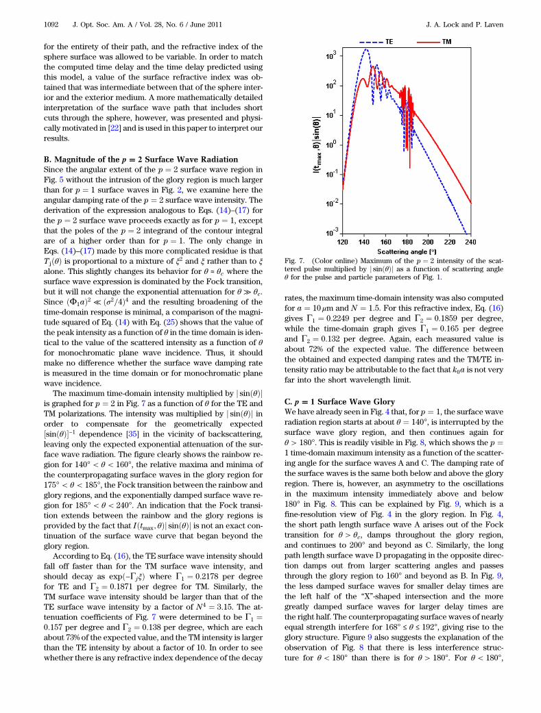
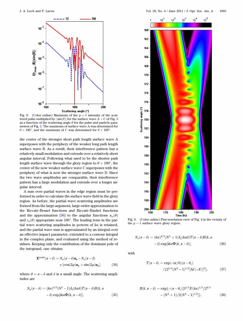
The maximum time-domain intensity multiplied by j sinðθÞjis graphed for p ¼ 2 in Fig. 7 as a function of θ for the TE andTM polarizations. The intensity was multiplied by j sinðθÞj inorder to compensate for the geometrically expected½sinðθÞ�−1 dependence [35] in the vicinity of backscattering,leaving only the expected exponential attenuation of the sur-face wave radiation. The figure clearly shows the rainbow re-gion for 140° < θ < 160°, the relative maxima and minima ofthe counterpropagating surface waves in the glory region for175° < θ < 185°, the Fock transition between the rainbow andglory regions, and the exponentially damped surface wave re-gion for 185° < θ < 240°. An indication that the Fock transi-tion extends between the rainbow and the glory regions isprovided by the fact that Iðtmax; θÞj sinðθÞj is not an exact con-tinuation of the surface wave curve that began beyond theglory region.
According to Eq. (16), the TE surface wave intensity shouldfall off faster than for the TM surface wave intensity, andshould decay as expð−ΓjξÞ where Γ1 ¼ 0:2178 per degreefor TE and Γ2 ¼ 0:1871 per degree for TM. Similarly, theTM surface wave intensity should be larger than that of theTE surface wave intensity by a factor of N4 ¼ 3:15. The at-tenuation coefficients of Fig. 7 were determined to be Γ1 ¼0:157 per degree and Γ2 ¼ 0:138 per degree, which are eachabout 73% of the expected value, and the TM intensity is largerthan the TE intensity by about a factor of 10. In order to seewhether there is any refractive index dependence of the decay
rates, the maximum time-domain intensity was also computedfor a ¼ 10 μm and N ¼ 1:5. For this refractive index, Eq. (16)gives Γ1 ¼ 0:2249 per degree and Γ2 ¼ 0:1859 per degree,while the time-domain graph gives Γ1 ¼ 0:165 per degreeand Γ2 ¼ 0:132 per degree. Again, each measured value isabout 72% of the expected value. The difference betweenthe obtained and expected damping rates and the TM/TE in-tensity ratio may be attributable to the fact that k0a is not veryfar into the short wavelength limit.
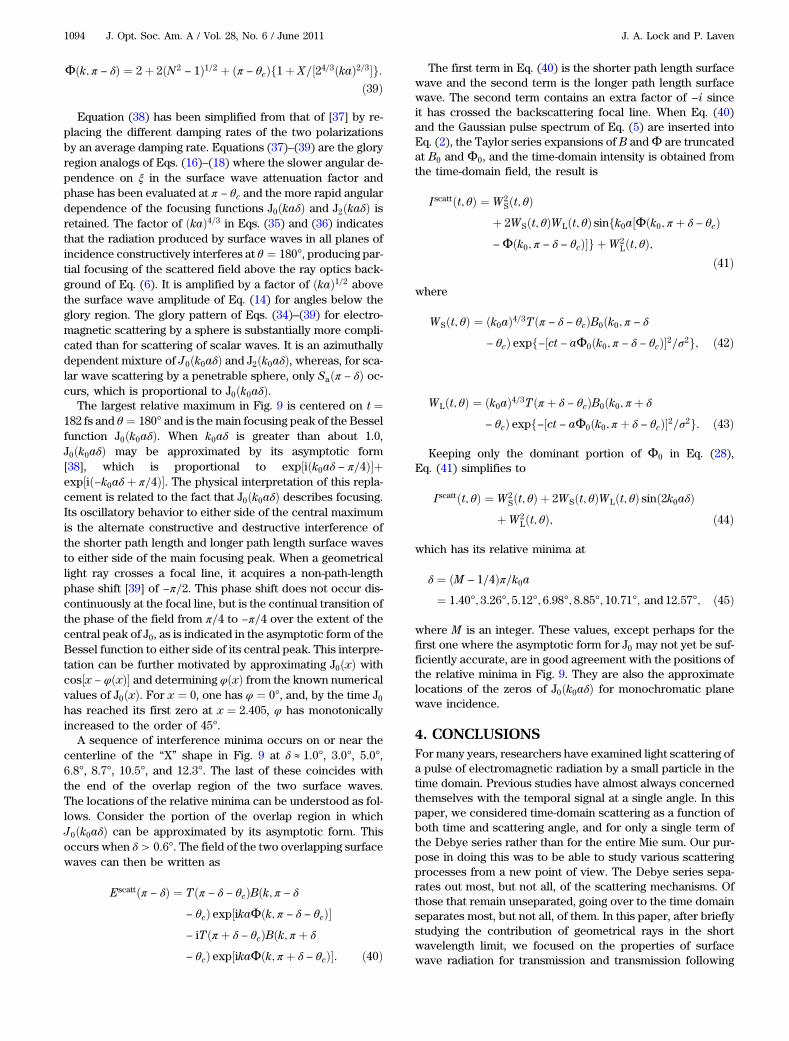
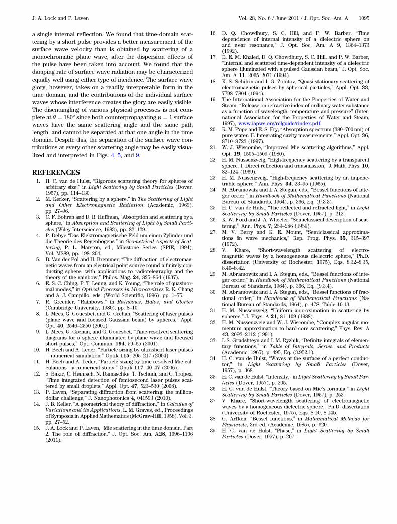
C. p � 1 Surface Wave GloryWe have already seen in Fig. 4 that, for p ¼ 1, the surface waveradiation region starts at about θ ¼ 140°, is interrupted by thesurface wave glory region, and then continues again forθ > 180°. This is readily visible in Fig. 8, which shows the p ¼1 time-domain maximum intensity as a function of the scatter-ing angle for the surface waves A and C. The damping rate ofthe surface waves is the same both below and above the gloryregion. There is, however, an asymmetry to the oscillationsin the maximum intensity immediately above and below180° in Fig. 8. This can be explained by Fig. 9, which is afine-resolution view of Fig. 4 in the glory region. In Fig. 4,the short path length surface wave A arises out of the Focktransition for θ > θc, damps throughout the glory region,and continues to 200° and beyond as C. Similarly, the longpath length surface wave D propagating in the opposite direc-tion damps out from larger scattering angles and passesthrough the glory region to 160° and beyond as B. In Fig. 9,the less damped surface waves for smaller delay times arethe left half of the “X”-shaped intersection and the moregreatly damped surface waves for larger delay times arethe right half. The counterpropagating surface waves of nearlyequal strength interfere for 168° ≤ θ ≤ 192°, giving rise to theglory structure. Figure 9 also suggests the explanation of theobservation of Fig. 8 that there is less interference struc-ture for θ < 180° than there is for θ > 180°. For θ < 180°,
Fig. 7. (Color online) Maximum of the p ¼ 2 intensity of the scat-tered pulse multiplied by j sinðθÞj as a function of scattering angleθ for the pulse and particle parameters of Fig. 1.
1092 J. Opt. Soc. Am. A / Vol. 28, No. 6 / June 2011 J. A. Lock and P. Laven
the center of the stronger short path length surface wave Asuperposes with the periphery of the weaker long path lengthsurface wave B. As a result, their interference pattern has arelatively small modulation and extends over a relatively shortangular interval. Following what used to be the shorter pathlength surface wave through the glory region to θ > 180°, thecenter of the now weaker surface wave C superposes with theperiphery of what is now the stronger surface wave D. Sincethe two wave amplitudes are comparable, their interferencepattern has a large modulation and extends over a longer an-gular interval.
A sum over partial waves in the edge region must be per-formed in order to calculate the surface wave field in the gloryregion. As before, the partial wave scattering amplitudes areformed from the large-argument, large-order approximation tothe Riccati–Bessel functions and Riccati–Hankel functionsand the approximation [36] to the angular functions πnðθÞand τnðθÞ appropriate near 180°. The leading term in the par-tial wave scattering amplitudes in powers of ka is retained,and the partial wave sum is approximated by an integral overan effective impact parameter, extended to a contour integralin the complex plane, and evaluated using the method of re-sidues. Keeping only the contribution of the dominant pole ofthe integrand, one obtains
Escattðπ − δÞ ¼ Saðπ − δÞux − Ssðπ − δÞ× ½cosð2φÞux þ sinð2φÞuy�; ð34Þ
where θ ¼ π − δ and δ is a small angle. The scattering ampli-tudes are
Saðπ − δÞ ¼ ðkaÞ4=3ðN2− 1ÞJ0ðkaδÞTðπ − δÞBðk; π
− δÞ exp½ikaΦðk; π − δÞ�; ð35Þ
Ssðπ − δÞ ¼ ðkaÞ4=3ðN2 þ 1ÞJ2ðkaδÞTðπ − δÞBðk; π− δÞ exp½ikaΦðk; π − δÞ�; ð36Þ
with
Tðπ − δÞ ¼ expð−iπ=6Þðπ − θcÞ=f21=3ðN2
− 1Þ1=2½Ai0ð−XÞ�2g; ð37Þ
Bðk; π − δÞ ¼ expf−ðπ − θcÞ½31=2XðkaÞ1=3=24=3− ðN2 þ 1Þ=2ðN2
− 1Þ1=2�g; ð38Þ
Fig. 8. (Color online) Maximum of the p ¼ 1 intensity of the scat-tered pulse multiplied by j sinðθÞj for the surface wave A þ C of Fig. 3as a function of the scattering angle θ for the pulse and particle para-meters of Fig. 1. The maximum of surface wave A was determined forθ < 180°, and the maximum of C was determined for θ > 180°.
Fig. 9. (Color online) Fine-resolution view of Fig. 4 in the vicinity ofthe p ¼ 1 surface wave glory region.
J. A. Lock and P. Laven Vol. 28, No. 6 / June 2011 / J. Opt. Soc. Am. A 1093
Φðk; π − δÞ ¼ 2þ 2ðN2− 1Þ1=2 þ ðπ − θcÞf1þ X=½24=3ðkaÞ2=3�g:
ð39Þ
Equation (38) has been simplified from that of [37] by re-placing the different damping rates of the two polarizationsby an average damping rate. Equations (37)–(39) are the gloryregion analogs of Eqs. (16)–(18) where the slower angular de-pendence on ξ in the surface wave attenuation factor andphase has been evaluated at π − θc and the more rapid angulardependence of the focusing functions J0ðkaδÞ and J2ðkaδÞ isretained. The factor of ðkaÞ4=3 in Eqs. (35) and (36) indicatesthat the radiation produced by surface waves in all planes ofincidence constructively interferes at θ ¼ 180°, producing par-tial focusing of the scattered field above the ray optics back-ground of Eq. (6). It is amplified by a factor of ðkaÞ1=2 abovethe surface wave amplitude of Eq. (14) for angles below theglory region. The glory pattern of Eqs. (34)–(39) for electro-magnetic scattering by a sphere is substantially more compli-cated than for scattering of scalar waves. It is an azimuthallydependent mixture of J0ðk0aδÞ and J2ðk0aδÞ, whereas, for sca-lar wave scattering by a penetrable sphere, only Saðπ − δÞ oc-curs, which is proportional to J0ðk0aδÞ.
The largest relative maximum in Fig. 9 is centered on t ¼182 fs and θ ¼ 180° and is the main focusing peak of the Besselfunction J0ðk0aδÞ. When k0aδ is greater than about 1.0,J0ðk0aδÞ may be approximated by its asymptotic form[38], which is proportional to exp½iðk0aδ − π=4Þ�þexp½ið−k0aδþ π=4Þ�. The physical interpretation of this repla-cement is related to the fact that J0ðk0aδÞ describes focusing.Its oscillatory behavior to either side of the central maximumis the alternate constructive and destructive interference ofthe shorter path length and longer path length surface wavesto either side of the main focusing peak. When a geometricallight ray crosses a focal line, it acquires a non-path-lengthphase shift [39] of −π=2. This phase shift does not occur dis-continuously at the focal line, but is the continual transition ofthe phase of the field from π=4 to −π=4 over the extent of thecentral peak of J0, as is indicated in the asymptotic form of theBessel function to either side of its central peak. This interpre-tation can be further motivated by approximating J0ðxÞ withcos½x − φðxÞ� and determining φðxÞ from the known numericalvalues of J0ðxÞ. For x ¼ 0, one has φ ¼ 0°, and, by the time J0has reached its first zero at x ¼ 2:405, φ has monotonicallyincreased to the order of 45°.
A sequence of interference minima occurs on or near thecenterline of the “X” shape in Fig. 9 at δ ≈ 1:0°, 3:0°, 5:0°,6:8°, 8:7°, 10:5°, and 12:3°. The last of these coincides withthe end of the overlap region of the two surface waves.The locations of the relative minima can be understood as fol-lows. Consider the portion of the overlap region in whichJ0ðk0aδÞ can be approximated by its asymptotic form. Thisoccurs when δ > 0:6°. The field of the two overlapping surfacewaves can then be written as
Escattðπ − δÞ ¼ Tðπ − δ − θcÞBðk; π − δ− θcÞ exp½ikaΦðk; π − δ − θcÞ�− iTðπ þ δ − θcÞBðk; π þ δ− θcÞ exp½ikaΦðk; π þ δ − θcÞ�: ð40Þ
The first term in Eq. (40) is the shorter path length surfacewave and the second term is the longer path length surfacewave. The second term contains an extra factor of −i sinceit has crossed the backscattering focal line. When Eq. (40)and the Gaussian pulse spectrum of Eq. (5) are inserted intoEq. (2), the Taylor series expansions of B andΦ are truncatedat B0 and Φ0, and the time-domain intensity is obtained fromthe time-domain field, the result is
Iscattðt; θÞ ¼ W2Sðt; θÞ
þ 2WSðt; θÞWLðt; θÞ sinfk0a½Φðk0; π þ δ − θcÞ−Φðk0; π − δ − θcÞ�g þW2
Lðt; θÞ;ð41Þ
where
WSðt; θÞ ¼ ðk0aÞ4=3Tðπ − δ − θcÞB0ðk0; π − δ− θcÞ expf−½ct − aΦ0ðk0; π − δ − θcÞ�2=σ2g; ð42Þ
WLðt; θÞ ¼ ðk0aÞ4=3Tðπ þ δ − θcÞB0ðk0; π þ δ− θcÞ expf−½ct − aΦ0ðk0; π þ δ − θcÞ�2=σ2g: ð43Þ
Keeping only the dominant portion of Φ0 in Eq. (28),Eq. (41) simplifies to
Iscattðt; θÞ ¼ W2Sðt; θÞ þ 2WSðt; θÞWLðt; θÞ sinð2k0aδÞ
þW2Lðt; θÞ; ð44Þ
which has its relative minima at
δ ¼ ðM − 1=4Þπ=k0a¼ 1:40°; 3:26°; 5:12°; 6:98°; 8:85°; 10:71°; and 12:57°; ð45Þ
where M is an integer. These values, except perhaps for thefirst one where the asymptotic form for J0 may not yet be suf-ficiently accurate, are in good agreement with the positions ofthe relative minima in Fig. 9. They are also the approximatelocations of the zeros of J0ðk0aδÞ for monochromatic planewave incidence.
4. CONCLUSIONSFor many years, researchers have examined light scattering ofa pulse of electromagnetic radiation by a small particle in thetime domain. Previous studies have almost always concernedthemselves with the temporal signal at a single angle. In thispaper, we considered time-domain scattering as a function ofboth time and scattering angle, and for only a single term ofthe Debye series rather than for the entire Mie sum. Our pur-pose in doing this was to be able to study various scatteringprocesses from a new point of view. The Debye series sepa-rates out most, but not all, of the scattering mechanisms. Ofthose that remain unseparated, going over to the time domainseparates most, but not all, of them. In this paper, after brieflystudying the contribution of geometrical rays in the shortwavelength limit, we focused on the properties of surfacewave radiation for transmission and transmission following
1094 J. Opt. Soc. Am. A / Vol. 28, No. 6 / June 2011 J. A. Lock and P. Laven
a single internal reflection. We found that time-domain scat-tering by a short pulse provides a better measurement of thesurface wave velocity than is obtained by scattering of amonochromatic plane wave, after the dispersion effects ofthe pulse have been taken into account. We found that thedamping rate of surface wave radiation may be characterizedequally well using either type of incidence. The surface waveglory, however, takes on a readily interpretable form in thetime domain, and the contributions of the individual surfacewaves whose interference creates the glory are easily visible.The disentangling of various physical processes is not com-plete at θ ¼ 180° since both counterpropagating p ¼ 1 surfacewaves have the same scattering angle and the same pathlength, and cannot be separated at that one angle in the timedomain. Despite this, the separation of the surface wave con-tributions at every other scattering angle may be easily visua-lized and interpreted in Figs. 4, 5, and 9.
REFERENCES1. H. C. van de Hulst, “Rigorous scattering theory for spheres of
arbitrary size,” in Light Scattering by Small Particles (Dover,1957), pp. 114–130.
2. M. Kerker, “Scattering by a sphere,” in The Scattering of Light
and Other Electromagnetic Radiation (Academic, 1969),pp. 27–96.
3. C. F. Bohren and D. R. Huffman, “Absorption and scattering by asphere,” in Absorption and Scattering of Light by Small Parti-
cles (Wiley-Interscience, 1983), pp. 82–129.4. P. Debye “Das Elektromagnetische Feld um einen Zylinder und
die Theorie des Regenbogens,” in Geometrical Aspects of Scat-
tering, P. L. Marston, ed., Milestone Series (SPIE, 1994),Vol. MS89, pp. 198–204.
5. B. Van der Pol and H. Bremmer, “The diffraction of electromag-netic waves from an electrical point source round a finitely con-ducting sphere, with applications to radiotelegraphy and thetheory of the rainbow,” Philos. Mag. 24, 825–864 (1937).
6. E. S. C. Ching, P. T. Leung, and K. Young, “The role of quasinor-mal modes,” in Optical Processes in Microcavities R. K. Changand A. J. Campillo, eds. (World Scientific, 1996), pp. 1–75.
7. R. Greenler, “Rainbows,” in Rainbows, Halos, and Glories
(Cambridge University, 1980), pp. 8–10.8. L. Mees, G. Gouesbet, and G. Grehan, “Scattering of laser pulses
(plane wave and focused Gaussian beam) by spheres,” Appl.Opt. 40, 2546–2550 (2001).
9. L. Mees, G. Grehan, and G. Gouesbet, “Time-resolved scatteringdiagrams for a sphere illuminated by plane wave and focusedshort pulses,” Opt. Commun. 194, 59–65 (2001).
10. H. Bech and A. Leder, “Particle sizing by ultrashort laser pulses—numerical simulation,” Optik 115, 205–217 (2004).
11. H. Bech and A. Leder, “Particle sizing by time-resolved Mie cal-culations—a numerical study,” Optik 117, 40–47 (2006).
12. S. Bakic, C. Heinisch, N. Damaschke, T. Tschudi, and C. Tropea,“Time integrated detection of femtosecond laser pulses scat-tered by small droplets,” Appl. Opt. 47, 523–530 (2008).
13. P. Laven, “Separating diffraction from scattering: the million-dollar challenge,” J. Nanophotonics 4, 041593 (2010).
14. J. B. Keller, “A geometrical theory of diffraction,” in Calculus of
Variations and its Applications, L. M. Graves, ed., Proceedingsof Symposia in AppliedMathematics (McGraw-Hill, 1958), Vol. 3,pp. 27–52.
15. J. A. Lock and P. Laven, “Mie scattering in the time domain. Part2. The role of diffraction,” J. Opt. Soc. Am. A28, 1096–1106(2011).
16. D. Q. Chowdhury, S. C. Hill, and P. W. Barber, “Timedependence of internal intensity of a dielectric sphere onand near resonance,” J. Opt. Soc. Am. A 9, 1364–1373(1992).
17. E. E. M. Khaled, D. Q. Chowdhury, S. C. Hill, and P. W. Barber,“Internal and scattered time-dependent intensity of a dielectricsphere illuminated with a pulsed Gaussian beam,” J. Opt. Soc.Am. A 11, 2065–2071 (1994).
18. K. S. Schifrin and I. G. Zolotov, “Quasi-stationary scattering ofelectromagnetic pulses by spherical particles,” Appl. Opt. 33,7798–7804 (1994).
19. The International Association for the Properties of Water andSteam, “Release on refractive index of ordinary water substanceas a function of wavelength, temperature and pressure” (Inter-national Association for the Properties of Water and Steam,1997), www.iapws.org/relguide/rindex.pdf.
20. R. M. Pope and E. S. Fry, “Absorption spectrum (380–700nm) ofpure water. II. Integrating cavity measurements,” Appl. Opt. 36,8710–8723 (1997).
21. W. J. Wiscombe, “Improved Mie scattering algorithms,” Appl.Opt. 19, 1505–1509 (1980).
22. H. M. Nussenzveig, “High-frequency scattering by a transparentsphere. I. Direct reflection and transmission,” J. Math. Phys. 10,82–124 (1969).
23. H. M. Nussenzveig, “High-frequency scattering by an impene-trable sphere,” Ann. Phys. 34, 23–95 (1965).
24. M. Abramowitz and I. A. Stegun, eds., “Bessel functions of inte-ger order,” in Handbook of Mathematical Functions (NationalBureau of Standards, 1964), p. 366, Eq. (9.3.3).
25. H. C. van de Hulst, “The reflected and refracted light,” in Light
Scattering by Small Particles (Dover, 1957), p. 212.26. K. W. Ford and J. A. Wheeler, “Semiclassical description of scat-
tering,” Ann. Phys. 7, 259–286 (1959).27. M. V. Berry and K. E. Mount, “Semiclassical approxima-
tions in wave mechanics,” Rep. Prog. Phys. 35, 315–397(1972).
28. V. Khare, “Short-wavelength scattering of electro-magnetic waves by a homogeneous dielectric sphere,” Ph.D.dissertation (University of Rochester, 1975), Eqs. 8.32–8.35,8.40–8.42.
29. M. Abramowitz and I. A. Stegun, eds., “Bessel functions of inte-ger order,” in Handbook of Mathematical Functions (NationalBureau of Standards, 1964), p. 366, Eq. (9.3.4).
30. M. Abramowitz and I. A. Stegun, eds., “Bessel functions of frac-tional order,” in Handbook of Mathematical Functions (Na-tional Bureau of Standards, 1964), p. 478, Table 10.13.
31. H. M. Nussenzveig, “Uniform approximation in scattering byspheres,” J. Phys. A 21, 81–109 (1988).
32. H. M. Nussenzveig and W. J. Wiscombe, “Complex angular mo-mentum approximation to hard-core scattering,” Phys. Rev. A43, 2093–2112 (1991).
33. I. S. Gradshteyn and I. M. Ryzhik, “Definite integrals of elemen-tary functions,” in Table of Integrals, Series, and Products
(Academic, 1965), p. 495, Eq. (3.952.1).34. H. C. van de Hulst, “Waves at the surface of a perfect conduc-
tor,” in Light Scattering by Small Particles (Dover,1957), p. 368.
35. H. C. van de Hulst, “Intensity,” in Light Scattering by Small Par-
ticles (Dover, 1957), p. 205.36. H. C. van de Hulst, “Theory based on Mie’s formula,” in Light
Scattering by Small Particles (Dover, 1957), p. 253.37. V. Khare, “Short-wavelength scattering of electromagnetic
waves by a homogeneous dielectric sphere,” Ph.D. dissertation(University of Rochester, 1975), Eqs. 8.10, 8.14b.
38. G. Arfken, “Bessel functions,” in Mathematical Methods for
Physicists, 3rd ed. (Academic, 1985), p. 620.39. H. C. van de Hulst, “Phase,” in Light Scattering by Small
Particles (Dover, 1957), p. 207.
J. A. Lock and P. Laven Vol. 28, No. 6 / June 2011 / J. Opt. Soc. Am. A 1095