Embed Size (px)
Citation preview
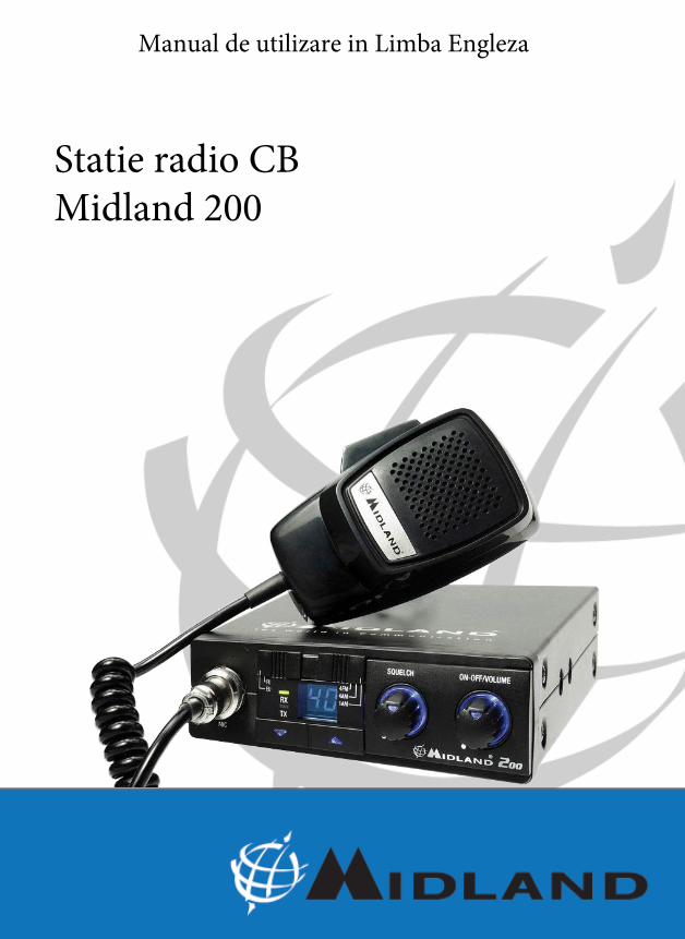
Statie radio CB Midland 200
Manual de utilizare in Limba Engleza
EN
GLI
SH
1
CONTENTS
Features ................................................................................................................pag. 2
Installation .............................................................................................................pag. 3
Replacing fuse .......................................................................................................pag. 4
Antenna system .....................................................................................................pag. 4
Mobile antennas ....................................................................................................pag. 4
Base station antenna .............................................................................................pag. 5
Using the transceiver .............................................................................................pag. 5
Transmission ..........................................................................................................pag. 6
Band selector..........................................................................................................pag. 6
Remote speaker operation ....................................................................................pag. 7
Technical specifications .........................................................................................pag. 8
2
EN
GLI
SH
2
FEATURES• Phase Locked Loop circuitry gives precise frequency control and stability over all 40 channels:
pinpoint channel tuning accuracy with separate scan up and down controls.• Ceramic filters give superior selectivity and freedom from adjacent channel interference.• Blue Led channel indicator clearly shows which channel is activated.• Red Led (TX) and Green Led (RX) show the operative modality:
TX= transmission; RX=reception.• Hysteresis-type Squelch circuit automatically compensates for signal fading to eliminate signal
“chopping” during message reception.• Extremely sensitive.• Condenser type plug-in communications microphone provides superior transmission.• The band selector allows the immediate switching from PL to EU band• Jacks for external speaker let you hook up other speaker systems.• Works with negative ground 12 - 13.8 V DC.
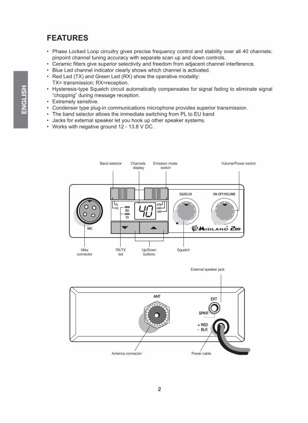
EXTANT
SPKR
+-
REDBLK
Presa altoparlante esterno
Connettore antenna Cavo alimentazione
Band selector Emission mode switch
External speaker jack
EXTANT
SPKR
+-
REDBLK
EXTANT
SPKR
+-
REDBLK
EXTANT
SPKR
+-
REDBLK
RX/TX led
Mikeconnector
Up/Down buttons
Squelch
RX
TX
SQUELCH ON-OFF/VOLUME
MIC
Channels display
Volume/Power switchCommutatore banda
Commutatoremodalità di emissione
LedRX/TX
Presa microfono
Tasti Up/Down(cambio canale)
Squelch
RX
TX
SQUELCH ON-OFF/VOLUME
MIC
Display canali
Accensione/volume
EN
GLI
SH
3
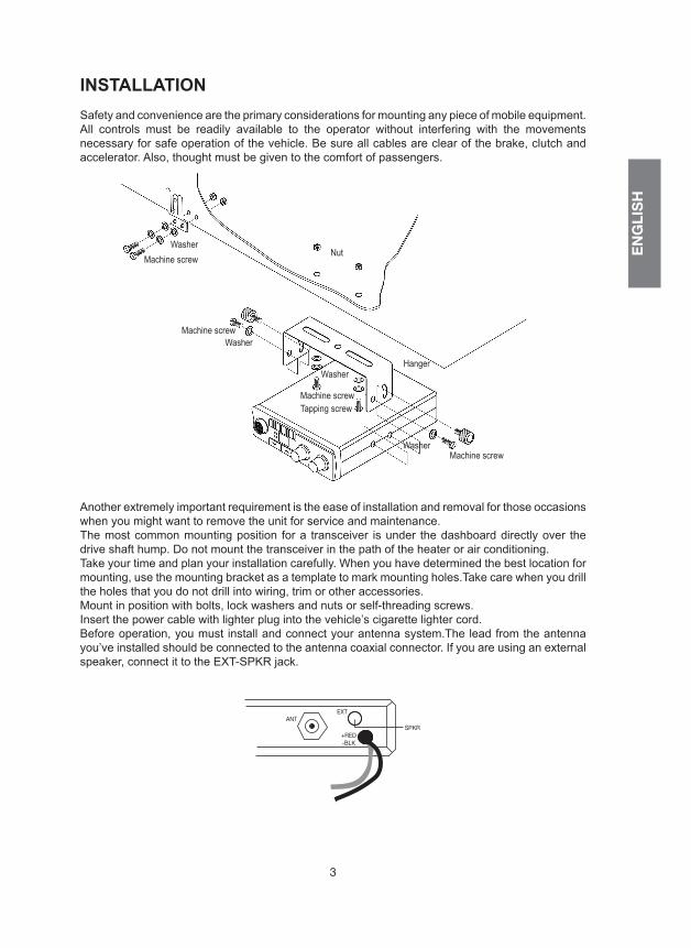
INSTALLATIONSafety and convenience are the primary considerations for mounting any piece of mobile equipment. All controls must be readily available to the operator without interfering with the movements necessary for safe operation of the vehicle. Be sure all cables are clear of the brake, clutch and accelerator. Also, thought must be given to the comfort of passengers.
Another extremely important requirement is the ease of installation and removal for those occasions when you might want to remove the unit for service and maintenance.The most common mounting position for a transceiver is under the dashboard directly over the drive shaft hump. Do not mount the transceiver in the path of the heater or air conditioning. Take your time and plan your installation carefully. When you have determined the best location for mounting, use the mounting bracket as a template to mark mounting holes.Take care when you drill the holes that you do not drill into wiring, trim or other accessories.Mount in position with bolts, lock washers and nuts or self-threading screws.Insert the power cable with lighter plug into the vehicle’s cigarette lighter cord. Before operation, you must install and connect your antenna system.The lead from the antenna you’ve installed should be connected to the antenna coaxial connector. If you are using an external speaker, connect it to the EXT-SPKR jack.
ANTEXT
SPKR+RED-BLK
WasherMachine screw
Machine screwWasher
Washer
Machine screw
Nut
Hanger
WasherMachine screw
Tapping screw
4
EN
GLI
SH
4
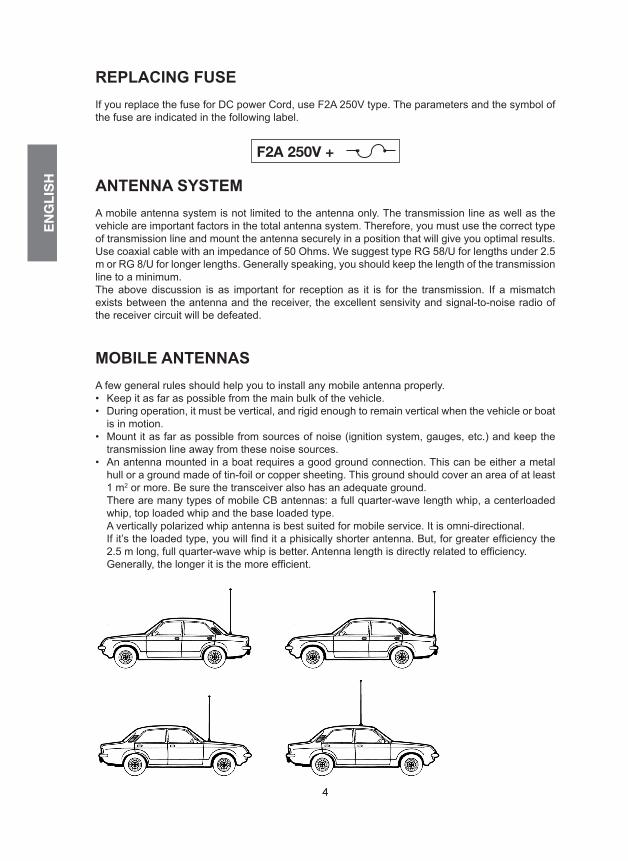
REPLACING FUSEIf you replace the fuse for DC power Cord, use F2A 250V type. The parameters and the symbol of the fuse are indicated in the following label.
ANTENNA SYSTEMA mobile antenna system is not limited to the antenna only. The transmission line as well as the vehicle are important factors in the total antenna system. Therefore, you must use the correct type of transmission line and mount the antenna securely in a position that will give you optimal results. Use coaxial cable with an impedance of 50 Ohms. We suggest type RG 58/U for lengths under 2.5 m or RG 8/U for longer lengths. Generally speaking, you should keep the length of the transmission line to a minimum.The above discussion is as important for reception as it is for the transmission. If a mismatch exists between the antenna and the receiver, the excellent sensivity and signal-to-noise radio of the receiver circuit will be defeated.
MOBILE ANTENNASA few general rules should help you to install any mobile antenna properly.• Keep it as far as possible from the main bulk of the vehicle.• During operation, it must be vertical, and rigid enough to remain vertical when the vehicle or boat
is in motion.• Mount it as far as possible from sources of noise (ignition system, gauges, etc.) and keep the
transmission line away from these noise sources.• An antenna mounted in a boat requires a good ground connection. This can be either a metal
hull or a ground made of tin-foil or copper sheeting. This ground should cover an area of at least1 m2 or more. Be sure the transceiver also has an adequate ground.There are many types of mobile CB antennas: a full quarter-wave length whip, a centerloadedwhip, top loaded whip and the base loaded type.A vertically polarized whip antenna is best suited for mobile service. It is omni-directional.If it’s the loaded type, you will find it a phisically shorter antenna. But, for greater efficiency the2.5 m long, full quarter-wave whip is better. Antenna length is directly related to efficiency.Generally, the longer it is the more efficient.
F2A 250V +
EN
GLI
SH
5
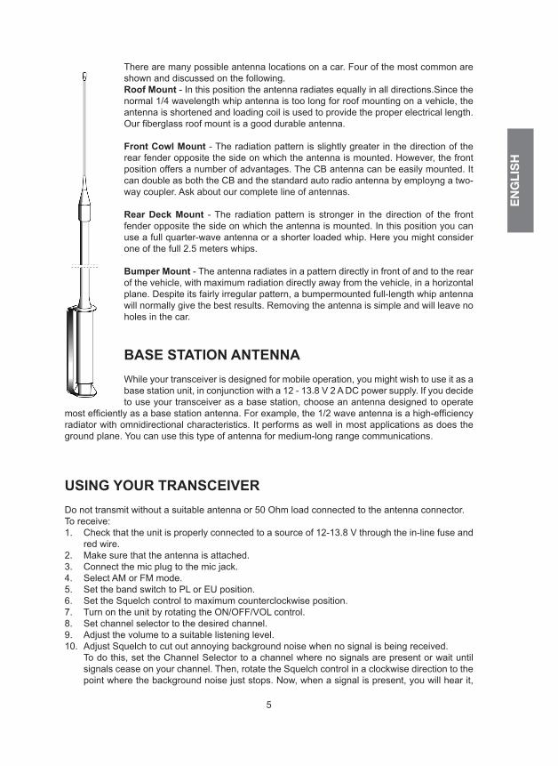
There are many possible antenna locations on a car. Four of the most common are shown and discussed on the following.Roof Mount - In this position the antenna radiates equally in all directions.Since the normal 1/4 wavelength whip antenna is too long for roof mounting on a vehicle, the antenna is shortened and loading coil is used to provide the proper electrical length. Our fiberglass roof mount is a good durable antenna.
Front Cowl Mount - The radiation pattern is slightly greater in the direction of the rear fender opposite the side on which the antenna is mounted. However, the front position offers a number of advantages. The CB antenna can be easily mounted. It can double as both the CB and the standard auto radio antenna by employng a two-way coupler. Ask about our complete line of antennas.
Rear Deck Mount - The radiation pattern is stronger in the direction of the front fender opposite the side on which the antenna is mounted. In this position you can use a full quarter-wave antenna or a shorter loaded whip. Here you might consider one of the full 2.5 meters whips.
Bumper Mount - The antenna radiates in a pattern directly in front of and to the rear of the vehicle, with maximum radiation directly away from the vehicle, in a horizontal plane. Despite its fairly irregular pattern, a bumpermounted full-length whip antenna will normally give the best results. Removing the antenna is simple and will leave no holes in the car.
BASE STATION ANTENNAWhile your transceiver is designed for mobile operation, you might wish to use it as a base station unit, in conjunction with a 12 - 13.8 V 2 A DC power supply. If you decide to use your transceiver as a base station, choose an antenna designed to operate
most efficiently as a base station antenna. For example, the 1/2 wave antenna is a high-efficiency radiator with omnidirectional characteristics. It performs as well in most applications as does the ground plane. You can use this type of antenna for medium-long range communications.
USING YOUR TRANSCEIVERDo not transmit without a suitable antenna or 50 Ohm load connected to the antenna connector.To receive:1. Check that the unit is properly connected to a source of 12-13.8 V through the in-line fuse and
red wire.2. Make sure that the antenna is attached.3. Connect the mic plug to the mic jack.4. Select AM or FM mode.5. Set the band switch to PL or EU position.6. Set the Squelch control to maximum counterclockwise position.7. Turn on the unit by rotating the ON/OFF/VOL control.8. Set channel selector to the desired channel.9. Adjust the volume to a suitable listening level.10. Adjust Squelch to cut out annoying background noise when no signal is being received.
To do this, set the Channel Selector to a channel where no signals are present or wait untilsignals cease on your channel. Then, rotate the Squelch control in a clockwise direction to thepoint where the background noise just stops. Now, when a signal is present, you will hear it,

6
EN
GLI
SH
6
but will not be disturbed by noise on the channel between signals.When properly set, the Squelch keeps the receiver “dead” until a signal comes in on that channel. However, do not set the Squelch too high, otherwise weak signals will not be able to open the Squelch circuit. To receive very weak signals, it is best to leave Squelch set to the mi-nimum position by rotating the control maximum counterclockwise. The Squelch circuit in your Transceiver is an advanced design. It uses an operational amp IC to accomplish a hysteresis action. The result is that when you set the Squelch for a precise signal level, if that signal level increases or decreases in strength, the Squelch circuit will follow this change. With conventio-nal Squelch circuit, often a signal which changes strength get “chopped” by the Squelch circuit and you lose a portion of the message.With a hysteresis Squelch, you get it all.
TRANSMISSIONThe emission switch (4W FM - 4W AM - 1W AM) allows you to select the power and modulation. once you set such selections, follow these steps:1. Select the desired channel.2. Press the push-to talk button on the microphone and hold it an angle about 5-7 cm from your
mouth and speak in a normal voice.3. To receive, release the push-to-talk button.Be sure the mic plug is firmly connected to the jack.
NOTE: shouting into the mic will not increase your power or signal. An internal circuit automatically sets the mic signal for maximum modulation, so speaking loudly will give no advantage.
BAND SELECTORThe PL/EU selector allows you to switch to PL (Polish) or EU (Europe) bands.PL (Poland): 40 CH AM/FM 4W; 26.960-27.400MHzEU (Europe): 40 CH FM 4W/40 CH AM 1W; 26.965-27.405MHz
FREQUENCY BAND CHART
Frequency Frequency band Band selector Emission mode switch
I Fx 26,965 - 27,405 MHz 40CH AM/FM 4W EU 4W FM / 4W AME Fx 26,965 - 27,405 MHz 40CH AM/FM 4W EU 4W FM / 4W AM
EC Fx 26,965 - 27,405 MHz 40CH FM 4W EU 4W FMEU Fx 26,965 - 27,405 MHz 40CH FM 4W 40CH AM 1W EU 4W FM / 1W AMF Fx 26,965 - 27,405 MHz 40CH FM 4W 40CH AM 1W EU 4W FM / 1W AM
PL Fx 26,960 - 27,400 MHz 40CH AM/FM 4W PL 4W FM / 4W AM
EN
GLI
SH
7
EXTANT
SPKR
+-
REDBLK
Presa altoparlante esterno
Connettore antenna Cavo alimentazione
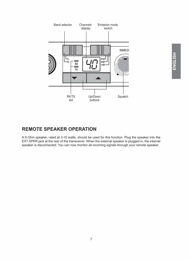
Band selector Emission mode switch
External speaker jack
EXTANT
SPKR
+-
REDBLK
EXTANT
SPKR
+-
REDBLK
EXTANT
SPKR
+-
REDBLK
RX/TX led
Mikeconnector
Up/Down buttons
Squelch
RX
TX
SQUELCH ON-OFF/VOLUME
MIC
Channels display
Volume/Power switchCommutatore banda
Commutatoremodalità di emissione
LedRX/TX
Presa microfono
Tasti Up/Down(cambio canale)
Squelch
RX
TX
SQUELCH ON-OFF/VOLUME
MIC
Display canali
Accensione/volume
REMOTE SPEAKER OPERATIONA 8 Ohm speaker, rated at 3-10 watts, should be used for this function. Plug the speaker into the EXT SPKR jack at the rear of the transceiver. When the external speaker is plugged in, the internal speaker is disconnected. You can now monitor all incoming signals through your remote speaker.
8
EN
GLI
SH
8
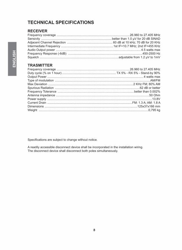
TECHNICAL SPECIFICATIONS
RECEIVERFrequency coverage .....................................................................................26.960 to 27.405 MHzSensivity ..................................................................................better than 1.0 μV for 20 dB SINADAdjacent Channel Rejection ..................................................... 60 dB at 10 kHz; 70 dB for 20 KHzIntermediate Frequency .............................................................1st IF=10.7 MHz; 2nd IF=455 KHzAudio Output power ................................................................................................... 4.5 watts maxFrequency Response (-6dB) .......................................................................................450-2500 HzSquelch ............................................................................................adjustable from 1.2 μV to 1mV
TRASMITTERFrequency coverage .....................................................................................26.960 to 27.405 MHzDuty cycle (% on 1 hour) ............................................................... TX 5% - RX 5% - Stand-by 90%Output Power ................................................................................................................ 4 watts maxType of modulation ...............................................................................................................AM/FMMax Deviation ...................................................................................................2 KHz FM; 80% AMSpurious Radiation ...................................................................................................62 dB or betterFrequency Tolerance .........................................................................................better than 0.002%Antenna impedance .............................................................................................................50 OhmPower supply ..........................................................................................................................13.8VCurrent Drain ...................................................................................................FM: 1.3 A; AM: 1.8 ADimensions ............................................................................................................125x37x166 mmWeight ................................................................................................................................0,795 kg
Specifications are subject to change without notice.
A readily accessible disconnect device shall be incorporated in the installation wiring.The disconnect device shall disconnect both poles simultaneously.