Embed Size (px)
Citation preview

Middle East Technical UniversityMiddle East Technical UniversityAeroAerospacespace Engineering Department Engineering Department
STEERING LAWS FOR CONTROL MOMENT GYROSCOPE SYSTEMS
USED IN SPACECRAFTS ATTITUDE CONTROL
by by Emre YAVUZOĞLUEmre YAVUZOĞLU
Supervisor: Supervisor: Assoc. Prof. Dr. Assoc. Prof. Dr. Ozan TEKİNALPOzan TEKİNALP

Outline• Objectives
• Properties of SGCMGs
• Overview of Steering Laws
• Simulation Work I
• CMG based ACS Model
• Simulation Work II
• Conclusion

• Investigation of the kinematic properties of SGCMGs ( + singularity problem)
• Steering laws:– Existing steering laws
– Development of new steering laws
– Comparison of steering laws through simulations
Objectives

• Momentum exchange device
• A SGCMG consists of– Flywheel
(spinning at a constant rate)– Gimbal motor
(to change the direction of h)
SGCMGs

The output torque is:
τ h δ h
τ h δ h
(Torque amplification)
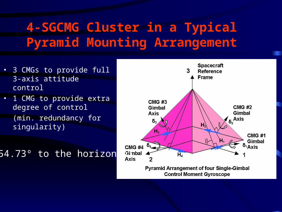
4-SGCMG Cluster in a Typical Pyramid Mounting Arrangement
• 3 CMGs to provide full 3-axis attitude control
• 1 CMG to provide extra degree of control
(min. redundancy for singularity)
β=54.73º to the horizontal
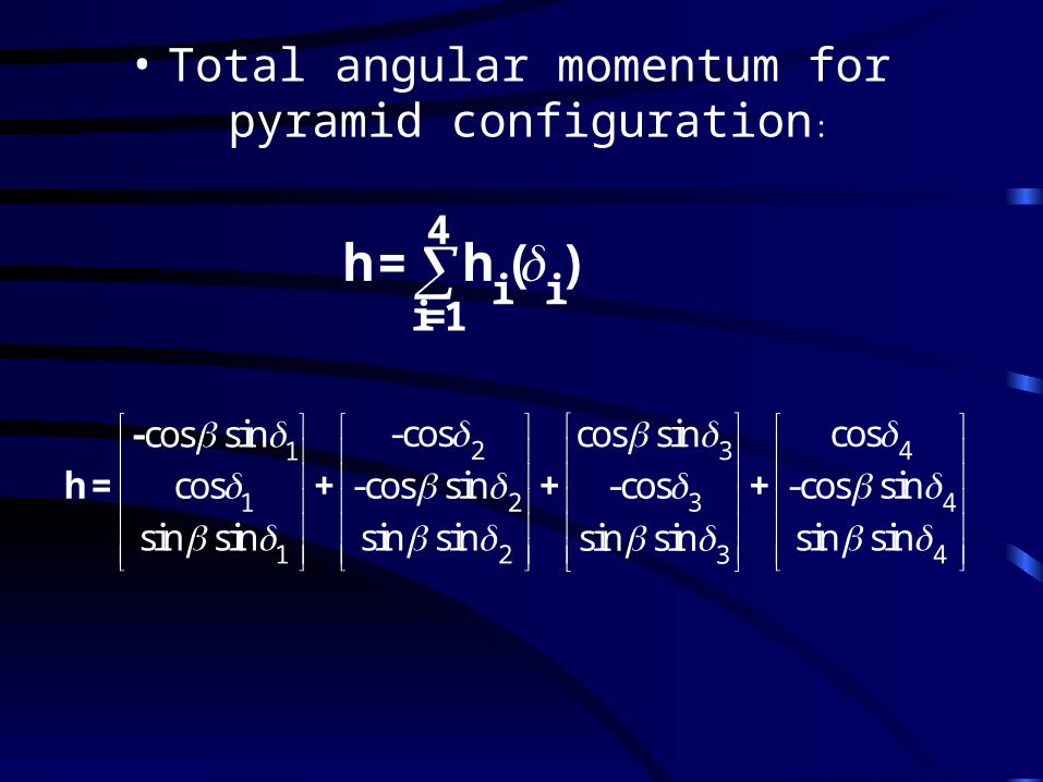
• Total angular momentum for pyramid configuration:
4
i ii=1
h= h ( )
2 431
1 2 3 4
1 2 43
-cos coscos sincos sin
cos -cos sin -cos -cos sin
sin sin sin sin sin sinsin sin
-
h = + + +

•Total output torque (time rate of change of total h)
1 2 3 4
1 2 3 4
1 2 3 4
cos cos sin cos cos sin
sin cos cos sin cos cos
sin cos sin cos sin cos sin cos
hJ(δ)
δ
h=J(δ)δ
However, in ACS part we need to determine gimbal rate, that provides the required torque. Thus, we need an inversion of torque equation:
where instantaneous system Jacobian matrix:
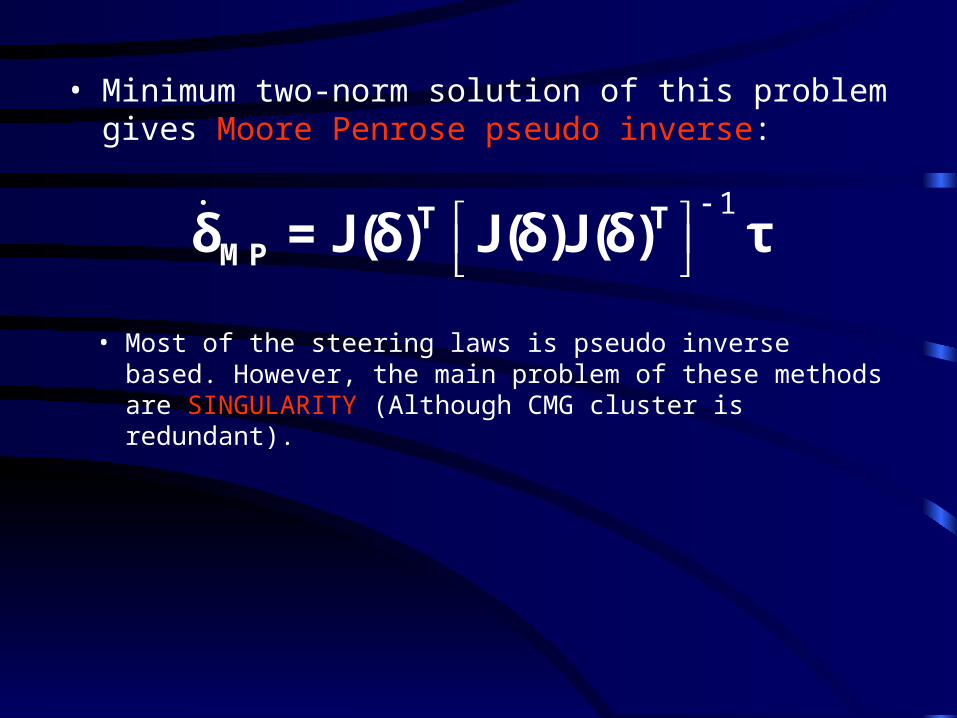
• Minimum two-norm solution of this problem gives Moore Penrose pseudo inverse:
1
T TMPδ = J(δ) J(δ)J(δ) τ
• Most of the steering laws is pseudo inverse based. However, the main problem of these methods are SINGULARITY (Although CMG cluster is redundant).

What is Singularity?
• Mathematically; When J loses rank (rank:2), (JJT)-
1 undefined.• Physically; all output torque vectors remain on the
same plane (rank:2). No output torque can be produced along direction, s, normal to this plane. (s: singularity direction). Three axis controllability is lost.
TJ s 0

Singularity Measure
det( )m TJ(δ)J(δ)
(System is how much close to the singularity)
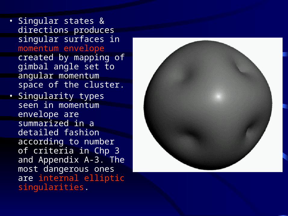
• Singular states & directions produces singular surfaces in momentum envelope created by mapping of gimbal angle set to angular momentum space of the cluster.
• Singularity types seen in momentum envelope are summarized in a detailed fashion according to number of criteria in Chp 3 and Appendix A-3. The most dangerous ones are internal elliptic singularities.

Overview of Steering Laws
2. SR Inverse
3. GSR Inverse
4. IG Method
1
T TMPδ = J(δ) J(δ)J(δ) τ
1. MP INVERSE (high possibility of encountering singular states)
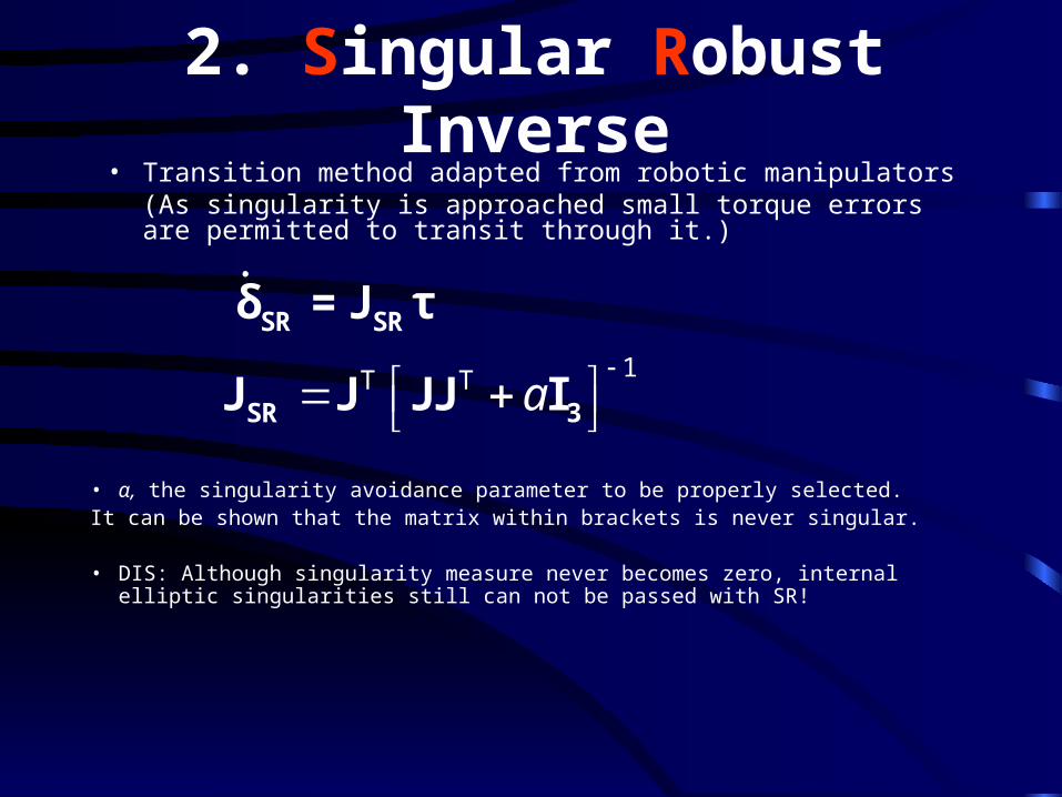
2. Singular Robust Inverse• Transition method adapted from robotic manipulators
(As singularity is approached small torque errors are permitted to transit through it.)
SR SRδ = J τ1T T a
SR 3J J JJ I
• α, the singularity avoidance parameter to be properly selected. It can be shown that the matrix within brackets is never singular.
• DIS: Although singularity measure never becomes zero, internal elliptic singularities still can not be passed with SR!

3. Generalized Singular Robust Inverse• Modified version of SR inverse
As singularity is approached, deliberate deterministic dither signals of increasing amplitude are used to get out of singularity quickly:
T T -1G-SR [ ] δ J JJ E τ
3 2
3 1
2 1
1
= 1 0
1
E 0.01sin(0.5 )i it
0.01exp( 10 )m where
• DIS: Not suitable for precision tracking missions

4. Inverse Gain • Previous particular solutions can be combined with
homogenous solution of torque equation to avoid singularities (=null motion):
particular homogenousδ = δ + δ
31 2
1 2 3 4
hh hn C ,C ,C ,C
δ δ δ
homogenous c.δ n
6
6
, 1
, 1
m mc
m m
• DIS: Null rates may become extremely high, even though system is away from singularity.

New Steering Logic:Unified Steering Law
• Derived solving the following minimization problem:
err err err err
1
2T T
δmin δ Qδ τ Rτ
• Starting aim in the development was to find gimbal rates both satisfying torque commanded and, driving the gimbals to desired nonsingular configurations, spontaneously.
err desiredδ δ - δerrτ = Jδ - τ

Resulted gimbal rate equation:
T Tq q -1
USL 4 desiredδ = I + J J δ + J τ
• Through simulations we have observed that selection of desired gimbal rate, and blending coefficient, q, are the key points in the utilization of the method. According to this selection, 2 approaches are proposed:
1. Preplanned Steering2. Online Steering
1. Preplanned Steering
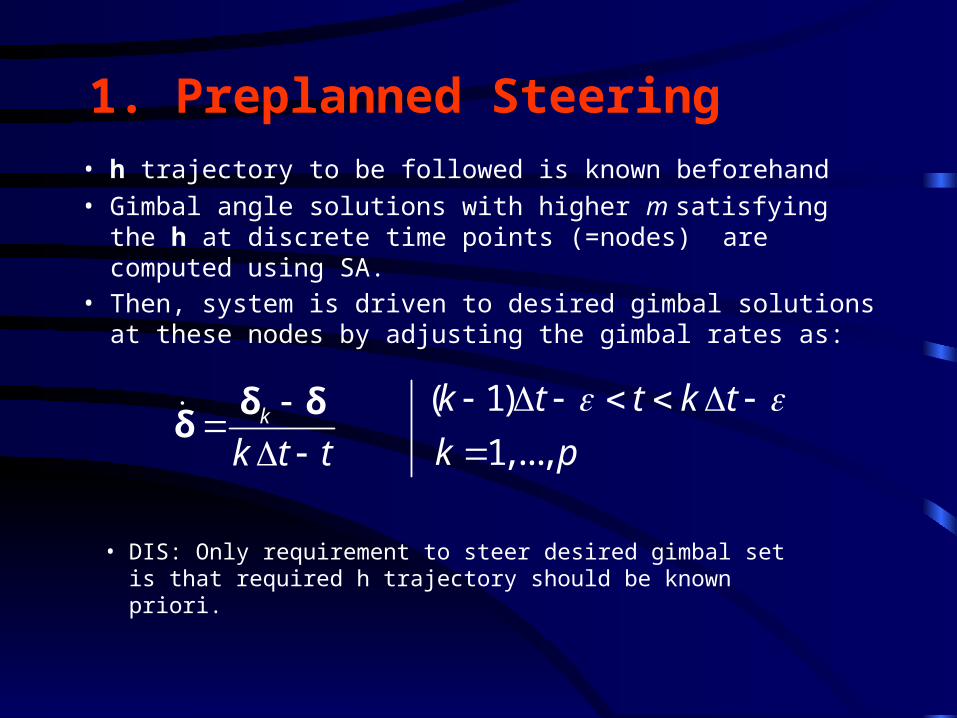
• h trajectory to be followed is known beforehand
• Gimbal angle solutions with higher m satisfying the h at discrete time points (=nodes) are computed using SA.
• Then, system is driven to desired gimbal solutions at these nodes by adjusting the gimbal rates as:
• DIS: Only requirement to steer desired gimbal set is that required h trajectory should be known priori.
( 1)
1,...,k
k t t k t
k pk t t
δ δ
δ

2. Online Steering Approaches
For selection of desired gimbal rate in USL Eqn.:
a. Homogenous gimbal rates found by IG
b. Arbitrary constant vector
c. Intelligently selected constant vector
d. Dynamic vector with randomly changing elements
(White Noise)

Simulations I• Constant torque study
0 0.5 1 1.5 2 2.5-0.2
0
0.2
0.4
0.6
0.8
1
Torque Realized
t (s)
T (
Nm
)
TxTyTz
0 ,0 ,0 ,0T oδ [1.155,0,0]T
des τ
0 0.5 1 1.5 2 2.5-0.5
0
0.5
1
1.5
2
2.5
3
Angular Momentum Trajectory
t (s)
h (
Nm
.s)
hxhyhz
Ideal Profiles
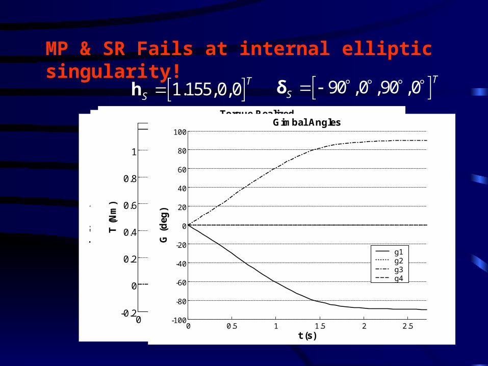
MP & SR Fails at internal elliptic singularity!
0 0.5 1 1.5 2 2.5-0.5
0
0.5
1
1.5Angular Momentum Trajectory
t (s)
h (
Nm
.s)
hxhyhz
0 0.5 1 1.5 2 2.50
0.2
0.4
0.6
0.8
1
1.2
Singularity Measure
t (s)
m
0 0.5 1 1.5 2 2.5-0.2
0
0.2
0.4
0.6
0.8
1
Torque Realized
t (s)
T (
Nm
)
TxTyTz
0 0.5 1 1.5 2 2.5-100
-80
-60
-40
-20
0
20
40
60
80
100Gimbal Angles
t (s)
G (
deg
)
g1g2g3g4
90 ,0 ,90 ,0T
S δ 1.155,0,0T
S h
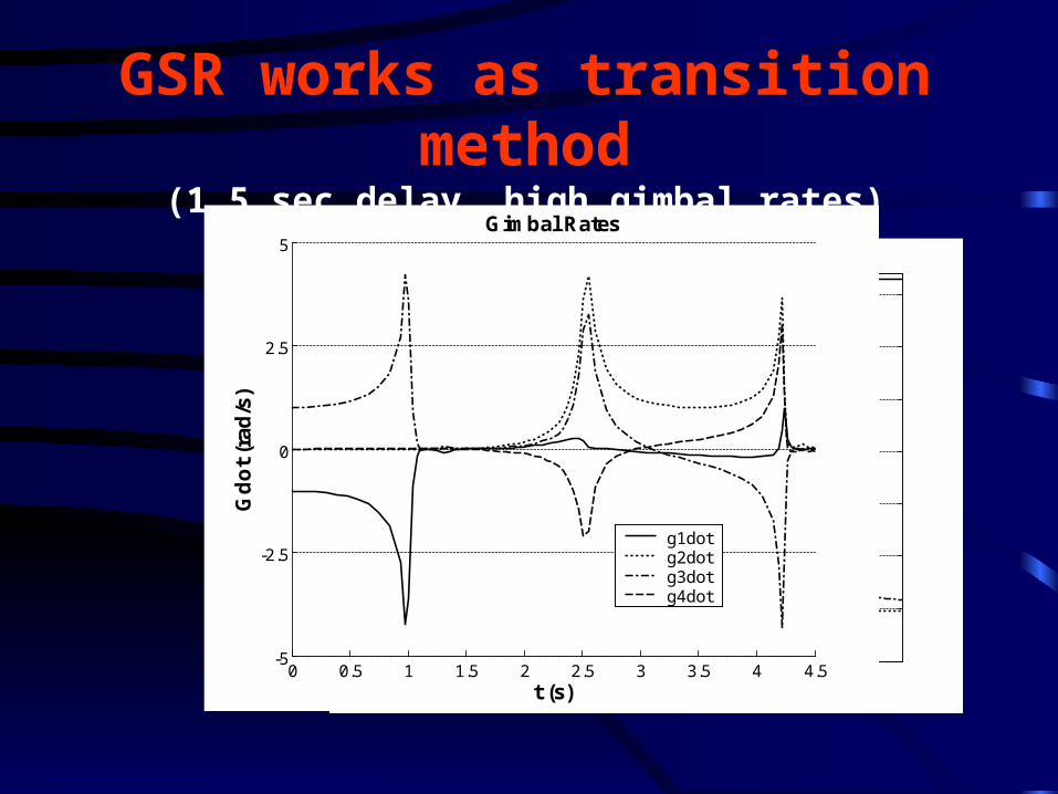
GSR works as transition method(1.5 sec delay, high gimbal rates)
0 1 2 3 4-0.2
0
0.2
0.4
0.6
0.8
1
Torque Realized
t (s)
T (
Nm
)
TxTyTz
0 0.5 1 1.5 2 2.5 3 3.5 4 4.50
0.2
0.4
0.6
0.8
1
1.2
1.4
1.6
1.8
2Singularity Measure
t (s)
m
0 1 2 3 4-0.5
0
0.5
1
1.5
2
2.5
3
Angular Momentum Trajectory
t (s)
h (
Nm
.s)
hxhyhz
0 0.5 1 1.5 2 2.5 3 3.5 4 4.5-5
-2.5
0
2.5
5Gimbal Rates
t (s)
Gd
ot
(rad
/s)
g1dotg2dotg3dotg4dot
USL Preplanned
0 0.5 1 1.5 2 2.5-0.2
0
0.2
0.4
0.6
0.8
1
Torque Realized
t (s)
T (
Nm
)
TxTyTz
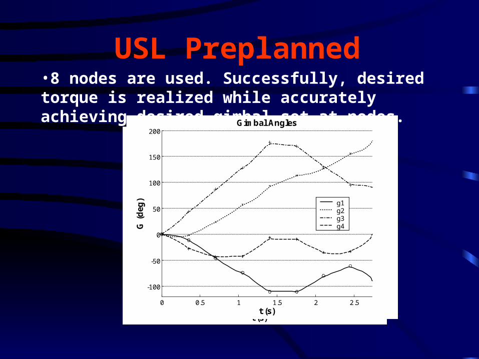
•8 nodes are used. Successfully, desired torque is realized while accurately achieving desired gimbal set at nodes.
0 0.5 1 1.5 2 2.5
-100
-50
0
50
100
150
200Gimbal Angles
t (s)
G (
deg
) g1g2g3g4

USL Online using Null vector
0 0.5 1 1.5 2 2.5-0.2
0
0.2
0.4
0.6
0.8
1
Torque Realized
t (s)
T (
Nm
)
TxTyTz
0 0.5 1 1.5 2 2.5-0.2
0
0.2
0.4
0.6
0.8
1
Torque Realized
t (s)
T (
Nm
)
TxTyTz

USL Online Using Constant Vector (with dynamically adjusted blending coefficient q=0.5exp(-10m))
0 0.5 1 1.5 2 2.5 3 3.5-0.2
0
0.2
0.4
0.6
0.8
1
Torque Realized
t (s)
T (
Nm
)
TxTyTz
0 0.5 1 1.5 2 2.5-0.2
0
0.2
0.4
0.6
0.8
1
Torque Realized
t (s)
T (
Nm
)
TxTyTz
•Steering w. arbitrary vector [0,1,0,0]•Steering w. intelligently selected vector•Steering w. white noise
0 1 2 3 4-0.2
0
0.2
0.4
0.6
0.8
1
Torque Realized
t (s)
T (
Nm
)
TxTyTz

USL Preplanned Corner maneuver
0 0.5 1 1.5-0.8
-0.6
-0.4
-0.2
0
0.2
0.4
0.6
0.8
1Torque Realized
t (s)
T (
Nm
)
TxTyTz
Repeatability maneuver
Cyclic Disturbance
0 0.5 1 1.5 2 2.5-0.2
0
0.2
0.4
0.6
0.8
1
1.2
Torque Realized
t (s)
T (
Nm
)
TxTyTz
0 0.5 1 1.5 2 2.5 3 3.5 4 4.5
-100
-50
0
50
100
150
200Gimbal Angles
t (s)
G (
deg
)
g1g2g3g4gdes1gdes2gdes3gdes4
T T1.15 0 0 0.115 [1 1 1] sin(2 )tdesiredτ =desired
1[1,1,0] , t<0.8344
21
[1, 1,0] , t>0.8344 2
T
T
τ

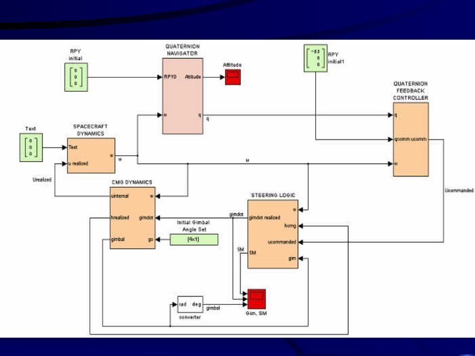
CMG based ACS ModelThree main parts to be considered:
1. Spacecraft Dynamics
2. Quaternion Based Feedback Controller
3. CMG Steering Law
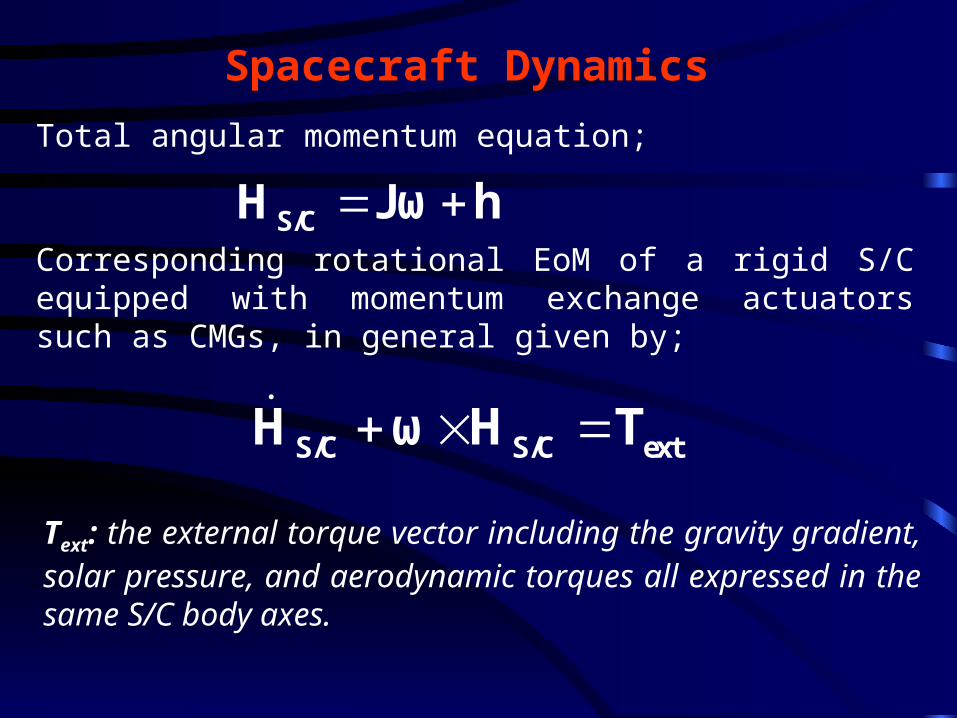
Spacecraft Dynamics
Total angular momentum equation;
Corresponding rotational EoM of a rigid S/C equipped with momentum exchange actuators such as CMGs, in general given by;
Text: the external torque vector including the gravity gradient, solar pressure, and aerodynamic torques all expressed in the same S/C body axes.
S/C S/C extH ω H T
S/CH Jω h

Combining these 2 equations, we simply obtain;
u: Internal control torque input generated by CMG and transferred to S/C
Rewriting equation in two parts;
By using last two equations, and combining them with S/C kinematics equations (such as quaternions), an ACS can be designed. Assuming S/C control torque input is known, the desired CMG momentum rate is selected as:
+ u- u extJω h ω Jω h T
extJω ω Jω T u
h ω h u
h ω h u
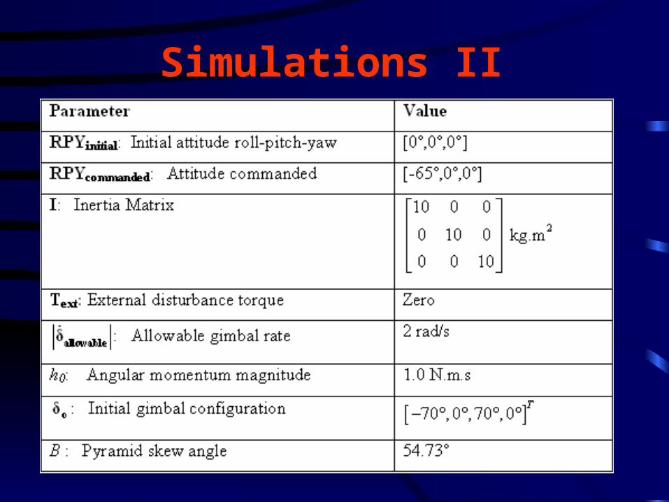
Simulations II

USL Preplanned Results
0 50 100 150 200 250 300-0.2
0
0.2
0.4
0.6
0.8
1
1.2
1.4
Angular Momentum Trajectory
t (s)
h (
Nm
.s)
hxhyhz
0 50 100 150 200 250 300-150
-100
-50
0
50
100Gimbal Angles
t (s)
G (
deg
)
g1g2g3g4gdes1gdes2gdes3gdes4
Desired h profile from ideal systemGimbal profiles obtained with USL
0 50 100 150 200 250 300-70
-60
-50
-40
-30
-20
-10
0
10Spacecraft Attitude Profile
t (s)
Ro
ll-P
itch
-Yaw
(
deg
.)
RollPitchYaw
Attitude profile obtained with USL

USL Online Results
0 50 100 150 200 250-70
-60
-50
-40
-30
-20
-10
0
10Spacecraft Attitude Profile
t (s)
Ro
ll-P
itch
-Yaw
(
deg
.)
RollPitchYaw
0 50 100 150 200 2500
0.2
0.4
0.6
0.8
1
1.2
Singularity Measure
t (s)
m
0 50 100 150 200 250-250
-200
-150
-100
-50
0
50
100
150
200
250Gimbal Angles
t (s)
G (
deg
) g1g2g3g4
• Although simulation is started this time at internal elliptic singularity (i.e. [90, 0, -90, 0]deg), USL online method effectively takes the system away from singularity rapidly, and maneuver is completed on time!
• Arbitrarily selected vector [0,1,0,0] is used as desired gimbal rate with dynamically adjusted blending coefficient.
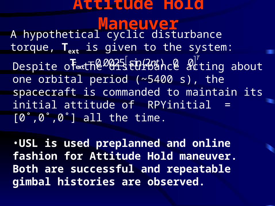
Attitude Hold Maneuver
0.0025 sin(2 ) 0 0T
ntextT
A hypothetical cyclic disturbance torque, Text is given to the system:
Despite of the disturbance acting about one orbital period (~5400 s), the spacecraft is commanded to maintain its initial attitude of RPYinitial = [0˚,0˚,0˚] all the time.
•USL is used preplanned and online fashion for Attitude Hold maneuver. Both are successful and repeatable gimbal histories are observed.
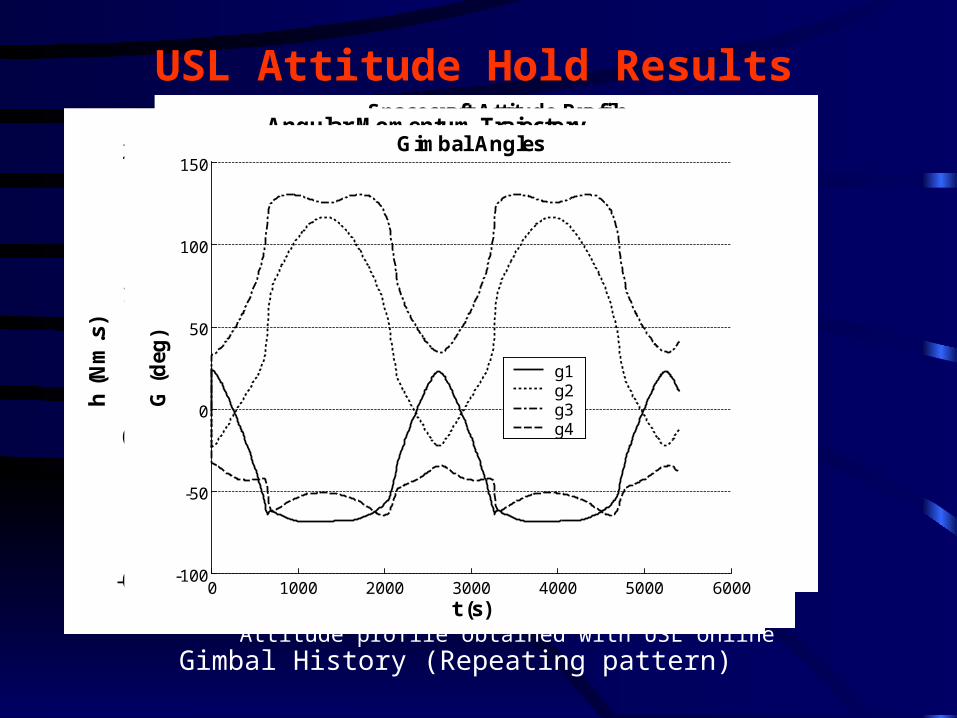
USL Attitude Hold Results
0 1000 2000 3000 4000 5000 6000-0.06
-0.04
-0.02
0
0.02
0.04
0.06Spacecraft Attitude Profile
t (s)
Ro
ll-P
itch
-Yaw
(
deg
.)RollPitchYaw
0 1000 2000 3000 4000 5000 6000-0.5
0
0.5
1
1.5
2
2.5Angular Momentum Trajectory
t (s)
h (
Nm
.s)
hxhyhz
Attitude profile obtained with USL online
0 1000 2000 3000 4000 5000 6000-100
-50
0
50
100
150Gimbal Angles
t (s)
G (
deg
)
g1g2g3g4
Gimbal History (Repeating pattern)
CONCLUSION
• A new original robust steering law is presented. The steering law combines desired gimbal rates with torque requirements in a weighted fashion.
• The law can be employed in a both preplanned and spontaneous fashion. The repeatability of the approach is demonstrated.
• Singularity is not a problem with this method. Through simulations, it is demonstrated that it can replace all existing steering laws.
• This method may also be adapted to robotic manipulators as a future work.

THANK YOU