Embed Size (px)
Citation preview

PARAMETRIC FOUNDATION & BOLT STUDY February 24, 20111
ITER MID ELM
FOUNDATION & BOLT LOADS STUDY
Parametric Stress Analysis
February 24, 2011

PARAMETRIC FOUNDATION & BOLT STUDY February 24, 2011
Objectives
• Determine All Loads & Moments for the Mid Elm– Summarize all loads at local coordinate systems at each foundation pad
– Repeat the evaluation for each of the three load steps (See PDR Update 12-2-10)
• Provide Tabular summaries of the Foundation loads for all three load cases.– First Load Step is Thermal Loads
– Second Load Step is combined Thermal + Lorentz Load Toward Reactor Foundation Wall
– Third Load Step is combined Thermal + Lorentz Load Toward Plasma
• Provide a hand calculation of the Poloidal Foundation stress
• Provide Tabular summaries of the loads on the Poloidal & Corner Brackets– Apply these loads to Sub-Models of the brackets with bolt details defined.
– Evaluate the Current Foundation Rail Stresses with all three load cases
– Evaluate the Bolt loads on these brackets with all three load cases
• Complete a Design of Experiments Optimization of the Poloidal Bracket Rail– Parametrically adjust the length of the foundation rail width
– Illustrate sensitivity charts and response envelopes of the bolts and rail stresses as a
function of these changes
– Identify several candidate designs that will minimize the rail stresses
• Evaluate the Corner Bracket Rails based on the current design
• Provide conclusions and recommendations

PARAMETRIC FOUNDATION & BOLT STUDY February 24, 2011
PDR -ASSUMPTIONS
• The interface between the MGO insulation and the Coil is assumed to be
bonded contact.
– Conservative since transverse Lorentz loads could cycle the coil in tension.
– Additional work to characterize and calibrate the load transfer is in process.
• A reference temperature of 100 C is applied to all materials.
– This accounts for displacements of the reactor to boundary interface.
• Error is small since thermal expansion coefficients are similar
– Future work will map boundary thermal displacements with APDL script
• Additional reactor displacement to be added based on 100 C temperatures.
• Bonded thermal Contact is assumed between the brackets and coils
although mechanical constraint is limited to end points
• Surrounding Blanket and reactor structures are uniform 100 C
• All analysis is steady state3

PARAMETRIC FOUNDATION & BOLT STUDY February 24, 2011
Allowables and Acceptance Criteria
100C 200C 100C 200C
Primary Stress (PM, PL, PB)
General Primary Membrane 1.0 K Sm 120 108 147 130
Local primary membrane 1.5 K Sm 180 162 220.5 195
Primary Membrane plus bending 1.5 K Sm 180 162 220.5 195
Secondary (Q) (ie thermal) 3.0 K Sm 360 324 441 390
CuCrZr-IG 316L(N)-IG
Metalic Structure Acceptance Criteria (SDC-IC Appendix D)
Temperature 100C 200C 100C 200C
Minimum Ultimate Tensile Strength, Su 359 323 458 425
Minimum Yield Strength, Sy 253 235 172 144
Design Stress Intensity Limit, Sm 120 108 147 130
108 97 137 128
Stress Limits (SDC -IC), MPa
CuCrZr-IG 316L(N)-IG
Stress Endurance Limit, Se (=30% Su)
ITER_D_3VY7G5 V1.2
Max Shear Strength = 147/2 = 73.5Mpa = 10,660 Psi

PARAMETRIC FOUNDATION & BOLT STUDY February 24, 2011
FOUNDATION LOAD ANALYSIS
The PDR version (12-2-10) of the MID ELM is used to evaluate the foundation loads
POLOIDAL BRACKETCORNER BRACKET
Rigid Foundation at all supports
Loads Calculated at the Interface to the reactor vessel
Symmetric Constraint
Symmetric Constraint
5

PARAMETRIC FOUNDATION & BOLT STUDY February 24, 2011
ELM LORENTZ LOAD VS POSITION
Applied Maximum Lorentz Loads For Stress Range Calculation
(LFT)
(BOT)
(RHT)(TRC) (BLC)
Critical Quadrant
SECTOR 5 FE MODEL LOADS in GLOBAL COORDINATES
Fx Fy Fz
ELM_MD_BOT 121,508 60,907 -32,429
ELM_MD_BLC 105,447 77,208 -41,265
ELM_MD_LFT 236,652 185,166 7,491
OPPOSITE DIRECTION LOADING
ELM_MD_BOT -121,508 -60,907 +32,429
ELM_MD_BLC -105,447 -77,208 +41,265
ELM_MD_LFT -236,652 -185,166 -7491
(BRC)
6

PARAMETRIC FOUNDATION & BOLT STUDY February 24, 2011
TOROIDAL BRACKET
Reaction Coordinate Systems
The Toroidal Bolt Reaction Load Coordinate Systems are Defined
+z
+Y
+x
Coordinate System #180
Coordinate System #181

PARAMETRIC FOUNDATION & BOLT STUDY February 24, 2011
Corner Bracket
Reaction Coordinate Systems
The Corner Bracket Bolt Reaction Load Coordinate Systems are Defined for the Bolt Pad and
on the Foundation
+z
+Y
+x
Lorentz Load
Mxx = 4,463 NM
Load step #3
Mxx = -850 NM
Load step #3
Coordinate System #182Coordinate System #183

PARAMETRIC FOUNDATION & BOLT STUDY February 24, 2011
Poloidal Bracket
Reaction Coordinate Systems
+z
+Y
+x
The Poloidal Bolt Reaction Load Coordinate Systems are Defined at the Bolt Pad and on
the Foundation
Coordinate System #184Coordinate System #185

PARAMETRIC FOUNDATION & BOLT STUDY February 24, 2011
Foundation Pad Loads
** All loads are on foundation, reaction loads would have a reversed sign Highest Load Areas

PARAMETRIC FOUNDATION & BOLT STUDY February 24, 2011
POLOIDAL RAIL
Current Design
11

PARAMETRIC FOUNDATION & BOLT STUDY February 24, 2011
POLOIDAL FOUNDATION
COMPLEX – BENDING / SHEAR
12
Note: My : references Mz in loads
-7,053 psi = -48.6 Mpa
See Slide 18 for FE
Comparison 39 Mpa – 53 Mpa
PARAMETRIC FOUNDATION & BOLT STUDY February 24, 201113
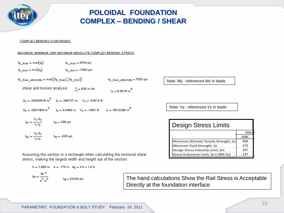
POLOIDAL FOUNDATION
COMPLEX – BENDING / SHEAR
Note: Vy : references Vz in loads
Note: My : references Mz in loads
Temperature 100C 200C 100C 200C
Minimum Ultimate Tensile Strength, Su 359 323 458 425
Minimum Yield Strength, Sy 253 235 172 144
Design Stress Intensity Limit, Sm 120 108 147 130
108 97 137 128
Stress Limits (SDC -IC), MPa
CuCrZr-IG 316L(N)-IG
Stress Endurance Limit, Se (=30% Su)
Temperature 100C 200C 100C 200C
Minimum Ultimate Tensile Strength, Su 359 323 458 425
Minimum Yield Strength, Sy 253 235 172 144
Design Stress Intensity Limit, Sm 120 108 147 130
108 97 137 128
Stress Limits (SDC -IC), MPa
CuCrZr-IG 316L(N)-IG
Stress Endurance Limit, Se (=30% Su)
Design Stress Limits
The hand calculations Show the Rail Stress is Acceptable
Directly at the foundation interface

PARAMETRIC FOUNDATION & BOLT STUDY February 24, 2011
Foundation/ Bolt Pad Analysis
14
POLOIDAL LOADS ON TOP OF COMB
CORNER LOADS ON TOP OF COMB

PARAMETRIC FOUNDATION & BOLT STUDY February 24, 2011
Poloidal Bolt / Foundation
Boundary Conditions
15
OUTSIDE INSIDE
BOLT1
BOLT3
BOLT4
* Preload is 182,000 N = 40,915 Lbf

PARAMETRIC FOUNDATION & BOLT STUDY February 24, 2011
Poloidal Bolt / Foundation
Thermal Stress
16
The Average Poloidal Foundation Thermal Stresses are in excess of the Material Limits –
primarily around the top section of the rail.
21e6 Pa = 3,045 psiTemperature 100C 200C 100C 200C
Minimum Ultimate Tensile Strength, Su 359 323 458 425
Minimum Yield Strength, Sy 253 235 172 144
Design Stress Intensity Limit, Sm 120 108 147 130
108 97 137 128
Stress Limits (SDC -IC), MPa
CuCrZr-IG 316L(N)-IG
Stress Endurance Limit, Se (=30% Su)
Temperature 100C 200C 100C 200C
Minimum Ultimate Tensile Strength, Su 359 323 458 425
Minimum Yield Strength, Sy 253 235 172 144
Design Stress Intensity Limit, Sm 120 108 147 130
108 97 137 128
Stress Limits (SDC -IC), MPa
CuCrZr-IG 316L(N)-IG
Stress Endurance Limit, Se (=30% Su)
8.5e6 Pa = 1,232 psi
STRESS INTENSITY NORMAL STRESS
133e6 Pa = 19,290 psi 169e6 Pa = 24,511 psi

PARAMETRIC FOUNDATION & BOLT STUDY February 24, 2011
Poloidal Bolt / Foundation
Thermal Stress + Lorentz Away From Plasma
17
The Average Poloidal Foundation Thermal +Lorentz Stresses are in excess of material
limits – primarily around the top section of the rail.
8e6 Pa = 1,160 psi Temperature 100C 200C 100C 200C
Minimum Ultimate Tensile Strength, Su 359 323 458 425
Minimum Yield Strength, Sy 253 235 172 144
Design Stress Intensity Limit, Sm 120 108 147 130
108 97 137 128
Stress Limits (SDC -IC), MPa
CuCrZr-IG 316L(N)-IG
Stress Endurance Limit, Se (=30% Su)
Temperature 100C 200C 100C 200C
Minimum Ultimate Tensile Strength, Su 359 323 458 425
Minimum Yield Strength, Sy 253 235 172 144
Design Stress Intensity Limit, Sm 120 108 147 130
108 97 137 128
Stress Limits (SDC -IC), MPa
CuCrZr-IG 316L(N)-IG
Stress Endurance Limit, Se (=30% Su)
56e6 Pa = 8,122 psi
STRESS INTENSITY NORMAL STRESS
189e6 Pa = 27,412 psi 260e6 Pa = 37,709 psi

PARAMETRIC FOUNDATION & BOLT STUDY February 24, 2011
Poloidal Bolt / Foundation
Thermal Stress + Lorentz Toward Plasma
18
The Average Poloidal Foundation Thermal +Lorentz Stresses are in excess of the stress
limits – primarily on the top section of the rails.
87e6 Pa = 12,618 psi
Temperature 100C 200C 100C 200C
Minimum Ultimate Tensile Strength, Su 359 323 458 425
Minimum Yield Strength, Sy 253 235 172 144
Design Stress Intensity Limit, Sm 120 108 147 130
108 97 137 128
Stress Limits (SDC -IC), MPa
CuCrZr-IG 316L(N)-IG
Stress Endurance Limit, Se (=30% Su)
Temperature 100C 200C 100C 200C
Minimum Ultimate Tensile Strength, Su 359 323 458 425
Minimum Yield Strength, Sy 253 235 172 144
Design Stress Intensity Limit, Sm 120 108 147 130
108 97 137 128
Stress Limits (SDC -IC), MPa
CuCrZr-IG 316L(N)-IG
Stress Endurance Limit, Se (=30% Su)
92e6 Pa = 13,343 psi
STRESS INTENSITY NORMAL STRESS
189e6 Pa = 27,412 psi 272e6 Pa = 39,450 psi

PARAMETRIC FOUNDATION & BOLT STUDY February 24, 2011
Normal Bolt Stress
19
Thermal + Lorentz
Toward Plasma
Thermal + Lorentz
Away From Plasma
210,000 N = 47,209 Lbf
172,000 N = 38,667 Lbf
The Load on Bolts 2 and 3 has excessive variation (8,542 Lbf) and will require a higher
preload or more bolts –The clamping force is not sufficient
Preload = 182,000 N = 40,915 Lbf

PARAMETRIC FOUNDATION & BOLT STUDY February 24, 2011
Poloidal Foundation
Parametric Study
20
OBJECTIVES:
1.) Use Load Step #3 (Lorentz Loads Toward Plasma) + Bolt Preloading
2.) Adjust the foundation width parameters and determine the impact on:
a.) The bolt working loads
b.) The foundation interface stress
c.) The rail & Attachment Stresses
3.) Make a recommendation based on these trends to assure an adequate design

PARAMETRIC FOUNDATION & BOLT STUDY February 24, 2011
Geometric Parameters
21
Smallest Option Evaluated Intermediate Option Evaluated
Largest Option EvaluatedInside Rail Dimension
0.0 to 15.5 mm
Outside Rail Dimension
55.0 to 65 mm

PARAMETRIC FOUNDATION & BOLT STUDY February 24, 2011
Sensitivity Charts for Bolt Loading
22
Similar Sensitivity on Bolt 4 and Bolt 3 for both rails
Bolt 1 and Bolt 2 are most influenced by the Inside Rail Length
Inside Rail
Outside Rail
Bolt 1Bolt 2
Bolt 3Bolt 4
Local Sensitivity Chart is based on Outside Rail 60 mm & Inside Rail = 8 mm; Preload = 2.184e5 N

PARAMETRIC FOUNDATION & BOLT STUDY February 24, 2011
Foundation Stress Sensitivity for Rail Parameter
Changes
23
Out Equiv Stress Inside Equiv StressOutside Stress
IntensityInside Stress
Intensity
Inside Rail
Outside Rail
The Inside Rail Dimension has the Largest Impact on the Foundation Stresses
Reduce foundation stress by changing inside rail dimensions
Local Sensitivity Chart is based on Outside Rail 60 mm & Inside Rail = 8 mm; Preload = 2.184e5 N

PARAMETRIC FOUNDATION & BOLT STUDY February 24, 2011
Stress Minimum Value
24
The Rail Dimensions Required to Minimize the Foundation Stress
Outside Rail of 60 mm and inside Rail 10 mm
** Table assumes a bolt preload of 218,400 N (49,098 Lbf) and applied Lorentz load toward plasma

PARAMETRIC FOUNDATION & BOLT STUDY February 24, 2011
Bolt Load Minimum Value
25
The Rail Dimensions Required to Minimize the Max Working Load of Bolt
Outside Rail of 60 mm and inside Rail 10 mm
** Table assumes a bolt preload of 218,400 N (49,098 Lbf) and applied Lorentz load toward plasma

PARAMETRIC FOUNDATION & BOLT STUDY February 24, 2011
Bolt #1 Working Load - Response Envelope
Function of Rail Width Changes
26
Inside > 8mm
Outside = anything
Load =2.184 e5 N = 49,098 Lbf
Bolt Pre-Load 2.184 e5 N
Setting Outside Rail to anything if the inside railis greater than 8 mm
Results in all working bolt loads of about 49,098 Lbf (very low fatigue Load range)
Preload = 2.184e5 N = 49,098 Lbf

PARAMETRIC FOUNDATION & BOLT STUDY February 24, 2011
Bolt #2 Working Load - Response Envelope
Function of Rail Width Changes
27
Inside > 10 mm
Outside > 58 mm
Load =2.189 e5 N = 49,210 Lbf
Bolt Pre-Load 2.184 e5 N
Setting Inside Rail Greater than 10 mm and the Outside Rail 58 mm or greater
Results in all working bolt loads of about 49,210 Lbf (fatigue Load range of 112 Lbf)
Preload = 2.184e5 N = 49,098 Lbf

PARAMETRIC FOUNDATION & BOLT STUDY February 24, 2011
Bolt #3 Working Load - Response Envelope
Function of Rail Width Changes
28
If Inside = 8 mm then
Outside = 60
Load =2.196 e5 N = 49,368 Lbf
Setting Inside Rail Greater than 8 mm and the Outside Rail 60 mm or greater
Results in all working bolt loads of about 49,368 Lbf ( 270 lbf fatigue Load range)
Bolt Pre-Load 2.185 e5 N
Preload = 2.184e5 N = 49,098 Lbf

PARAMETRIC FOUNDATION & BOLT STUDY February 24, 2011
Bolt #4 Working Load - Response Envelope
Function of Rail Width Changes
29
Inside = 8 mm
Outside = 60
Load =2.189 e5 N = 49,210 Lbf
Setting Inside Rail is 8 mm and the Outside Rail 60 mm or greater
Results in all working bolt loads of about 49,210 Lbf ( 112 lbs working fatigue load)
Preload = 2.184e5 N = 49,098 Lbf

PARAMETRIC FOUNDATION & BOLT STUDY February 24, 2011
Inside Foundation Face - Stress Intensity
30
Setting Inside Rail to 8 mm and the Outside Rail 60 mm
Results in a local minimum on the stress intensity of 101 Mpa which meets the criteria
If Inside = 8 mm then
Outside = 60 mm
Stress Intensity = 101 Mpa
Temperature 100C 200C 100C 200C
Minimum Ultimate Tensile Strength, Su 359 323 458 425
Minimum Yield Strength, Sy 253 235 172 144
Design Stress Intensity Limit, Sm 120 108 147 130
108 97 137 128
Stress Limits (SDC -IC), MPa
CuCrZr-IG 316L(N)-IG
Stress Endurance Limit, Se (=30% Su)
Temperature 100C 200C 100C 200C
Minimum Ultimate Tensile Strength, Su 359 323 458 425
Minimum Yield Strength, Sy 253 235 172 144
Design Stress Intensity Limit, Sm 120 108 147 130
108 97 137 128
Stress Limits (SDC -IC), MPa
CuCrZr-IG 316L(N)-IG
Stress Endurance Limit, Se (=30% Su)

PARAMETRIC FOUNDATION & BOLT STUDY February 24, 2011
Outside Foundation Face - Stress Intensity
31
Setting Inside Rail Greater to 8 mm and the Outside Rail 60 mm
Results in a local minimum on the stress intensity 77 Mpa which meets the criteria
If Inside = 8 mm
Outside = 60 mm
Stress Intensity = 77 Mpa
Temperature 100C 200C 100C 200C
Minimum Ultimate Tensile Strength, Su 359 323 458 425
Minimum Yield Strength, Sy 253 235 172 144
Design Stress Intensity Limit, Sm 120 108 147 130
108 97 137 128
Stress Limits (SDC -IC), MPa
CuCrZr-IG 316L(N)-IG
Stress Endurance Limit, Se (=30% Su)
Temperature 100C 200C 100C 200C
Minimum Ultimate Tensile Strength, Su 359 323 458 425
Minimum Yield Strength, Sy 253 235 172 144
Design Stress Intensity Limit, Sm 120 108 147 130
108 97 137 128
Stress Limits (SDC -IC), MPa
CuCrZr-IG 316L(N)-IG
Stress Endurance Limit, Se (=30% Su)Current Design Approximated by this region 132 Mpa

PARAMETRIC FOUNDATION & BOLT STUDY February 24, 2011
Optimization Candidates
to Minimize Foundation Rail Stress
32
Rail Dimensions Outside
Foundation StressInside Foundation
Stress
Outside Stress
Intensity
Inside Stress
Intensity
Rail Dimensions Bolt Working Loads
(N)
Three Design Candidates Have Been Identified with the Optimizer

PARAMETRIC FOUNDATION & BOLT STUDY February 24, 2011
Optimized Poloidal / Foundation
Increased Preload = 2.184e5 N = 49,048 Lbf
Outside Rail = 60 mm Inside Rail = 10 mm
33

PARAMETRIC FOUNDATION & BOLT STUDY February 24, 2011
Poloidal Bolt / Foundation
Thermal Stress + Lorentz Away from Plasma(Increased Pre-load)
34
The Average Poloidal Foundation Thermal +Lorentz Stresses are in excess of the stress
limits – primarily on the top section of the rails with Increased preloads
Addition of additional bolt should solve this concentration
290e6 Pa = 42,060 psi
Temperature 100C 200C 100C 200C
Minimum Ultimate Tensile Strength, Su 359 323 458 425
Minimum Yield Strength, Sy 253 235 172 144
Design Stress Intensity Limit, Sm 120 108 147 130
108 97 137 128
Stress Limits (SDC -IC), MPa
CuCrZr-IG 316L(N)-IG
Stress Endurance Limit, Se (=30% Su)
Temperature 100C 200C 100C 200C
Minimum Ultimate Tensile Strength, Su 359 323 458 425
Minimum Yield Strength, Sy 253 235 172 144
Design Stress Intensity Limit, Sm 120 108 147 130
108 97 137 128
Stress Limits (SDC -IC), MPa
CuCrZr-IG 316L(N)-IG
Stress Endurance Limit, Se (=30% Su)
22e6 Pa = 3,190 psi
STRESS INTENSITY NORMAL STRESS
153e6 Pa = 22,190 psi
160e6 Pa = 23,206 psi

PARAMETRIC FOUNDATION & BOLT STUDY February 24, 2011
Poloidal Bolt / Foundation
Thermal Stress + Lorentz Toward Plasma(Increased Pre-load)
35
The Average Poloidal Foundation Thermal +Lorentz Stresses are in excess of material limits –
primarily around the top section of the rail with increasing preload
Addition of an extra bolt should eliminate the bending issues
211e6 Pa = 30,603 psi
Temperature 100C 200C 100C 200C
Minimum Ultimate Tensile Strength, Su 359 323 458 425
Minimum Yield Strength, Sy 253 235 172 144
Design Stress Intensity Limit, Sm 120 108 147 130
108 97 137 128
Stress Limits (SDC -IC), MPa
CuCrZr-IG 316L(N)-IG
Stress Endurance Limit, Se (=30% Su)
Temperature 100C 200C 100C 200C
Minimum Ultimate Tensile Strength, Su 359 323 458 425
Minimum Yield Strength, Sy 253 235 172 144
Design Stress Intensity Limit, Sm 120 108 147 130
108 97 137 128
Stress Limits (SDC -IC), MPa
CuCrZr-IG 316L(N)-IG
Stress Endurance Limit, Se (=30% Su)
88e6 Pa = 12,763 psi
STRESS INTENSITY NORMAL STRESS

PARAMETRIC FOUNDATION & BOLT STUDY February 24, 2011
Poloidal Bolt / Foundation
Thermal Stress + Lorentz Toward Plasma(Increased Pre-load)
36
The Preload (49,098 lbf or100,828 psi ) is not sufficient to maintain clamp load
Additional bolt will be required for Poloidal Rail
Total DisplacementContact Stress
No Contact

PARAMETRIC FOUNDATION & BOLT STUDY February 24, 2011
Bolt Load vs. Load Step
37
Thermal + Lorentz
Away From Plasma
234,220 N = 52,654 Lbf
The Load on Bolts 3 and 4 has much lower load variation (3,556 lbf)
From increasing preload as expected
Preload = 218,400 N = 49,098Lbf
Thermal + Lorentz
Toward Plasma
Bolt Load Result is based on Outside Rail 60 mm & Inside Rail = 8 mm; Preload = 2.184e5 N

PARAMETRIC FOUNDATION & BOLT STUDY February 24, 2011
Corner Bolt / Foundation
38

PARAMETRIC FOUNDATION & BOLT STUDY February 24, 2011
Rigid Foundation
Corner Bolt / Foundation
Boundary Conditions

PARAMETRIC FOUNDATION & BOLT STUDY February 24, 2011
Hex Dominant Mesh is complete on the corner Bracket
Corner Bolt / Foundation
Mesh

PARAMETRIC FOUNDATION & BOLT STUDY February 24, 2011
Corner Bolt / Foundation
Thermal Stress
41
The Average Poloidal Foundation Thermal Stresses are in excess of the material Limits
On the top section of the Rail - See next Slide
106e6 Pa = 15,374 psi Temperature 100C 200C 100C 200C
Minimum Ultimate Tensile Strength, Su 359 323 458 425
Minimum Yield Strength, Sy 253 235 172 144
Design Stress Intensity Limit, Sm 120 108 147 130
108 97 137 128
Stress Limits (SDC -IC), MPa
CuCrZr-IG 316L(N)-IG
Stress Endurance Limit, Se (=30% Su)
Temperature 100C 200C 100C 200C
Minimum Ultimate Tensile Strength, Su 359 323 458 425
Minimum Yield Strength, Sy 253 235 172 144
Design Stress Intensity Limit, Sm 120 108 147 130
108 97 137 128
Stress Limits (SDC -IC), MPa
CuCrZr-IG 316L(N)-IG
Stress Endurance Limit, Se (=30% Su)
STRESS INTENSITY NORMAL STRESS

PARAMETRIC FOUNDATION & BOLT STUDY February 24, 2011
Corner Bolt / Foundation
Thermal Stress
42
The Average Poloidal Foundation Thermal Stresses exceed the material limits
for Stress Intensity and Fatigue Limits
164e6 Pa = 23,786 psi
Temperature 100C 200C 100C 200C
Minimum Ultimate Tensile Strength, Su 359 323 458 425
Minimum Yield Strength, Sy 253 235 172 144
Design Stress Intensity Limit, Sm 120 108 147 130
108 97 137 128
Stress Limits (SDC -IC), MPa
CuCrZr-IG 316L(N)-IG
Stress Endurance Limit, Se (=30% Su)
Temperature 100C 200C 100C 200C
Minimum Ultimate Tensile Strength, Su 359 323 458 425
Minimum Yield Strength, Sy 253 235 172 144
Design Stress Intensity Limit, Sm 120 108 147 130
108 97 137 128
Stress Limits (SDC -IC), MPa
CuCrZr-IG 316L(N)-IG
Stress Endurance Limit, Se (=30% Su)
-144e6 Pa = 20,885psi
STRESS INTENSITY NORMAL STRESS

PARAMETRIC FOUNDATION & BOLT STUDY February 24, 2011
Corner Bolt / Foundation
Thermal Stress + Lorentz Away From Plasma
Temperature 100C 200C 100C 200C
Minimum Ultimate Tensile Strength, Su 359 323 458 425
Minimum Yield Strength, Sy 253 235 172 144
Design Stress Intensity Limit, Sm 120 108 147 130
108 97 137 128
Stress Limits (SDC -IC), MPa
CuCrZr-IG 316L(N)-IG
Stress Endurance Limit, Se (=30% Su)
Temperature 100C 200C 100C 200C
Minimum Ultimate Tensile Strength, Su 359 323 458 425
Minimum Yield Strength, Sy 253 235 172 144
Design Stress Intensity Limit, Sm 120 108 147 130
108 97 137 128
Stress Limits (SDC -IC), MPa
CuCrZr-IG 316L(N)-IG
Stress Endurance Limit, Se (=30% Su)
The Corner Foundation has Stress Intensity that is not within the Material Limits
A thicker width rail or gusset will be required
-95e6 Pa = -13,778 psi196e6 Pa = -28,427 psi
STRESS INTENSITYNORMAL STRESS

PARAMETRIC FOUNDATION & BOLT STUDY February 24, 2011
Corner Bolt / Foundation
Thermal Stress + Lorentz Toward Plasma
Temperature 100C 200C 100C 200C
Minimum Ultimate Tensile Strength, Su 359 323 458 425
Minimum Yield Strength, Sy 253 235 172 144
Design Stress Intensity Limit, Sm 120 108 147 130
108 97 137 128
Stress Limits (SDC -IC), MPa
CuCrZr-IG 316L(N)-IG
Stress Endurance Limit, Se (=30% Su)
Temperature 100C 200C 100C 200C
Minimum Ultimate Tensile Strength, Su 359 323 458 425
Minimum Yield Strength, Sy 253 235 172 144
Design Stress Intensity Limit, Sm 120 108 147 130
108 97 137 128
Stress Limits (SDC -IC), MPa
CuCrZr-IG 316L(N)-IG
Stress Endurance Limit, Se (=30% Su)
100e6 Pa = 14,503 psi
The Corner Foundation has Stresses that are not within the Material Limits
A thicker width rail or gusset will be required
84e6 Pa = 12,183 psi
STRESS INTENSITYNORMAL STRESS

PARAMETRIC FOUNDATION & BOLT STUDY February 24, 2011
Corner Bracket Bolt Load Vs Load Step
45
Thermal + Lorentz
Toward Plasma
Thermal + Lorentz
Away From Plasma
195,000 N = 43,837 Lbf
The Corner Foundation Bolt3 has significant load variation each cycle
Higher Stiffness Pad Similar to Others is Recommended
Preload 182,000 N = 40,915 Lbf

PARAMETRIC FOUNDATION & BOLT STUDY February 24, 201146
Corner Bracket Max Bolt Stress Vs Load Step
The Corner Foundation Bolt3 has significant Stress variation each cycle
Higher Stiffness Pad and Preload is Recommended

PARAMETRIC FOUNDATION & BOLT STUDY February 24, 2011
Contact Status
Demonstrates Insufficient Preloading
47
Thermal + Lorentz Away From Plasma Thermal + Lorentz Toward Plasma
The Corner Foundation Contact Status Has Separation at the Contact Interface
Preload of 182,000 N ( 40,915 Lbf) is not sufficient
Clamp Load Separation

PARAMETRIC FOUNDATION & BOLT STUDY February 24, 2011
Recommended Bolting Materials
48
The recommended preload is 2.184e5 N (49,048 Lbs)
For a bolt with minimum stress area of 0.4869 in^2 this is a 100,828 preload stress 718-Inconel is adequate and provides some margin for localized bolt bending due to eccentricities

PARAMETRIC FOUNDATION & BOLT STUDY February 24, 2011
Conclusions
• The reactions loads and moments are provided based on the PDR update applied loads and
assumptions.
• The loads on both Corner Bracket and Poloidal Bracket sub-models were provided.
• Hand Calculations with Complex Bending on the Poloidal Rail (48.6 Mpa) do not predict stress
issues on the foundation interface. This result supports the FE findings (53 Mpa).
• A Poloidal and Corner Bracket with Bolt Model was completed and stresses were shown to be
within limits at the foundation interface, however, the upper section on the rails have excessive
stresses.
• A design optimization was completed and several cases were identified that would minimize the
stresses on the Poloidal rail.
• The rail stresses with these optimized dimensions were completed to show that the Poloidal rail
will still need an additional bolt to minimize the bending.
• The magnitude of the bolt preload to assure fatigue loads are small was determined to be
49,048 Lbf.

PARAMETRIC FOUNDATION & BOLT STUDY February 24, 2011
Conclusions - Continued
• The sensitivity charts on the Poloidal Rail show that the Inner rail is the most critical dimension
to influence stress intensity and working bolt load. – The inner radius should not align with the bracket as was used in the PDR since stress intensity and bolt working loads
are increased .
• The Corner bracket rail width is also to small to support the current loads.
The initial preload (40,915 lbf) was not sufficient to maintain contact for Lorentz Load toward
the Plasma.
• The rail on the corner bracket should be optimized, however, it would be conservative to apply
the Poloidal Foundation results to this design as well.
• The isolated single bolt on the outside pad does not have adequate stiffness in comparison to
the other bolts on this bracket. This will likely be a fatigue problem is this is not extended to
provide a similar stiffness with two bolts.

PARAMETRIC FOUNDATION & BOLT STUDY February 24, 2011
Recommendations
• The foundation attachment design does not have sufficient (E/D) edge to diameter ratio. This should be
2.0 and at a minimum of 1.5 to have sufficient reliability.
• The Poloidal Foundation Rails should be increased to a width of 60 mm and positioned based on an Inner
Rail of 10 mm and the Outer Rail of 60 mm. This provide a Edge / Diameter (29.726/20=1.486).
• The bolting material should be Inconel 718 AMS-5662 with minimum strengths as specified in Military
Handbook could be used if shear strength is not critical.
• Add an addition bolt on the Poloidal Bracket to minimize bending and provide improved bolt fatigue life.
• Increase the Corner support stiffness and preload to control variation in Bolt Stress.
• These results are based on uniform temperatures and reference temperatures of 100 C. Any temperature
variations at the foundation would warrant additional study to include a thermal gradient through this sub-
model and possibly the reactor wall.
– The actual foundation temperature could be determined by applying the heat flux on the foundation
from the PDR model to a separate model of the reactor wall. Assume 100 C on one side of the
reactor wall model and apply a heat flux to the opposite end of the reactor wall to determine
accurate foundation temperatures for the sub-model analysis provided in this study.
51