Embed Size (px)
Citation preview

Government of Nepal
Ministry of Physical Infrastructure and Transport
Kathmandu - Terai / Madhes Fast Track Road Project
Mid-Baneshswor, Kathmandu.
EXPRESSION OF INTEREST
Notice No. 1-073/74
Date of First Publication: 2073/04/04
The Government of Nepal, Ministry of Physical Infrastructure and Transport, Kathmandu - Terai /
Madhes Fast Track Road Project invites Expression of Interest (EOI) for the purpose of shortlisting the
eligible, qualified Consulting Firms for Geo-technical Investigation (Sub-surface Soil) Investigation for
the design of bridge, flyover, grade separated intersection including preliminary design. The short list
shall be used for consulting services for 5 Packages. The Cost will be funded by the Government of
Nepal.
Consulting Firms, willing to provide the services are hereby invited to submit their " Expression of
Interest (EOI)". The Standard EOI forms will be available in the Kathmandu - Terai / Madhes Fast Track
Road Project, Mid-Baneshwor, Kathmandu. It can also be downlaoded free from the website:
www.mopit.gov.np.
The EOI shall be submitted in sealed envelop and must reach the same address no later than
2073/04/18 within the working hours. Only the short listed Consulting Firm(s) shall be invited to
submit the 'Request for Proposal (RFP)' for the mentioned job at later stage. In the EOI submission
letter the firms shall indicate the Package Number(s) for whick they intend to submit Technical /
Financial Proposal.
In case the last day of submission of the EOI falls on a public hoiliday, it shall be submitted off the
following working day.
One firm is permitted to submit only one EOI either single or in a joint venture, failing which such Firm
shall not be short listed. The Kathmandu - Terai / Madhes Fast Track Road Project reserves the rights
to shortlist or not to shortlist any or all of the Firm(s) without assigning any reasons whatsoever.
Furhter information or clarification can be obtained from the Kathmandu - Terai / Madhes Fast Track
Road Project during office hours.
Project Manager

EOI for Geo-technical Investigation - Kathmandu - Terai / Madhes Fast Track Road Project (072/73)
1
Government of Nepal
Ministry Of Physical Infrastructure and Transport Kathmandu - Terai / Madhes Fast Track Road Project
Notice No: 1--073/74
Expression of Interest
Consulting Services for:
Geo-technical (Sub-surface Soil) Investigation for the design of bridges, flyover,
grade separated intersection
I Introduction
The Ministry of Physical Infrastructure and Transport, Kathmandu Terai / Madhes Fast Track
Road Project (KTFT) invites Expression of Interest (EOI) from consulting Firm(s) for short listing
to carry out Geo-technical (Sub-surface Soil) Investigation for the design of bridges, flyover,
grade separated intersection and tunnel.
The proposed list of structures (bridges, flyover, intersections) and packaging information is given in Appendix II. In their covering letter the applying firms must indicate the package numbers for which they intend to submit Proposal (RFP).
II Criteria for Short listing
The eligibility and qualifying criteria are provided in Appendix I. The Request for Proposal (RFP) shall be provided only to the short listed Consulting Firms as and when required. The RFP for the said works shall be provided only for the packages which the firms have indicated in their covering letter.
III Joint Venture
Consulting Firms can form a Joint Venture (JV) with maximum three partners, but a firm is not eligible to submit more than one EOI either as a single firm or as a member of a JV. Failing this the EOI of such firm(s) shall be rejected. The EOI must clearly mention the name of the leading firm.
IV Information about the Consulting Firms
The Consulting Firm(s) are required to complete the forms prescribed below. In case of a JV these forms are to be completed individually for each partner, in a sequential manner.
1) Financial Capacity
Annual turnover of the last five years. (The Financial Capacity will be assessed by the values of the Best 3 years within last 5 years.)

EOI for Geo-technical Investigation - Kathmandu - Terai / Madhes Fast Track Road Project (072/73)
2
Fiscal year Turnover (NRs)
Notes:
A. The above information must be supported by the auditor's reports. The applicants are advised to indicate the best three years of turnovers. The values of the turnover of previous years will be adjusted according to the National Urban Consumer Price Indices.
B. The firm and/or JV shall have to submit Tax Clearance Certificate of fiscal year 072/73 duly attested by Notary Public. Submission of non attested Tax Clearance Certificate shall
not be considered for EOI evaluation.
2) General Experience of the Firm in civil engineering works during the last 5 years with contract amount more than Rs. 0.5 million.
S. No
Name of the Project (Consulting services)
Name of the client Contract Amount of Consulting Services (excluding VAT)
Year of Completion
1 2 3 … The above information must be supported by works completion certificates with clearly indicated contract amount and date.
3) Work Experience in Geotechnical Investigation Works of Motorable Bridge and/or motorable flyover and/or grade separated intersection bridge during the last 5 years
S. No
Name of the Project (Consulting services)
Name of the client Year of Completion
1 2 3 …. The above information must be supported by works completion certificates with clear completion date.
4) Office Equipment and Facilities
List office space, Drilling equipment, Lab facilities, Survey equipment and Vehicles available with and owned by the firm(s).
S. No Office space/Equipment/Facilities Quantities Specifications/Remarks
1

EOI for Geo-technical Investigation - Kathmandu - Terai / Madhes Fast Track Road Project (072/73)
3
2 3 … … Notes:
Lab equipment should include equipment for assessing soil/Rock parameters
Office space in square meters.
Only Total Station or other Electronic Theodolites are considered for evaluation
Only 4WD Utility vehicles are considered for evaluation
Ownership evidences are mandatory for drilling equipment, survey equipment and vehicles.
5) Manpower Resources
Resource persons and supporting staff working with the consulting firm
S.N. Resource person /
administrative / support staff Required minimum General Experience
Name(s) of the persons
Permanent On call
1 Bridge / Structural Engineers 10 years 2 Geotechnical Engineers 5 years 3 Hydrologists 5 years 4 Senior Surveyor / Geodetic
engineers 5 years
5 Civil engineers 3 years 6 Managerial / Administrative
staff N/A
7 Supporting staff N/A
Notes:
Provide bio-data of only the technical resource persons. The bio-data shall be signed in blue. indelible ink by the respective personnel declaring the correctness of the information.
The firm/JV shall have to submit the NEC registration certificate for engineer.
professionals where applicable.
The firm/JV shall also have to submit the any certificate as evidence of his/her. education (degree) as required above.
6) Adherence to Code of Ethics and Anti Corruption Policy
Provide the firms' commitment on Code of Ethics and Anti Corruption and their mechanism to monitor the adherence to these policies.
----------------------------------------------------------------------------------------------------------------------- -----------------------------------------------------------------------------------------------------------------------
----------------------------------------------------------------------------------------------------------------------- -----------------------------------------------------------------------------------------------------------------------

4 EOI for Geo-technical Investigation - Kathmandu - Terai / Madhes Fast Track Road Project (072/73)
ELIGIBILITY AND QUALIFING CRITERIA
Appendix - I
Eligibility Criteria:
a. The firm must be registered in appropriate government office
b. The firm must be registered in Value Added Tax (VAT) office
c. Must submit evidence of Tax clearance for up to the last fiscal year (2071/72)
d. Must commit to adhere to the code of ethics and anti-corruption policy
e. JV agreement in case of Firms in JV
Qualifying Criteria:
a. Firm's Capacity - 50 Points
Financial Capacity – 15 points
Resource personnel – 20 points
Office equipment and facilities – 15 points
b. Experience - 50 Points
General Experience of the Firm in Civil Engineering works - 15 Points
Detailed Engineering Survey & Geo-techincal Investigation of bridges, flyover and grade
separated intersection - 35 Points
Notes:
1- A successful firm or JV shall secure minimum 60% of the total points and 50% in individual criteria a and b above.
2- The same firm shall not be allowed to submit EOI individually and in JV for different packages. Every JV shall
be unique. (" Example 1: EOI for Firm A and Firm A JV Firm B"- not allowed) ("Example 2: EOI for Firm A JV with
Firm B an Firm B JV with Firm C"- not allowed)
3- Allocation of the packages to the firms for the submission of RFP will be carried out from a matrix formed
between packages and successful firms kept in ascending order on the basic of technical score considering firm’s
priority in particular package.
5 EOI for Geo-technical Investigation - Kathmandu - Terai / Madhes Fast Track Road Project (072/73)
S.No. District Name of Bridge/StructureTentative
ChainageRemarks
Contract No.
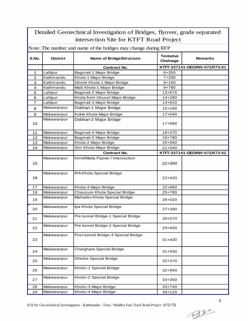
1 Lalitpur Bagmati-1 Major Bridge 6+350
2 Kathmandu Khola-1 Major Bridge 7+290
3 Kathmandu Ghorle Khola-1 Major Bridge 9+160
4 Kathmandu Maiti Khola-1 Major Bridge 9+780
5 Lalitpur Bagmati-2 Major Bridge 13+670
6 Lalitpur Khola from Ghusel Major Bridge 14+280
7 Lalitpur Bagmati-3 Major Bridge 14+610
8 Makawanpur Dobhan-1 Major Bridge 15+290
9 Makawanpur Kokte Khola Major Bridge 17+040
10Makawanpur Dobhan-2 Major Bridge
17+580
11 Makawanpur Bagmati-4 Major Bridge 18+370
12 Makawanpur Bagmati-5 Major Bridge 18+780
13 Makawanpur Khola-2 Major Bridge 20+560
14 Makawanpur Sim Khola Major Bridge 21+040
Contract No.
15
Makawanpur Kimti/Malta Flyover / Intersection
22+000
16
Makawanpur IPA Khola Special Bridge
22+420
17 Makawanpur Khola-3 Major Bridge 22+960
18 Makawanpur Chausure Khola Special Bridge 25+780
19Makawanpur Mahadev Khola Special Bridge
26+020
20Makawanpur Ipa Khola Special Bridge
27+390
21Makawanpur Pre tunnel Bridge-1 Special Bridge
29+070
22Makawanpur Pre tunnel Bridge-2 Special Bridge
29+650
23
Makawanpur Post tunnel Bridge-3 Special Bridge
31+430
24Makawanpur Charghare Special Bridge
31+930
25Makawanpur Dhedre Special Bridge
32+370
26Makawanpur Kholsi-1 Special Bridge
32+940
27Makawanpur Kholsi-2 Special Bridge
33+350
28 Makawanpur Kholsi-3 Major Bridge 33+740
29 Makawanpur Kholsi-4 Major Bridge 34+120
Detailed Geotechnical Investigation of Bridges, flyover, grade separated
intersection Site for KTFT Road Project
Note: The number and name of the bridges may change during RFP
KTFT-337141-GEO/INV-072/073-01
KTFT-337141-GEO/INV-072/073-02

6 EOI for Geo-technical Investigation - Kathmandu - Terai / Madhes Fast Track Road Project (072/73)
Contract No.
30
Makawanpur Kholsi-5 Special Bridge
34+490
31
Makawanpur Jitpur Approach Special Bridge
35+440
32Makawanpur Jitpur River Special Bridge
36+240
33Makawanpur Kholsi (Karan Khola) Special Bridge
36+680
34 Makawanpur Kholsi-6 Major Bridge 37+100
35 Makawanpur Kholsi-7 Major Bridge 38+110
36Makawanpur Bandar Kholsi Special Bridge
38+500
37 Makawanpur Karm Kholsi Major Bridge 39+670
38 Makawanpur Karm Kholsi Major Bridge 39+970
39 Makawanpur Khola-4 Major Bridge 43+020
40 Makawanpur Khola-5 Major Bridge 43+850
41
Makawanpur Budune River Special Bridge
44+510
42 Makawanpur Annapani Khola Major Bridge 45+070
43 Makawanpur Kholsi-8 Major Bridge 46+690
44 Makawanpur Kholsi-9 Major Bridge 47+070
Contract No.
45 Makawanpur Tuni Major Bridge 47+280
46 Makawanpur Kholsi-10 Special Bridge 47+800
47
Makawanpur Budne Flyover / Intersection
48+000
48 Makawanpur Kholsi-11 Major Bridge 49+460
49 Makawanpur Viaduct Major Bridge 50+010
50 Makawanpur Kholsi-12 Major Bridge 50+210
51 Makawanpur Kholsi-13 Major Bridge 50+520
52
Makawanpur Shripur Flyover / Intersection
51+000
53Makawanpur Kholsi-14 Special Bridge
51+200
54 Makawanpur Kholsi-15 Major Bridge 51+820
55
Makawanpur Dung Dung Khola Special Bridge
52+460
56 Makawanpur Kattee Khola Major Bridge 53+280
57 Makawanpur Debre Khola Major Bridge 53+710
58 Makawanpur Khahare Major Bridge 54+240
59 Makawanpur Kholsi-16 Major Bridge 54+470
KTFT-337141-GEO/INV-072/073-03
KTFT-337141-GEO/INV-072/073-04
Detailed Geotechnical Investigation of Bridges, flyover, grade separated
intersection Site for KTFT Road Project
Note: The number and name of the bridges may change during RFP
7 EOI for Geo-technical Investigation - Kathmandu - Terai / Madhes Fast Track Road Project (072/73)
Contract No.
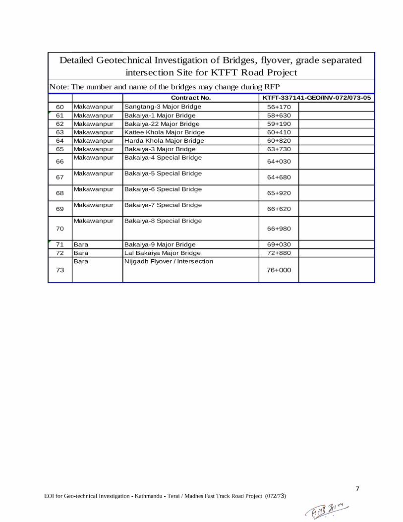
60 Makawanpur Sangtang-3 Major Bridge 56+170
61 Makawanpur Bakaiya-1 Major Bridge 58+630
62 Makawanpur Bakaiya-22 Major Bridge 59+190
63 Makawanpur Kattee Khola Major Bridge 60+410
64 Makawanpur Harda Khola Major Bridge 60+820
65 Makawanpur Bakaiya-3 Major Bridge 63+730
66Makawanpur Bakaiya-4 Special Bridge
64+030
67Makawanpur Bakaiya-5 Special Bridge
64+680
68Makawanpur Bakaiya-6 Special Bridge
65+920
69Makawanpur Bakaiya-7 Special Bridge
66+620
70
Makawanpur Bakaiya-8 Special Bridge
66+980
71 Bara Bakaiya-9 Major Bridge 69+030
72 Bara Lal Bakaiya Major Bridge 72+880
73
Bara Nijgadh Flyover / Intersection
76+000
KTFT-337141-GEO/INV-072/073-05
Detailed Geotechnical Investigation of Bridges, flyover, grade separated
intersection Site for KTFT Road Project
Note: The number and name of the bridges may change during RFP

1
Section 5. Terms of Reference
For Feasibility Study, Detailed Engineering Survey, Soil Investigation and conceptual
(Preliminary) Design of Bridges / Culverts
Name of Bridges, Flyover, Grade Seperated Intersection: Refer attached package list
Name of Road: Refer attached package list
Location: Refer attached package list
1. INTRODUCTION
The Kathmandu – Terai / Madhes Fast Track Road Project, Mid-Baneshwor Kathmandu (hereinafter referred as
"the Project"), intends to utilize services of engineering consulting firms well experienced in the fields of soil
investigation, hydrological studies, bridge engineering, river training works, environment aspects etc. for
providing engineering consulting services for soil investigation and preliminary / conceptual design work of
proposed Bridge(s), Flyovers, Grade separated Intersection and Tunnel.
2. OBJECTIVE
Objective of this job is to investigate sub-surface soil / rock strata as guided by hydrology and prepare report
pertaining to bore log, bearing capacity of strata and preliminary design of Bridge(s), Flyovers, Grade separated
Intersection in order to design a safe, reliable and cost effective bridge, flyover, intersection using the
appropriate technology. The investigation is to be carried out considering the availability of skilled manpower,
equipment, condition of accessibility and other prevailing working conditions.
3. SCOPE OF WORK
The scope of work to be carried out by the consultant shall include but may not be limited to the following:
3.1. Desk study:
A desk study should be carried out, collecting all data, maps and information relevant to bridge design and
reviewing for planning of further field survey and investigation works.
3.2. Feasibility Study :
Feasibility Study shall include the following:
3.2.1. Technical Feasibility study:
It should include reviewing the available data, collecting, reviewing and analysis of field data to be used in the
study and conducting analysis to decide upon the technical feasibility of the bridge site(s). A cost comparison of
different types of bridge shall be made and discussed with the Project before proceeding to bridge site for soil
investigation.
In this study the following points related to the river, its catchment area and all the considered bridge sites should
be studied in detail.
(i) Topography
(ii) Nature and structure of the surface soil
(iii) Nature and structure of local as well as regional geology
(iv) Other information as needed.

2
3.2.2. Topographical Survey
The topographical survey of the area should cover a minimum distance of 500 m upstream, 200 m. downstream
and 200 m from the river banks on either sides of the river at the proposed bridge site. The Topographic map
should show the following:
(i) Contours at 1(one) m. intervals in hilly area and at 0.25 m in plain area.
(ii) Flood lines on either sides of the river in the entire area surveyed.
(iii) Lines with spot levels along which the bed slope of the river is taken
(iv) Both banks of the river
(v) Lines along which cross section of the river is taken
(vi) Govt. and/or public establishments
(vii) Traverse lines, benchmarks reference lines and/or points with respect to which the
present topo map is prepared.
(viii) The angle and direction of skew, if the bridge is proposed to be aligned skew.
(ix) The Names of the nearest identifiable villages/towns etc. in either ends of the bridge.
(x) Other information relevant to design, construction and/or maintenance of the bridge.
(xi) Bridge axis cross section should be taken by level machine and R. L.
computation should be checked with conventional Rise/Fall or Height of
Instrument method.
3.2.3. Hydrological Study
For determination of all design data the consultant shall carry out a detailed hydrometrical survey and
hydrological study of the river and bridge site, which shall include the following:
(i) Catchment area of the river up to bridge site
(ii) Length of the river from origin up to bridge site
(iii) Possibility of change of catchment
(iv) Nature, size and quantities of debris carried by the river
(v) Intensity, duration and distribution of rain in the catchment
(vi) Vegetation, cultivation etc. of the catchment.
(vii) Existence of reservoir's, Lakes etc. in the catchment.
(viii) Existing bridge or other hydraulic structures across the river in the vicinity of the
proposed bridge site with their details as much as possible.
(ix) General slope of the river from the critical point (origin) of the river up to bridge
site and general slope of the catchment in both sides of the river.
(x) Cross sections covering 200m.beyond flood lines of the river at proposed bridge site,
at about 500m. u/s and about 200m d/s. wherein HFL, LWL,LBL, area of the cross
section, wetted perimeter and geological profile with silt factor of each strata (at
proposed bridge site only) shall be indicated. (Horizontal and vertical scale of the
cross section shall be the same)
(xi) Bed slope of the river which must start from 100m. up of the U/S cross section and
end at 100 m. down of the d/s. cross section.
(xii) Maximum discharge calculated by established formulas with different return periods
and the peak discharge observed over a period of 100 years.
(xiii) Velocity and depth of flow at the time of survey.
(xiv) Shifting of the river in the past at proposed bridge site and in its vicinity.

3
(xv) Other information required for river control, design, construction and maintenance of
the bridge.
3.2.4. Site Selection of bridges, flyovers, grade separated intersection and tunnel
Alternative sites shall be studied based on 3.2.1 and the most suitable site for the bridge based on the above
criteria of the site. The selected site should be clearly indicated in the map and all the characteristic features of
the chosen site shall be given, in order to facilitate easy reference while designing the relevant structures.
3.2.5. Seismological Study:
The consultants shall collect and refer to the available data regarding the seismic records of the area. Seismic
Forces: According to the Indian Standard Criteria for Earthquake Resistant Design of Structures, IRC: 6 may be
followed.
3.2.6. Environmental Study
The consultant shall predict damages to the Environment and attempt to mitigate or minimize the damages by
choosing appropriate site, cross-section, type of structures etc. and suggest appropriate measures in the design
for protection of surrounding Environment. The Environmental Protection Act, Environmental Protections Rules
and the DOR environmental policies including Environmental and Social Management Framework (ESMF),
modified by GESU/DOR for bridges should be followed.
3.2.7.
Test pits and auger-holes in the riverbed to a depth as mentioned in the BOQ for determining the mean particle
size of riverbed materials in each layer.
3.2.8. Bore-holes, field tests and laboratory tests
The properties of the underlying soil are determined by field and laboratory tests of the soil samples obtained
from the bore holes drilled to a depth as mentioned in the next section and/or the Bill of Quantities. As far as
possible, the locations of the boreholes shall be under each abutment and piers. Generally the following tests are
conducted for determination of soil properties:
S.N. Type of test Frequency
1 Undisturbed Soil Sampling at least 2 at each borehole
2 Standard Penetration Test as required but the interval not less than 1.5 m
and every change of soil strata
3 Grain size analysis at least 2 at each borehole
4 Hydrometer analysis at least 2 at each borehole
5 Moisture content at least 2 at each borehole
6 Bulk and dry density at least 2 at each borehole
7 Unconfined compression test at least 2 at each borehole
8 Consolidation test at least 2 at each borehole
9 Direct shear test at least 2 at each borehole
If required by the field condition, the Consultant shall conduct other types of tests. Similarly the frequency of the
above tests can be increased if required. The cost of all the field and laboratory tests shall be incorporated in the
cost of soil investigation works. No separate payment shall be made for the tests.
4
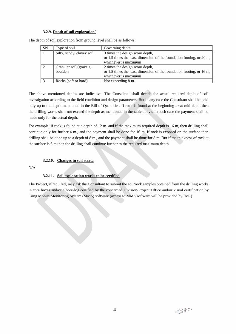
3.2.9. Depth of soil exploration`
The depth of soil exploration from ground level shall be as follows:
SN Type of soil Governing depth
1 Silty, sandy, clayey soil 3 times the design scour depth,
or 1.5 times the least dimension of the foundation footing, or 20 m,
whichever is maximum
2 Granular soil (gravels,
boulders
2 times the design scour depth,
or 1.5 times the least dimension of the foundation footing, or 16 m,
whichever is maximum
3 Rocks (soft or hard) Not exceeding 8 m.
The above mentioned depths are indicative. The Consultant shall decide the actual required depth of soil
investigation according to the field condition and design parameters. But in any case the Consultant shall be paid
only up to the depth mentioned in the Bill of Quantities. If rock is found at the beginning or at mid-depth then
the drilling works shall not exceed the depth as mentioned in the table above. In such case the payment shall be
made only for the actual depth.
For example, if rock is found at a depth of 12 m. and if the maximum required depth is 16 m, then drilling shall
continue only for further 4 m., and the payment shall be done for 16 m. If rock is exposed on the surface then
drilling shall be done up to a depth of 8 m., and the payment shall be done for 8 m. But if the thickness of rock at
the surface is 6 m then the drilling shall continue further to the required maximum depth.
3.2.10. Changes in soil strata
N/A
3.2.11. Soil exploration works to be certified
The Project, if required, may ask the Consultant to submit the soil/rock samples obtained from the drilling works
in core boxes and/or a bore-log certified by the concerned Division/Project Office and/or visual certification by
using Mobile Monitoring System (MMS) software (access to MMS software will be provided by DoR).
5
3.2.12. Other information
Availability of construction materials like, sand gravel boulders, timber, etc. with their engineering properties,
quantities and lead up to the bridge site, quarry site of materials with their available quantities should be
shown on a sketch plan with reference to Bridge site.
3.3. Analysis of Data, Conclusion and Recommendation of Design Parameters.
Based upon the above mentioned studies and investigations the consultants shall make the best use of their
technical know-how and professional skill to arrive at and recommend the most cost effective design parameters.
The consultant shall discuss in detail at least three different options and shall recommend the most appropriate
option.
3.4. Miscellaneous
If not covered by aforesaid, the Consultants shall perform other studies, explorations, tests surveys, calculations,
etc. required to produce full and complete set of working drawings.
If it is decided to use any Standard Design, the Payments shall be adjusted according to the Conditions of
Contract and/or as mentioned in the BOQ.
3.5. The checklist
The detailed requirements of the design report are given in the checklist at the end of this TOR. Before
submitting the report the consultants should verify whether it complies with the checklist.
4. SUBMISSION OF REPORTS AND PRESENTATION OF THE WORKS
In accordance with DOR's standard and procedures the consultant shall submit his reports as under:
4.1. Inception Report
This report shall contain bridge location with alternatives, cross-section of bridge axis of each alternatives
showing hydrological and geological elements, bank conditions, general geology, general hydrology, location
plan, social acceptability, tentative bridge type with length, span arrangement etc. This shall contain Index map
as well as location map of the bridge with respect to main road network. Inception report shall be submitted to
the Project in one copy and shall be presented in MOPIT, Singhdurbar.
4.2. Field Report & Preliminary Design Report
This report will contain bridge site plan showing alignment of bridge foundations and locations of bore
holes, logs with description of samples taken at every change of strata. Preliminary field report shall be
submitted to the Project in two copies and should be discussed with the Project / MOPIT.
This report shall contain the preliminary design concepts and short descriptions relating to the proposed structure
and its major components, e.g. superstructure, pier, foundations river training/ bank protection structures,
approach road etc. It shall include location of proposed foundations and arrangement of the bridge components
along with comparison between the possible alternative types. (Please also see Clause 3.7, Use of
Standard Designs). This report shall be submitted in three copies and the content shall be discussed with the
Project / MOPIT before proceeding to the detailed design of the bridge. The Project / MOPIT may also ask
6
to present the Preliminary Design Report to the Project / DOR / MOPIT audience. The cost of such
presentation shall be borne by the Consultants.
4.3. Draft Report
This report shall in all respect be complete, containing all the required components of the design and be
presented in clear and easy to refer formats as per the general design guidance attached. The complete set of the
report shall consist of:
(i) Volume I – Main Report
(ii) Volume II – Drawings
(iii) Appendices
Please refer to the checklist provided with this TOR for number of copies and detailed requirements of the
reports. The Report shall also include the drawings,
Presentation of the Draft Report
The Consultants shall present the design report in specified format and defend it to the Project / DOR / MOPIT
audience prior to the submission of the final report. They shall review the issues raised during the presentation
while finalizing the report and make necessary amendments/corrections if needed. The date and venue of the
presentation shall be determined by mutual agreement between the Bridge Branch and the consultants. The cost
of such presentation shall be borne by the consultants.
4.4. Final Report
Apart from the presentation, the Project / MOPIT will verify the content of the report against the Terms of
Reference and the checklist. The Project may also discuss upon the technical content of the report and may
suggest some changes if thought necessary. While preparing the Final Report the consultants shall consider the
comments/suggestions and make corrections or amendments if required. It does not, however, relieve the
consultants of their responsibility over the technical content of the design. The final report shall be submitted in
stipulated number of copies as indicated in the checklist.
4.5. Soft copy (electronic copy) of the design report
Apart from the bound report the consultants shall submit soft copies (electronic copies) of the final report in
suitable tool as specified in the checklist.
5. TIME SCHEDULE
If not indicated otherwise in the contract documents the consultant shall complete the assigned works as per the
following schedule:
(i) Inception Report within 3 (Three) weeks started from the date of signing of the Agreement.
(ii) Field Report & Preliminary Design Report within 10 (Ten) weeks started from the date of signing
of the Agreement.
(ii) Draft Report within 12 (Twelve) weeks started from the date of signing of the Agreement.
(iii) Final Report within 2 (Two) weeks after receiving the Project / MOPIT comments and
suggestions on the draft report.
7
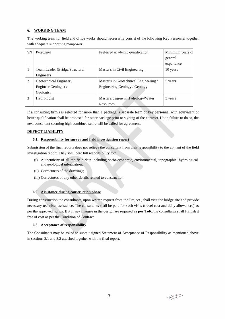
6. WORKING TEAM
The working team for field and office works should necessarily consist of the following Key Personnel together
with adequate supporting manpower.
SN Personnel Preferred academic qualification Minimum years of
general
experience
1 Team Leader (Bridge/Structural
Engineer)
Master's in Civil Engineering 10 years
2 Geotechnical Engineer /
Engineer Geologist /
Geologist
Master's in Geotechnical Engineering /
Engineering Geology / Geology
5 years
3 Hydrologist Master's degree in Hydrology/Water
Resources
5 years
If a consulting firm/s is selected for more than 1 package, a separate team of key personnel with equivalent or
better qualification shall be proposed for other package prior to signing of the contract. Upon failure to do so, the
next consultant securing high combined score will be called for agreement.
DEFECT LIABILITY
6.1. Responsibility for survey and field investigation report
Submission of the final reports does not relieve the consultant from their responsibility to the content of the field
investigation report. They shall bear full responsibility for:
(i) Authenticity of all the field data including socio-economic, environmental, topographic, hydrological
and geological information;
(ii) Correctness of the drawings;
(iii) Correctness of any other details related to construction
6.2. Assistance during construction phase
During construction the consultants, upon written request from the Project , shall visit the bridge site and provide
necessary technical assistance. The consultants shall be paid for such visits (travel cost and daily allowances) as
per the approved norms. But if any changes in the design are required as per ToR, the consultants shall furnish it
free of cost as per the Condition of Contract.
6.3. Acceptance of responsibility
The Consultants may be asked to submit signed Statement of Acceptance of Responsibility as mentioned above
in sections 8.1 and 8.2 attached together with the final report.

8
Checklist for Detailed survey and design of bridges
This paper serves as a guideline for checking the detailed engineering survey and design of bridges,
received from the consultants.
General procedure for checking the design report:
Checklist for content of the package:
Particulars Required information / number / range / value(s)
Volume I - Main report Draft – 2 copies; Final – 3 copies
Volume II – Drawings with calculation Draft – 2 copies; Final – 3 copies
Soft (electronic) copies of the report 2 copies in CD-ROM with hard plastic case
1. Content of Main Report (Volume I)
1.1 Statement of acceptance of responsibility
A signed acceptance of responsibility to the authenticity of field data and correctness of design shall
be attached to each copy of the main report.
1.2 Salient features:
Particulars Required information / number / range / value(s)
Name of the Project : Job description as mentioned in the work-order
Location :
Development Region Central
Zone Bagamati / Narayani
District Kathmandu / Lalitpur / Makawanpur / Bara
Village/town Name of the surrounding VDC/town/municipality or any pertinent
landmark in the vicinity of the bridge.
Name of the Road : Popular / formal name of the road (e.g. East – West Highway) and road
reference number from the SRN data (if applicable)
Origin and Destination of
the Road
Kathmandu – Nijgadh
Chainage of the Bridge Site chainage from the origin of the road
Geographical Location :
Easting East coordinate
Northing North coordinate
Classification of the Road Asian Highway Primary Class Standard – Acess Controlled Exressway
Type of the road surface BT / Concrete
Terrain / Geology General terrain (Hill, mountain or plain) and general geology
Information on structure:
Total length of the bridge Total length between edges of the end decks
Span arrangement Number x effective lengths of spans
Total width of the bridge: Total width between edges of the deck i.e, the Formation Width = 23.5m
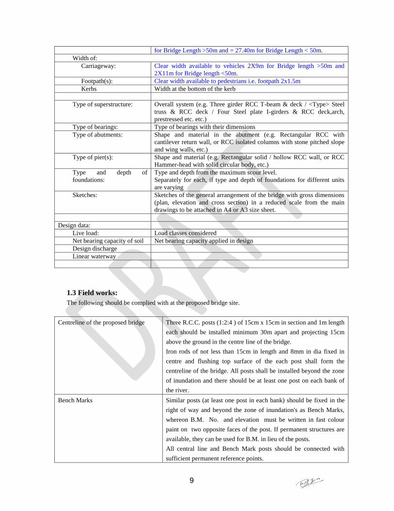
9
for Bridge Length >50m and = 27.40m for Bridge Length < 50m.
Width of:
Carriageway: Clear width available to vehicles 2X9m for Bridge length >50m and
2X11m for Bridge length <50m.
Footpath(s): Clear width available to pedestrians i.e. footpath 2x1.5m
Kerbs Width at the bottom of the kerb
Type of superstructure: Overall system (e.g. Three girder RCC T-beam & deck / <Type> Steel
truss & RCC deck / Four Steel plate I-girders & RCC deck,arch,
prestressed etc. etc.)
Type of bearings: Type of bearings with their dimensions
Type of abutments: Shape and material in the abutment (e.g. Rectangular RCC with
cantilever return wall, or RCC isolated columns with stone pitched slope
and wing walls, etc.)
Type of pier(s): Shape and material (e.g. Rectangular solid / hollow RCC wall, or RCC
Hammer-head with solid circular body, etc.)
Type and depth of
foundations:
Type and depth from the maximum scour level.
Separately for each, if type and depth of foundations for different units
are varying
Sketches: Sketches of the general arrangement of the bridge with gross dimensions
(plan, elevation and cross section) in a reduced scale from the main
drawings to be attached in A4 or A3 size sheet.
Design data:
Live load: Load classes considered
Net bearing capacity of soil Net bearing capacity applied in design
Design discharge
Linear waterway
1.3 Field works:
The following should be complied with at the proposed bridge site.
Centreline of the proposed bridge Three R.C.C. posts (1:2:4 ) of 15cm x 15cm in section and 1m length
each should be installed minimum 30m apart and projecting 15cm
above the ground in the centre line of the bridge.
Iron rods of not less than 15cm in length and 8mm in dia fixed in
centre and flushing top surface of the each post shall form the
centreline of the bridge. All posts shall be installed beyond the zone
of inundation and there should be at least one post on each bank of
the river.
Bench Marks Similar posts (at least one post in each bank) should be fixed in the
right of way and beyond the zone of inundation's as Bench Marks,
whereon B.M. No. and elevation must be written in fast colour
paint on two opposite faces of the post. If permanent structures are
available, they can be used for B.M. in lieu of the posts.
All central line and Bench Mark posts should be connected with
sufficient permanent reference points.
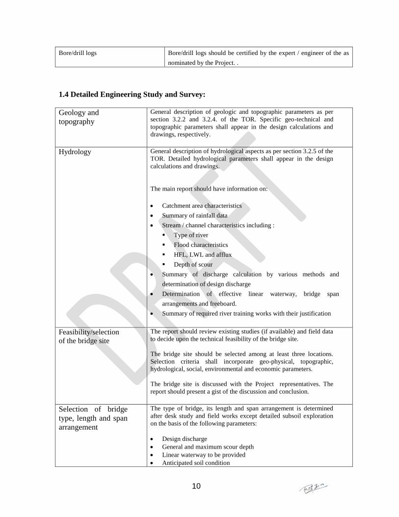
10
Bore/drill logs Bore/drill logs should be certified by the expert / engineer of the as
nominated by the Project. .
1.4 Detailed Engineering Study and Survey:
Geology and
topography
General description of geologic and topographic parameters as per
section 3.2.2 and 3.2.4. of the TOR. Specific geo-technical and
topographic parameters shall appear in the design calculations and
drawings, respectively.
Hydrology General description of hydrological aspects as per section 3.2.5 of the
TOR. Detailed hydrological parameters shall appear in the design
calculations and drawings.
The main report should have information on:
Catchment area characteristics
Summary of rainfall data
Stream / channel characteristics including :
Type of river
Flood characteristics
HFL, LWL and afflux
Depth of scour
Summary of discharge calculation by various methods and
determination of design discharge
Determination of effective linear waterway, bridge span
arrangements and freeboard.
Summary of required river training works with their justification
Feasibility/selection
of the bridge site
The report should review existing studies (if available) and field data
to decide upon the technical feasibility of the bridge site.
The bridge site should be selected among at least three locations.
Selection criteria shall incorporate geo-physical, topographic,
hydrological, social, environmental and economic parameters.
The bridge site is discussed with the Project representatives. The
report should present a gist of the discussion and conclusion.
Selection of bridge
type, length and span
arrangement
The type of bridge, its length and span arrangement is determined
after desk study and field works except detailed subsoil exploration
on the basis of the following parameters:
Design discharge
General and maximum scour depth
Linear waterway to be provided
Anticipated soil condition

11
Selected bridge site
River training and approach road
Construction/maintenance cost
Availability of material and labour
The report should present a comparative evaluation of different types
of bridges on the basis of the above parameters. The type of bridge is
discussed with the Project before proceeding to soil investigation.
design pertaining to the selection of the type of structures (bridges,
flyovers, grade separated intersections). The report should include the
gist of discussion and conclusion.
Environmental study The report should review the project as per the Environmental Protection Act,
Environment Protection Rules and DOR environmental policies including
Environmental and Social Management Framework (ESMF), modified by
GESU/DOR for bridges .
Seismological study The report should review the information and past seismic records of
the project area as per section 3.2.6 of the TOR.
Sub-surface
exploration
The subsurface exploration shall proceed after final selection of the
bridge type and axis conforming to the requirement as per section 3.3
of the TOR. The main report should include the following:
General description of the subsoil strata
Bore logs
Sectional elevation of the subsoil strata showing locations of
bore-holes and proposed foundations
Net bearing capacity, selection of foundation and its depth on the
basis of the above parameters.
Detailed analysis of subsoil strata and test results shall appear in
Design Calculations and Appendix-1
1.5 Detailed analysis and design calculation of following elements should be provided.
The design calculations should mention the governing design code or guideline
wherever they are applied.
Hydrology
Hydrological data Catchment area characteristics:
- The catchment area size, shape (classified as fan, pear, long or
narrow), slopes (Longitudinal and Cross-sectional).
- Surface characteristics (whether sandy, clayey etc. including
percolation and interception characteristics.
- Whether land is under forestation, deforestation or is dotted with
urban areas, cultivated areas or storage areas, e.g. lakes, swamps,
tanks, reservoirs etc. shall be determined.
Rainfall Data:
12
- Maximum in 24 hours.
- Maximum in any one hours.
- Rainfall distribution in the catchment area.
- Duration and frequency of the rain.
- Raingauge data of the storms along with the corresponding stream
gauss data (data for unit hydrograph).
- Average annual rainfall characteristics (from relevant
meteorological records).
- Probability plotting (a graph plotted between the flood magnitude
against its return period).
Stream / channel characteristics
1. Type of river
- Seasonal or Perennial.
- Meandering or Straight.
- Other classification, e.g. boulderly, flashy, well defined, tidy etc.
- Length, slope, cross-sections of the river.
2. Water Level
- Highest flood in living memory and other major floods before
start of investigation.
- Highest flood level and year of its occurrence, showing the areas
flooded.
- Records of flood gauging stations.
- Lowest Water Level (LWL).
- Afflux, if observed.
- Observed maximum depth of scour and scour level, indicating
what obstruction if any, and other special causes, which can be
responsible for the scour at site.
- Sediment Data, indicating bed material particle size, aggradations
(degradation of bed, bank erosion (reference to flood stage) etc.
- Erodibility of riverbanks and river bed.
- Scour Data (as observed, particularly downstream of any
obstructions to the flood flow).
Analysis of
hydrological data
and determination
of associated
elements
Discharge calculation by various methods including WECS method,
comparison of discharges, determination of design discharge expected to
pass under the bridge and justification for adapting the design discharge,
natural stream velocity and flood velocity.
Maximum mean or maximum velocity of flood flow.
Effective linear waterway required under the bridge (after allowing for
average thickness of each pier and its foundation, between High Flood
Level and Normal Scour Level, ignoring the earth fills in front of the

13
abutment).
High Flood Level, Afflux and Water Level.
Freeboard required between the affluxed High Flood Level and soffit of
deck from the considerations of unobstructed flow of floating debris with
the flood discharge.
Normal and Design (maximum) scour levels at piers and abutments
(Consider higher watermarks in the area and at and near the site).
Minimum founding levels at piers and abutments from consideration of
maximum scour etc.
Sub-soil
investigation.
Investigation data Bore-log of each bore-hole showing: Depth gauge, soil description of
encountered layers with depth marks, sample collection points, depth and
types of tests performed, Ground water table, number of blows for
SPT/CPT, N-values
Certificate of sub-soil investigation from respective Division / project
office indicating depth of each bore-hole and confirming that soil-
samples of each strata in each borehole are deposited in core boxes for
the record.
Laboratory test result of the samples as specified in section 3.3 of the
TOR.
Analysis of sub-
soil data
Determination of bearing capacity and other parameters at different depths
required for different types of foundations, determination of design bearing
capacity.
Comparison and determination of type(s) of foundation for abutments and
piers.
Summary of subsoil characteristics and types of foundations.
Preliminary
Design of bridge
elements
On the basis of the topographic survey, hydrological, sub-soil and
seismological analysis the report should present preliminary design of the
following parts of the bridge:
Design of superstructure and its parts: deck, main and cross girders,
bearings, railing posts, bracings, stiffeners, joints etc. as applicable.
Design of substructure: pier/abutment cap, substructure body
Design of foundation and its part: foundation base, well/pile cap, well
steining, pile grouping, individual pile body, pile head, cutting edge,
top/bottom plug as applicable.
Design of river training works
Design of approach roads
14
5. Soft (electronic) copies of the part of the report
Two copies of the report in electronic files should be submitted in suitable tool, which
shall include the following:
Text of main report (in MS Word format)
Rate analysis and cost estimates (in MS Excel format)
All the drawings in format compatible to AutoCAD.
6. Appendices
The following should be submitted as appendices to the main report:
1. Laboratory test results of subsoil strata as specified in section 3.3 of the TOR
2. Detailed rate analysis
3. Certified district rates