Embed Size (px)
Citation preview
electronics
Article
Microwave Staring Correlated Imaging Based onTime-Division Observation and DigitalWaveform Synthesis
Jianlin Zhang , Bo Yuan , Zheng Jiang, Yuanyue Guo and Dongjin Wang *
Key Laboratory of Electromagnetic Space Information, Chinese Academy of Sciences,University of Science and Technology of China, Hefei 230026, China; [email protected] (J.Z.);[email protected] (B.Y.); [email protected] (Z.J.); [email protected] (Y.G.)* Correspondence: [email protected]
Received: 16 July 2020; Accepted: 22 September 2020; Published: 2 October 2020�����������������
Abstract: As a newly proposed high resolution computational imaging technique, Microwave StaringCorrelated Imaging (MSCI) requires elaborate design of the temporal-spatial stochastic radiation fields(TSSRF). Conventional implementation of MSCI radiation source consists of multiple transmittersconfiguration and simultaneous emitting scheme, which remains underutilization of the availabledesign resources. In this paper, a time-division MSCI (TD-MSCI) method is proposed to virtuallygenerate the TSSRF and make further use of the available design resources. Different from conventionsimultaneously transmitting based MSCI, the detection scheme in TD-MSCI is achieved by alternatelytransmitting of each transmitter, rather than simultaneous transmission of multiple transmitters.Echo enhancement is conducted to improve the SNR level of the echo waveform and to resolvethe power coastdown caused by single transmitting scheme. Unused combinations of existingresources are digitally synthesized in computer rather than taking extra observations in actualphysical environment. After the processing of time division observation, echo enhancement anddigital waveform synthesis, extending TSSRF with better stochastic characteristics are generated,and improved imaging performance is obtained. Numerical imaging experiments and preliminaryreal-world imaging experiment verify the effectiveness of the proposed TD-MSCI, demonstratingthat the proposed method increases the flexibility in radiation source design and decreases thedetection costs.
Keywords: microwave staring correlated imaging; time division observation; echo enhancement;digital waveform synthesis
1. Introduction
Inspired by optical Ghost Imaging (GI) [1,2], Microwave Staring Correlated Imaging (MSCI) isa newly proposed high resolution microwave computational imaging technique, where the radarsystem is usually carried on a stationary or quasi-stationary platform [3,4]. The essential principle ofMSCI is to construct the temporal-spatial stochastic radiation fields (TSSRF), which possess stochasticcharacteristics both in spatial distribution and time domain. By the correlation process betweenscattering echo and the pre-designed radiation fields, targets within antenna beam can be reconstructedwith higher resolution than the Real Aperture Radar (RAR). Previous research has indicated that,MSCI achieves superior imaging performance in staring observation applications and thus has attractedincreasing attention in many aspects [5–8].
The imaging resolution of MSCI is mainly determined by the stochastic characteristics of TSSRF,or the property of the imaging matrix. By illuminating the imaging region with temporal-spatial
Electronics 2020, 9, 1627; doi:10.3390/electronics9101627 www.mdpi.com/journal/electronics

Electronics 2020, 9, 1627 2 of 16
stochastic radiation fields, neighboring scattering centers within the beam are marked by the diverseradiation field. Scattering echoes from targets at different positions in the imaging region possessdiverse temporal characteristics, providing the possibility of targets decoupling. To implementthe pre-designed TSSRF in the region of interest, a multi-transmitters architecture where multipletransmitters simultaneously emit randomly modulated waveforms is commonly adopted in MSCI,which requires elaborate designs of the Random Radiation Source (RRS). The literature demonstratedprogress on the following two main aspects in RRS design—the stochastic multi-channel waveformdesign and the transmitting array design.
In waveform design, considering practical engineering limitations in actual radar systems suchas bandwidth limitation and maximum output power limitation, randomly modulated waveforms,rather than ideal white noise signals, are adopted in MSCI, such as random amplitude modulatedsignals, random phase modulated signals, random frequency hopping signals, and so forth [9–12].Among the above mentioned randomly modulated waveforms, random Frequency Hopping (FH)signal is most commonly employed because of its constant-envelope feature and frequency agility,which makes FH signal practical and manageable in MSCI systems. An optimization algorithm wasadopted to acquire a well-behaved frequency code design of the FH signals based on minimizingthe condition number of the imaging matrix [13]. In addition to waveform design, optimizing thedesign of the transmitting array also contributes to improving stochastic characteristic of TSSRF.Temporal–Spatial Distribution Entropy (TSDE) was proposed in Reference [14] as the optimizationtarget of the array configuration design. A novel bi-static MSCI architecture was presented inReference [15] to observe the targets from larger aspect angles and to form TSSRF with better stochasticfeatures. Owing to the abundant designs of MSCI radiation source, well behaved TSSRF are generatedin the imaging region and targets are reconstructed with high resolution.
However, though opitimization methods on stochastic waveform design and transmitting arraydesign can be used to improve the property of the TSSRF and the imaging matrix, some defects are alsointroduced into MSCI by the simultaneous emitting scheme at the same time. The TSSRF are physicallygenerated in the imaging region based on simultaneous transmitting of multiple transmitters, and shouldbe accurately estimated and computed in the correlated processing according to pre-designed parametersof the system. On one hand, simultaneous transmitting scheme requires high time precision during theobservation procedure in MSCI, especially the multichannel synchronization. The diverse parametersapplied to different transmitters represent individual control of each transmitter, which strikinglyincreases the system cost and system complexity. On the other hand, once the design of radiationsource is optimized, for example, the array configurations and waveform parameters such as hoppingfrequency sequences in random FH based MSCI are optimized, the TSSRF are hence determined.The physically superposed radiation fields cannot be directly split into individual electromagneticfields radiated from each single transmitter. Thus the property of the imaging matrix and the imagingperformance is pre-determined by the pre-designed radiation sources, and new patterns of TSSRFrequire extra observation cost, even when rearranging the utilized design parameters. Thus the fixedsource design leaves out quite a number of unutilized resources, representing that the available designresources are underutilized.
In this paper, we propose a Time-Division MSCI (TD-MSCI) method to “virtually”, rather thanphysically generate the TSSRF, and make further use of the available resources in radiation source design.Different from conventional MSCI where all transmitters simultaneously radiate electromagneticwaves, the proposed TD-MSCI utilizes an alternate time-division observation scheme of each singletransmitter to detect the imaging targets. Considering that the time division scheme of alternatesingle transmission obviously leads to power coastdown compared with simultaneous emittingscheme of multiple transmitters, which worsens the Signal to Noise Ratio (SNR) and shortens theradar detecting range, echo enhancement is proposed to improve the SNR of the scattering echo andapproximately approach the actual SNR levels in multiple transmitters based MSCI. After flexiblyrearranging and recombining the radiation fields, the feasible TSSRF are virtually generated and
Electronics 2020, 9, 1627 3 of 16
extended. The scattering echoes should also be reorganized according to the extending strategy of theTSSRF. The rearrangement of radiation fields and the corresponding echoes form the digital waveformsynthesis procedure. Finally, correlated processing of the extending TSSRF with corresponding echoesis conducted to obtain well-behaved imaging performance with simplified system architecture.
The rest of the paper is organized as follows. The formulation of MSCI is demonstrated inSection 2, and the imaging performance based on matrix perturbation theory is illustrated as well.In Section 3, the procedures of TD-MSCI are proposed. In Section 4, numerical imaging experiments arewith random FH waveforms, and microwave anechoic chamber imaging experiment are conducted toverify the effectiveness of the proposed TD-MSCI method. Finally, the paper is concluded in Section 5.
2. Formulation and Imaging Performance of MSCI
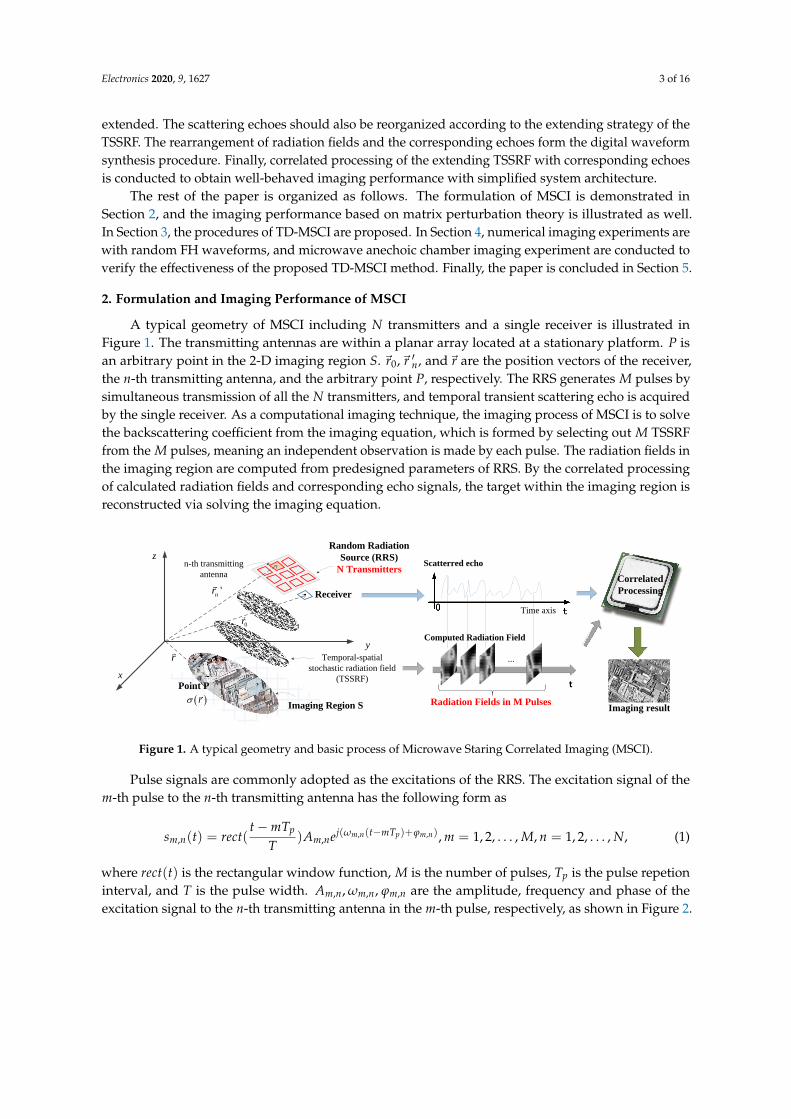
A typical geometry of MSCI including N transmitters and a single receiver is illustrated inFigure 1. The transmitting antennas are within a planar array located at a stationary platform. P isan arbitrary point in the 2-D imaging region S. ~r0,~r ′n, and~r are the position vectors of the receiver,the n-th transmitting antenna, and the arbitrary point P, respectively. The RRS generates M pulses bysimultaneous transmission of all the N transmitters, and temporal transient scattering echo is acquiredby the single receiver. As a computational imaging technique, the imaging process of MSCI is to solvethe backscattering coefficient from the imaging equation, which is formed by selecting out M TSSRFfrom the M pulses, meaning an independent observation is made by each pulse. The radiation fields inthe imaging region are computed from predesigned parameters of RRS. By the correlated processingof calculated radiation fields and corresponding echo signals, the target within the imaging region isreconstructed via solving the imaging equation.
Point P
r
0r
'nr
n-th transmitting
antenna
Receiver
Imaging Region S r
y
z
x
Random Radiation
Source (RRS)
N Transmitters
Temporal-spatial
stochastic radiation field
(TSSRF)
...
Computed Radiation Field
Scatterred echo
Time axis
Imaging result
Correlated
Processing
t
Radiation Fields in M Pulses
Figure 1. A typical geometry and basic process of Microwave Staring Correlated Imaging (MSCI).
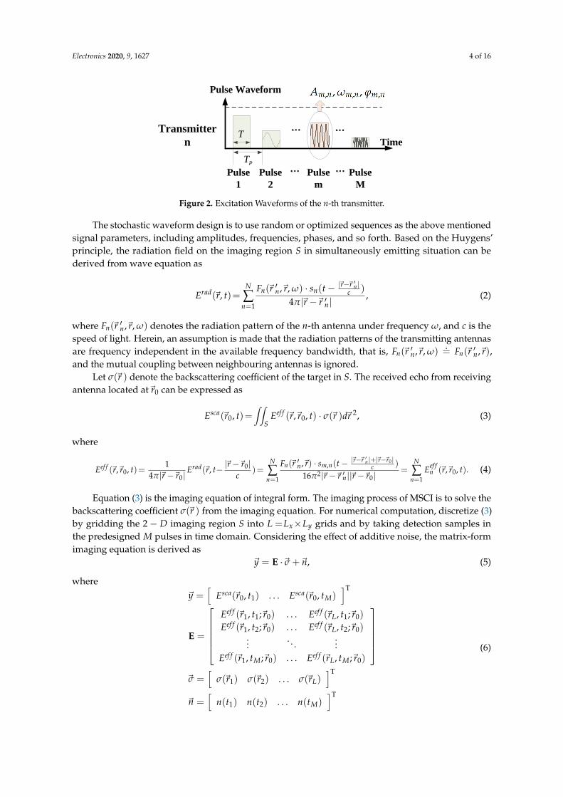
Pulse signals are commonly adopted as the excitations of the RRS. The excitation signal of them-th pulse to the n-th transmitting antenna has the following form as
sm,n(t) = rect(t−mTp
T)Am,nej(ωm,n(t−mTp)+ϕm,n), m = 1, 2, . . . , M, n = 1, 2, . . . , N, (1)
where rect(t) is the rectangular window function, M is the number of pulses, Tp is the pulse repetioninterval, and T is the pulse width. Am,n, ωm,n, ϕm,n are the amplitude, frequency and phase of theexcitation signal to the n-th transmitting antenna in the m-th pulse, respectively, as shown in Figure 2.
Electronics 2020, 9, 1627 4 of 16
Time
Pulse Waveform
…
PT
T
Pulse
1
Pulse
2
Pulse
M
…Pulse
m
…
…
Transmitter
n
Figure 2. Excitation Waveforms of the n-th transmitter.
The stochastic waveform design is to use random or optimized sequences as the above mentionedsignal parameters, including amplitudes, frequencies, phases, and so forth. Based on the Huygens’principle, the radiation field on the imaging region S in simultaneously emitting situation can bederived from wave equation as
Erad(~r, t)=N
∑n=1
Fn(~r ′n,~r, ω) · sn(t− |~r−~r′n |
c )
4π|~r−~r ′n|, (2)
where Fn(~r ′n,~r, ω) denotes the radiation pattern of the n-th antenna under frequency ω, and c is thespeed of light. Herein, an assumption is made that the radiation patterns of the transmitting antennasare frequency independent in the available frequency bandwidth, that is, Fn(~r ′n,~r, ω)
.= Fn(~r ′n,~r),
and the mutual coupling between neighbouring antennas is ignored.Let σ(~r ) denote the backscattering coefficient of the target in S. The received echo from receiving
antenna located at~r0 can be expressed as
Esca(~r0, t)=∫∫
SEef f (~r,~r0, t) · σ(~r )d~r 2, (3)
where
Eef f (~r,~r0, t)=1
4π|~r−~r0|Erad(~r, t− |~r−~r0|
c)=
N
∑n=1
Fn(~r ′n,~r) · sm,n(t− |~r−~r′n |+|~r−~r0|
c )
16π2|~r−~r ′n||~r−~r0|=
N
∑n=1
Eef fn (~r,~r0, t). (4)
Equation (3) is the imaging equation of integral form. The imaging process of MSCI is to solve thebackscattering coefficient σ(~r ) from the imaging equation. For numerical computation, discretize (3)by gridding the 2− D imaging region S into L =Lx×Ly grids and by taking detection samples inthe predesigned M pulses in time domain. Considering the effect of additive noise, the matrix-formimaging equation is derived as
~y = E ·~σ +~n, (5)
where~y =
[Esca(~r0, t1) . . . Esca(~r0, tM)
]T
E =
Eef f (~r1, t1;~r0) . . . Eef f (~rL, t1;~r0)
Eef f (~r1, t2;~r0) . . . Eef f (~rL, t2;~r0)...
. . ....
Eef f (~r1, tM;~r0) . . . Eef f (~rL, tM;~r0)
~σ =
[σ(~r1) σ(~r2) . . . σ(~rL)
]T
~n =[
n(t1) n(t2) . . . n(tM)]T
(6)
Electronics 2020, 9, 1627 5 of 16
The M×L matrix E is called the imaging matrix or sensing matrix. Based on the objectiveof minimizing imaging error, the scattering coefficient ~σ can be reconstructed by solving inverseproblem (5) with Least Square (LS) method, described as
~σ = arg min~σ
{‖~y− E ·~σ‖2
2
}. (7)
In noise free situation, a full-column rank imaging matrix E contributes to accurate reconstructionof~σ, that is, rank(E)=L, which requires M≥L potentially. The square matrix EHE is thus invertibleand the target can be accurately reconstructed under noise free condition. The accurate reconstructionof the imaging target means the resolution of MSCI achieves the grid size in the imaging region S.
Then under noise condition, the imaging performance, measured by relative imaging error (RIE),satisfies the following inequality according to norm compatibility as
RIE =‖∆~σ‖‖~σ‖ =
∥∥∥~σ−~σ∥∥∥‖~σ‖ ≤
cond(EHE) · ‖~n‖‖~y−~n‖ , M>L
cond(E) · ‖~n‖‖~y−~n‖ , M=L,(8)
where cond(E) is the condition number of E, ‖~σ‖ is l2-norm of vector ~σ, and ‖~y−~n‖2/‖~n‖2
approximately equals to SNR.
3. Time-Division Scheme of MSCI
In conventional multi-transmitters based MSCI where simultaneously emitted randomlymodulated waveforms are adopted, parameters of radiation source refer to the amplitudes, frequencies,phases and antenna locations involved in the imaging matrix E. After optimization designs of the aboveparameters, a family of pre-designed stochastic radiation fields is thus determined and generated.The actual radiation field in the imaging region is the linear superposition of individual radiationfields from each single transmitting antenna according to electromagnetic field theory.
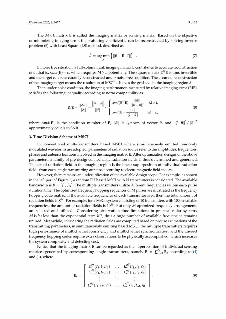
However, there remains an underutilization of the available design scope. For example, as shownin the left part of Figure 3, a random FH based MSCI with N transmitters is considered. The availablebandwidth is B = [ fL, fH ]. The multiple transmitters utilize different frequencies within each pulseduration time. The optimized frequency hopping sequences of M pulses are illustrated as the frequencyhopping code matrix. If the available frequencies of each transmitter is K, then the total amount ofradiation fields is KN . For example, for a MSCI system consisting of 10 transmitters with 1000 availablefrequencies, the amount of radiation fields is 1030. But only M optimized frequency arrangementsare selected and utilized. Considering observation time limitations in practical radar systems,M is far less than the exponential term KN , thus a huge number of available frequencies remainsunused. Meanwhile, considering the radiation fields are computed based on precise estimations of thetransmitting parameters, in simultaneously emitting based MSCI, the multiple transmitters requireshigh performance of multichannel consistency and multichannel synchronization, and the unusedfrequency hopping codes require extra observations to be physically accomplished, which increasesthe system complexity and detecting cost.
Notice that the imaging matrix E can be regarded as the superposition of individual sensingmatrices generated by corresponding single transmitters, namely E = ∑N
n=1 En according to (4)and (6), where
En =
Eef f
n (~r1, t1;~r0) . . . Eef fn (~rL, t1;~r0)
Eef fn (~r1, t2;~r0) . . . Eef f
n (~rL, t2;~r0)...
. . ....
Eef fn (~r1, tM;~r0) . . . Eef f
n (~rL, tM;~r0)
. (9)
Electronics 2020, 9, 1627 6 of 16
Time
f
Lf
HfTransmitter
N……
PT
T
Pulse
1
Pulse
2
Pulse
M
Time
Frequency f
Lf
HfTransmitter
1……
TimeLf
HfTransmitter
2……
…………
……
Conventional MSCI
Pulse
3
1,1f
1,2f
1,Nf2,Nf
2,2f
2,1f,1Mf
,2Mf
,M Nf
…
…
…
… … … …
Frequency Hopping Code Matrix
M Combinations
Time
Frequency f
Lf
Hf
……
TimeLf
Hf
……
TimeLf
Hf
……
1,1f
1,2f
1,Nf
…
…
…
… … … … …
New Frequency Hopping Code Matrix under TD Observation
KN Combinations when K1=K2=…=KN=K
Time Division MSCI
K1 Pulses K2 Pulses KN Pulses
… ………
2,1f
2,Nf
2,2f
2,1f …
…
…
,1Mf
,2Mf
,M Nf
Same FH Codes ,2Mf
,M Nf
Rearranged
FH Codes
f f
f
Time Time
Time
…… …… …… …………
…… ……
K1 Echoes K2 Echoes KN Echoes
Original Echo Original Echo
Synthesized Echo
M Echoes
M Echoes Echo
(M+1) ……
……
……
Digital
Waveform
Synthesis
Of
Echo Signals
Figure 3. Comparison of random frequency hopping MSCI and time division MSCI.
According to matrix theory, the rank of the imaging matrix E satisfies
rank(E)= rank(N
∑n=1
En)≤ rank(
E1
E2...
EN
) ∆= rank(E), (10)
where E denotes partitioned matrix consisting of E1, E2 , . . . , EN .Therefore, when the imaging matrix E is full column rank, namely rank(E) = L ≤ M, the division
and recombination of the imaging matrix forms a new full column rank matrix E, which satisfiesrank(E) = L. The physical meaning of the partitioned matrix E is that the targets are illuminated byindividual single transmitters alternately with the same design parameters in simultaneously emitting
Electronics 2020, 9, 1627 7 of 16
scheme, which can be regarded as a time-division observation, as demonstrated in the right partof Figure 3. The full rank property of the modified imaging matrix E means that the time-divisionobservation maintains the same resolution as simultaneously emitting MSCI.
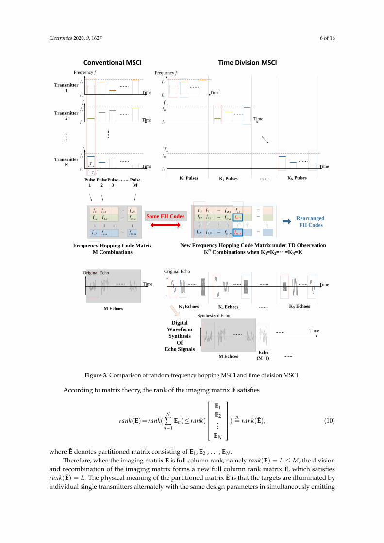
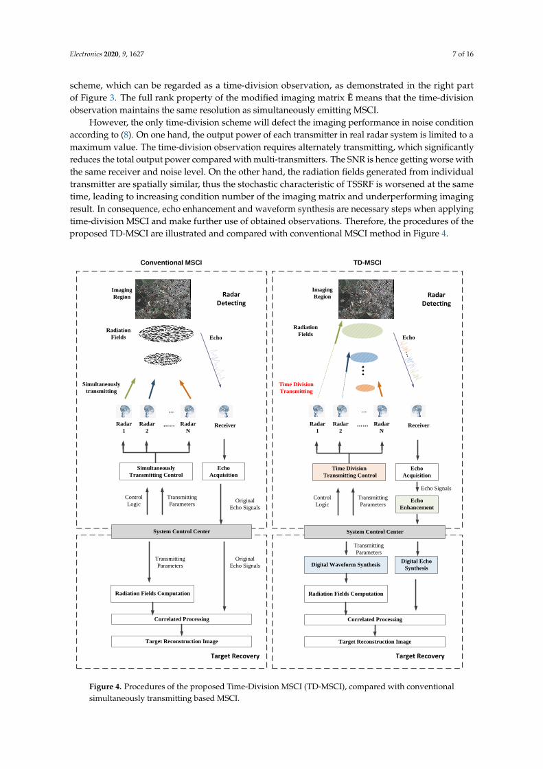
However, the only time-division scheme will defect the imaging performance in noise conditionaccording to (8). On one hand, the output power of each transmitter in real radar system is limited to amaximum value. The time-division observation requires alternately transmitting, which significantlyreduces the total output power compared with multi-transmitters. The SNR is hence getting worse withthe same receiver and noise level. On the other hand, the radiation fields generated from individualtransmitter are spatially similar, thus the stochastic characteristic of TSSRF is worsened at the sametime, leading to increasing condition number of the imaging matrix and underperforming imagingresult. In consequence, echo enhancement and waveform synthesis are necessary steps when applyingtime-division MSCI and make further use of obtained observations. Therefore, the procedures of theproposed TD-MSCI are illustrated and compared with conventional MSCI method in Figure 4.
Conventional MSCI TD-MSCI
Imaging
Region
Radar
1
Radar
2
Radar
NReceiver
Radiation
Fields Echo
System Control Center
……
…
Target Reconstruction Image
Echo
Acquisition
Radiation Fields Computation
Correlated Processing
Imaging
Region
Radiation
FieldsEcho
…
…
…
Simultaneously
Transmitting Control
Simultaneously
transmitting
Time Division
Transmitting
Control
Logic
Transmitting
Parameters
Transmitting
Parameters
Original
Echo Signals
Original
Echo Signals
Radar
1
Radar
2
Radar
NReceiver……
System Control Center
Target Reconstruction Image
Echo
Acquisition
Radiation Fields Computation
Correlated Processing
Time Division
Transmitting Control
Control
Logic
Transmitting
Parameters
Transmitting
Parameters
Echo Signals
Echo
Enhancement
Digital Waveform SynthesisDigital Echo
Synthesis
RadarDetecting
RadarDetecting
Target RecoveryTarget Recovery
Figure 4. Procedures of the proposed Time-Division MSCI (TD-MSCI), compared with conventionalsimultaneously transmitting based MSCI.
Electronics 2020, 9, 1627 8 of 16
3.1. Time Division Observation
A practical time division observation scheme is to directly and physically separate the optimizeddesigns of multiple transmitters, and transmit electromagnetic waves alternately and separatelywith the predefined parameters of each transmitting channel. The time division scheme can also beimplemented via single transmitting channel with changing positions, which significantly decreasesthe system complexity and control logic, and reduces the demand for multichannel synchronizationand the sources of time errors in TD-MSCI.
The superposition principle in electromagnetic field theory guarantees the feasibility of generatingKN radiation fields with k× N observations. Besides the utilized designs, there exists huge numbers ofavailable but unused design resources, such as unused frequencies and waveforms. The unused designresources can enlarge the number K of basic observations under alternately transmitting scheme.
3.2. Echo Enhancement
The SNR is obviously worsened in single transmitting case compared with multiple transmittingscheme. To remedy the defect caused by power coastdown, some preprocessing methods should beapplied to enhance the SNR of the scattering echo. Considering that the echo of each transmitter istime-harmonic, linear phase digital filters with corresponding narrow-band can be utilized.
Another effective way is coherent integration. By reproducing the given design of each transmitterin Q times, the SNR is enhanced to the Q times of its original value after coherent integration [16].
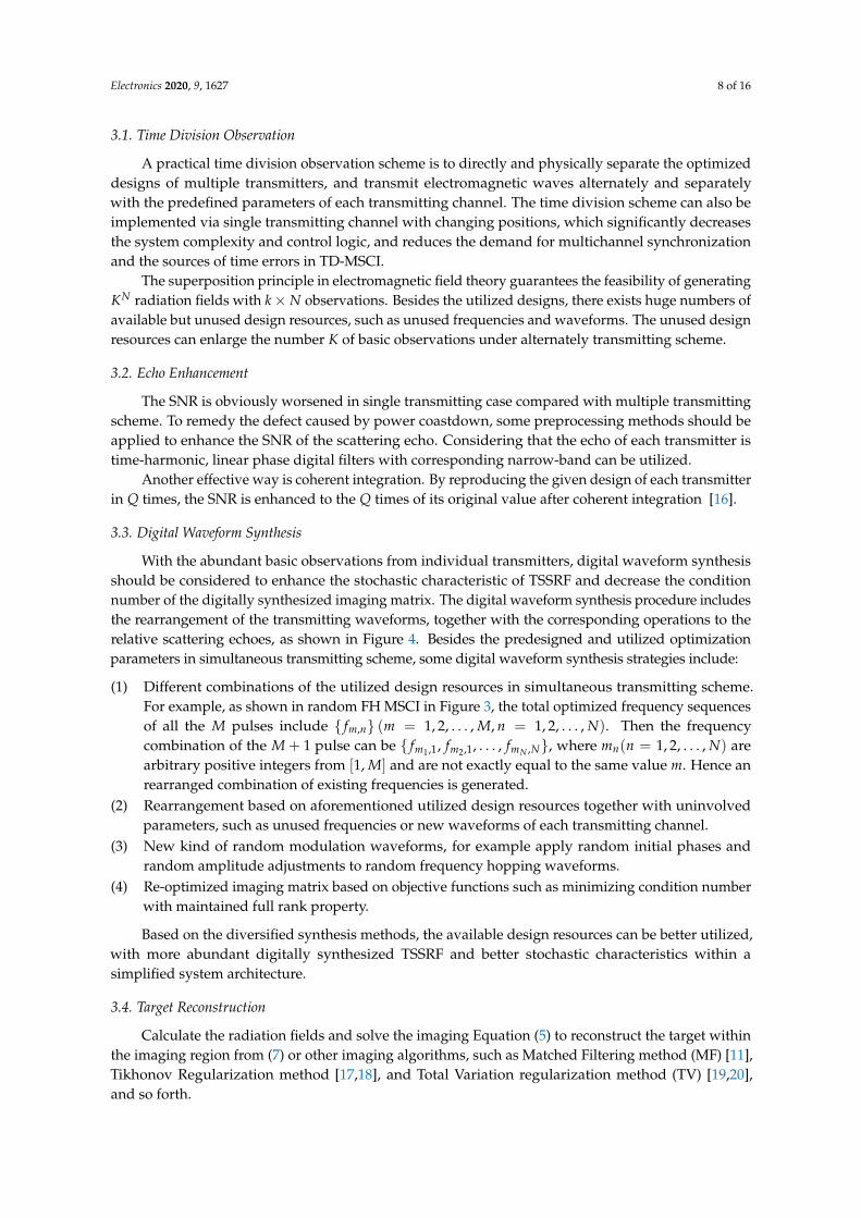
3.3. Digital Waveform Synthesis
With the abundant basic observations from individual transmitters, digital waveform synthesisshould be considered to enhance the stochastic characteristic of TSSRF and decrease the conditionnumber of the digitally synthesized imaging matrix. The digital waveform synthesis procedure includesthe rearrangement of the transmitting waveforms, together with the corresponding operations to therelative scattering echoes, as shown in Figure 4. Besides the predesigned and utilized optimizationparameters in simultaneous transmitting scheme, some digital waveform synthesis strategies include:
(1) Different combinations of the utilized design resources in simultaneous transmitting scheme.For example, as shown in random FH MSCI in Figure 3, the total optimized frequency sequencesof all the M pulses include { fm,n} (m = 1, 2, . . . , M, n = 1, 2, . . . , N). Then the frequencycombination of the M + 1 pulse can be { fm1,1, fm2,1, . . . , fmN ,N}, where mn(n = 1, 2, . . . , N) arearbitrary positive integers from [1, M] and are not exactly equal to the same value m. Hence anrearranged combination of existing frequencies is generated.
(2) Rearrangement based on aforementioned utilized design resources together with uninvolvedparameters, such as unused frequencies or new waveforms of each transmitting channel.
(3) New kind of random modulation waveforms, for example apply random initial phases andrandom amplitude adjustments to random frequency hopping waveforms.
(4) Re-optimized imaging matrix based on objective functions such as minimizing condition numberwith maintained full rank property.
Based on the diversified synthesis methods, the available design resources can be better utilized,with more abundant digitally synthesized TSSRF and better stochastic characteristics within asimplified system architecture.
3.4. Target Reconstruction
Calculate the radiation fields and solve the imaging Equation (5) to reconstruct the target withinthe imaging region from (7) or other imaging algorithms, such as Matched Filtering method (MF) [11],Tikhonov Regularization method [17,18], and Total Variation regularization method (TV) [19,20],and so forth.
Electronics 2020, 9, 1627 9 of 16
4. Results and Discussion
To verify the effectiveness of the proposed TD-MSCI method, numerical imaging experimentswith random frequency hopping waveforms and microwave anechoic chamber imaging experimentare conducted.
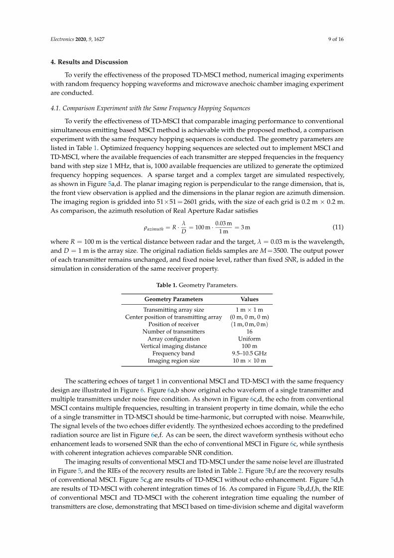
4.1. Comparison Experiment with the Same Frequency Hopping Sequences
To verify the effectiveness of TD-MSCI that comparable imaging performance to conventionalsimultaneous emitting based MSCI method is achievable with the proposed method, a comparisonexperiment with the same frequency hopping sequences is conducted. The geometry parameters arelisted in Table 1. Optimized frequency hopping sequences are selected out to implement MSCI andTD-MSCI, where the available frequencies of each transmitter are stepped frequencies in the frequencyband with step size 1 MHz, that is, 1000 available frequencies are utilized to generate the optimizedfrequency hopping sequences. A sparse target and a complex target are simulated respectively,as shown in Figure 5a,d. The planar imaging region is perpendicular to the range dimension, that is,the front view observation is applied and the dimensions in the planar region are azimuth dimension.The imaging region is gridded into 51×51= 2601 grids, with the size of each grid is 0.2 m × 0.2 m.As comparison, the azimuth resolution of Real Aperture Radar satisfies
ρazimuth = R · λ
D= 100 m · 0.03 m
1 m= 3 m (11)
where R = 100 m is the vertical distance between radar and the target, λ = 0.03 m is the wavelength,and D = 1 m is the array size. The original radiation fields samples are M=3500. The output powerof each transmitter remains unchanged, and fixed noise level, rather than fixed SNR, is added in thesimulation in consideration of the same receiver property.
Table 1. Geometry Parameters.
Geometry Parameters Values
Transmitting array size 1 m × 1 mCenter position of transmitting array (0 m, 0 m, 0 m)
Position of receiver (1 m, 0 m, 0 m)Number of transmitters 16
Array configuration UniformVertical imaging distance 100 m
Frequency band 9.5–10.5 GHzImaging region size 10 m × 10 m
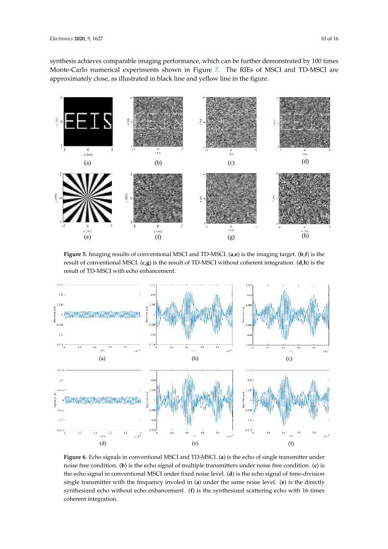
The scattering echoes of target 1 in conventional MSCI and TD-MSCI with the same frequencydesign are illustrated in Figure 6. Figure 6a,b show original echo waveform of a single transmitter andmultiple transmitters under noise free condition. As shown in Figure 6c,d, the echo from conventionalMSCI contains multiple frequencies, resulting in transient property in time domain, while the echoof a single transmitter in TD-MSCI should be time-harmonic, but corrupted with noise. Meanwhile,The signal levels of the two echoes differ evidently. The synthesized echoes according to the predefinedradiation source are list in Figure 6e,f. As can be seen, the direct waveform synthesis without echoenhancement leads to worsened SNR than the echo of conventional MSCI in Figure 6c, while synthesiswith coherent integration achieves comparable SNR condition.
The imaging results of conventional MSCI and TD-MSCI under the same noise level are illustratedin Figure 5, and the RIEs of the recovery results are listed in Table 2. Figure 5b,f are the recovery resultsof conventional MSCI. Figure 5c,g are results of TD-MSCI without echo enhancement. Figure 5d,hare results of TD-MSCI with coherent integration times of 16. As compared in Figure 5b,d,f,h, the RIEof conventional MSCI and TD-MSCI with the coherent integration time equaling the number oftransmitters are close, demonstrating that MSCI based on time-division scheme and digital waveform
Electronics 2020, 9, 1627 10 of 16
synthesis achieves comparable imaging performance, which can be further demonstrated by 100 timesMonte-Carlo numerical experiments shown in Figure 7. The RIEs of MSCI and TD-MSCI areapproximately close, as illustrated in black line and yellow line in the figure.
(a) (b) (c) (d)
(e) (f) (g) (h)
Figure 5. Imaging results of conventional MSCI and TD-MSCI. (a,e) is the imaging target. (b,f) is theresult of conventional MSCI. (c,g) is the result of TD-MSCI without coherent integration. (d,h) is theresult of TD-MSCI with echo enhancement.
(a) (b) (c)
(d) (e) (f)
Figure 6. Echo signals in conventional MSCI and TD-MSCI. (a) is the echo of single transmitter undernoise free condition. (b) is the echo signal of multiple transmitters under noise free condition. (c) isthe echo signal in conventional MSCI under fixed noise level. (d) is the echo signal of time-divisionsingle transmitter with the frequency involed in (a) under the same noise level. (e) is the directlysynthesized echo without echo enhancement. (f) is the synthesized scattering echo with 16 timescoherent integration.
Electronics 2020, 9, 1627 11 of 16
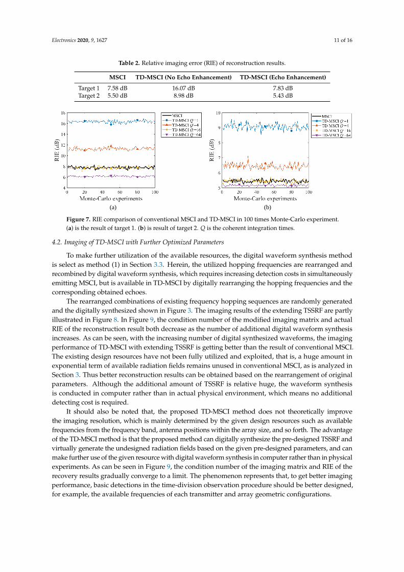
Table 2. Relative imaging error (RIE) of reconstruction results.
MSCI TD-MSCI (No Echo Enhancement) TD-MSCI (Echo Enhancement)
Target 1 7.58 dB 16.07 dB 7.83 dBTarget 2 5.50 dB 8.98 dB 5.43 dB
(a) (b)
Figure 7. RIE comparison of conventional MSCI and TD-MSCI in 100 times Monte-Carlo experiment.(a) is the result of target 1. (b) is result of target 2. Q is the coherent integration times.
4.2. Imaging of TD-MSCI with Further Optimized Parameters
To make further utilization of the available resources, the digital waveform synthesis methodis select as method (1) in Section 3.3. Herein, the utilized hopping frequencies are rearranged andrecombined by digital waveform synthesis, which requires increasing detection costs in simultaneouslyemitting MSCI, but is available in TD-MSCI by digitally rearranging the hopping frequencies and thecorresponding obtained echoes.
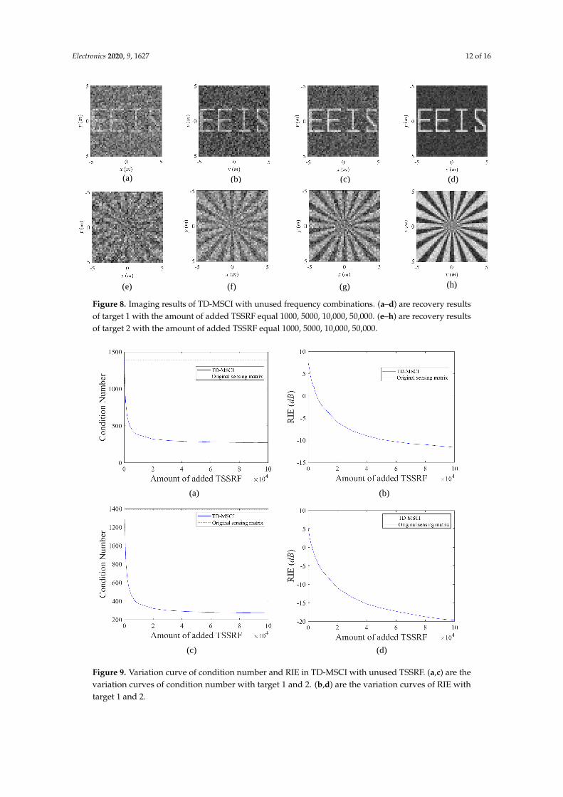
The rearranged combinations of existing frequency hopping sequences are randomly generatedand the digitally synthesized shown in Figure 3. The imaging results of the extending TSSRF are partlyillustrated in Figure 8. In Figure 9, the condition number of the modified imaging matrix and actualRIE of the reconstruction result both decrease as the number of additional digital waveform synthesisincreases. As can be seen, with the increasing number of digital synthesized waveforms, the imagingperformance of TD-MSCI with extending TSSRF is getting better than the result of conventional MSCI.The existing design resources have not been fully utilized and exploited, that is, a huge amount inexponential term of available radiation fields remains unused in conventional MSCI, as is analyzed inSection 3. Thus better reconstruction results can be obtained based on the rearrangement of originalparameters. Although the additional amount of TSSRF is relative huge, the waveform synthesisis conducted in computer rather than in actual physical environment, which means no additionaldetecting cost is required.
It should also be noted that, the proposed TD-MSCI method does not theoretically improvethe imaging resolution, which is mainly determined by the given design resources such as availablefrequencies from the frequency band, antenna positions within the array size, and so forth. The advantageof the TD-MSCI method is that the proposed method can digitally synthesize the pre-designed TSSRF andvirtually generate the undesigned radiation fields based on the given pre-designed parameters, and canmake further use of the given resource with digital waveform synthesis in computer rather than in physicalexperiments. As can be seen in Figure 9, the condition number of the imaging matrix and RIE of therecovery results gradually converge to a limit. The phenomenon represents that, to get better imagingperformance, basic detections in the time-division observation procedure should be better designed,for example, the available frequencies of each transmitter and array geometric configurations.
Electronics 2020, 9, 1627 12 of 16
(a) (b) (c) (d)
(e) (f) (g) (h)
Figure 8. Imaging results of TD-MSCI with unused frequency combinations. (a–d) are recovery resultsof target 1 with the amount of added TSSRF equal 1000, 5000, 10,000, 50,000. (e–h) are recovery resultsof target 2 with the amount of added TSSRF equal 1000, 5000, 10,000, 50,000.
(a) (b)
(c) (d)
Figure 9. Variation curve of condition number and RIE in TD-MSCI with unused TSSRF. (a,c) are thevariation curves of condition number with target 1 and 2. (b,d) are the variation curves of RIE withtarget 1 and 2.
Electronics 2020, 9, 1627 13 of 16
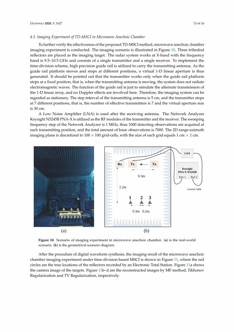
4.3. Imaging Experiment of TD-MSCI in Microwave Anechoic Chamber
To further verify the effectiveness of the proposed TD-MSCI method, microwave anechoic chamberimaging experiment is conducted. The imaging scenario is illustrated in Figure 10. Three trihedralreflectors are placed as the imaging target. The radar system works at X-band with the frequencyband is 9.5–10.5 GHz and consists of a single transmitter and a single receiver. To implement thetime-division scheme, high precision guide rail is utilized to carry the transmitting antenna. As theguide rail platform moves and stops at different positions, a virtual 1-D linear aperture is thusgenerated. It should be pointed out that the transmitter works only when the guide rail platformstops at a fixed position, that is, when the transmitting antenna is moving, the system does not radiateelectromagnetic waves. The function of the guide rail is just to simulate the alternate transmission ofthe 1-D linear array, and no Doppler effects are involved here. Therefore, the imaging system can beregarded as stationary. The step interval of the transmitting antenna is 5 cm, and the transmitter stopsat 7 different positions, that is, the number of effective transmitters is 7 and the virtual aperture sizeis 30 cm.
A Low Noise Amplifier (LNA) is used after the receiving antenna. The Network AnalyzerKeysight N5245B PNA-X is utilized as the RF modules of the transmitter and the receiver. The sweepingfrequency step of the Network Analyzer is 1 MHz, thus 1000 detecting observations are acquired ateach transmitting position, and the total amount of basic observations is 7000. The 2D range-azimuthimaging plane is discretized to 100× 100 grid-cells, with the size of each grid equals 1 cm × 1 cm.
Rx Tx Tx
2.2m
0.3m 0.2m
0.3m
Keysight
PNA-X N5245B
LNA
Port 1 Port 2
coaxial cable
1 2 3
(a) (b)
Figure 10. Scenario of imaging experiment in microwave anechoic chamber. (a) is the real-worldscenario. (b) is the geometrical scenario diagram.
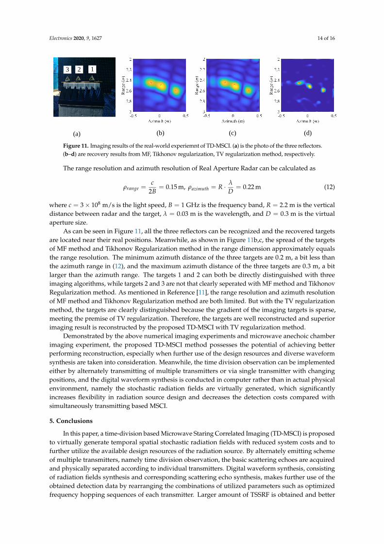
After the procedure of digital waveform synthesis, the imaging result of the microwave anechoicchamber imaging experiment under time-division based MSCI is shown in Figure 11, where the redcircles are the true locations of the reflectors recorded by an Electronic Total Station. Figure 11a showsthe camera image of the targets. Figure 11b–d are the reconstructed images by MF method, TikhonovRegularization and TV Regularization, respectively.
Electronics 2020, 9, 1627 14 of 16
(c)(b)(a) (d)
3 2 1
Figure 11. Imaging results of the real-world experiemnt of TD-MSCI. (a) is the photo of the three reflectors.(b–d) are recovery results from MF, Tikhonov regularization, TV regularization method, respectively.
The range resolution and azimuth resolution of Real Aperture Radar can be calculated as
ρrange =c
2B= 0.15 m, ρazimuth = R · λ
D= 0.22 m (12)
where c = 3× 10⁸ m/s is the light speed, B = 1 GHz is the frequency band, R = 2.2 m is the verticaldistance between radar and the target, λ = 0.03 m is the wavelength, and D = 0.3 m is the virtualaperture size.
As can be seen in Figure 11, all the three reflectors can be recognized and the recovered targetsare located near their real positions. Meanwhile, as shown in Figure 11b,c, the spread of the targetsof MF method and Tikhonov Regularization method in the range dimension approximately equalsthe range resolution. The minimum azimuth distance of the three targets are 0.2 m, a bit less thanthe azimuth range in (12), and the maximum azimuth distance of the three targets are 0.3 m, a bitlarger than the azimuth range. The targets 1 and 2 can both be directly distinguished with threeimaging algorithms, while targets 2 and 3 are not that clearly seperated with MF method and TikhonovRegularization method. As mentioned in Reference [11], the range resolution and azimuth resolutionof MF method and Tikhonov Regularization method are both limited. But with the TV regularizationmethod, the targets are clearly distinguished because the gradient of the imaging targets is sparse,meeting the premise of TV regularization. Therefore, the targets are well reconstructed and superiorimaging result is reconstructed by the proposed TD-MSCI with TV regularization method.
Demonstrated by the above numerical imaging experiments and microwave anechoic chamberimaging experiment, the proposed TD-MSCI method possesses the potential of achieving betterperforming reconstruction, especially when further use of the design resources and diverse waveformsynthesis are taken into consideration. Meanwhile, the time division observation can be implementedeither by alternately transmitting of multiple transmitters or via single transmitter with changingpositions, and the digital waveform synthesis is conducted in computer rather than in actual physicalenvironment, namely the stochastic radiation fields are virtually generated, which significantlyincreases flexibility in radiation source design and decreases the detection costs compared withsimultaneously transmitting based MSCI.
5. Conclusions
In this paper, a time-division based Microwave Staring Correlated Imaging (TD-MSCI) is proposedto virtually generate temporal spatial stochastic radiation fields with reduced system costs and tofurther utilize the available design resources of the radiation source. By alternately emitting schemeof multiple transmitters, namely time division observation, the basic scattering echoes are acquiredand physically separated according to individual transmitters. Digital waveform synthesis, consistingof radiation fields synthesis and corresponding scattering echo synthesis, makes further use of theobtained detection data by rearranging the combinations of utilized parameters such as optimizedfrequency hopping sequences of each transmitter. Larger amount of TSSRF is obtained and better

Electronics 2020, 9, 1627 15 of 16
imaging matrix is achieved without extra physical observations. To make approximate approachto the real SNR situation under multi-transmission, coherent integration is adopted as the echoenhancement strategy to resolve the power coastdown and to enhance the SNR condition of thesynthesized echoes. Numerical imaging experiments demonstrate the effectiveness of TD-MSCI thatthe proposed method achieves comparable performance with simultaneously emitting MSCI under thesame source parameters, and obtains better reconstruction result with further utilization of the utilizeddesign resources. Real-world imaging experiment is conducted with simplified system structure andachieves well-behaved imaging results. Considering that digital waveform synthesis is conducted incomputer rather than in actual physical environment, the proposed TD-MSCI significantly increasesthe design flexibility of the radiation source and decreases the detection costs and system complexity.In future work, considering that the essential of the proposed TD-MSCI is to elaborately designthe basic detection in time-division observation procedure, hence further designs of time-divisionobservations and waveform synthesis methods will be investigated to achieve better imaging results.
Author Contributions: Conceptualization, J.Z. and D.W.; methodology, J.Z.; software, J.Z.; validation, J.Z.; formalanalysis, J.Z.; investigation, J.Z., B.Y. and Z.J.; resources, J.Z.; data curation, J.Z.; writing—original draft preparation,J.Z.; writing—review and editing, J.Z.; visualization, J.Z.; supervision, Y.G. and D.W.; project administration, J.Z.;funding acquisition, Y.G. All authors have read and agreed to the published version of the manuscript.
Funding: This work was funded by National Natural Science Foundation of China under Grant No. 61771446.
Conflicts of Interest: The authors declare no conflict of interest.
Abbreviations
The following abbreviations are used in this manuscript:
MSCI Microwave Staring Correlated ImagingRRS Random Radiation SourceFH Frequency-HoppingTSSRF Temporal-Spatial Stochastic Radiation FieldTD-MSCI Time-Division based Microwave Staring Correlated ImagingRIE Relative Imaging ErrorMF Matched FilteringTV Total Variation
References
1. Pittman, T.B.; Shih, Y.H.; Strekalov, D.V.; Sergienko, A.V. Optical imaging by means of two-photon quantumentanglement. Phys. Rev. A 1995, 52, R3429–R3432. [CrossRef] [PubMed]
2. Erkmen, B.I. Computational ghost imaging for remote sensing. J. Opt. Soc. Am. A 2012, 29, 782–789.[CrossRef] [PubMed]
3. He, X.; Liu, B.; Chai, S.; Wang, D. A novel approach of high spatial-resolution microwave staring imaging.In Proceedings of the Conference Proceedings of 2013 Asia-Pacific Conference on Synthetic Aperture Radar(APSAR), Tsukuba, Japan, 23–27 September 2013; pp. 75–78.
4. Li, D.; Li, X.; Qin, Y.; Cheng, Y.; Wang, H. Radar coincidence imaging: An instantaneous imaging techniquewith stochastic signals. IEEE Trans. Geosci. Remote Sens. 2013, 52, 2261–2277.
5. Li, D.; Li, X.; Cheng, Y.; Qin, Y.; Wang, H. Three dimensional radar coincidence imaging. Prog. Electromagn.Res. M 2013, 33, 223–238. [CrossRef]
6. Zha, G.; Wang, H.; Yang, Z.; Cheng, Y.; Qin, Y. Angular resolution limits for coincidence imaging radarbased on correlation theory. In Proceedings of the Conference 2015 IEEE International Conference on SignalProcessing, Communications and Computing (ICSPCC), Ningbo, China, 19–22 September 2015; pp. 1–4.
7. Zhou, X.; Wang, H.; Cheng, Y.; Qin, Y. Off-grid radar coincidence imaging based on variational sparseBayesian learning. Math. Probl. Eng. 2016, 2016, 1–12. [CrossRef]

Electronics 2020, 9, 1627 16 of 16
8. Zhu, S.; Dong, X.; Zhang, M.; Lu, R.; Li, J.; Chen, X.; Zhang, A. A Super-Resolution ComputationalCoincidence Imaging Method Based on SIMO Radar System. IEEE Geosci. Remote Sens. Lett. 2017, 14,2265–2269. [CrossRef]
9. Zhu, S.; Zhang, A.; Xu, Z.; Dong, X. Radar coincidence imaging with random microwave source.IEEE Antennas Wirel. Propag. Lett. 2015, 14, 1239–1242. [CrossRef]
10. Zhu, S.; He, Y.; Shi, H.; Zhang, A.; Xu, Z.; Dong, X. Mixed mode radar coincidence imaging with hybridexcitation radar array. IEEE Trans. Aerosp. Electron. Syst. 2018, 54, 1589–1604. [CrossRef]
11. Cheng, Y.; Zhou, X.; Xu, X.; Qin, Y.; Wang, H. Radar coincidence imaging with stochastic frequencymodulated array. IEEE J. Sel. Top. Signal Process. 2016, 11, 414–427. [CrossRef]
12. Zhou, X.; Wang, H.; Cheng, Y.; Qin, Y.; Chen, H. Radar Coincidence Imaging for Off-Grid Target UsingFrequency-Hopping Waveforms. Int. J. Antennas Propag. 2016, 2016, 1–16. [CrossRef]
13. Zhou, X.; Wang, H.; Cheng, Y.; Qin, Y.; Chen, H. Waveform Analysis and Optimization for Radar CoincidenceImaging with Modeling Error. Math. Probl. Eng. 2017, 2017, 1–14. [CrossRef]
14. Meng, Q.; Qian, T.; Yuan, B.; Wang, D. Random Radiation Source Optimization Method for MicrowaveStaring Correlated Imaging Based on Temporal-Spatial Relative Distribution Entropy. Prog. Electromagn. Res.2018, 63, 195–206. [CrossRef]
15. Yuan, B.; Guo, Y.; Chen, W.; Wang, D. A Novel Microwave Staring Correlated Radar Imaging Method Basedon Bi-Static Radar System. Sensors 2019, 19, 879. [CrossRef] [PubMed]
16. Skolnik, M.I. Introduction to Radar Systems; McGraw-Hill: New York, NY, USA, 1980; pp. 29–33.17. Tihonov, A.N. Solution of incorrectly formulated problems and the regularization method. Soviet Math.
1963, 4, 1035–1038.18. Hansen, P.C. Analysis of discrete ill-posed problems by means of the L-curve. SIAM Rev. 1992, 34, 561–580.
[CrossRef]19. Strong, D.; Chan, T. Edge-preserving and scale-dependent properties of total variation regularization.
Inverse Probl. 2003, 19, S165. [CrossRef]20. Li, C.; Yin, W.; Jiang, H.; Zhang, Y. An efficient augmented Lagrangian method with applications to total
variation minimization. Comput. Optim. Appl. 2013, 56, 507–530. [CrossRef]
c© 2020 by the authors. Licensee MDPI, Basel, Switzerland. This article is an open accessarticle distributed under the terms and conditions of the Creative Commons Attribution(CC BY) license (http://creativecommons.org/licenses/by/4.0/).