Embed Size (px)
Citation preview

microwave photonic systems
Microwave Photonic Systems, Inc., 1155 Phoenixville Pike, Unit 106, West Chester, PA 19380
Toll Free: 888-868-8967, Phone: 610-344-7676, Fax: 610-344-7110, e-mail: [email protected]
In-Building Repeater Systems
In-Building Repeater Systems
IDAS-340 Land Mobile RadioIDAS-800 Emergency and Public Safety
2 0 1 2 C A T A L O G
For More Information:Call us toll-free at 888-868-8967 or Email [email protected]
MPS leverages RF and Microwave component design knowledge and fiber optic systems integrationexpertise to develop in-building repeaters targeted towards the Public Safety and Mobile Subscriber mar-kets. Systems include 400 to 900 MHz Trunked Radio and Public Safety, as well as, PCS, LTE and WiMax.

microwave photonic systemsin-building repeater systems
IDAS-340/LMR
IDAS-340/LMR: 378 to 512 MHz Radio (LMR) Repeater System
Expanded In-Building Coverage for 378 to 512 MHz Land Mobile Radio (LMR) Systems for Critical Communications and First Responder Network Traffic Over Distributed An-tenna Systems The IDAS-340/LMR, is a Fiber Optic “In-Building” Transmission System, which provides a novel RF design approach to achieve the operational requirement of providing expanded continuity of critical communications network traffic. The IDAS-340/LMR consists of a suite of hardware elements including a Bi-Directional Amplifier (IDAS-340/BDA), a Central Fiber Donor Unit (IDAS-340/CFDU) and a Remote Fiber Unit(s) (IDAS-340/RFU).
The IDAS-340/LMR utilizes proprietary and field proven Radio Frequency and Fiber Optic technology to transmit and receive the desired spectrum of 378 to 512 MHz trunking ra-dio signal traffic over a Hybrid Fiber Coax structured Distributed Antenna System (DAS). This approach, provides the ability to securely route and distribute LMR signal traffic to mounted antenna locations throughout the communications network infrastructure beyond the limitations of convential coaxial based deployment schemes. The IDAS-340/LMR can be integrated into architectures requiring Point-To-Point or Point-To-Multi-Point topologies sup-porting user augmentations found within Government Facilities, Hospitals, Schools, Parking Garages, and Public Transit Facilites. The IDAS-340/LMR complements MPS’s offering of IDAS systems such as the IDAS-800 Public Safety and the ISAT-7700 Emergency Satellite Telephone System. MPS is a full service design, integration, and test certification contractor offering full specturm in-building distributed antenna solutions.
Information: Call us toll-free at 888-868-8967 or email [email protected]
Microwave Photonic Systems, Inc.1155 Phoenixville Pike, Unit 106, West Chester, PA 19380, Toll-Free: 888-868-8967Phone: 610-344-7676, Fax: 610-344-7110, E-mail: [email protected], Internet: b2bphotonics.com
100204 CAGE 1A9M1
Market Applications
• Network Operation Centers
• Emergency Response Centers
• Schools & Libraries
• Courthouses & Prisons
• Airports, Rail Road Stations, Bus Terminals
• Hospitals & Police Stations
Features & Options
• Enhanced Signal Filtering
• All Passive Hardware Supports AWS, LTE, iDEN & WiMAX Technologies
• Battery Back Up Options Available
• Front Panel Display of System Status
• Remote Status Monitor and Control
• 2 Year Warranty
Deployment Schemes
• Distributed Antenna Systems
-- Point to Point : Single or Multi-User
-- Point to Multi-Point: Single or Multi-User
Packaging Options
• Wall Mount
• Rack Mount
• Indoor or Outdoor Roof Top
• Portable Transit Case for Emergency Response Scenarios

IDAS-340/LMR
IDAS-340/LMR: 378 to 512 MHz Radio (LMR) Repeater System
Microwave Photonic Systems, Inc.1155 Phoenixville Pike, Unit 106, West Chester, PA 19380, Toll-Free: 888-868-8967Phone: 610-344-7676, Fax: 610-344-7110, E-mail: [email protected], Internet: b2bphotonics.com
100204 CAGE 1A9M1
in-building repeater systems
SpecificationsOptical Parameters
Optical Wavelength:Optical Output Power:Optical Connector:Max Optical Reflections:Fiber Optic Cable Type:Optical Link Budget:
RF ParametersPrimary Frequency Range (Option A):Primary Frequency Range (Option B):Additional Frequency Ranges:Rejection:Gain:Gain Flatness:Noise Figure:Attenuation Range:Power Output @ 1dB Compression:
Output Power ALC Set:
Output Composite Power:
Output 3rd Order Intercept:
Impedance (Input / Output):VSWR (Input / Output):RF Connector (Input / Output):
Additional SpecificationsAC PWR Input:DC Input Voltage:Unit Power Consumption (AC/DV):AC Receptacle:Storage Temperature: Operating Temperature:Status & Control:Battery Backup:Dimensions & Weight: Wall Mount
1310 nm , 1550 nm or CWDM available4 mW (typical)FC/APC , SC/APC, or E2000 APC< - 55 dBmSingle Mode, 9/125 umup to 10 dBo
378 to 430 MHz (UHF Lower)450 to 512 MHz (UHF Upper)Customer Specified VHF or Other Radio Bands+35 dBc (typical) @ +/- 4MHz from Passband80 dB (min)+/- 1.5 dB (max)5.0 dB (max) ; 4.5 dB (typical)0 - 30 dB in 2dB incrementsUplink: +34.0 dBm (typical)Downlink: +44.0 dBm (typical)Uplink: +27 dBm (typical)Downlink: +37 dBm (typical)Uplink: +27 dBm (typical)Downlink: +37 dBm (typical)Uplink: +47 dBm (typical) , 2 tones @ +20 dBm Downlink: +55 dBm (typical) , 2 tones @ +31 dBm50 Ohms1.5:1N-Female
Auto Ranging, 120 VAC, 60 Hz, Single Phase+24 to +27 VDC, -48 VDC Optional< 100 VAIEC 320-20°C to +80°C -10°C to +50°CRS-232, RS-485 or Ethernet Options2 , 4 and 8 Hour Options Available14” x 18” x 6” & 25 lbs (US)
Note*RF Specifications listed are typical. Actual values shall be optimized for in-building coverage.
IDAS-340/CFDUCentral Fiber Donor Unit
IDAS-340/RFURemote Fiber Unit
IDAS-340/BDABi-Directional Amplifier

IDAS-340/LMR
IDAS-340/LMR: 378 to 512 MHz Radio (LMR) Repeater System
Microwave Photonic Systems, Inc.1155 Phoenixville Pike, Unit 106, West Chester, PA 19380, Toll-Free: 888-868-8967Phone: 610-344-7676, Fax: 610-344-7110, E-mail: [email protected], Internet: b2bphotonics.com
100204 CAGE 1A9M1
in-building repeater systems
Microwave Photonic
MPSMPS
Functional Block Diagram: Hybrid Fiber Coax Distributed Antenna System (example)
Depolyed Site Overlay: Hybrid Fiber Coax Distributed Antenna System (example)
microwave photonic systems
IDAS-800/SMR
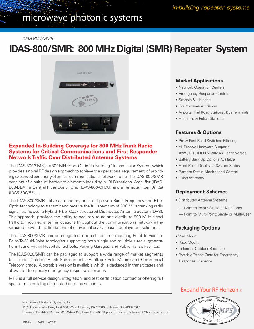
IDAS-800/SMR: 800 MHz Digital (SMR) Repeater System
Expanded In-Building Coverage for 800 MHz Trunk Radio Systems for Critical Communications and First Responder Network Traffic Over Distributed Antenna Systems The IDAS-800/SMR, is a 800 MHz Fiber Optic “In-Building” Transmission System, which provides a novel RF design approach to achieve the operational requirement of provid-ing expanded continuity of critical communications network traffic. The IDAS-800/SMR consists of a suite of hardware elements including a Bi-Directional Amplifier (IDAS-800/BDA), a Central Fiber Donor Unit (IDAS-800/CFDU) and a Remote Fiber Unit(s) (IDAS-800/RFU).
The IDAS-800/SMR utilizes proprietary and field proven Radio Frequency and Fiber Optic technology to transmit and receive the full spectrum of 800 MHz trunking radio signal traffic over a Hybrid Fiber Coax structured Distributed Antenna System (DAS). This approach, provides the ability to securely route and distribute 800 MHz signal traffic to mounted antenna locations throughout the communications network infra-structure beyond the limitations of convential coaxial based deployment schemes.
The IDAS-800/SMR can be integrated into architectures requiring Point-To-Point or Point-To-Multi-Point topologies supporting both single and multiple user augmenta-tions found within Hospitals, Schools, Parking Garages, and Public Transit Facilites.
The IDAS-800/SMR can be packaged to support a wide range of market segments to include: Outdoor Harsh Environments (Rooftop / Pole Mount) and Commercial Telecom grade. A portable version is available which is packaged in transit cases and allows for temporary emergency response scenarios.
MPS is a full service design, integration, and test certification contractor offering full specturm in-building distributed antenna solutions.
Market Applications• Network Operation Centers
• Emergency Response Centers
• Schools & Libraries
• Courthouses & Prisons
• Airports, Rail Road Stations, Bus Terminals
• Hospitals & Police Stations
Features & Options
• Pre & Post Band Switched Filtering
• All Passive Hardware Supports
AWS, LTE, iDEN & WiMAX Technologies
• Battery Back Up Options Available
• Front Panel Display of System Status
• Remote Status Monitor and Control
• 1 Year Warranty
Deployment Schemes
• Distributed Antenna Systems
---- Point to Point : Single or Multi-User
---- Point to Multi-Point: Single or Multi-User
Packaging Options
• Wall Mount
• Rack Mount
• Indoor or Outdoor Roof Top
• Portable Transit Case for Emergency
Response Scenarios
Microwave Photonic Systems, Inc.1155 Phoenixville Pike, Unit 106, West Chester, PA 19380, Toll-Free: 888-868-8967Phone: 610-344-7676, Fax: 610-344-7110, E-mail: [email protected], Internet: b2bphotonics.com
100421 CAGE 1A9M1
Microwave Photonic
MPSMPS
Expand Your RF Horizon ©
in-building repeater systems

IDAS-800/SMR
800 MHz Fiber Optic In-Building Repeater System
Microwave Photonic Systems, Inc.1155 Phoenixville Pike, Unit 106, West Chester, PA 19380, Toll-Free: 888-868-8967Phone: 610-344-7676, Fax: 610-344-7110, E-mail: [email protected], Internet: b2bphotonics.com
100421 CAGE 1A9M1
Optical Parameters :
Optical WavelengthOptical Output PowerOptical Connector Max Optical ReflectionsFiber Optic Cable TypeOptical Link Budget
RF Parameters:
Downlink Frequency RangeUplink Frequency RangeRejectionGainGain FlatnessNoise FigureAttenuation Range Power Output @ 1dB Compression
Output Power ALC Set
Output Composite Power
Output 3rd Order Intercept
Impedance (Input / Output)VSWR (Input / Output)RF Connector (Input / Output)
Additional Specifications:
AC PWR InputDC Input VoltageUnit Power Consumption (AC/DV)AC Receptacle Storage Temperature Operating TemperatureStatus & ControlBattery Backup Dimensions & Weight: Wall Mount
1310 nm , 1550 nm or CWDM available4 mW (typical)FC/APC , SC/APC, or E2000 APC< - 55 dBmSingle Mode, 9/125 umup to 10 dBo
851-869 MHz ; [ 851-861 MHz Post Re-Band ]806-824 MHz ; [ 806-816 MHz Post Re-Band ]+35 dBc (typical) @ +/- 4MHz from Passband80 dB (min)+/- 1.5 dB (max)5.0 dB (max) ; 4.5 dB (typical)0 - 30 dB in 2dB incrementsUplink: +34.0 dBm (typical)Downlink: +44.0 dBm (typical)Uplink: +27 dBm (typical)Downlink: +37 dBm (typical)Uplink: +27 dBm (typical)Downlink: +37 dBm (typical)Uplink: +47 dBm (typical) , 2 tones @ +20 dBm Downlink: +55 dBm (typical) , 2 tones @ +31 dBm50 Ohms1.5:1N-Female
Auto Ranging, 120 VAC, 60 Hz, Single Phase+24 to +27 VDC, -48 VDC Optional< 100 VAIEC 320-20°C to +80°C -10°C to +50°CRS-232, RS-485 or Ethernet Options2 , 4 and 8 Hour Options Available14” x 18” x 6” & 25 lbs (US) (Note 2)
System Specifications
IDAS-800/BDA
Bi-Directional Amplifier
IDAS-800/RFU
Remote Fiber Unit
IDAS-800/CFDU
Central Fiber Donor Unt
in-building repeater systems
Expand Your RF Horizon ©
Microwave Photonic
MPSMPS

in-building repeater systems
IDAS-800/SMR
800 MHz In-Building Repeater System
Microwave Photonic Systems, Inc.1155 Phoenixville Pike, Unit 106, West Chester, PA 19380, Toll-Free: 888-868-8967Phone: 610-344-7676, Fax: 610-344-7110, E-mail: [email protected], Internet: b2bphotonics.com
100204 CAGE 1A9M1
Microwave Photonic
MPSMPS
Functional Block Diagram: Hybrid Fiber Coax Distributed Antenna System
Expand Your RF Horizon ©
Depolyed Site Overlay: Hybrid Fiber Coax Distributed Antenna System