Embed Size (px)
Citation preview

microwave photonic systems
Microwave Photonic Systems, Inc., 1155 Phoenixville Pike, Unit 106, West Chester, PA 19380
Toll Free: 888-868-8967, Phone: 610-344-7676, Fax: 610-344-7110, e-mail: [email protected]
Optical Link Systems
Optical Link Systems
OFW-400 IFBand Fiber Optic Interfacility LinkOFW-800 Forward Path Optical LinkOFW-1217 X Band Interfacility LinkOFW-1900 PCS Wireless Distribution SystemOFW-2320 UHF Fiber Optic Interfaclity LinkOFW-3427 L-Band Fiber Teleport SystemOFW-1328 GPS Distribution SystemOFW-3478 GPS Inmarsat Photonic Antenna LinkOFW-5800 Shipboard GPS Photonic Antenna LinkOFW-6700 DualL/XBand Fiber Optic Transmission SystemOFW-7300 MIL-SATCOML-Band Interfacility Link
2 0 1 2 C A T A L O G
For More Information:Call us toll-free at 888-868-8967 or Email [email protected]
MPS offers highly integrated systems solutions that call upon the entire product offering of MPS. Thesesystems are designed for major communication networks or earth terminals requiring highly reliable sys-tems with the ability to provide Ethernet Links, Redundant Switching, Frequency Timing and Reference,as well as comprehensive Monitor and Control capabilities.

microwave photonic systemsoptical link systems
OFW-400
Intermediate Frequency (IF) Fiber Optic Intermediate Frequency (IF) Fiber Optic Interfacility Link (IFL) System
The principle hardware for long-haul transmission of IF signals in the frequency range of 5 MHz to 300 MHz over singlemode fi ber optic cableThe OFW-400 Intermediate Frequency (IF) Fiber Optic Interfacility Link (IFL) System is the principle hardware for long-haul transmission of IF signals in the frequency range of 5 MHz to 300 MHz over singlemode fi ber optic cable. The standard transmitter and receiver con-fi guration provides transmission distances up to 50 km. An optional extended-range con-fi guration can be specifi ed that increases the link range to 80 km. The system’s optical con-version process is functionally independent of the IF carrier’s data modulation format. The links have low noise and high dynamic range characteristics, a wide operating temperature range and provide turnkey installation.
The system provides status monitoring through the use of an onboard processor that com-municates with a host computer over a RS-232 I/O interface. The I/O parameters include laser bias current, optical receive power, internal temperature and alarm monitoring. In ad-dition, an optional Low Noise Amplifi er (LNA) or integrated Bias-T for remote LNA powering may be specifi ed. Also, the system may be specifi ed with an extended frequency range of 5 MHz to 500 MHz. Finally, the OFW-400 when specifi ed with the 75 ohm input/output impedance option provides a highperformance, cost-effective solution for CATV Return Path signal distribution in Hybrid Fiber/Coax Networks.
Information: Call us toll-free at 888-868-8967 or email [email protected]
Microwave Photonic Systems, Inc.1155 Phoenixville Pike, Unit 106, West Chester, PA 19380, Toll-Free: 888-868-8967Phone: 610-344-7676, Fax: 610-344-7110, E-mail: [email protected], Internet: b2bphotonics.com
100204 CAGE 1A9M1
Applications
• CATV Return Path Link
• Interfacility Link Remoting
• Frequency Reference Distribution
• SATCOM Uplink & Downlink Remoting
• IF Distribution, 70 MHz/140 MHz
• HF & VHF Signal Transmission
Features
• CWDM Compatible
• Wide Bandwidth, 5 MHz to 500 MHz
• High Dynamic Range
• Low Noise RF Front-end (opt)
• LNB Powering (opt)
• 80 km Extended Range (opt)
• RS-232 or RS-485 Data Port (opt)
• 1 Year Full, 2 Year Limited Warranty

OFW-400
Intermediate Frequency (IF) Fiber Optic Interfacility Link (IFL) System
Microwave Photonic Systems, Inc.1155 Phoenixville Pike, Unit 106, West Chester, PA 19380, Toll-Free: 888-868-8967Phone: 610-344-7676, Fax: 610-344-7110, E-mail: [email protected], Internet: b2bphotonics.com
100204 CAGE 1A9M1
optical link systems
Microwave Photonic
MPSMPS
1310 nm ± 2 nm or CWDM Bands or 1550 nm ± 2 nm Class 3A+3 dBm ± 0.5 dBm36 dB @ full specs0.06 W/A
Specifi cations
Operating Wavelength:
Laser Diode:Output Power:Allowed Backrefl ection (max):E/O Diff. Eff. (min):
Optical
Power Supply, AC Autoranging:
Power Supply, DC Autoranging (opt):AC Recepticle:Optical Input:
RF Output Connector:Operating Temperature:Storage Temperature:Local Alarm:
Optical Power Monitor:Remote Alarms:
85 VAC -264 VAC, 47 Hz to 440 Hz, Single Phase
-48 VCD to +48 VCDIEC 320FC/APC, SC/APC, AVIM APC or User
Specifi edSMA(f), 50 ohm or F(f), 75 ohm-40° C to +71° C-40° C to +85° CLED - Optical Power FailureLED - Line Power On1 V/m W ± 10%Open Collector and RS-232 or RS-485 Interface
General
RF Channel
Modulation Bandwidth:
Flatness (max):VSWR (max):1 dB Comp. Level (min):Input IP-3 (min) @ 2x+3 dBm:Input Damage Level:RF Link Gain (typ):Noise Figure (max):
5.0 MHz to 300.0 MHz or 5.0 MHz to 500.0 MHz (opt)± 1.0 dB2.0:120.0 dBm*34.0 dBm*+27.0 dBm*+0.0 dB @ 1.0 dB Optical Loss*35 dB @ 1.0 dB Optical Loss* * Note: Overall link performance as measured from transmitter IF
input to receiver IF output.

microwave photonic systemsoptical link systems
MPS-800TX
Forward Path Optical Transmitter(used with MPS-850RX)
Designed to provide transmission of Telephony, High Speed Internet and analog signals in the 40 MHz – 860 MHz range over broadband fi ber optic networksThe OFW-800TX Forward Path Optical Transmitter is designed to provide transmission of Telephony, High Speed Internet and analog signals in the 40 MHz – 860 MHz range over broadband fi ber optic networks from a single head-end point or hub to multiple distribution nodes within the Hybrid Fiber/Coax (HFC) network. The OFW-800TX Forward Path Optical Transmitter is offered in a standard 19 inch, 1U rack mountable unit or in confi gurations such that it may be placed in a Head-End cabinet, a DTX Chassis or an Outside Plant optical node. The robust system design has a high MTBF with an internal system architecture allowing for components to be easily expanded in order to meet the changing needs of the HFC net-work. The OFW-800TX Forward Path Optical Transmitter can operate at industry standard wavelengths required for operation and successful integration to all commercial CWDM or DWDM systems. The OFW-800TX Forward Path Optical Transmitter can be integrated with other MPS products to provide fl exible system confi gurations and expansion. The OFW-800TX Forward Path Optical Transmitter, when coupled with the OFW-800RX Forward Path Optical Receiver, the MPS-2300 Optical Splitter and the MPS-2700 Wavelength Division Multiplexer (WDM) provides a highly reliable forward path link in HFC networks. In addi-tion, both the OFW-800TX Forward Path Optical Transmitter and OFW-800RX Return Path Optical Transmitter can support the simultaneous transmission of network management information over an auxiliary data channel facilitating system diagnostic reporting, network monitoring and a means of seamless redundancy switching. The OFW-800TX and OFW-800RX are offered in optional 1 GHz confi guration to allow for expanded data capability necessitated by industry progression to providing multi services.
Information: Call us toll-free at 888-868-8967 or email [email protected]
Microwave Photonic Systems, Inc.1155 Phoenixville Pike, Unit 106, West Chester, PA 19380, Toll-Free: 888-868-8967Phone: 610-344-7676, Fax: 610-344-7110, E-mail: [email protected], Internet: b2bphotonics.com
100204 CAGE 1A9M1
Applications
• CATV Return Path Link
• Interfacility Link Remoting
• Frequency Reference Distribution
• SATCOM Uplink & Downlink Remoting
• IF Distribution, 70 MHz/140 MHz
• HF & VHF Signal Transmission
Features
• Compatible with FC and SC Connectors
• Housed in Low Profi le 19” Rack Mountable Drawer
• Accomodates up to Five Independent Receivers per 1U Enclosure
• Low Noise RF Front-end (opt)
• RF Test Point: -20 dB
• Auxiliary Data Channel per Receiver (opt)
• 1 Year Full, 2 Year Limited Warranty

MPS-800TX
Forward Path Optical Transmitter (used with MPS-850RX)
Microwave Photonic Systems, Inc.1155 Phoenixville Pike, Unit 106, West Chester, PA 19380, Toll-Free: 888-868-8967Phone: 610-344-7676, Fax: 610-344-7110, E-mail: [email protected], Internet: b2bphotonics.com
100204 CAGE 1A9M1
optical link systems
Microwave Photonic
MPSMPS
1310.0 nm ± 20 nm6 mW (min)40 MHz to 860 MHz± 1.0 dB35.0 dBmV (max)-14.0 dB (min)75 ohm> 52 dB (Ch BW = 5 MHz)> 60 dB (OMI = 3.7%, 80 Ch Loading)> 65 dB (OMI = 3.7%, 80 Ch Loading)Optical Power Failure, Power SupplyOptical Power0.0° C to 60.0° C50 W15 lbs. (max)19”(w) x 12”(l) x 1.75”(h)120 VAC, 60 Hz
Specifi cations
Operating Wavelength:Output Power:Bandwidth:Flatness:Input Level:Return Loss:RF Impedance:C/N:CSO:CTB:Alarms & LEDS:Monitors:Operating Temperature:Power Consumption:Weight:Dimensions:Line Power:
Optical/General
microwave photonic systemsoptical link systems
MPS-850RX
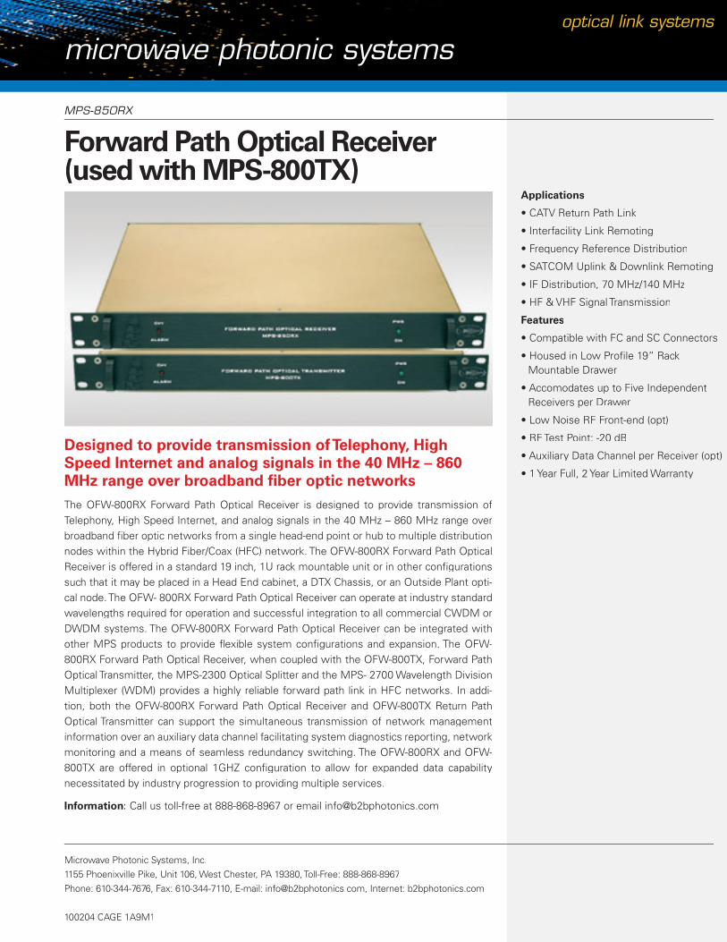
Forward Path Optical Receiver(used with MPS-800TX)
Designed to provide transmission of Telephony, High Speed Internet and analog signals in the 40 MHz – 860 MHz range over broadband fi ber optic networksThe OFW-800RX Forward Path Optical Receiver is designed to provide transmission of Telephony, High Speed Internet, and analog signals in the 40 MHz – 860 MHz range over broadband fi ber optic networks from a single head-end point or hub to multiple distribution nodes within the Hybrid Fiber/Coax (HFC) network. The OFW-800RX Forward Path Optical Receiver is offered in a standard 19 inch, 1U rack mountable unit or in other confi gurations such that it may be placed in a Head End cabinet, a DTX Chassis, or an Outside Plant opti-cal node. The OFW- 800RX Forward Path Optical Receiver can operate at industry standard wavelengths required for operation and successful integration to all commercial CWDM or DWDM systems. The OFW-800RX Forward Path Optical Receiver can be integrated with other MPS products to provide fl exible system confi gurations and expansion. The OFW-800RX Forward Path Optical Receiver, when coupled with the OFW-800TX, Forward Path Optical Transmitter, the MPS-2300 Optical Splitter and the MPS- 2700 Wavelength Division Multiplexer (WDM) provides a highly reliable forward path link in HFC networks. In addi-tion, both the OFW-800RX Forward Path Optical Receiver and OFW-800TX Return Path Optical Transmitter can support the simultaneous transmission of network management information over an auxiliary data channel facilitating system diagnostics reporting, network monitoring and a means of seamless redundancy switching. The OFW-800RX and OFW-800TX are offered in optional 1GHZ confi guration to allow for expanded data capability necessitated by industry progression to providing multiple services.
Information: Call us toll-free at 888-868-8967 or email [email protected]
Microwave Photonic Systems, Inc.1155 Phoenixville Pike, Unit 106, West Chester, PA 19380, Toll-Free: 888-868-8967Phone: 610-344-7676, Fax: 610-344-7110, E-mail: [email protected], Internet: b2bphotonics.com
100204 CAGE 1A9M1
Applications
• CATV Return Path Link
• Interfacility Link Remoting
• Frequency Reference Distribution
• SATCOM Uplink & Downlink Remoting
• IF Distribution, 70 MHz/140 MHz
• HF & VHF Signal Transmission
Features
• Compatible with FC and SC Connectors
• Housed in Low Profi le 19” Rack Mountable Drawer
• Accomodates up to Five Independent Receivers per Drawer
• Low Noise RF Front-end (opt)
• RF Test Point: -20 dB
• Auxiliary Data Channel per Receiver (opt)
• 1 Year Full, 2 Year Limited Warranty

MPS-850RX
Forward Path Optical Receiver (used with MPS-800TX)
Microwave Photonic Systems, Inc.1155 Phoenixville Pike, Unit 106, West Chester, PA 19380, Toll-Free: 888-868-8967Phone: 610-344-7676, Fax: 610-344-7110, E-mail: [email protected], Internet: b2bphotonics.com
100204 CAGE 1A9M1
optical link systems
Microwave Photonic
MPSMPS
1290.0 nm to 1600.0 nm3.0 dBm (max)40 MHz to 860 MHz± 1.0 dB<-15.0 dB (min)75 ohm32 dBmV (max) (OMI = 3.7%)> 60 dB (OMI = 3.7%, Opt Pwr = -3 dB, Ch BW = 5 MHz)> 65 dB (OMI = 3.7%, Opt Pwr = +3 dBm, 80 Ch Loading)> 65 dB (OMI = 3.7%, Opt Pwr = +3 dBm, 80 Ch Loading)Optical Power Failure, Power SupplyOptical Power0.0° C to 60.0° C25 W14 lbs. (max)19”(w) x 12”(l) x 1.75”(h)120 VAC, 60 Hz
Specifi cations
Operating Wavelength:Input Optical Power:RF Bandwidth:Flatness:Return Loss:RF Impedance:Output Level:C/N:CSO:CTB:Alarms & LEDS:Monitors:Operating Temperature:Power Consumption:Weight:Dimensions:Line Power:
RF/Optical

microwave photonic systemsoptical link systems
OFW-1217
Fiber Optic Antenna Link (FOAL)
Designed to simultaneously transport up to four separate X-Band SATCOM uplink and downlink signals between an earth station facility and a remotely located antenna siteThe OFW-1217L Inter Facility Link (IFL) is an analog fi ber optic modem designed to si-multaneously transport up to four separate X-Band SATCOM uplink and downlink signals between an earth station facility and a remotely located antenna site via a multi strand optical cable. The IFL is packaged in two, 19” rack mountable equipment chassis’ that serve as the interface units between the uplink and downlink segments of the XBand SATCOM system. The IFL uplink channel accepts X-Band input signals (7.9 to 8.4 GHz) from the earth station facility equipment while the downlink channel accepts X-Band input signals (7.25 to 7.75 GHz) from the antenna site equipment. The IFL data link operates over a primary and an auxiliary data channel at a data rate of 38.4 Kbps. The IFL rack unit provides an RS-485 data expansion port for additional IFL rack units to be cascaded to the primary unit without degradation to any of the IFL System functions. The IFL optical transmitter and receiver plug-in modules are capable of supporting future applications of WDM technology and are confi gurable to support Ku-Band satellite operations by exchanging the X-Band optical receiver plug-in module, Model # 10350A, with the Ku-Band optical receiver plugin module, Model # 10350B. The IFL can also support mixed mode satellite operations; that is, simultaneous X-Band and Ku-Band operations. The IFL is delivered with a Windows based RS-485, Monitor and Control System (MCS), capable of digital or analog signal monitoring, performing manual or automatic control sequences, and initiating alarms. The IFL System has capability of automatic, emergency, and manual switch over, as well as the ability to ex-ercise all IFL System sub-component modules. These prognostic features allow the system operator to maintain auxiliary subcomponent module operational readiness by identifying faults in modules before they are requested as an essential back up thereby increasing system availability.
Information: Call us toll-free at 888-868-8967 or email [email protected]
Microwave Photonic Systems, Inc.1155 Phoenixville Pike, Unit 106, West Chester, PA 19380, Toll-Free: 888-868-8967Phone: 610-344-7676, Fax: 610-344-7110, E-mail: [email protected], Internet: b2bphotonics.com
100204 CAGE 1A9M1
Features
• X-Band Uplink and Downlink
• Low Noise
• High Link Dynamic Range
• Imbedded Software Control
• 1U Rack Mountable Formfactor
• Custom Confi gurations are Available
• 1 Year Full, 2 Year Limited Warranty
OFW-1217
Fiber Optic Antenna Link (FOAL)
Microwave Photonic Systems, Inc.1155 Phoenixville Pike, Unit 106, West Chester, PA 19380, Toll-Free: 888-868-8967Phone: 610-344-7676, Fax: 610-344-7110, E-mail: [email protected], Internet: b2bphotonics.com
100204 CAGE 1A9M1
optical link systems
Microwave Photonic
MPSMPS
1550 nm ± 6 nm>7.0 dBm<-1550 dBm/HzFC/APCSingle mode (9/125) micronAntenna Unit: -28°C to +65°CReceiver Unit: 0°C to +50°C, -40°C to +71°C, Antenna & Receiver UnitMil-STD-167Mil-S-901D
Specifi cations
Wavelength Range:Output Opt Power:Rel Intensity Noise:Conn type:Fiber:Operating Temperature:
Storage Temperature:Vibration:Shock:
Optical Parameters
RF Parameters
Frequency Range:Amplitude Flatness:Input/Output Impedance:Input/Output VSWR:Input 1 dB Comp.:Max. RF Input Power:Input Third Order (IP3):Eq. Input Noise (EIN):Noise Figure (NF)*:Spur Free Dynamic Range:SNR @ 1 dB Comp.:
0.1 to 18.0 GHz± 1.0 dB (max.) @ 7.0 to 9.0 GHz50 ohms1.35:1 (max.) @ 7.0 to 9.0 GHz>+13.0 dBm @ 7.0 to 9.0 GHz>24.0 dBm @ 7.0 to 9.0 GHz>+27.0 dBm @ 7.0 to 9.0 GHz<-126.0 dBm/Hz @ 7.0 to 9.0 GHz<48.0 dB @ 7.0 to 9.0 GHz>+102.0 dB-Hz(2/3) @ 7.0 to 9.0 GHz>+141.0 dB @ 7.0 to 9.0 GHz, 1Hz BW
(NF)* Note = +174 dBm/Hz + EIN dBm/Hz
microwave photonic systemsoptical link systems
OFW-1900
PCS Wireless Antenna Distribution SystemPCS Wireless Antenna Distribution System
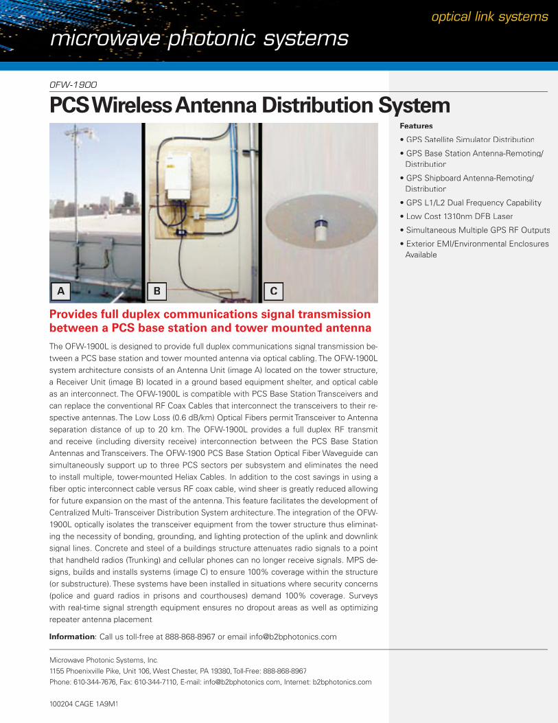
Provides full duplex communications signal transmission between a PCS base station and tower mounted antennaThe OFW-1900L is designed to provide full duplex communications signal transmission be-tween a PCS base station and tower mounted antenna via optical cabling. The OFW-1900L system architecture consists of an Antenna Unit (image A) located on the tower structure, a Receiver Unit (image B) located in a ground based equipment shelter, and optical cable as an interconnect. The OFW-1900L is compatible with PCS Base Station Transceivers and can replace the conventional RF Coax Cables that interconnect the transceivers to their re-spective antennas. The Low Loss (0.6 dB/km) Optical Fibers permit Transceiver to Antenna separation distance of up to 20 km. The OFW-1900L provides a full duplex RF transmit and receive (including diversity receive) interconnection between the PCS Base Station Antennas and Transceivers. The OFW-1900 PCS Base Station Optical Fiber Waveguide can simultaneously support up to three PCS sectors per subsystem and eliminates the need to install multiple, tower-mounted Heliax Cables. In addition to the cost savings in using a fi ber optic interconnect cable versus RF coax cable, wind sheer is greatly reduced allowing for future expansion on the mast of the antenna. This feature facilitates the development of Centralized Multi- Transceiver Distribution System architecture. The integration of the OFW-1900L optically isolates the transceiver equipment from the tower structure thus eliminat-ing the necessity of bonding, grounding, and lighting protection of the uplink and downlink signal lines. Concrete and steel of a buildings structure attenuates radio signals to a point that handheld radios (Trunking) and cellular phones can no longer receive signals. MPS de-signs, builds and installs systems (image C) to ensure 100% coverage within the structure (or substructure). These systems have been installed in situations where security concerns (police and guard radios in prisons and courthouses) demand 100% coverage. Surveys with real-time signal strength equipment ensures no dropout areas as well as optimizing repeater antenna placement.
Information: Call us toll-free at 888-868-8967 or email [email protected]
Microwave Photonic Systems, Inc.1155 Phoenixville Pike, Unit 106, West Chester, PA 19380, Toll-Free: 888-868-8967Phone: 610-344-7676, Fax: 610-344-7110, E-mail: [email protected], Internet: b2bphotonics.com
100204 CAGE 1A9M1
Features
• GPS Satellite Simulator Distribution
• GPS Base Station Antenna-Remoting/Distribution
• GPS Shipboard Antenna-Remoting/Distribution
• GPS L1/L2 Dual Frequency Capability
• Low Cost 1310nm DFB Laser
• Simultaneous Multiple GPS RF Outputs
• Exterior EMI/Environmental Enclosures Available
A B C

OFW-1900
PCS Wireless Antenna Distribution System
Microwave Photonic Systems, Inc.1155 Phoenixville Pike, Unit 106, West Chester, PA 19380, Toll-Free: 888-868-8967Phone: 610-344-7676, Fax: 610-344-7110, E-mail: [email protected], Internet: b2bphotonics.com
100204 CAGE 1A9M1
optical link systems
1970.0 to 1975.0 MHz 1890.0 to 1895.0 MHz .5:1 (max) TX to RX 100 dB (min) 0.1 dB (max)
Specifi cations
TX Band:RX / DIVERSITY RX:VSWR:Isolation:Insertion Loss:
Duplexer - Diversity Receive
Downlink (TX)Frequency Range:Gain (G):Gain Flatness:Output 1dB Compression:Output Third Order:Input/Output VSWR:
1970.0 to 1975.0 MHz 36.0 dB (typ) ± 0.25 dB (max)45.0 dBm (min) 54.0 dBm (min) 1.5:1 (max)
Uplink (RX)
Frequency Range:Gain (G):Gain Flatness:Output 1dB Compression:Output Third Order:Input/Output VSWR:
1970.0 to 1975.0 MHz 36.0 dB (typ) ± 0.25 dB (max)45.0 dBm (min) 54.0 dBm (min) 1.5:1 (max)
BTS RF Parameters
1300 nm ± 15 nm3.0 dBm/CH (typ)
Wavelength:Output Power:
Downlink & Uplink
Optical Parameters
1300 nm ± 15 nm3.0 dBm/CH (typ)
Operating Temperature:Storage Temperature:
Antenna Unit
Environmental
1300 nm ± 15 nm3.0 dBm/CH (typ)
Operating Temperature:Storage Temperature:
Receiver Unit
Analog and BinaryAnalog and Binary
Antenna Unit:Receiver Unit:
Downlink & Uplink
Monitor/Control
15.0 dBi (typ) 44.5 dBm (typ) 4 (max) .25 MHz (max) 7.0 dB (min) 4.5 miles (min)
TX Antenna Gain (G):EIRP per Channel:Channel Capacity:RF Bandwidth per Channel: HPA P1dB Backoff (BO):Coverage Radius:
Downlink
BTS Parameters
Uplink
RX Antenna Gain (G):Noise Figure (NF):“Minimum” Received Signal Power: * Path Loss = 114.0 dB @ 4.5 miles “Maximum” Received Signal Power: * Path Loss = 80.5 dB @ 0.1 miles Bit Energy per Noise (Eb/N0):
15.0 dBi (typ) 5.0 dB (max) -100.0 dBm (min)
-57.0 dBm (max)
7.0 dB (min)
-1.0 dBi (max)23.0 dBm (max)10.7 dB (max)7.0 dB (min)
Antenna Gain (G):Transmit Power:Noise Figure:Bit Energy per Noise (Eb/N0):
Uplink/Downlink
Mobile Unit

OFW-1900
PCS Wireless Antenna Distribution System
Microwave Photonic Systems, Inc.1155 Phoenixville Pike, Unit 106, West Chester, PA 19380, Toll-Free: 888-868-8967Phone: 610-344-7676, Fax: 610-344-7110, E-mail: [email protected], Internet: b2bphotonics.com
100204 CAGE 1A9M1
optical link systems
Microwave Photonic
MPSMPS
Coverage Map / Antenna Placement Scheme
When MPS does an RF Distribution system, a Complete analysis of the site is performed to get real-time values of propagation, not imaginary “Oh-we assumed it would work” values! This approach entails quite a bit of on site equipment and analysis but we guarantee no “Dead Spots “ for our fi nished installation.
Below are two examples of a coverage map and a system antenna placement scheme with typical values within a steel and concrete multi level structure.

microwave photonic systemsoptical link systems
OFW-2320TRX
UHF Fiber Optic Interfacility Link (IFL) SystemUHF Fiber Optic Interfacility Link (IFL) System
Designed to provide full duplex signal transmission be-tween a UHF Ground Station and its transmit/receive antenna complexThe OFW-2320TRX UHF Fiber Optic Interfacility Link (IFL) System is the principle hardware for long-haul transmission of UHF signals in the frequency range of 225 MHz to 400 MHz over singlemode fi ber optic cable. The OFW-2320TRX is designed to provide full duplex sig-nal transmission between a UHF Ground Station and its transmit/receive antenna complex with as much as 50 km of optical cabling. The OFW-2320TRX system architecture consists of a Remote Unit located at the antenna complex such that it is optically interconnected to a Local Unit at the ground station. The OFW-2320TRX is compatible with UHF SATCOM Transceivers and can replace the conventional RF Coax Cables that interconnect the trans-ceivers to their respective antennas. The system function is independent of the RF carrier’s data modulation format. The links have low noise and high dynamic range characteristics, a wide operating temperature range and provide turnkey installation. The system provides status monitoring through the use of an onboard processor that communicates with a host computer over a RS-232 or RS-485 I/O interface.
A typical antenna installation confi guration would resemble an architecture where the OFW-2320TRX remote unit is installed such that it is interconnected to the Antenna via an uplink/downlink duplexer. Specifi cally, the uplink optical channel connects to the Power Am-plifi er (PA), the downlink optical channel connects to the Low Noise Amplifi er (LNA). Simi-larly, the ground station installation confi guration would resemble an architecture where the OFW-2320TRX uplink and downlink optical channels are mated to the radio SATCOMM transceivers. With the addition of an optional WDM module will enable the system to have bi-directional uplink/downlink transmission over a single fi ber optic cable.
Information: Call us toll-free at 888-868-8967 or email [email protected]
Microwave Photonic Systems, Inc.1155 Phoenixville Pike, Unit 106, West Chester, PA 19380, Toll-Free: 888-868-8967Phone: 610-344-7676, Fax: 610-344-7110, E-mail: [email protected], Internet: b2bphotonics.com
100204 CAGE 1A9M1
Applications
• Interfacility Link Remoting
• SATCOM Uplink & Downlink Remoting
• UHF Distribution, 225 MHz to 400 MHz
Features
• CWDM Compatible
• High Dynamic Range
• Low Noise RF Front-end
• LNA Powering (opt)
• 80 km Extended Range (opt)
• RS-232 or RS-485 Data Port (opt)
• 1 Year Full, 2 Year Limited Warranty

OFW-2320TRX
UHF Fiber Optic Interfacility Link (IFL) System
Microwave Photonic Systems, Inc.1155 Phoenixville Pike, Unit 106, West Chester, PA 19380, Toll-Free: 888-868-8967Phone: 610-344-7676, Fax: 610-344-7110, E-mail: [email protected], Internet: b2bphotonics.com
100204 CAGE 1A9M1
optical link systems
Microwave Photonic
MPSMPS
1310 nm ± 2 nm or CWDM Bands or 1550 nm ± 2 nm Class 3A+3 dBm ± 0.5 dBm36 dB @ full specs0.06 W/A
Specifi cations
Operating Wavelength:
Laser Diode:Output Power:Allowed Backrefl ection (max):E/O Diff. Eff. (min):
Optical
Power Supply:Optical Connector:
RF Connector:Operating Temperature:Storage Temperature:Local Alarm:
Optical Power Monitor:Remote Alarms:
Dimensions:
+8 VDC to +24 VDC @ 500 mAFC/APC, SC/APC, AVIM APC or User
Specifi edSMA(f), 50 ohm or F(f), 75 ohm-40° C to +71° C-40° C to +85° CLED - Optical Power FailureLED - Line Power On1 V/m W ± 10%Open Collector and RS-232 or RS-485 Interface5.6” x 6.0” x 1.35”
General
RF Channel Uplink/Downlink
Modulation Bandwidth:Flatness (max):VSWR (max):1 dB Comp. Level (min):Input IP-3 (min) @ 2x+3 dBm:Input Damage Level:RF Link Gain (typ):Noise Figure (max):
100 MHz to 2500 MHz± 2.0 dB2.0:115.0 dBm*26.0 dBm*+27.0 dBm*+0.0 dB @ 1.0 dB Optical Loss*35 dB @ 1.0 dB Optical Loss*
* Note: Overall link performance as measured RF input to RF output.

microwave photonic systemsoptical link systems
OFW-3427
L-Band Fiber Optic Interfacility Link (IFL) SystemL-Band Fiber Optic Interfacility Link (IFL) System
The principle hardware for long-haul transmission of RF signals in the frequency range of 800 MHz to 2250 MHz over singlemode fi ber optic cableThe OFW-3427 L-Band Fiber Optic IFL System is the principle hardware for long-haul trans-mission of RF signals in the frequency range of 800 MHz to 2250 MHz over singlemode fi ber optic cable. The standard transmitter and receiver confi guration provides transmission distances up to 50 km. An optional extended-range confi guration can be specifi ed that increases the link range to 80 km. The system’s optical conversion process is functionally independent of the RF carrier’s data modulation format. The links have low noise and high dynamic range characteristics, a wide operating temperature range and provide turnkey installation.
The system provides status monitoring through the use of an onboard processor that com-municates with a host computer over a RS-232 I/O interface. The I/O parameters include laser bias current, optical receive power, internal temperature and alarm monitoring. In addition, an optional integrated Bias-T for LNB powering may be specifi ed. The OFW-3427 provides a high-performance, cost-effective solution for transporting L-Band signals over single mode fi ber.
Information: Call us toll-free at 888-868-8967 or email [email protected]
Microwave Photonic Systems, Inc.1155 Phoenixville Pike, Unit 106, West Chester, PA 19380, Toll-Free: 888-868-8967Phone: 610-344-7676, Fax: 610-344-7110, E-mail: [email protected], Internet: b2bphotonics.com
100204 CAGE 1A9M1
Applications
• Wideband RF Transmission
• Antenna Remoting
• Trunking Radio
• L - Band SATCOM
• GPS / Wireless / PCS
Features
• CWDM Compatible
• Wide Bandwidth, 800 MHz to 2250 MHz
• High Dynamic Range
• Low Noise RF Front-end
• LNB Powering (opt)
• 80 km Extended Range (opt)
• RS-232 or RS-485 Data Port (opt)
• 1 Year Full, 2 Year Limited Warranty

OFW-3427
L-Band Fiber Optic Interfacility Link (IFL) System
Microwave Photonic Systems, Inc.1155 Phoenixville Pike, Unit 106, West Chester, PA 19380, Toll-Free: 888-868-8967Phone: 610-344-7676, Fax: 610-344-7110, E-mail: [email protected], Internet: b2bphotonics.com
100204 CAGE 1A9M1
optical link systems
Microwave Photonic
MPSMPS
75 ohm50 ohm40.0 dB @ RF Input Level = dBmV50.0 dB @ RF Input Level = 20 dBmV25.0 dB @ RF Input Level = 10 dBmV38.0 dB @ RF Input Level = 20 dBmV21.0 dB (min)1.0 dB (min)± 2.0 dB+34.0 dBmV+50.0 dBmV @ 0.0 dB Optical Loss+57.0 dBmV @ -12 dB Optical Loss+48.0 dBmV15.0 dB @ 0 dB Opt. Loss, 27 MHz BW32.0 dB @ 12 dB Opt. Loss, 27 MHz BW
Specifi cations
I/O ImpedanceF-Conn Version:
SMA-Conn Version:Carrier-to-Noise Ratio*:
Carrier-to-Noise Ratio**:
Link RF Gain (@ 0dB Opt. Loss):Link RF Gain (@ 12dB Opt. Loss):RF Gain Variation Over Temp.:Composite 1 dB Compression Point:Second Order Intercept Point (IP2):Second Order Intercept Point (IP2):Third Order Intercept Point (IP3):Noise Figure (@ 0 dB Opt. Loss)Noise Figure (@ 12 dB Opt. Loss):
Optical/Electrical
Power Supply, AC Autoranging:Power Supply, DC Autoranging (opt):AC Recepticle:Optical Input:RF Output Connector:Operating Temperature:Storage Temperature:Local Alarm:
Optical Power Monitor:Remote Alarms:Dimensions:
85 VAC -264 VAC, 47 Hz to 440 Hz, Single Phase-48 VCD to +48 VCDIEC 320FC/APC, SC/APC, AVIM APC or User Specifi edSMA(f), 50 ohm or F(f), 75 ohm-40° C to +71° C-40° C to +85° CLED - Optical Power FailureLED - Line Power On1 V/m W ± 10%Open Collector and RS-232 or RS-485 Interface 19”(w) x 14’(l) x 1.75”(h)
General

microwave photonic systemsoptical link systems
OFW-1328
GPS Distribution System
Designed to receive low level GPS satellite signals from various GPS Antennas or simulatorsThe OFW-1328 “L-Band” Fiber Optic Distribution System consists of four subassemblies consisting of a GPS Antenna, a Transmitter Module, and Receiver Module and a fi ber optic interconnection cable. The OFW-1328 “L-Band” Fiber Optic Distribution System is designed to receive low level GPS satellite signals from various GPS Antennas or simulators. The system detects and converts the optical carriers to an RF signal capable of driving the front end of multiple GPS receivers. The OFW-1328 “L-Band” Fiber Optic Distribution System transmitter can generate three Amplitude Modulated (AM) optical carriers, handle Simulta-neous Multiple GPS RF outputs, and feed multiple GPS receivers within the system archi-tecture. The receiver transmitter is powered by Low Cost 1310nm DFB laser and distributes all signals via a multi-fi ber single mode optical cable. The OFW-1328 “L-Band” Fiber Optic Distribution System receiver is capable of handling GPS L1/L2 Dual Frequencies and can be separated from the GPS signal source by as much as ten kilometers. The OFW-1328 “L-Band” Fiber Optic Distribution System can be delivered in a Exterior EMI/Environmental Enclosures to meet strictest survivability demands. The OFW-1328 “L-Band” Fiber Optic Distribution System can be customized in numerous distribution applications such as a GPS Satellite Simulator Distribution, GPS Base Station Antenna-Remoting/Distribution, or a GPS Shipboard Antenna-Remoting/Distribution. Contact MPS directly for specifi c design applica-tions and technical specifi cations.
Information: Call us toll-free at 888-868-8967 or email [email protected]
Microwave Photonic Systems, Inc.1155 Phoenixville Pike, Unit 106, West Chester, PA 19380, Toll-Free: 888-868-8967Phone: 610-344-7676, Fax: 610-344-7110, E-mail: [email protected], Internet: b2bphotonics.com
100204 CAGE 1A9M1
Features
• GPS Satellite Simulator Distribution
• GPS Base Station Antenna Remoting/Distribution
• GPS Shipboard Antenna Remoting/Distribution
• GPS L1/L2 Dual Frequency Capability
• Low Cost 1310 nm DFB Laser
• Simultaneous Multiple GPS RF Outputs
• Exterior EMI/Environmental Enclosures Available

OFW-1328
GPS Distribution System
Microwave Photonic Systems, Inc.1155 Phoenixville Pike, Unit 106, West Chester, PA 19380, Toll-Free: 888-868-8967Phone: 610-344-7676, Fax: 610-344-7110, E-mail: [email protected], Internet: b2bphotonics.com
100204 CAGE 1A9M1
optical link systems
Microwave Photonic
MPSMPS
1310 nm ± 30 nm0.1 to 0.2 mW/mA3 dBm (min) per output port± 15%< 10.0 Mhz (typ)3 dBm (max)
Specifi cations
Wavelength:DC Modulation Gain:Laser Output Power:Power Stability vs. Temp.:Spectral Width (FWHM-no RF):Photodiode Power:
Optical Parameters
Frequency Range:
Small Signal Gain:Output Third Order Intercept:Input/Output VSWR:In-Band Burnout Protection:
(L1) 1575.4 MHz ±10.23 MHz(L2) 1227.6 MHz ±10.23 MHz0.0 dB ± 1.0 dB, or User Defi ned-35.0 dBm (min)2:1 (max)1.0 W, CW
General
Physical/Electrical
AC Power:Dimensions/Weight Antenna Module: Transmitter Module: Receiver Module:
120V, 5A, 60 Hz
12” x 14” x 6” / 25 lbs.18” x 19” x 5.25” / 20 lbs.18” x 19” x 3.5” / 20 lbs.

microwave photonic systemsoptical link systems
OFW-3478
GPS/Inmarsat Fiber Optic Antenna LinkGPS/Inmarsat Fiber Optic Antenna Link
Designed to perform E/O and O/E conversion of RF satel-lite downlink signals over a range of 1.0 GHz to 2.0 GHzThe OFW-3478 GPS/Inmarsat Photonic Antenna Link is designed to perform E/O and O/E conversion of RF satellite downlink signals over a range of 1.0 GHz to 2.0 GHz. Specifi cally, the link can accept simultaneous RF inputs from both a GPS antenna and an Inmarsat an-tenna. The RF/optical signals can then be transported between the antenna headend and the radio-processing center over an optical fi ber cable up to distances of 50 km. An optional long-haul DFB laser can be specifi ed that increases the link range to 80 km. The system’s optical conversion process is functionally independent of the RF carrier’s data modulation format. In addition, an optional integrated Bias-T for GPS and Inmarsat LNA powering may be specifi ed. The system can be tailored for a variety of custom L-Band SATCOM applica-tions.
The OFW-3478 system provides end-to-end status monitoring of it’s head-end and radio processing center units through the use of an imbedded software controlled onboard pro-cessor that can communicate with a M & C host computer over a RS-232 I/O interface. The I/O parameters include GPS and Inmarsat LNA current, GPS and Inmarsat laser bias cur-rent, GPS and Inmarsat optical receive power, internal temperature and alarm monitoring. The OFW-3478 provides a high-performance, costeffective solution for transporting L-Band signals over single mode fi ber.
Information: Call us toll-free at 888-868-8967 or email [email protected]
Microwave Photonic Systems, Inc.1155 Phoenixville Pike, Unit 106, West Chester, PA 19380, Toll-Free: 888-868-8967Phone: 610-344-7676, Fax: 610-344-7110, E-mail: [email protected], Internet: b2bphotonics.com
100204 CAGE 1A9M1
Applications
• Satellite Signal Generator Distribution
• Antenna Remoting
• L-Band SATCOM
• Telemetry
• Time & Freq. Reference Distribution
Features
• CWDM Compatible
• GPS L1/L2 Dual Frequency Capability
• High Link Dynamic Range
• Status Monitoring of Key System Comp. over RS-232
• Imbedded Software Control
• LNA Powering (opt)
• Custom Confi gurations are Available
• 1 Year Full, 2 Year Limited Warranty

OFW-3478
GPS/Inmarsat Fiber Optic Antenna Link
Microwave Photonic Systems, Inc.1155 Phoenixville Pike, Unit 106, West Chester, PA 19380, Toll-Free: 888-868-8967Phone: 610-344-7676, Fax: 610-344-7110, E-mail: [email protected], Internet: b2bphotonics.com
100204 CAGE 1A9M1
optical link systems
Microwave Photonic
MPSMPS
-20.0 dB to 38.0 dB, adjus table range3.0 dB to 40.0 dB, adjus table range2:0:1 (max)>-20.0 dBm>100.0 dB Hz2/3>15.0 dBm1310 nm, 1550 nm or CWDM
Specifi cations
RF Gain:RF Noise:VSWR In/Out:P1dB:SFDR:Optical Loss Budget:Optical Wavelength:
GPS
Power Supply, AC Autoranging:
Power Supply, DC Autoranging (opt):AC Recepticle:Optical Input:
RF Output Connector:Operating Temperature:Storage Temperature:Local Alarm:
Optical Power Monitor:Remote Alarms:
Dimensions:
85 VAC -264 VAC, 47 Hz to 440 Hz, Single Phase
-48 VCD to +48 VCDIEC 320FC/APC, SC/APC, AVIM APC or User
Specifi edSMA(f), 50 ohm or F(f), 75 ohm-40° C to +71° C-40° C to +85° CLED - Optical Power FailureLED - Line Power On1 V/m W ± 10%Open Collector and RS-232 or RS-485 Interface 19”(w) x 14”(l) x 1.75”(h)
General
Inmarsat
RF Gain:RF Noise:VSWR In/Out:P1dB:SFDR:Optical Loss Budget:Optical Wavelength:
-20.0 dB to 38.0 dB, adjus table range3.0 dB to 40.0 dB, adjus table range2:0:1 (max)>-20.0 dBm>100.0 dB Hz2/3>15.0 dBm1310 nm, 1550 nm or CWDM

microwave photonic systemsoptical link systems
OFW-5800
Fiber Optic Antenna Link (FOAL)
Confi gured to receive L1 and L2 GPS RF signals, generate a RF intensity modulated optical carrier and transmit the optical carrier to the receiver module via a shipboard fi ber optic cableThe OFW-5800L Fiber Optic Antenna Link (FOAL) consists of an antenna module, located on the topside mast structure, and a receiver module, located in the below deck naviga-tion space (IC/GYRO Room). OFW-5800L Fiber Optic Antenna Link (FOAL) is confi gured to receive L1 and L2 GPS RF signals, generate a RF intensity modulated optical carrier and transmit the optical carrier to the receiver module via a shipboard fi ber optic cable. OFW-5800L Fiber Optic Antenna Link (FOAL) detects and converts the optical carrier to the GPS RF signals and distributes the GPS signals to the GVRC. When confi gured as a Dual FOAL Subsystem, the OFW-5800L Fiber Optic Antenna Link (FOAL) consists of two independent FOALs each interconnected through a corresponding NAVSSI/GVRC RTS. In this confi gura-tion the OFW-5800L Fiber Optic Antenna link (FOAL) is capable of meeting the antenna subsystem requirements of the NAVSSI/GVRC DUAL RTS architecture.
Information: Call us toll-free at 888-868-8967 or email [email protected]
Microwave Photonic Systems, Inc.1155 Phoenixville Pike, Unit 106, West Chester, PA 19380, Toll-Free: 888-868-8967Phone: 610-344-7676, Fax: 610-344-7110, E-mail: [email protected], Internet: b2bphotonics.com
100204 CAGE 1A9M1
Features
• Utilizes Commercial-Off-the-Shelf (COTS) Hardware
• Preserves Dual FOAL Subsystem Performance Specs
• Eliminates Topside FO & AC Power IC Box
• Retains Existing Military FRPA-GP Enclosure
• Integrates Mil. Multi-Channel Opt. Connector into FRPA-GP
• Supports Various FO Cable Interconnection Architectures
• Compatible with Existing FOAL Receiver Drawer ICD
OFW-5800
Fiber Optic Antenna Link (FOAL)
Microwave Photonic Systems, Inc.1155 Phoenixville Pike, Unit 106, West Chester, PA 19380, Toll-Free: 888-868-8967Phone: 610-344-7676, Fax: 610-344-7110, E-mail: [email protected], Internet: b2bphotonics.com
100204 CAGE 1A9M1
optical link systems
Microwave Photonic
MPSMPS
1310 nm ± 15 nm± 2 nm3.0 dBm/CH (typ)0.03 W/A>0.85 AW
-28° C to +65° C0° C to +50° C
-40° C to +71° C-40° C to +71° CMil-STD-167Mil-S-901D
Specifi cations
Wavelength:Linewidth:Output Power:E/O EFF:Responsivity:Operating Temperature Antenna Unit: Receiver Unit:Storage Temperature: Antenna Unit: Receiver Unit:Vibration:Shock:
Optical Performance
Gain:Center Freqs.:Out of Band Rej.
Noise Figure:Input/Output VSWR:Spur Free Dynamic Range:Input Protection:
Max. RF Input:
21.0 dB (min), 35.0 dB (max)L1, 1575.42 MHz and L2, 1227.6 MHz-3.0 dB BW - 40 MHz (max)-40.0 dB BW - 140 MHz (max)-70.0 dB BW - 245 MHz (max)4.0 dB (max)2.0:1 (max)95.0 dB Hz 2/3 (typ)<2.0 GHz, 350 W Peak, 10 micro sec PW, 0.1% DC<2.0 GHz, 400 W Peak, 10 micro sec PW, 0.1% DC30 dBm, CW
RF Performance*
* Note: Values measured from RF Input to RF Output.

microwave photonic systemsoptical link systems
OFW-6700TX / OFW-6700RX
Dual L / X Band Fiber Optic Transmission System
Dynamic Configurability of Uplink/Downlink Transmission Paths for MIL SATCOM L-Band or X-Band Terminals.The OFW-6700 is a high performance RF/ Fiber Optic Transmission system designed for L-Band and X-Band SATCOM Uplink & Downlink RF transmission applications. The OFW-6700 functions as Dual Band Fiber Optic Interfacility Link when the OFW-6700TX is paired with the OFW-6700RX and interconnected using single mode fiber optic cable. The OFW-6700TX and OFW-6700RX have been designed to provide maximum flexibility for the sys-tems operator. The OFW-6700TX and OFW-6700RX are both configured with integrated digital attenuators. The L-Band transmission path is configured with variable gain adjust-ment capability on the receiver, while the X-Band transmission path is configured with variable gain adjustment elements on both the transmit and receive stages. The benefit of this variable configuration is that is allows the OFW-6700 to meet both the operational requirements of an Uplink (UL) or Downlink (DL) transmission path within MIL-SATCOM terminals.
The integrated microprocessor provides monitor and control of the system performance parameters allowing the operator to dynamically execute signal path adjustments. Adjust-ments are achieved through the use of front panel input keys or via the RS-485 communica-tions port and the local host computer. The integrated 19” x 1RU chassis design provides front panel VFD display for immediate presentation of operational status and critical param-eters such as gain stage values, internal temperature, received optical power, power supply voltages and system alarm status.
Information: Call us toll-free at 888-868-8967 or email [email protected]
Microwave Photonic Systems, Inc.1155 Phoenixville Pike, Unit 106, West Chester, PA 19380, Toll-Free: 888-868-8967Phone: 610-344-7676, Fax: 610-344-7110, E-mail: [email protected], Internet: b2bphotonics.com
100204 CAGE 1A9M1
Applications
• Antenna Remoting
• X Band SATCOM Transmission
• L Band SATCOM Transmission
Features
• L-Band Uplink or Downlink
• X-Band Uplink or Downlink
• High Spur Free Dynamic Range
• Dynamic Gain Adjustment
• VFD Panel Display
• Front Panel Adjustment Keys
• Status Monitoring: RS-485

OFW-6700TX / OFW-6700RX
Dual Band Fiber Optic Ifl Transmission SystemL-Band: 950 MHz to 2 GHz / X-band: 7 to 9 GHz
Microwave Photonic Systems, Inc.1155 Phoenixville Pike, Unit 106, West Chester, PA 19380, Toll-Free: 888-868-8967Phone: 610-344-7676, Fax: 610-344-7110, E-mail: [email protected], Internet: b2bphotonics.com
100204 CAGE 1A9M1
optical link systems
SpecificationsOptical:
Operating Wavelength:Optical Output Level (min): E/O Diff. Eff. (min):Line Width (3 dB):Side Mode Supression (typ):
Uplink Channel: Frequency:Flatness (typ.): VSWR Input/Output (max): 1 dB Comp. Level (min):Output IP-3 (min):RF Link Gain (min): Noise Figure (max): RF Input Power (max):
Downlink Channel: Frequency:Flatness (typ.): VSWR Input/Output (max): 1 dB Comp. Level (min):Output IP-3 (min):RF Link Gain (min): Noise Figure (max): RF Input Power (max):
General:Power Supply Options:
Optical / RF Connector: Operating/Storage Temp.: Local Alarm:Remote Alarms: Dimensions:
(1): Link performance measured when configured as an IFL with 2 dBo.
1310 nm +5.0 dBm 0.1 W/A 10 MHz 45.0 dB
L-Band950 MHz to 2.0 GHz ±0.75 dB over any 500 MHz Bandwidth 1.5:1 20.0 dBm(1) (Input) 30.0 dBm(1) -10.0 dB +/- 1.0 dB(1) 58.0 dB (1) + 10 dBm L-Band950 MHz to 2.0 GHz ±0.75 dB over any 500 MHz Bandwidth 1.5:1 20.0 dBm(1) (Input) 30.0 dBm(1) -10.0 dB +/- 1.0 dB(1) 58.0 dB (1) +18 dBm
Internal Power Supply Universal AC, ExternalDual Power Supply Universal AC, 15 VDC FC/APC & SMA (f), 50 ohm 0.0°C to +50°C & -20°C to +70°C LED: Bit Fault & Optical Power Failure RS-485 Interface 19” x 1RU Rack Chassis
X-Band7.9 GHz to 8.4 GHz ±0.75 dB over any 500 MHz Bandwidth 1.8:1 15.0 dBm(1) (Output) 27.0 dBm(1) 0.0 dB +/- 1.0 dB(1) 46.0 dB (1) + 12 dBm X-Band7.25 GHz to 7.75 GHz ±0.75 dB over any 500 MHz Bandwidth 1.8:1 0.0 dBm(1) (Output)12.0 dBm(1) 0.0 dB +/- 1.0 dB(1) 32.0 dB (1) -3.0 dBm

OFW-6700TX / OFW-6700RX
Dual Band Fiber Optic Ifl Transmission SystemL-Band: 950 MHz to 2 GHz / X-band: 7 to 9 GHz
Microwave Photonic Systems, Inc.1155 Phoenixville Pike, Unit 106, West Chester, PA 19380, Toll-Free: 888-868-8967Phone: 610-344-7676, Fax: 610-344-7110, E-mail: [email protected], Internet: b2bphotonics.com
100204 CAGE 1A9M1
optical link systems
Microwave Photonic
MPSMPS
Functional Block Diagram:

microwave photonic systemsoptical link systems
OFW-7300-IFL
MIL SATCOM RF PHOTONIC L-Band Interfacility Link Transceiver SubsystemInterfacility Link Transceiver Subsystem
OFW-7300/IFL Utilizes a Leading Edge Optical Conversion ProcessThe OFW 7300 / IFL; L Band Fiber Optic Transceiver Subsystem provides “Best of Breed” optical long-haul transmission of RF signals in the frequency range of 950 MHz to 2250 MHz. The Subsystem can support the transmission of High Density L Band SATCOM traffi c over distances of up to 50 km using Mil Tactical Harsh Environment singlemode intercon-nections.
The OFW 7300 / IFL utilizies a leading edge optical conversion process that is transparent to the User’s data modulation rate and format. The Subsystem offers many performance advantages including an “Ultra-High Spur Free Dynamic Range, 10 MHz Frequency Refer-ence Transport, Embedded Fault & Alarm Status Monitoring over Ethernet, and Harsh Envi-ronmental Temperature Range.
In addition, the OFW 7300 / IFL supports a list optional features that enhance SATCOM terminal operation: Uplink / 10 MHz RF Frequency Diplexed Transport, Downlink LNB pow-ering, RF Link Gain Control, Optical Dynamic Range > 6 dBo, and Extended RF Frequency Range up to 3000 MHz.
The OFW 7300 / IFL can be packaged in various styles of form factors including: 1RU x 19” rack chassis, 4RU x 19” high-density plug-in card chassis, Harsh Environment / Outdoor Enclosures, and compact fl ange mount modules.
Information: Call us toll-free at 888-868-8967 or email [email protected]
Microwave Photonic Systems, Inc.1155 Phoenixville Pike, Unit 106, West Chester, PA 19380, Toll-Free: 888-868-8967Phone: 610-344-7676, Fax: 610-344-7110, E-mail: [email protected], Internet: b2bphotonics.com
100204 CAGE 1A9M1
Applications
• WGS 84 MIL SATCOM / L Band
• Wideband RF Transmission
• VSAT Antenna Remoting
• L / S Band Telemetry Remoting
• MIL SATCOM Uplink / Downlink
Features
• Bandwith, 950 to 2250 MHz, (3000 MHz)
• RF Freq Refer: 1 MHz, 5MHz to 10 MHz
• Ultra-High Spur Free High Dynamic Range
• Enhanced Low Noise RF Front-end (Opt)
• RF Link Gain Control (Opt)
• LNB Powering (Opt)
• 80 km Extended Range (Opt)

OFW-7300-IFL
MIL SATCOM RF PHOTONIC L-Band Interfacility Link Transceiver Subsystem
Microwave Photonic Systems, Inc.1155 Phoenixville Pike, Unit 106, West Chester, PA 19380, Toll-Free: 888-868-8967Phone: 610-344-7676, Fax: 610-344-7110, E-mail: [email protected], Internet: b2bphotonics.com
100204 CAGE 1A9M1
optical link systems
Microwave Photonic
MPSMPS
Specifi cationsRF Uplink Specifi cations:
RF Link Gain (typ) Flatness (max) VSWR (max) Noise Figure (max) 1 dB Comp. Level (min) Input IP3 (min) Second Harmonic (min) Spur Free Dynamic Range
RF Downlink Specifi cations:RF Link Gain (typ) Flatness (max) VSWR (max) Noise Figure (max) 1 dB Comp. Level (min) Input IP3 (min) Input IP2 (min) Spur Free Dynamic Range
RF Frequency Response: RF Link Gain (typ) 1 dB Comp. Level (min) VSWR (max) Noise Figure (max) Phase Noise
Optical Specifi cations:Operating Wavelength Output Power (typ) Allowed Backrefl ection (max) E/O Diff. Eff. (min)
General Specifi cations:Power Supply, AC AutorangingAC Recepticle Optical Input / Output Port RF Input / Output Port Temperature Storage / Operating Local Alarms / Remote Alarms
950 MHz to 2250.0 MHz +0.0 dB, ± 2 dB @ 3.0 dBo Optical Loss(1) ±1.5 dB, 1 to 2 GHz, ± 2.5 dB full bandwidth 1.5:1 30 dB @ 3.0 dBo Optical Loss(1) +5.0 dBm(1) +22.0 dBm(1) 70 dBc @ 2 GHz w/ -25 dBm Input @ 1 GHz +110.0 dBm * Hz(2/ 3)(1)
950 MHz to 2250.0 MHz +0.0 dB, ± 2 dB @ 3.0 dBo Optical Loss(1) ±1.5 dB, full bandwidth 1.5:1 20 dB @ 3.0 dBo Optical Loss(1) +0.0 dBm(1) +12.0 dBm(1) +25.0 dBm(1) +110.0 dBm * Hz(2/ 3)(1)
+0.0 dB, ± 2 dB @ 3.0 dBo Optical Loss(1) +0.0 dBm(1) 1.5:120 dB @ 3.0 dBo Optical Loss(1)-145.0 dBc / Hz(1)
1310 nm ± 2 nm, 1550 nm ± 2 nm or CWDM Bands +3 dBm (output powers available up to +13 dBm)45 dB @ full specs0.12 W/A
85 VAC -264 VAC, 47 Hz to 440 Hz, Single Phase IEC 320FC/APC, SC/APC, AVIM APC or User Specifi edSMA(f), 50 ohm or F(f), 75 ohm-40°C to +85°C / -20°C to +65°CPanel LEDs / Fault Relay, RS 232, 485 or Ethernet


![Silicon-Based Integrated Microwave Photonicsjpyao/mprg/reprints/JQE_SiP-MWP-final.pdf · Among the applications, photonic generation of arbitrary microwave waveforms [7] and photonic](https://img.pdfslide.us/doc/110x75/5edc4175ad6a402d6666d914/silicon-based-integrated-microwave-jpyaomprgreprintsjqesip-mwp-finalpdf-among.jpg)