Embed Size (px)
Citation preview
© 2007 Panasonic Home Appliances MicrowaveOven (Shanghai) Co., Ltd. All rights reserved.Unauthorized copying and distribution is a violationof law.
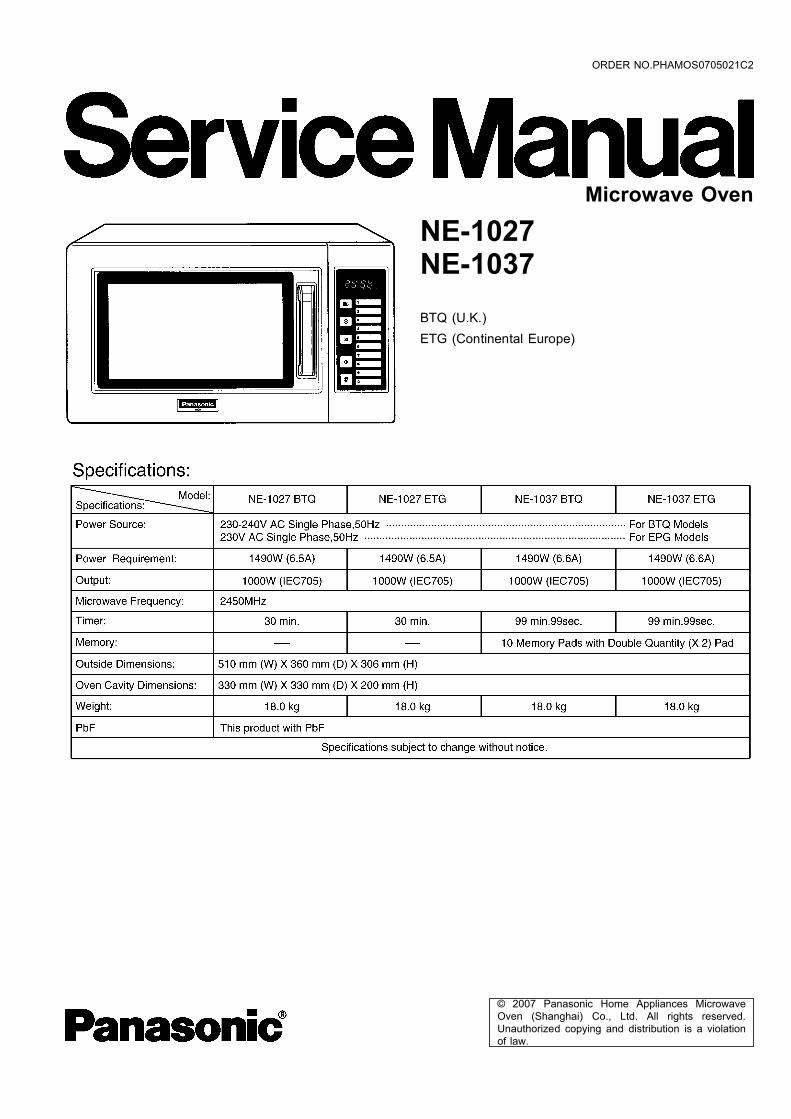
NE-1027NE-1037BTQ (U.K.)ETG (Continental Europe)
Microwave Oven
ORDER NO.PHAMOS0705021C2
2
NE-1027 / NE-1037
1 CONTROL PANEL 4 1.1. NE-1027 4
1.2. NE-1037 5
2 OPERATION PROCEDURE 6 2.1. Manual Heating for Single Stage 6
2.2. Manual Heating for 2nd Stage 6
2.3. Memory Setting for Single Stage Operation Oven is not in
program lock mode. 6
2.4. Memory setting for 2nd stage 7
2.5. Memory Pad Heating 7
2.6. To Read Cycle Counter 8
2.7. To Select Beep Tone Options (ON/OFF of Beep Tone) 8
2.8. To Lock Program of Memory Pad 8
2.9. To Release the Memory Pad Program Lock 8
3 SCHEMATIC DIAGRAM 9 3.1. NE-1027 9
3.2. NE-1037 10
4 DESCRIPTION OF OPERATING SEQUENCE 11 4.1. Variable power cooking control (NE-1027) 11
4.2. Variable power cooking control (NE-1037) 11
5 CAUTIONS TO BE OBSERVED WHEN TROUBLESHOOTING 12 5.1. Check the earthing 12
5.2. If the door lock, the door switch, the door seal or the door
develops a malfunction, be sure not to operate the oven
until complete repairs are made. 12
5.3. Warning about the electric charge in the high voltage
capacitor 12
5.4. When parts must be replaced, remove the power plug
from the outlet. 13
5.5. When the 10 Amp/2.5 Amp fuse is blown due to the
operation of short switch: 13
5.6. Avoid inserting nails, wire, etc. through any holes in the
unit during operation. 13
5.7. Confirm after repair 13
6 DISASSEMBLY AND PARTS REPLACEMENT PROCEDURE 14 6.1. Magnetron 14
6.2. Digital Programmer Circuit (D.P.C.) and membrane
keyboard. (NE-1037) 14
6.3. Low voltage transformer and/or power relays (RY1, RY2,
RY3, RY4) (NE-1037) 15
6.4. Fan motor 15
6.5. Stirrer motor 15
6.6. Door assembly 16
6.7. Temp sensor (thermal protector) (NE-1037) 16
6.8. Floor shelf and/or moving antenna 16
7 COMPONENT TEST PROCEDURE 17 7.1. Primary Latch Switch, (Door Switch and Power Relay B)
Interlocks. 17
7.2. Short Switch & Monitor 17
7.3. High voltage transformer 17
7.4. High voltage capacitor 17
7.5. Magnetron 17
7.6. Variable power controller (NE-1027) 18
7.7. Diode 18
7.8. Protector diode 18
7.9. Membrane key board (Membrane switch assembly)(NE-
1037) 18
7.10. Temp sensor (Thermal protector) (NE-1037) 18
8 MEASUREMENTS AND ADJUSTMENTS 19 8.1. Adjustment of Safety switch A, Safety switch B and short
switch 19
8.2. Measurement of microwave output 19
9 TROUBLESHOOTING GUIDE 20 9.1. NE-1027 20
9.2. NE-1037 22
10 EXPLODED VIEW AND PARTS LIST 26 10.1. EXPLODED VIEW 26
10.2. PARTS LIST 27
10.3. DOOR ASSEMBLY 28
10.4. ESCUTCHEON BASE ASSEMBLY 29
10.5. PACKING AND ACCESSORIES 31
10.6. WIRING MATERIALS 32
11 DIGITAL PROGRAMMER CIRCUIT (NE-1037) 33 11.1. SCHEMATIC DIAGRAM 33
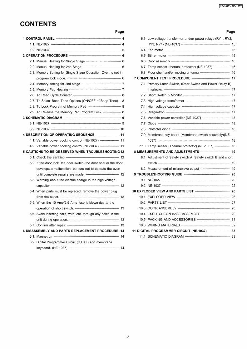
CONTENTS Page Page
3
NE-1027 / NE-1037
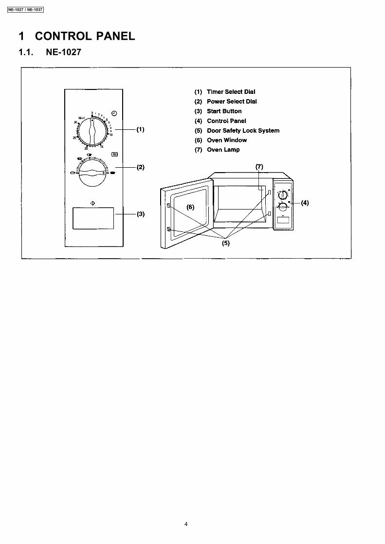
1 CONTROL PANEL1.1. NE-1027
4
NE-1027 / NE-1037
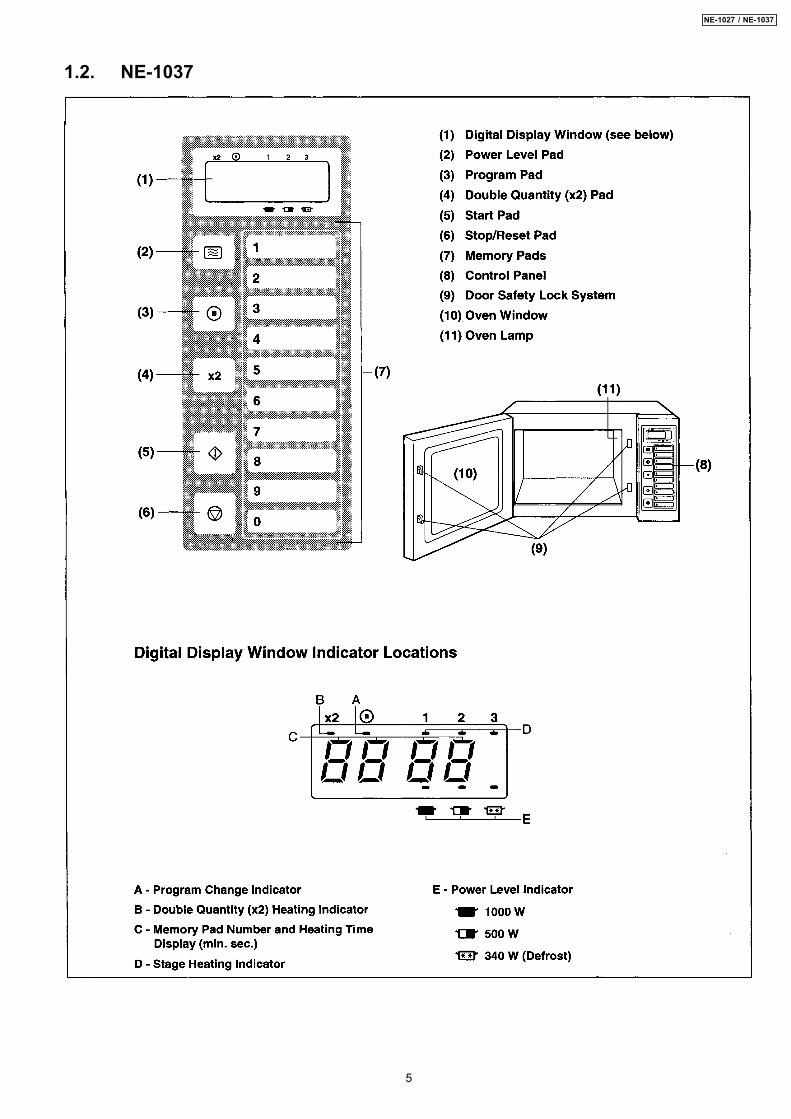
1.2. NE-1037
5
NE-1027 / NE-1037
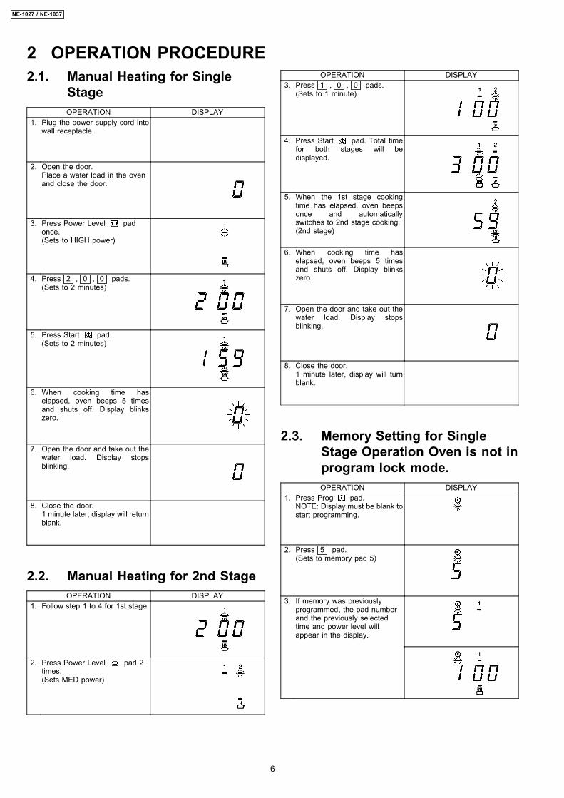
2.1. Manual Heating for SingleStageOPERATION DISPLAY
1. Plug the power supply cord intowall receptacle.
2. Open the door.Place a water load in the ovenand close the door.
3. Press Power Level padonce.(Sets to HIGH power)
4. Press 2 , 0 , 0 pads.(Sets to 2 minutes)
5. Press Start pad.(Sets to 2 minutes)
6. When cooking time haselapsed, oven beeps 5 timesand shuts off. Display blinkszero.
7. Open the door and take out thewater load. Display stopsblinking.
8. Close the door.1 minute later, display will returnblank.
2.2. Manual Heating for 2nd StageOPERATION DISPLAY
1. Follow step 1 to 4 for 1st stage.
2. Press Power Level pad 2times.(Sets MED power)
OPERATION DISPLAY3. Press 1 , 0 , 0 pads.
(Sets to 1 minute)
4. Press Start pad. Total timefor both stages will bedisplayed.
5. When the 1st stage cookingtime has elapsed, oven beepsonce and automaticallyswitches to 2nd stage cooking.(2nd stage)
6. When cooking time haselapsed, oven beeps 5 timesand shuts off. Display blinkszero.
7. Open the door and take out thewater load. Display stopsblinking.
8. Close the door.1 minute later, display will turnblank.
2.3. Memory Setting for SingleStage Operation Oven is not inprogram lock mode.OPERATION DISPLAY
1. Press Prog pad.NOTE: Display must be blank tostart programming.
2. Press 5 pad.(Sets to memory pad 5)
3. If memory was previouslyprogrammed, the pad numberand the previously selectedtime and power level willappear in the display.
2 OPERATION PROCEDURE
6
NE-1027 / NE-1037
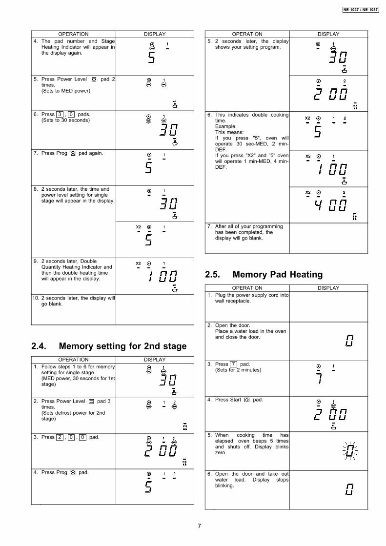
OPERATION DISPLAY4. The pad number and Stage
Heating Indicator will appear inthe display again.
5. Press Power Level pad 2times.(Sets to MED power)
6. Press 3 , 0 pads.(Sets to 30 seconds)
7. Press Prog pad again.
8. 2 seconds later, the time andpower level setting for singlestage will appear in the display.
9. 2 seconds later, DoubleQuantity Heating Indicator andthen the double heating timewill appear in the display.
10. 2 seconds later, the display willgo blank.
2.4. Memory setting for 2nd stageOPERATION DISPLAY
1. Follow steps 1 to 6 for memorysetting for single stage.(MED power, 30 seconds for 1ststage)
2. Press Power Level pad 3times.(Sets defrost power for 2ndstage)
3. Press 2 , 0 , 0 pad.
4. Press Prog pad.
OPERATION DISPLAY5. 2 seconds later, the display
shows your setting program.
6. This indicates double cookingtime.Example:This means:If you press "5", oven willoperate 30 sec-MED, 2 min-DEF.If you press "X2" and "5" ovenwill operate 1 min-MED, 4 min-DEF.
7. After all of your programminghas been completed, thedisplay will go blank.
2.5. Memory Pad HeatingOPERATION DISPLAY
1. Plug the power supply cord intowall receptacle.
2. Open the door.Place a water load in the ovenand close the door.
3. Press 7 pad.(Sets for 2 minutes)
4. Press Start pad.
5. When cooking time haselapsed, oven beeps 5 timesand shuts off. Display blinkszero.
6. Open the door and take outwater load. Display stopsblinking.
7
NE-1027 / NE-1037
OPERATION DISPLAY7. Close the door, display will
return blank after 1 minute.
2.6. To Read Cycle CounterOPERATION DISPLAY
1. Open the door and leave itopen.
2. While pressing Stop/Resetpad, press Power Levelpad. eg. 0010 means the ovenhas been used 1,000 times.9999 means the oven hasbeen used 999,900 times.
3. 2 seconds later, the display willreturn to "0".
2.7. To Select Beep Tone Options(ON/OFF of Beep Tone)OPERATION DISPLAY
1. Open the door.
2. Press Prog pad.
3. Press 0 pad.
4. Press 0 pad again.(No beep tone setting)
5. Press Prog pad again.You have completedprogramming the beep toneoption.
6. 2 seconds later, the display willreturn to "0".
2.8. To Lock Program of MemoryPadOPERATION DISPLAY
1. Plug the power supply cord intowall receptacle.- Display must be blank -
2. Press and hold in the Progpad until the display shows "P"and "L".(Approximately 6 seconds)NOTE: When oven is in"program lock mode", displaywill not show anything andremain blank.
2.9. To Release the Memory PadProgram LockOPERATION DISPLAY
1. Plug the power supply cord intowall receptacle.
2. While pressing and holding theStop/Reset pad, press andhold in the Prog pad untilthe display shows "P".(Approximately 6 seconds)NOTE:When oven is in "programunlock mode", display will notshow anything and remainblank.
8
NE-1027 / NE-1037
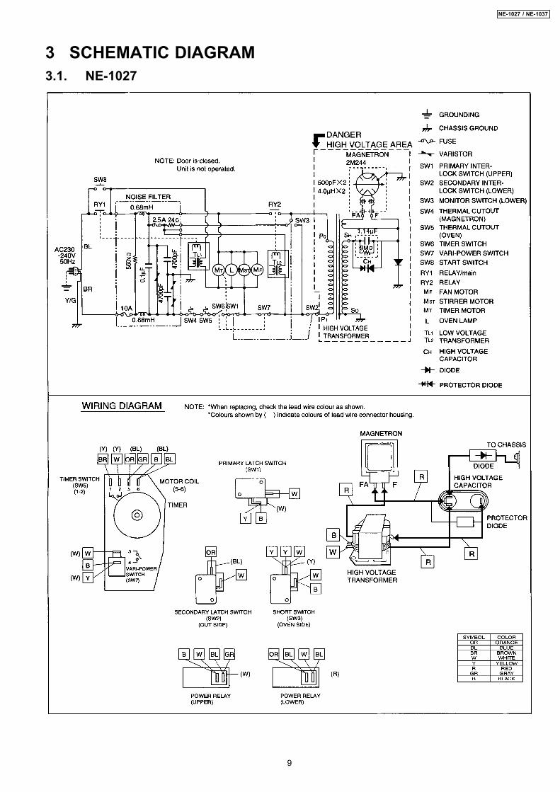
3 SCHEMATIC DIAGRAM3.1. NE-1027
9
NE-1027 / NE-1037
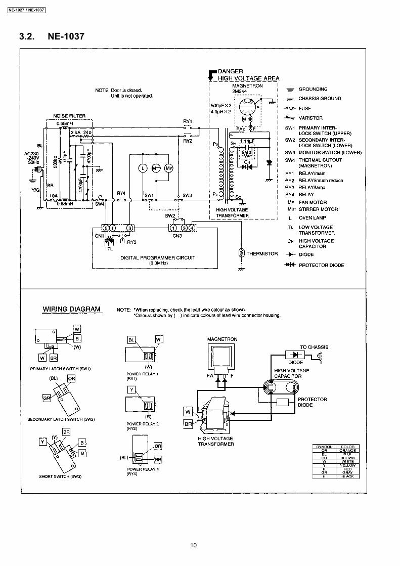
3.2. NE-1037
10
NE-1027 / NE-1037
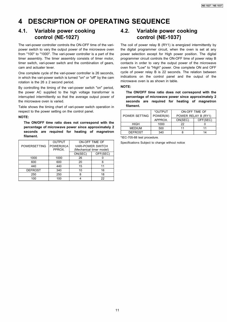
4.1. Variable power cookingcontrol (NE-1027)
The vari-power controller controls the ON-OFF time of the vari-power switch to vary the output power of the microwave ovenfrom "100" to "1000". The vari-power controller is a part of thetimer assembly. The timer assembly consists of timer motor,timer switch, vari-power switch and the combination of gears,cam and actuater lever.One complete cycle of the vari-power controller is 26 seconds,in which the vari-power switch is turned "on" or "off" by the camrotation is the 26 ± 2 second period.By controlling the timing of the vari-power switch "on" period,the power AC supplied to the high voltage transformer isinterrupted intermittently so that the average output power ofthe microwave oven is varied.Table shows the timing chart of vari-power switch operation inrespect to the power setting on the control panel.NOTE:
The ON/OFF time ratio does not correspond with thepercentage of microwave power since approximately 2seconds are required for heating of magnetronfilament.
OUTPUT ON-OFF TIME OFPOWERSETTING POWER(W)A
PPROX.VARI-POWER SWITCH(Mechanical timer model)ON(SEC) OFF(SEC)
1000 1000 26 0600 600 20 6440 440 15 11
DEFROST 340 10 16250 250 8 18100 100 4 22
4.2. Variable power cookingcontrol (NE-1037)
The coil of power relay B (RY1) is energized intermittently bythe digital programmer circuit, when the oven is set at anypower selection except for High power position. The digitalprogrammer circuit controls the ON-OFF time of power relay Bcontacts in order to vary the output power of the microwaveoven from "Low" to "High" power. One complete ON and OFFcycle of power relay B is 22 seconds. The relation betweenindications on the control panel and the output of themicrowave oven is as shown in table.NOTE:
The ON/OFF time ratio does not correspond with thepercentage of microwave power since approximately 2seconds are required for heating of magnetronfilament.
*OUTPUT ON-OFF TIME OFPOWER SETTING POWER(W) POWER RELAY B (RY1)
APPROX. ON(SEC) OFF(SEC)HIGH 1000 22 0
MEDIUM 500 11 11DEFROST 340 8 14
*IEC-705-88 test procedure.
Specifications Subject to change without notice
4 DESCRIPTION OF OPERATING SEQUENCE
11
NE-1027 / NE-1037
Unlike many other appliances, the microwave oven is high-voltage, high-current equipment. Though it is free from dangerin ordinary use, extreme care should be taken during repair.
CAUTIONServicemen should remove their watches whenever working close toor replacing the magnetron.
5.1. Check the earthingDo not operate on a 2 wire extension cord. The microwaveoven is designed to be used in a completely earthed condition.It is imperative, therefore, to make sure it is properly earthedbefore beginning repair work.
5.2. If the door lock, the doorswitch, the door seal or thedoor develops a malfunction,be sure not to operate theoven until complete repairsare made.
If the oven is operated with any of these parts in imperfectcondition, hazardous microwave leakage might occur.
WARNINGNever operate the oven until the following are confirmed:(A) The door is tightly closed.(B) There is no broken hinge or door arm.(C) The door seal is not damaged.(D) The door is not bent or warped.(E) There is no other visible damage.
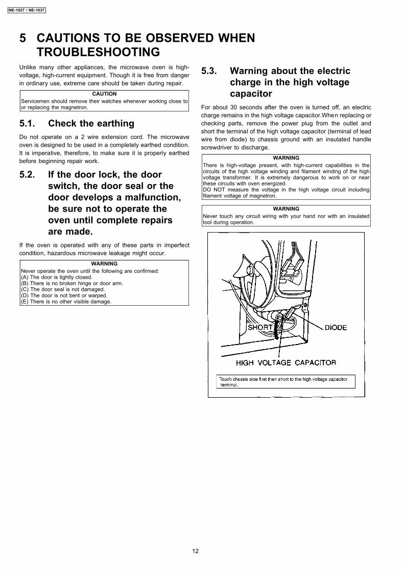
5.3. Warning about the electriccharge in the high voltagecapacitor
For about 30 seconds after the oven is turned off, an electriccharge remains in the high voltage capacitor.When replacing orchecking parts, remove the power plug from the outlet andshort the terminal of the high voltage capacitor (terminal of leadwire from diode) to chassis ground with an insulated handlescrewdriver to discharge.
WARNINGThere is high-voltage present, with high-current capabilities in thecircuits of the high voltage winding and filament winding of the highvoltage transformer. It is extremely dangerous to work on or nearthese circuits with oven energized.DO NOT measure the voltage in the high voltage circuit includingfilament voltage of magnetron.
WARNINGNever touch any circuit wiring with your hand nor with an insulatedtool during operation.
5 CAUTIONS TO BE OBSERVED WHENTROUBLESHOOTING
12
NE-1027 / NE-1037
5.4. When parts must be replaced,remove the power plug fromthe outlet.
5.5. When the 10 Amp/2.5 Ampfuse is blown due to theoperation of short switch:
WARNINGWhen the 10 Amp/2.5 Amp fuse is blown due to operation of theinterlock monitor switch, you must replace all of the components(Primary latch switch, Door switch, Short switch and Power relay B(RY1)).
1. This is mandatory. Refer to “Adjustments andMeasurement” for these switches.
2. When replacing the fuse, confirm that it has the appropriaterating for these models.
3. When replacing faulty switches, be sure mounting tabs arenot bent, broken or otherwise deficient in their ability to holdthe switches.
5.6. Avoid inserting nails, wire, etc.through any holes in the unitduring operation.
Never insert a wire, nail or any other metal object through thelamp holes on the cavity or any other holes or gaps, becausesuch objects may work as an antenna and cause microwaveleakage.
5.7. Confirm after repair 1. After repair or replacement of parts, make sure that the
screws of the oven, etc. are neither loose nor missing.Microwaves might leak if screws are not properly tightened.
2. Make sure that all electrical connections are tight beforeinserting the plug into the wall outlet.
3. Check for microwave energy leakage. (Refer to procedurefor measuring microwave evergy leakage.)
CAUTIONMICROWAVE RADIATION
USE CAUTION NOT TO BECOME EXPOSED TO RADIATIONFROM THE MICROWAVE MAGNETRON OR OTHER PARTSCONDUCTING MICROWAVE ENERGY.
IMPORTANT NOTICE1.The following components have potentials above 2000V while theappliance is operated.* Magnetron* High voltage transformer* High voltage diode* High voltage capacitorPay special attention to these areas.2.When the appliance is operated with the door hinge or magnetronadjusted incorrectly, the microwave leakage can exceed more than5mW/cm2. After repair or exchange, it is very important to check thatmagnetron and the door hinge is correctly installed.
13
NE-1027 / NE-1037
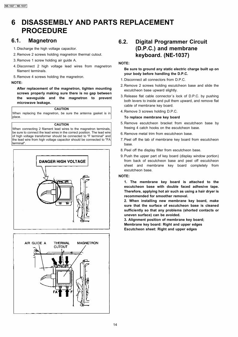
6.1. Magnetron 1. Discharge the high voltage capacitor. 2. Remove 2 screws holding magnetron thermal cutout. 3. Remove 1 screw holding air guide A. 4. Disconnect 2 high voltage lead wires from magnetron
filament terminals. 5. Remove 4 screws holding the magnetron.NOTE:
After replacement of the magnetron, tighten mountingscrews properly making sure there is no gap betweenthe waveguide and the magnetron to preventmicrowave leakage.
CAUTIONWhen replacing the magnetron, be sure the antenna gasket is inplace.
CAUTIONWhen connecting 2 filament lead wires to the magnetron terminals,be sure to connect the lead wires in the correct position. The lead wireof high voltage transformer should be connected to "F terminal" andthe lead wire from high voltage capacitor should be connected to "FAterminal".
6.2. Digital Programmer Circuit(D.P.C.) and membranekeyboard. (NE-1037)
NOTE:Be sure to ground any static electric charge built up onyour body before handling the D.P.C.
1. Disconnect all connectors from D.P.C. 2. Remove 2 screws holding escutcheon base and slide the
escutcheon base upward slightly. 3. Release flat cable connector´s lock of D.P.C. by pushing
both levers to inside and pull them upward, and remove flatcable of membrane key board.
4. Remove 3 screws holding D.P.C.To replace membrane key board
5. Remove escutcheon bracket from escutcheon base byfreeing 4 catch hooks on the escutcheon base.
6. Remove metal trim from escutcheon base. 7. Peel off the tab of membrane key board from escutcheon
base. 8. Peel off the display filter from escutcheon base. 9. Push the upper part of key board (display window portion)
from back of escutcheon base and peel off escutcheonsheet and membrane key board completely fromescutcheon base.
NOTE:1. The membrane key board is attached to theescutcheon base with double faced adhesive tape.Therefore, applying hot air such as using a hair dryer isrecommended for smoother removal.2. When installing new membrane key board, makesure that the surface of escutcheon base is cleanedsufficiently so that any problems (shorted contacts oruneven surface) can be avoided.3. Alignment position of membrane key board;Membrane key board: Right and upper edgesEscutcheon sheet: Right and upper edges
6 DISASSEMBLY AND PARTS REPLACEMENTPROCEDURE
14
NE-1027 / NE-1037
6.3. Low voltage transformerand/or power relays (RY1,RY2, RY3, RY4) (NE-1037)
NOTE:Be sure to ground any static electric charge built up onyour body before handling the D.P.C..
1. Using solder wick or a desoldering tool and 30W solderingiron, carefully remove all solder from the terminal pins of thelow voltage transformer and/or power relays.NOTE:
Do not use a soldering iron or desoldering tool ofmore than 30 watts on D.P.C. contacts.
2. With all the terminal pins cleaned and seperated fromD.P.C. contacts, remove the defective transformer/powerrelays and install new transformer/power relays makingsure all terminal pins are inserted completely. Resolder allterminal contacts carefully.
6.4. Fan motor 1. Disconnect 2 lead wires from fan motor terminals. 2. Disconnect 3 lead wires from noise filter P.C.B. terminals. 3. Disconnect 4 high voltage lead wires from high voltage
capacitor terminals. 4. Remove 5 screws holding fan motor and orifice assy,
detach the orifice assy with fan motor from oven assy. 5. Remove fan blade from the fan motor shaft by pulling it
straight Out. 6. Separate the fan motor from the orifice assy by freeing 2
catch hooks on the orifice assy.
6.5. Stirrer motor 1. Remove the motor cover by breaking off at the 8 spots
indicated by arrows with a cutter or the like. (See Figure)Note:
After breaking off the motor cover, make sure the cut-offportions are properly trimmed off or bend to inside sothat no sharp edge will expose to outside.
2. Disconnect 2 lead wires connected to the stirrer motor. 3. Remove the stirrer motor by removing 2 screws.
Note:To reinstall the motor cover, use 4x6 screw.
15
NE-1027 / NE-1037
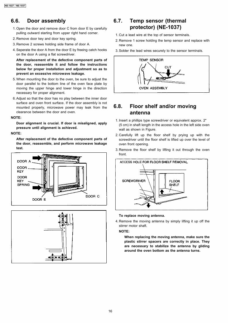
6.6. Door assembly 1. Open the door and remove door C from door E by carefully
pulling outward starting from upper right hand corner. 2. Remove door key and door key spring. 3. Remove 2 screws holding side frame of door A. 4. Seperate the door A from the door E by freeing catch hooks
on the door A using a flat screwdriver.After replacement of the defective component parts ofthe door, reassemble it and follow the instructionsbelow for proper installation and adjustment so as toprevent an excessive microwave leakage.
5. When mounting the door to the oven, be sure to adjust thedoor parallel to the bottom line of the oven face plate bymoving the upper hinge and lower hinge in the directionnecessary for proper alignment.
6. Adjust so that the door has no play between the inner doorsurface and oven front surface. If the door assembly is notmounted properly, microwave power may leak from theclearance between the door and oven.
NOTE:Door alignment is crucial. If door is misaligned, applypressure until alignment is achieved.
NOTE:After replacement of the defective component parts ofthe door, reassemble, and perform microwave leakagetest.
6.7. Temp sensor (thermalprotector) (NE-1037)
1. Cut a lead wire at the top of sensor terminals. 2. Remove 1 screw holding the temp sensor and replace with
new one. 3. Solder the lead wires securely to the sensor terminals.
6.8. Floor shelf and/or movingantenna
1. Insert a phillips type screwdriver or equivalent approx. 2"(5 cm) in shaft length in the access hole in the left side ovenwall as shown in Figure.
2. Carefully lift up the floor shelf by prying up with thescrewdriver until the floor shelf is lifted up over the level ofoven front opening.
3. Remove the floor shelf by lifting it out through the ovenfront.
To replace moving antenna. 4. Remove the moving antenna by simply lifting it up off the
stirrer motor shaft.NOTE:
When replacing the moving antenna, make sure theplastic stirrer spacers are correctly in place. Theyare necessary to stabilize the antenna by glidingaround the oven bottom as the antenna turns.
16
NE-1027 / NE-1037
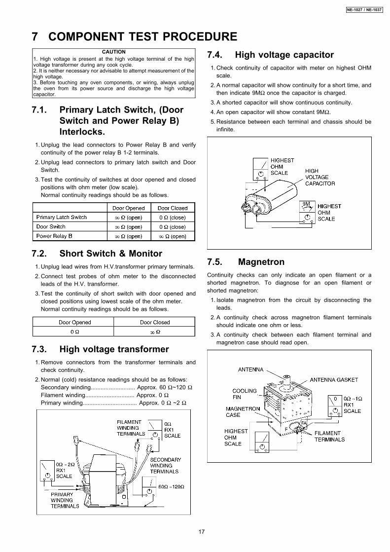
CAUTION1. High voltage is present at the high voltage terminal of the highvoltage transformer during any cook cycle.2. It is neither necessary nor advisable to attempt measurement of thehigh voltage.3. Before touching any oven components, or wiring, always unplugthe oven from its power source and discharge the high voltagecapacitor.
7.1. Primary Latch Switch, (DoorSwitch and Power Relay B)Interlocks.
1. Unplug the lead connectors to Power Relay B and verifycontinuity of the power relay B 1-2 terminals.
2. Unplug lead connectors to primary latch switch and DoorSwitch.
3. Test the continuity of switches at door opened and closedpositions with ohm meter (low scale).Normal continuity readings should be as follows.
7.2. Short Switch & Monitor 1. Unplug lead wires from H.V.transformer primary terminals. 2. Connect test probes of ohm meter to the disconnected
leads of the H.V. transformer. 3. Test the continuity of short switch with door opened and
closed positions using lowest scale of the ohm meter.Normal continuity readings should be as follows.
7.3. High voltage transformer 1. Remove connectors from the transformer terminals and
check continuity. 2. Normal (cold) resistance readings should be as follows:
Secondary winding........................... Approx. 60 Ω~120 ΩFilament winding.............................. Approx. 0 ΩPrimary winding................................. Approx. 0 Ω ~2 Ω
7.4. High voltage capacitor 1. Check continuity of capacitor with meter on highest OHM
scale. 2. A normal capacitor will show continuity for a short time, and
then indicate 9MΩ once the capacitor is charged. 3. A shorted capacitor will show continuous continuity. 4. An open capacitor will show constant 9MΩ. 5. Resistance between each terminal and chassis should be
infinite.
7.5. MagnetronContinuity checks can only indicate an open filament or ashorted magnetron. To diagnose for an open filament orshorted magnetron: 1. Isolate magnetron from the circuit by disconnecting the
leads. 2. A continuity check across magnetron filament terminals
should indicate one ohm or less. 3. A continuity check between each filament terminal and
magnetron case should read open.
7 COMPONENT TEST PROCEDURE
17
NE-1027 / NE-1037
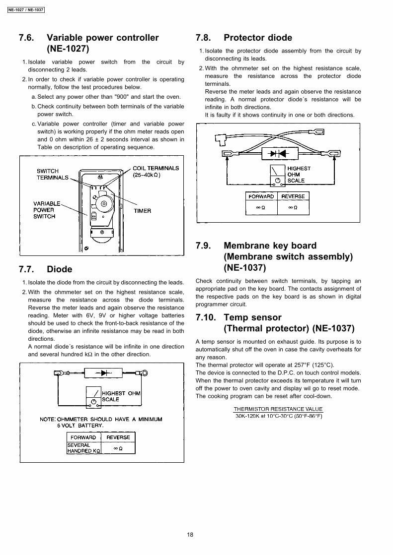
7.6. Variable power controller(NE-1027)
1. Isolate variable power switch from the circuit bydisconnecting 2 leads.
2. In order to check if variable power controller is operatingnormally, follow the test procedures below. a. Select any power other than "900" and start the oven. b. Check continuity between both terminals of the variable
power switch. c. Variable power controller (timer and variable power
switch) is working properly if the ohm meter reads openand 0 ohm within 26 ± 2 seconds interval as shown inTable on description of operating sequence.
7.7. Diode 1. Isolate the diode from the circuit by disconnecting the leads. 2. With the ohmmeter set on the highest resistance scale,
measure the resistance across the diode terminals.Reverse the meter leads and again observe the resistancereading. Meter with 6V, 9V or higher voltage batteriesshould be used to check the front-to-back resistance of thediode, otherwise an infinite resistance may be read in bothdirections.A normal diode´s resistance will be infinite in one directionand several hundred kΩ in the other direction.
7.8. Protector diode 1. Isolate the protector diode assembly from the circuit by
disconnecting its leads. 2. With the ohmmeter set on the highest resistance scale,
measure the resistance across the protector diodeterminals.Reverse the meter leads and again observe the resistancereading. A normal protector diode´s resistance will beinfinite in both directions.It is faulty if it shows continuity in one or both directions.
7.9. Membrane key board(Membrane switch assembly)(NE-1037)
Check continuity between switch terminals, by tapping anappropriate pad on the key board. The contacts assignment ofthe respective pads on the key board is as shown in digitalprogrammer circuit.
7.10. Temp sensor(Thermal protector) (NE-1037)
A temp sensor is mounted on exhaust guide. Its purpose is toautomatically shut off the oven in case the cavity overheats forany reason.The thermal protector will operate at 257°F (125°C).The device is connected to the D.P.C. on touch control models.When the thermal protector exceeds its temperature it will turnoff the power to oven cavity and display wil go to reset mode.The cooking program can be reset after cool-down.
18
NE-1027 / NE-1037
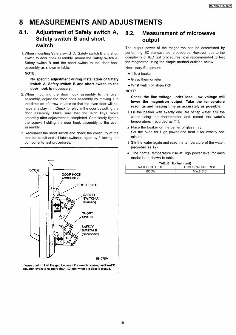
8.1. Adjustment of Safety switch A,Safety switch B and shortswitch
1. When mounting Safety switch A, Safety switch B and shortswitch to door hook assembly, mount the Safety switch A,Safety switch B and the short switch to the door hookassembly as shown in table.NOTE:
No specific adjustment during installation of Safetyswitch A, Safety switch B and short switch to thedoor hook is necessary.
2. When mounting the door hook assembly to the ovenassembly, adjust the door hook assembly by moving it inthe direction of arrow in table so that the oven door will nothave any play in it. Check for play in the door by pulling thedoor assembly. Make sure that the latch keys movesmoothly after adjustment is completed. Completely tightenthe screws holding the door hook assembly to the ovenassembly.
3. Reconnect the short switch and check the continuity of themonitor circuit and all latch switches again by following thecomponents test procedures.
8.2. Measurement of microwaveoutput
The output power of the magnetron can be determined byperforming IEC standard test procedures. However, due to thecomplexity of IEC test procedures, it is recommended to testthe magnetron using the simple method outlined below.Necessary Equipment:
••••
1 litre beaker
••••
Glass thermometer
••••
Wrist watch or stopwatchNOTE:
Check the line voltage under load. Low voltage willlower the magnetron output. Take the temperaturereadings and heating time as accurately as possible.
1. Fill the beaker with exactly one litre of tap water. Stir thewater using the thermometer and record the water’stemperature. (recorded as T1).
2. Place the beaker on the center of glass tray.Set the oven for High power and heat it for exactly oneminute.
3. Stir the water again and read the temperature of the water.(recorded as T2).
4. The normal temperature rise at High power level for eachmodel is as shown in table.
TABLE (1L-1min.test)RATED OUTPUT TEMPERATURE RISE
1000W Min.8.5°C
8 MEASUREMENTS AND ADJUSTMENTS
19
NE-1027 / NE-1037
9 TROUBLESHOOTING GUIDE9.1. NE-1027
CAUTION1. Check grounding before checking for trouble.2. Be cafeful of the high voltage circuit.3. Discharge high voltage capacitor.4. When checking the continuity of the switches or the high voltage transformer, disconnect one lead wire from these parts and then check
continuity with the AC plug removed. To do otherwise may result in a false reading or damage to your meter.When disconnecting a plastic connector from a terminal, you must hold the plastic connector instead of the lead wire and then disconnect it,otherwise lead wire may be damaged or the connector cannot by removed.
First of all operate the microwave oven following the correct operating procedures in order to find the exact cause of any trouble.
9.1.1. [TROUBLE 1] Oven does not start cookingSYMPTOM CAUSE CORRECTIONS
1. Oven is dead. 1. Open or loose lead wire harnessFuses is OK. 2. Open thermal cutout (Magnetron)(Oven) Check fan motor when thermal cutout is defective.
2. No microwave oscillation. 1. Off-alignment of latch switches Adjust door and latch switches.Other operation is OK. 2. Defective secondary latch switch (SW2)
3. Open or loose wiring of secondary latch switch,vari-power switch and micro select switch
4. Defective variable power switch (SW7) Refer to component test procedure.5. Open or loose connection of high voltage
circuit especially magnetron filament circuitNOTE: Large contact resistance will bring lowermagnetron filament voltage and causingmagnetron to lower output and/or intermittentoscillation.
6. Defective high voltage componentH.V. TransformerH.V. CapacitorH.V. DiodeMagnetron
Check high voltage component according tocomponent test procedure and replace if it is defective.
20
NE-1027 / NE-1037

9.1.2. [TROUBLE 2] Fuse is blownSYMPTOM CAUSE CORRECTIONS
1. 10A fuse is blown. 1. Shorted lead wire harness2. Shorted H.V. Capacitor3. Shorted H.V. Diode Replace H.V. Diode and protector diode
(*NOTE)4. Defective magnetron Replace magnetron and protector diode
(*NOTE)5. Shorted H.V. Transformer Replace H.V.Transformer and protector diode
(*NOTE)6. Shorted Protector diode
2. 2.5A fuse is blown. 1. Defctive primary latch switch and short switch Check adjustment of primary, secondary latchswitch and short switch including door.
2. Open or loose wiring of power relay (RY2)3. Defective power relay (RY2)4. Defective relay control circuit
*NOTE:Be sure to replace protector diode together with those H.V.components.In this case, only D2 of protector diode may be shorted due to faulty H.V.component. Therefore,if protector diode is not replaced together, high voltage transformer will be damaged (overheated).
9.1.3. [TROUBLE 3] Other troublesSYMPTOM CAUSE CORRECTIONS
1. Microwave output is low. 1. Decrease in power source voltage Consult electricianOven takes longer time to cook food. 2. Open or loose wiring of magnetron filament
circuit. (Intermittent oscillation)3. Aging change of magnetron
2. Loud buzzing noise can be heard. 1. Loose fan and fan motor2. Loose screws on H.V. Transformer
21
NE-1027 / NE-1037
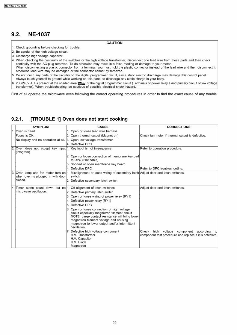
9.2. NE-1037CAUTION
1. Check grounding before checking for trouble.2. Be careful of the high voltage circuit.3. Discharge high voltage capacitor.4. When checking the continuity of the switches or the high voltage transformer, disconnect one lead wire from these parts and then check
continuity with the AC plug removed. To do otherwise may result in a false reading or damage to your meter.When disconnecting a plastic connector from a terminal, you must hold the plastic connector instead of the lead wire and then disconnect it,otherwise lead wire may be damaged or the connector cannot by removed.
5. Do not touch any parts of the circuitry on the digital programmer circuit, since static electric discharge may damage this control panel.Always touch yourself to ground while working on this panel to discharge any static charge in your body.
6. 230/240V AC is present at the shaded area of the digital programmer circuit (Terminals of power relay´s and primary circuit of low voltagetransformer). When troubleshooting, be cautious of possible electrical shock hazard.
First of all operate the microwave oven following the correct operating procedures in order to find the exact cause of any trouble.
9.2.1. [TROUBLE 1] Oven does not start cookingSYMPTOM CAUSE CORRECTIONS
1. Oven is dead. 1. Open or loose lead wire harnessFuses is OK. 2. Open thermal cutout (Magnetron) Check fan motor if thermal cutout is defective.No display and no operation at all. 3. Open low voltage transformer
4. Defective DPC2. Oven does not accept key input
(Program)1. Key input is not in-sequence Refer to operation procedure.
2. Open or loose connection of membrane key padto DPC (Flat cable)
3. Shorted or open membrane key board4. Defective DPC Refer to DPC troubleshooting.
3. Oven lamp and fan motor turn onwhen oven is plugged in with doorclosed.
1. Misalignment or loose wiring of secondary latchswitch
Adjust door and latch switches.
2. Defective secondary latch switch
4. Timer starts count down but nomicrowave oscillation.
1. Off-alignment of latch switches Adjust door and latch switches.2. Defective primary latch switch3. Open or loose wiring of power relay (RY1)4. Defective power relay (RY1)5. Defective DPC.6. Open or loose connection of high voltage
circuit especially magnetron filament circuitNOTE: Large contact resistance will bring lowermagnetron filament voltage and causingmagnetron to lower output and/or intermittentoscillation.
7. Defective high voltage componentH.V. TransformerH.V. CapacitorH.V. DiodeMagnetron
Check high voltage component according tocomponent test procedure and replace if it is defective.
22
NE-1027 / NE-1037
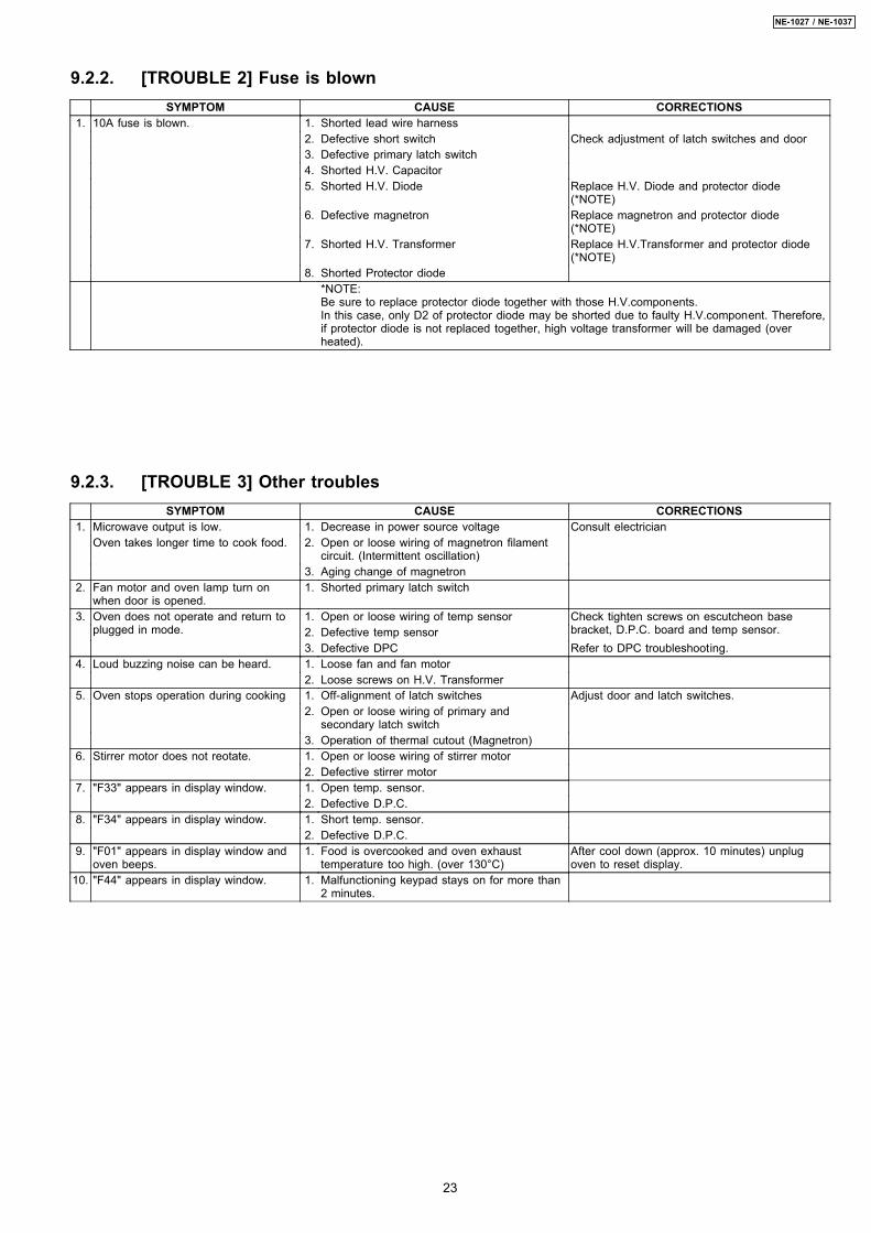
9.2.2. [TROUBLE 2] Fuse is blownSYMPTOM CAUSE CORRECTIONS
1. 10A fuse is blown. 1. Shorted lead wire harness2. Defective short switch Check adjustment of latch switches and door3. Defective primary latch switch4. Shorted H.V. Capacitor5. Shorted H.V. Diode Replace H.V. Diode and protector diode
(*NOTE)6. Defective magnetron Replace magnetron and protector diode
(*NOTE)7. Shorted H.V. Transformer Replace H.V.Transformer and protector diode
(*NOTE)8. Shorted Protector diode
*NOTE:Be sure to replace protector diode together with those H.V.components.In this case, only D2 of protector diode may be shorted due to faulty H.V.component. Therefore,if protector diode is not replaced together, high voltage transformer will be damaged (overheated).
9.2.3. [TROUBLE 3] Other troublesSYMPTOM CAUSE CORRECTIONS
1. Microwave output is low. 1. Decrease in power source voltage Consult electricianOven takes longer time to cook food. 2. Open or loose wiring of magnetron filament
circuit. (Intermittent oscillation)3. Aging change of magnetron
2. Fan motor and oven lamp turn onwhen door is opened.
1. Shorted primary latch switch
3. Oven does not operate and return toplugged in mode.
1. Open or loose wiring of temp sensor Check tighten screws on escutcheon basebracket, D.P.C. board and temp sensor.2. Defective temp sensor
3. Defective DPC Refer to DPC troubleshooting.4. Loud buzzing noise can be heard. 1. Loose fan and fan motor
2. Loose screws on H.V. Transformer5. Oven stops operation during cooking 1. Off-alignment of latch switches Adjust door and latch switches.
2. Open or loose wiring of primary andsecondary latch switch
3. Operation of thermal cutout (Magnetron)6. Stirrer motor does not reotate. 1. Open or loose wiring of stirrer motor
2. Defective stirrer motor7. "F33" appears in display window. 1. Open temp. sensor.
2. Defective D.P.C.8. "F34" appears in display window. 1. Short temp. sensor.
2. Defective D.P.C.9. "F01" appears in display window and
oven beeps.1. Food is overcooked and oven exhaust
temperature too high. (over 130°C)After cool down (approx. 10 minutes) unplugoven to reset display.
10. "F44" appears in display window. 1. Malfunctioning keypad stays on for more than2 minutes.
23
NE-1027 / NE-1037
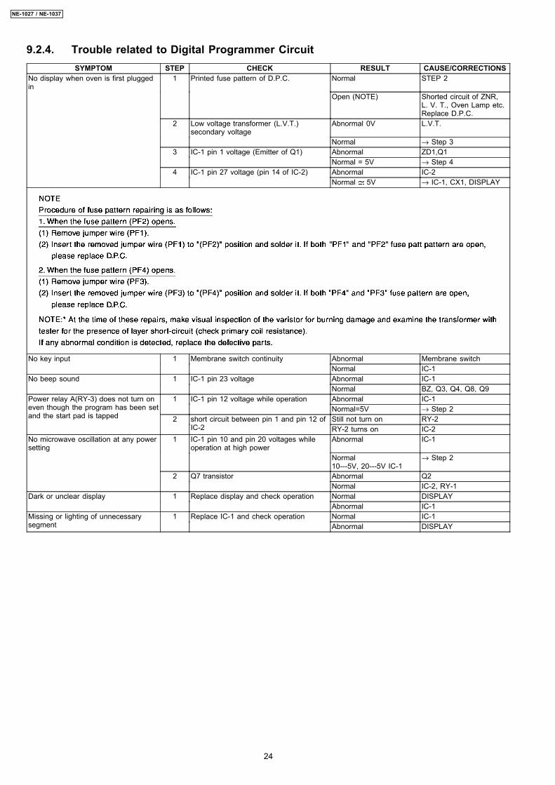
9.2.4. Trouble related to Digital Programmer CircuitSYMPTOM STEP CHECK RESULT CAUSE/CORRECTIONS
No display when oven is first pluggedin
1 Printed fuse pattern of D.P.C. Normal STEP 2
Open (NOTE) Shorted circuit of ZNR,L. V. T., Oven Lamp etc.Replace D.P.C.
2 Low voltage transformer (L.V.T.)secondary voltage
Abnormal 0V L.V.T.
Normal → Step 33 IC-1 pin 1 voltage (Emitter of Q1) Abnormal ZD1,Q1
Normal = 5V → Step 44 IC-1 pin 27 voltage (pin 14 of IC-2) Abnormal IC-2
Normal 5V → IC-1, CX1, DISPLAY
No key input 1 Membrane switch continuity Abnormal Membrane switchNormal IC-1
No beep sound 1 IC-1 pin 23 voltage Abnormal IC-1Normal BZ, Q3, Q4, Q8, Q9
Power relay A(RY-3) does not turn oneven though the program has been setand the start pad is tapped
1 IC-1 pin 12 voltage while operation Abnormal IC-1Normal=5V → Step 2
2 short circuit between pin 1 and pin 12 ofIC-2
Still not turn on RY-2RY-2 turns on IC-2
No microwave oscillation at any powersetting
1 IC-1 pin 10 and pin 20 voltages whileoperation at high power
Abnormal IC-1
Normal10---5V, 20---5V IC-1
→ Step 2
2 Q7 transistor Abnormal Q2Normal IC-2, RY-1
Dark or unclear display 1 Replace display and check operation Normal DISPLAYAbnormal IC-1
Missing or lighting of unnecessarysegment
1 Replace IC-1 and check operation Normal IC-1Abnormal DISPLAY
24
NE-1027 / NE-1037
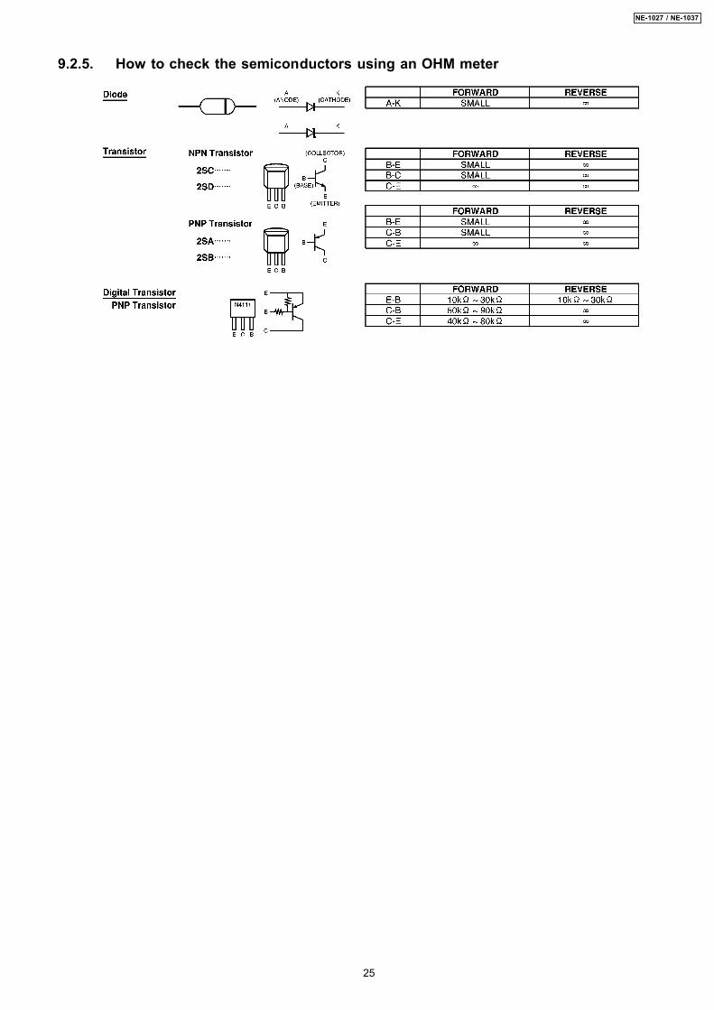
9.2.5. How to check the semiconductors using an OHM meter
25
NE-1027 / NE-1037


![DIPLOMA IN MARINE ENGINEERING [1027]](https://img.pdfslide.us/doc/110x75/6231bf6cb0de79100a114993/diploma-in-marine-engineering-1027.jpg)