Embed Size (px)
Citation preview
1 MICROWAVE AND RADAR LAB (EE-322-F)
MICROWAVE AND RADAR LAB
(EE-322-F)
LAB MANUAL
VI SEMESTER
RAO PAHALD SINGH GROUP OF INSTITUTIONS
BALANA(MOHINDERGARH)123029
Department Of Electronics and Communication Engg.
RPS CET ,Balana(M/Garh)
2 MICROWAVE AND RADAR LAB (EE-322-F)
LIST OF EXPERIMENTS
SR.
NO. NAME OF EXPERIMENT
PAGENO.
1 To study wave guide components. 3-4
2 To study the characteristics of Gunn oscillator Gun diode as modulated
source.
5-6
3 Study of wave guide horn and its radiation pattern and determination of
the beam width.
7-8
4 To study isolation and coupling coefficient of a magic Tee. 9-10
5 To measure coupling coefficient, Insertion loss & Directivity of a
Directional coupler.
11-13
6 To measure attenuation and insertion loss of a fixed and variable
attenuator.
14-15
7 To measure isolation and insertion loss of a three port
Circulators/Isolator.
16-17
8 To measure the standing wave ratio and reflection coefficient in a
Microwave Transmission line.
18-19
9 To measure the frequency of a microwave source and demonstrate
relationship among guide dimensions, free space wavelength and guide
wavelength.
20-21
10 To measure the impedance of unknown load.
22-24
3 MICROWAVE AND RADAR LAB (EE-322-F)
EXPERIMENT 1
AIM: To study wave guide components.
THEORETICAL CONCEPT: A pipe with any sort of cross- section that could be used as a
wave guide or system of conductors for carrying electromagnetic wave is called a wave guide in
which the waves are truly guided.
(1) FLANGES: - Flanges are used to couple sections of wave guide components. These flanges
are designed to have not only mechanical strength but also desirable electric characteristics.
(2)TWISTED WAVEGUIDE: - If a change in polarization direction is required, twisted section
may be used. It is also called rotator.
(3)WAVE GUIDE TEE: - Tees are junctions which are required to combine or split two signals
in a wave guide. Different type of tees are :-
(a) H - PLANE TEE: - All the arm of the H- plane Tee lies in the plane of the magnetic field
which divides among the arm. This is thus a current or parallel junction.
(b) E- PLANE TEE: - It lies in the plane of electric field. It is voltage or series junction. In this
signal is divided in to two parts having same magnitude but in opposite phase.
(c) MAGIC TEE: - If another arm is added to either of the T-junction. Then a hybrid T-junction
or magic tee is obtained. The arm three or four is connected to arm 1&2 but not to each other.
(4) DIRECTION COUPLER: - The power delivered to a load or an antenna can be measured
using sampling technique in which a known fraction of the power is measured so that the total
may be calculated. A number of coupling units used for such purpose are known as directional
coupler.
(5) ATTENUATORS: - It consists of a resistive wane inside the wave guide to absorb
microwave power according to its position w.r.t side wall of the wave guide. Attenuation will be
maximum if the wane is placed at center.
(a) Fixed Attenuators: In this the position of resistive wane is fixed, it absorbs constant amount
of power.
(b) Variable Attenuators: - In this the position of resistive wane can be changed with the help
of micrometer.
(6) ISOLATORS: - Ferrite is used as the main material in isolator. Isolator is a microwave
device which allows RF energy to pass through in one direction with very little loss, while RF
power in the reverse direction is absorbed.
(7) CIRCULATORS: - A microwave circulator is a multi port junction device where the power
may flow in the direction from 1 to 2, 2 to 3, & so on...
(8) MATCHED TERMINATION: - A termination producing no reflected wave at any
transverse section of the wave guide. It absorbs all the incident wave. This is also equivalent to
connecting the line with its characteristic impedance.
(9) SLOTTED SECTION: - A length of wave guide in which a non radiating slot is cut on the
broader side. This is used to measure the VSWR.
(10) SLIDE SCREW TUNER: - A screw or probe inserted at the top of wave guide (parallel to
E) to develop susceptance the magnitude & sign of which is controlled by depth of penetration of
screw and it can be moved along the length of wave guide.
4 MICROWAVE AND RADAR LAB (EE-322-F)
(11) H – PLANE BEND: - An H-plane bend is a piece of wave guide smoothly bends in a plane
parallel to magnetic field for the dominant mode (Hard bend).
(12) E – PLANE BEND: - An E-plane bend is a piece of wave guide smoothly bends in a plane
of electric field (Easy bend).
(13) HORN ANTENNAS: - The component which radiates & intercepts EM energy is of course
the antenna. The open-ended wave guide, in which the open end is flared so that it looks like a
horn, is called horn antenna. There are several types of horns – Sectional E-plane horn, Sectional
H- plane horn and Pyramidal horn.
(14) MOVABLE SHORT: - It is adjustable load which moves along the length of wave guide
and adjusted to get SWR.
SPECIFICATION OF APPARATUS USED: Flanges, Twisted wave guide, wave guide tees,
Directional Coupler, Attenuator, Isolators, Circulators, Matched terminator, Slide screw tuner,
Slotted Section, Tunable probe, Horn antennas, Movable Short, Detector mount.
PRECAUTIONS:
1. Handle all components with care and do not allow any damage to take place.
2. Do not rub/scratch the inner polished surfaces of the components with any sharp edged body.
3. If demonstrating any assembly of components, ensure that there is no cross threading and
proper tightening.
RESULT & COMENTS: Students have been able to appreciate the purpose and usage of
various Components.
APPLICATION:
1. Waveguide components can be used in microwave communication system.
2. Used in different antenna system for communication purpose.
5 MICROWAVE AND RADAR LAB (EE-322-F)
EXPERIMENT 2
AIM: To study the characteristics of gunn oscillator, gunn diode as modulated source.
THEORETICAL CONCEPT: The gunn oscillator is based on negative differential
conductivity effect in bulk semiconductor which has two conduction bands, minima separated by
an energy gap. A disturbance at the cathode gives rise to high field region which travel towards
the anode. When this high field domain reaches the anode, it disappears and another domain is
formed at the cathode and starts moving towards anode and so on. The time required for domain
to travel from cathode to anode gives oscillation frequency. In a Gunn Oscillator, the Gunn diode
is placed in a resonant cavity, the Oscillation frequency is determined by cavity dimension than
by diode itself.
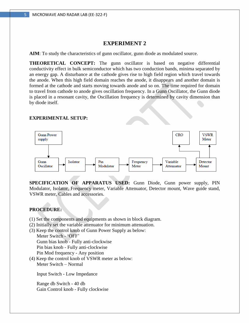
EXPERIMENTAL SETUP:
SPECIFICATION OF APPARATUS USED: Gunn Diode, Gunn power supply, PIN
Modulator, Isolator, Frequency meter, Variable Attenuator, Detector mount, Wave guide stand,
VSWR meter, Cables and accessories.
PROCEDURE:
(1) Set the components and equipments as shown in block diagram.
(2) Initially set the variable attenuator for minimum attenuation.
(3) Keep the control knob of Gunn Power Supply as below:
Meter Switch - ‘OFF’
Gunn bias knob - Fully anti-clockwise
Pin bias knob - Fully anti-clockwise
Pin Mod frequency - Any position
(4) Keep the control knob of VSWR meter as below:
Meter Switch – Normal
Input Switch - Low Impedance
Range db Switch - 40 db
Gain Control knob - Fully clockwise
6 MICROWAVE AND RADAR LAB (EE-322-F)
(5) Set the micrometer of Gunn oscillator for required frequency of operation.
(6) Switch ‘ON’ the Gunn Power Supply, VSWR meter and Cooling Fan
PRECAUTIONS:
1. Use fan to keep the Klystron temperature low.
2. Ensure tight connections of the apparatus
3. Avoid cross connections of the threads.
4. Use stabilized power supply.
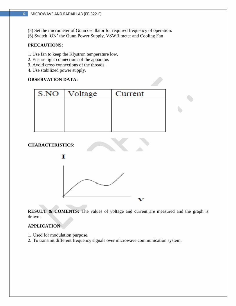
OBSERVATION DATA:
CHARACTERISTICS:
RESULT & COMENTS: The values of voltage and current are measured and the graph is
drawn.
APPLICATION:
1. Used for modulation purpose.
2. To transmit different frequency signals over microwave communication system.
7 MICROWAVE AND RADAR LAB (EE-322-F)
EXPERIMENT 3
AIM: Study of wave guide horn and its radiation pattern and determination of the beam width.
THEORETICAL CONCEPT: If a transmission line propagating energy is left open at one end,
there will be radiation from this end. In case of a rectangular wave guide this antenna presents a
mismatch of about 2:1 and it radiates in many directions. The match will improve if the open
wave guide is a horn shape. The radiation pattern of an antenna is a diagram of field strength or
more often the power intensity as a junction of the aspect angle at constant distance from the
radiating antenna. An antenna pattern consists of several lobes, the main lobe, side lobe, and
back lobe. The major power is concentrated in the main lobe and it is normally to keep the power
in the side lobes and back lobe as low as possible.
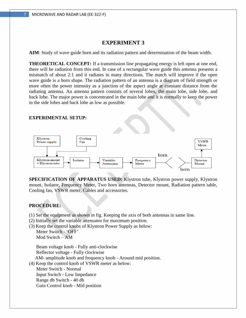
EXPERIMENTAL SETUP:
SPECIFICATION OF APPARATUS USED: Klystron tube, Klystron power supply, Klystron
mount, Isolator, Frequency Meter, Two horn antennas, Detector mount, Radiation pattern table,
Cooling fan, VSWR meter, Cables and accessories.
PROCEDURE:
(1) Set the equipment as shown in fig. Keeping the axis of both antennas in same line.
(2) Initially set the variable attenuator for maximum position.
(3) Keep the control knobs of Klystron Power Supply as below:
Meter Switch - ‘OFF’
Mod Switch – AM
Beam voltage knob - Fully anti-clockwise
Reflector voltage - Fully clockwise
AM- amplitude knob and frequency knob - Around mid position.
(4) Keep the control knob of VSWR meter as below:
Meter Switch - Normal
Input Switch - Low Impedance
Range db Switch - 40 db
Gain Control knob - Mid position

8 MICROWAVE AND RADAR LAB (EE-322-F)
(5) ‘ON’ the Klystron Power Supply, VSWR meter and Cooling Fan
(6) Turn the meter switch of power supply to beam voltage position and set beam voltage at
300V with the help of beam voltage knob.
(7) Adjust the reflector voltage to get some deflection in VSWR meter.
(8) Maximize the deflection with AM amplitude and frequency control knob of power supply.
(9) Turn the receiving horn to the left in 5° steps up to 40°- 50° and note the corresponding
VSWR db reading in normal db range.
(10) Repeat the above step but this time turns the receiving horn to the right and note down the
readings.
(11) Draw a relative power pattern, i.e., output vs. angle.
PRECAUTIONS:
1. Use fan to keep the Klystron temperature low.
2. Ensure tight connections of the apparatus
3. Avoid cross connections of the threads.
4. Use stabilized power supply.
OBSERVATION DATA:
CHARACTERISTICS:
RESULT & COMENTS: The radiation pattern is drawn using the values of angle and VSWR.
APPLICATION:
1. Used in television system.
2. Beam width and radiation pattern of horn antenna can be studied.
9 MICROWAVE AND RADAR LAB (EE-322-F)
EXPERIMENT 4
AIM: To study isolation and coupling coefficient of a magic Tee.
THEORETICAL CONCEPT: The Magic Tee is a four port device & it is a combination of the
E & H plane Tee. If the power is fed into arm 3 (H- arm), the electric field divides equally
between arm 1 and 2 with same phase, and no electric field exists in arm 4. If the power is fed in
arm 4 (E- arm), it divides equally into arm 1 and 2 but out of phase with no power to arm 3.
Further, if the power is fed from arm 1 and 2, it is added in arm 3 (Harm), and it is subtracted in
E-arm, i.e., arm 4.The basic parameters to be measured for magic Tee are defined below:
A. Isolation: - The isolation between E and H arms is defined as the ratio of the power supplied
by the generator connected to the E-arm (port 4) to the power detected at H-arm (port3) when
side arms 1 and 2 are terminated in matched load.
Hence, Isolation 3-4 = 10 log10 P4 / P3
B. Coupling Coefficient: - It is defined as Cij = 10 – α / 20
Where α is attenuation / isolation in db when i is input arm and j is output arm.
Thus α = 10 log Pi / Pj
Where Pi is the power delivered to arm i and Pj is power detected at j arm.
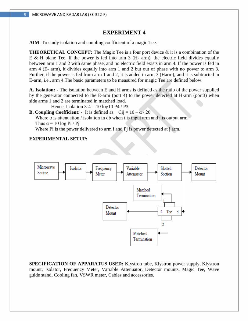
EXPERIMENTAL SETUP:
SPECIFICATION OF APPARATUS USED: Klystron tube, Klystron power supply, Klystron
mount, Isolator, Frequency Meter, Variable Attenuator, Detector mounts, Magic Tee, Wave
guide stand, Cooling fan, VSWR meter, Cables and accessories.
10 MICROWAVE AND RADAR LAB (EE-322-F)
PROCEDURE:
Measurement of Isolation and Coupling Coefficient
(1) Set the equipments as shown in fig.
(2) Remove the tunable probe and magic Tee from the slotted line and connect the detector
mount to the slotted line.
(3) Energize the microwave source for particular operation of frequency and tune the detector for
maximum output.
(4) Set any reference level of power on VSWR meter with the help of variable attenuator; gain
control knob of VSWR meter and note down the reading (let it be P3).
(5) Without changing the position of variable attenuator and gain control knob of VSWR meter,
carefully place the magic Tee after slotted line keeping H-arm to slotted line, detector to E-arm
and matched termination to arm1 and 2. Note down the reading of VSWR meter (let it be P4).
(6) Determine the isolation between port 3 and 4 as P3 – P4 in db.
(7) Determine the coupling coefficient from equation given.
(8) The same experiment may be repeated for other ports also.
(9) Repeat the same for other frequencies.
PRECAUTIONS:
1. Use fan to keep the Klystron temperature low.
2. Ensure tight connections of the apparatus
3. Avoid cross connections of the threads.
4. Use stabilized power supply.
OBSERVATION DATA:
P3 =
P4 =
Calculate Isolation and coupling coefficient using
Isolation 3-4 = 10 log10 P4 / P3
α = 10 log Pi / Pj
RESULT & COMENTS: Measured values for Isolation and coupling coefficient are I =
and α =
APPLICATION:
1. Used for isolation purpose of magic tee with other microwave components.
2. Coupling can also be done.
3. Different losses can also be calculated in microwave communication system.
11 MICROWAVE AND RADAR LAB (EE-322-F)
EXPERIMENT 5
AIM: To measure coupling coefficient, Insertion loss & Directivity of a Directional coupler.
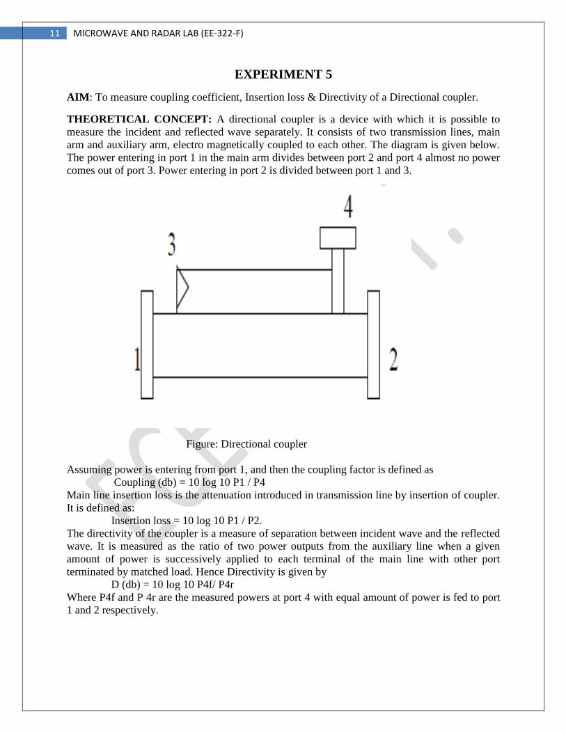
THEORETICAL CONCEPT: A directional coupler is a device with which it is possible to
measure the incident and reflected wave separately. It consists of two transmission lines, main
arm and auxiliary arm, electro magnetically coupled to each other. The diagram is given below.
The power entering in port 1 in the main arm divides between port 2 and port 4 almost no power
comes out of port 3. Power entering in port 2 is divided between port 1 and 3.
Figure: Directional coupler
Assuming power is entering from port 1, and then the coupling factor is defined as
Coupling (db) = 10 log 10 P1 / P4
Main line insertion loss is the attenuation introduced in transmission line by insertion of coupler.
It is defined as:
Insertion loss = 10 log 10 P1 / P2.
The directivity of the coupler is a measure of separation between incident wave and the reflected
wave. It is measured as the ratio of two power outputs from the auxiliary line when a given
amount of power is successively applied to each terminal of the main line with other port
terminated by matched load. Hence Directivity is given by
D (db) = 10 log 10 P4f/ P4r
Where P4f and P 4r are the measured powers at port 4 with equal amount of power is fed to port
1 and 2 respectively.
12 MICROWAVE AND RADAR LAB (EE-322-F)
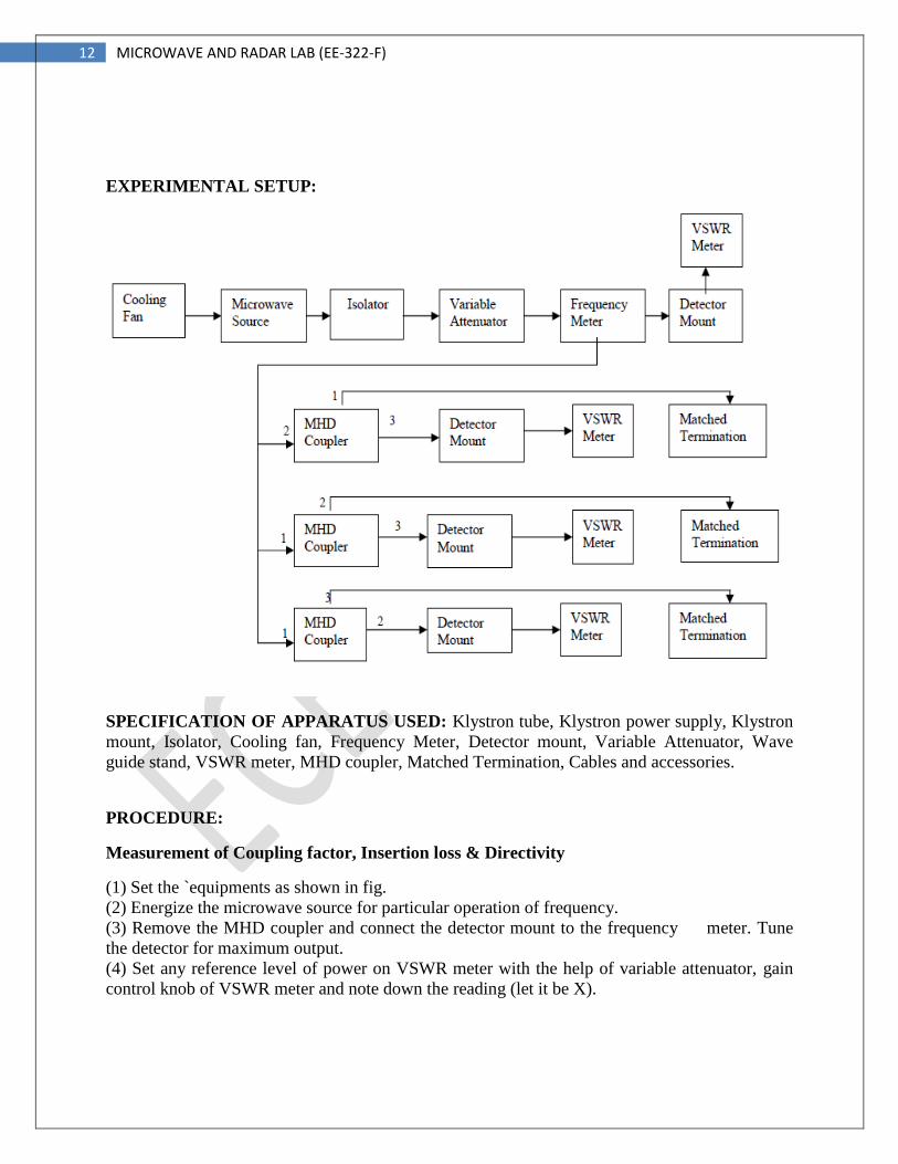
EXPERIMENTAL SETUP:
SPECIFICATION OF APPARATUS USED: Klystron tube, Klystron power supply, Klystron
mount, Isolator, Cooling fan, Frequency Meter, Detector mount, Variable Attenuator, Wave
guide stand, VSWR meter, MHD coupler, Matched Termination, Cables and accessories.
PROCEDURE:
Measurement of Coupling factor, Insertion loss & Directivity
(1) Set the `equipments as shown in fig.
(2) Energize the microwave source for particular operation of frequency.
(3) Remove the MHD coupler and connect the detector mount to the frequency meter. Tune
the detector for maximum output.
(4) Set any reference level of power on VSWR meter with the help of variable attenuator, gain
control knob of VSWR meter and note down the reading (let it be X).
13 MICROWAVE AND RADAR LAB (EE-322-F)
(5) Insert the D.C as shown in fig. With detector mount to the auxiliary port 4 and matched
termination to port 2. Without changing the position of variable attenuator and gain control knob
of VSWR meter.
(6) Note down the reading on VSWR meter (let it be Y) and calculate coupling factor using X
&Y, which will be in db.
(7) Now carefully disconnect the detector from the auxiliary port 4 and match termination from
port2 without disturbing the setup.
(8) Connect the matched termination to the aux. Port 4 and detector to port 2 and measure the
reading on VSWR meter (let it be Z).
(9) Compute insertion loss using X & Z in db.
(10) Repeat the steps from 1 to 4.
(11) Connect the D.C in the reverse direction i.e. port 2 to frequency meter side, matched
termination to port1 and detector mount to port 4, without disturbing the position of the variable
attenuator and gain control knob of VSWR meter.
(12) Note down the reading and let it be Y0 .Compute the directivity as Y- Y0.
(13) Repeat the same for other frequency.
PRECAUTIONS:
1. Use fan to keep the Klystron temperature low.
2. Ensure tight connections of the apparatus
3. Avoid cross connections of the threads.
4. Use stabilized power supply.
OBSERVATION DATA:
Calculate D, C and I using the equations as given above.
RESULT & COMENTS: The measured value for MHD coupler are
Coupling coefficient =
Insertion loss =
Directivity =
APPLICATION:
1. Different types of losses can be calculated in a microwave communication system.
2. Directivity can be easily find out.
14 MICROWAVE AND RADAR LAB (EE-322-F)
EXPERIMENT 6
AIM: To measure attenuation and insertion loss of a fixed and variable attenuator.
THEORETICAL CONCEPT: The attenuators are two port bidirectional devices which
attenuates some power when inserted into the transmission line.
Attenuation A (db) == 10 log P1/P2
Where, P1 = Power absorbed or detected by the load without the attenuator in the line. P2 =
Power absorbed/detected by the load with attenuator in the line. The attenuators consist of a
rectangular wave guide with a resistive vane inside it to absorb microwave power according to
their position with respect to side wall of the waveguide. An electric field is maximum at centre
in TEIO mode; the attenuation will be maximum if the vane is placed at centre of the waveguide.
Moving from centre towards the side wall, attenuation decreases in the fixed attenuator, the vane
position is fixed where as in variable attenuator, its position can be changed by the help of
micrometer or by other methods.
Following characteristics of attenuators can be studied:
1. Input VSWR.
2. Insertion loss (in case of variable attenuator).
3. Amount of attenuation offered into the lines.
4. Frequency sensitivity, i.e., variation of attenuation at any fixed position of vane and frequency
is changed.
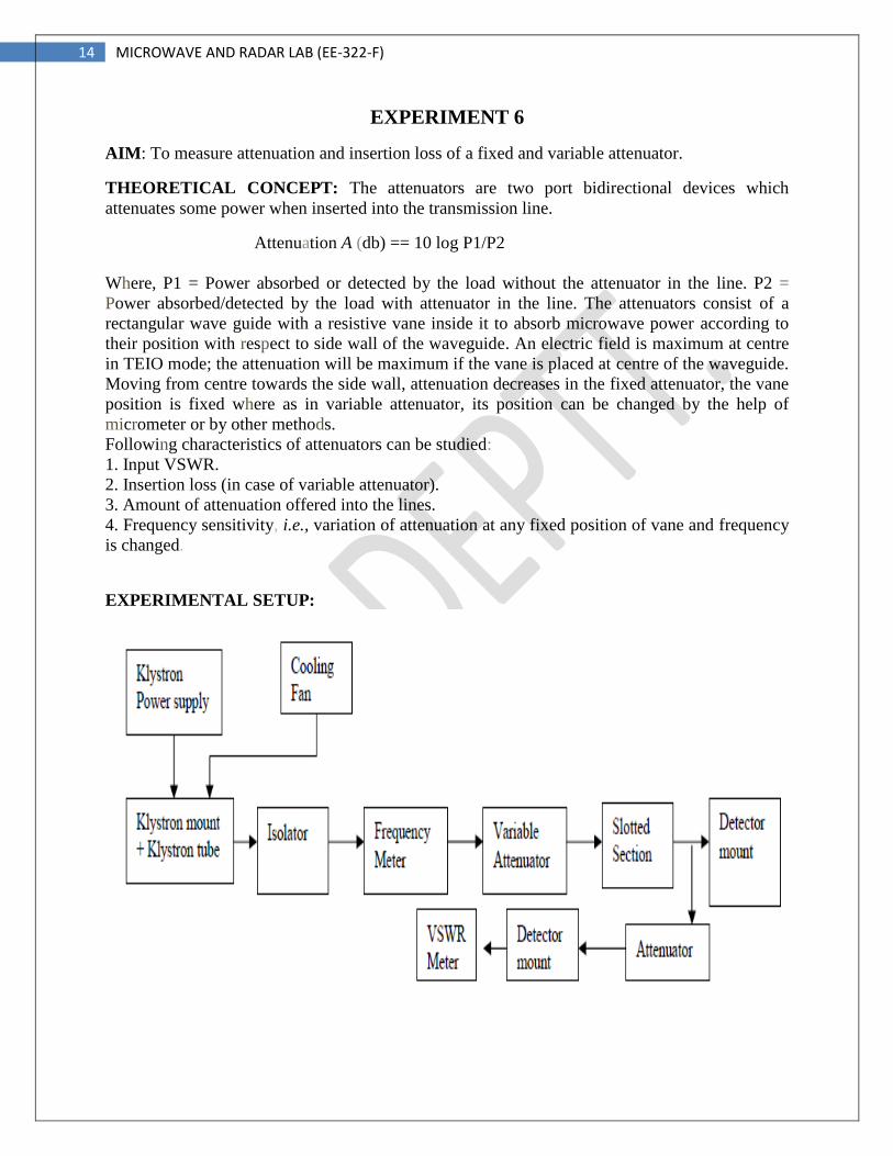
EXPERIMENTAL SETUP:
15 MICROWAVE AND RADAR LAB (EE-322-F)
SPECIFICATION OF APPARATUS USED: Microwave source, Isolator, Frequency meter,
Variable attenuator, Slotted line, Tunable probe, Detector mount, Matched termination, VSWR
meter, test fixed and variable attenuator and Accessories.
PROCEDURE:
Insertion Loss/Attenuation Measurement
1. Remove the tunable probe, attenuator and matched termination from the slotted section in the
above set up.
2. Connect the detector mount to the slotted line, and tune the detector mount also for maximum
deflection on VSWR meter (Detector mount's output should be connected to VSWR meter).
3. Set any reference level on the VSWR meter with the help of variable attenuator (not test
attenuator) and gain control knob of VSWR meter. Let it be P1.
4. Carefully disconnect the detector mount from the slotted line, without disturbing any position
on the set up. Place the test variable attenuator to the slotted line and detector mount to other port
of test variable attenuator. Keep the micrometer reading of test variable attenuator to zero and
record the reading of VSWR meter. Let it be P2. Then the insertion loss of test attenuator will be
P1 – P2 db.
5. For measurement of attenuation of fixed and variable attenuator, after step 4 of above
measurement, carefully disconnect the detector mount from the slotted line without disturbing
any position obtained up to step 3. Place the test attenuator to the slotted line and detector mount
to the other port of test attenuator. Record the reading of VSWR meter. Let it be P3. Then the
attenuation value of fixed attenuator or attenuation value of variable attenuator for particular
position of micrometer reading will be PI - P3 db.
6. In case of variable attenuator, change the micrometer reading and record the VSWR meter
reading. Find out attenuation value for different position of Micrometer reading and plot a graph.
7. Now change the operating frequency and whole step should be repeated for finding frequency
sensitivity of fixed and variable attenuator.
PRECAUTIONS:
1. Use fan to keep the Klystron temperature low.
2. Ensure tight connections of the apparatus
3. Avoid cross connections of the threads.
4. Use stabilized power supply.
RESULT & COMENTS: The measured value of attenuation and insertion loss of a fixed and
variable attenuator is
APPLICATION:
1. Different attenuators can be used for microwave signal transmission.
2. Losses can be calculated for fixed as well as variable attenuator.
16 MICROWAVE AND RADAR LAB (EE-322-F)
EXPERIMENT 7
AIM: To measure isolation and insertion loss of a three port Circulators/Isolator.
THEORETICAL CONCEPT:
ISOLATOR: - The isolator is a two-port device with small insertion loss in forward direction
and a large in reverse attenuation.
CIRCULATOR: - the circulator is a multi port junction that permits transmission
in certain ways. A wave incident in port 1 is coupled to port 2 only; a wave incident at port 2 is
coupled to port3 only and so on. Following is the basic parameters of isolator and circulator for
study.
A. Insertion loss: - The ratio of power supplied by a source to the input port to the power
detected by a detector in the coupling arm, i.e., output arm with other port terminated in the
matched load, is defined as insertion loss or forward loss.
B. Isolation: - It is the ratio of power fed to input arm to the input power detected at not coupled
port with other port terminated in the matched load.
C. Input VSWR: - The input VSWR of an isolator or circulator is the ratio of voltage maximum
to voltage minimum of the standing wave existing on the line, when one port of it terminates the
line and others have matched termination.
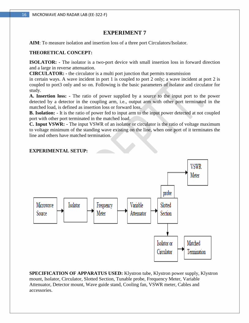
EXPERIMENTAL SETUP:
SPECIFICATION OF APPARATUS USED: Klystron tube, Klystron power supply, Klystron
mount, Isolator, Circulator, Slotted Section, Tunable probe, Frequency Meter, Variable
Attenuator, Detector mount, Wave guide stand, Cooling fan, VSWR meter, Cables and
accessories.
17 MICROWAVE AND RADAR LAB (EE-322-F)
PROCEDURE:
(a) Input VSWR Measurement:
(1) Set up the components and equipments as shown above with input port of isolator or
circulator towards slotted line and matched load on other ports of it.
(2) Energize the microwave source for particular operation of frequency.
(3) With the help of slotted line, probe and VSWR meter, find out SWR of the isolator or
circulator as describe earlier for low and medium SWR measurements.
(4) The above procedure can be repeated for other ports or for other frequencies.
(b) Measurement of Insertion loss & Isolation:
(1) Remove the probe and isolator or circulator from slotted line and connect the detector mount
to the slotted section. The output of the detector mount should be connected with VSWR meter.
(2) Energize the microwave source for max. Output for a particular frequency of operation. Tune
the detector mount for maximum output in VSWR meter.
(3) Set any reference level of power in VSWR meter with the help of variable attenuator, gain
control knob of VSWR meter and note down the reading (let it be P1).
(4) Carefully remove the detector mount from slotted line without disturbing the position of set
up. Insert the isolator / circulator between slotted line and detector mount. Keeping input port to
slotted line and detector at its output port. A matched termination should be placed at third port
in case of circulator.
(5) Record the readings in the VSWR meter. If necessary change range – db switch to high or
lower position and taking 10 db changes for one set change of switch position (let it be P2).
(6) Compute insertion loss on P1-P2 in db.
(7) For measurement of isolation, the isolator or circulator has to be connected reverse, i.e.,
output port to slotted line and detector to input port with other port terminated by matched
termination. After setting a reference level without isolator or circulator in the set up as described
in insertion loss measurement. Let same P1 level is set.
(8) Record the reading of VSWR meter after inserting the isolator or circulator (let it be P3).
(9) Compute isolation as P1 – P3 in db.
(10) The same experiment can be done for other ports of circulator.
(11) Repeat the same for other frequency.
PRECAUTIONS:
1. Use fan to keep the Klystron temperature low.
2. Ensure tight connections of the apparatus
3. Avoid cross connections of the threads.
4. Use stabilized power supply.
RESULT & COMENTS: Measured values are follows:
VSWR =
Insertion loss =
Isolation =
APPLICATION:
1. Used for calculation of losses in circulators and isolators.
18 MICROWAVE AND RADAR LAB (EE-322-F)
EXPERIMENT 8
AIM: To measure the standing wave ratio and reflection coefficient in a microwave transmission
line.
THEORETICAL CONCEPT: The electromagnetic field at any point of termination line may
be considered as the sum of two traveling wave, the ‘incident wave’ propagates from generator
and reflected wave propagates towards the generator. The reflected wave is setup by reflection of
incident wave from a discontinuity on the line or from load impedance. The presence of two
traveling waves, gives rise to standing wave along the line. The maximum field strength is found
where two waves are in phase and minimum where the two waves add in opposite phase. The
distance between two successive minimum (or maximum) is half the guide wavelength on the
line. The ratio of electric field strength of reflected and incident wave is called reflection
coefficient. The voltage standing wave ratio is defined as ratio between maximum or minimum
field strength along the line. Hence, VSWR, S = Emax. / Emin
Reflection Coefficient, ρ = Er / Ei = (Z – Zo) /(Z + Zo)
Where Z is the impedance at a point on line, Zo is characteristic impedance. The above equation
gives following equation:
|ρ| = S -1
S+1
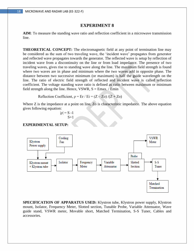
EXPERIMENTAL SETUP:
SPECIFICATION OF APPARATUS USED: Klystron tube, Klystron power supply, Klystron
mount, Isolator, Frequency Meter, Slotted section, Tunable Probe, Variable Attenuator, Wave
guide stand, VSWR meter, Movable short, Matched Termination, S-S Tuner, Cables and
accessories.
19 MICROWAVE AND RADAR LAB (EE-322-F)
PROCEDURE:
(1) Set the components and equipments as shown in block diagram.
(2) Keep variable attenuator at maximum position.
(3) Keep the control knobs of Klystron Power Supply as below:
Meter Switch - ‘OFF’
Mod Switch - AM
Beam voltage knob - Fully anti-clockwise
Reflector voltage - Fully clockwise
AM- amplitude and
Frequency knob - Mid position.
(4) Keep the control knob of VSWR meter as below:
Meter Switch - Normal
Input Switch - Low Impedance
Range db Switch - 40 / 50 db
(5) ‘ON’ the Klystron Power Supply, VSWR meter and Cooling Fan
(6) Turn the meter switch of power supply to beam voltage position and set beam voltage at
300V with the help of beam voltage knob.
(7) Adjust the reflector voltage to get some deflection in VSWR meter.
(8) Maximize the deflection with AM amplitude and frequency control knob of power supply.
(9) Tune the plunger, reflector voltage, and probe for maximum deflection in VSWR meter.
(10) Move the probe along the slotted line, the deflection will change.
MEASUREMENT OF LOW AND MEDIUM VSWR
(1) Move the probe along with slotted line to get maximum deflection in VSWR meter.
(2) Adjust the VSWR meter gain control knob or variable attenuator until the meter indicates 1
on normal SWR scale.
(3) Keep all the control knob as it is, move probe to next minimum position and read the VSWR
on scale and record it.
(4) Repeat the above step for change of S-S Tuner probe depth and record the corresponding
SWR.
PRECAUTIONS:
1. Use fan to keep the Klystron temperature low.
2. Ensure tight connections of the apparatus
3. Avoid cross connections of the threads.
4. Use stabilized power supply.
RESULT & COMENTS: Standing wave ratio and Reflection coefficient are measured & equal
to SWR = ρ =
APPLICATION:
1. SWR and reflection coefficient are important parameters in a microwave communication
system. Hence, these can be easily find out.
20 MICROWAVE AND RADAR LAB (EE-322-F)
EXPERIMENT 9
AIM: To measure the frequency of a microwave source and demonstrate relationship among
guide dimensions, free space wavelength and guide wavelength.
THEORETICAL CONCEPT: For dominant TE 10 mode in rectangular wave guides λo, λg
and λc are related as below
Where, λo = free space wavelength
λg = Guide wavelength
λc = Cut off wavelength
For dominant TE 10 mode λ c = 2a where a is broad dimension of wave guide. The following
relationship can be proved.
C = f λ
Where, C is velocity of light and f is frequency.
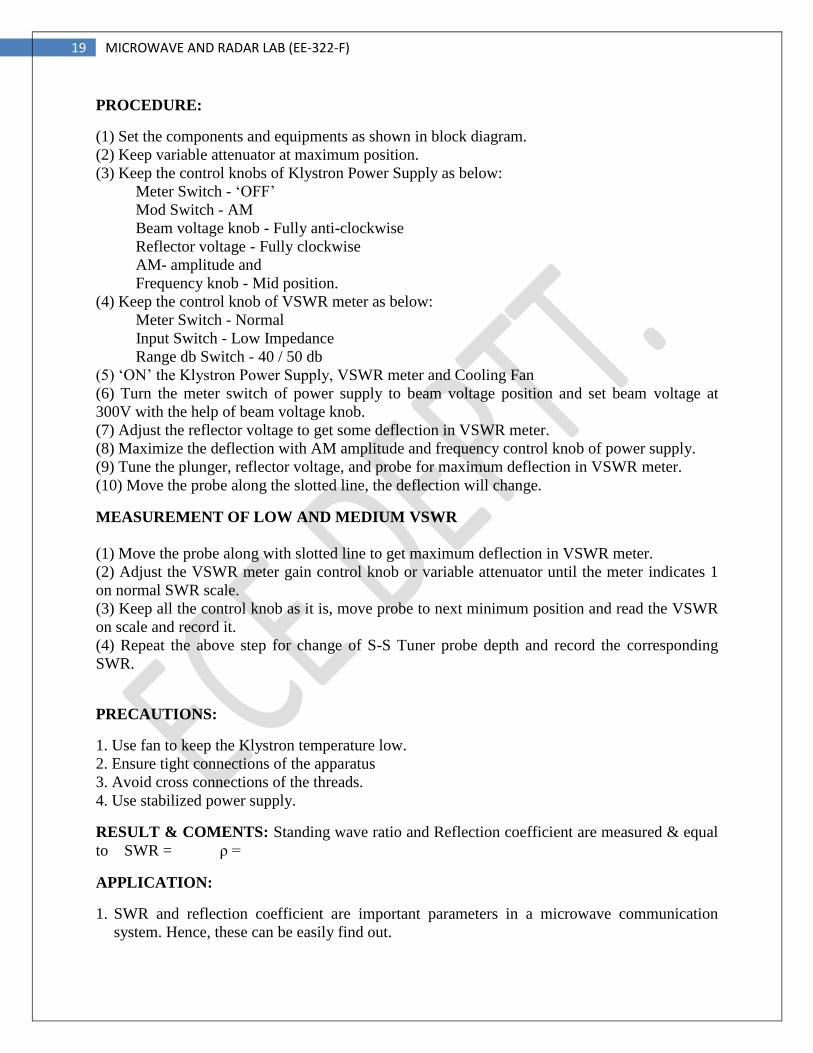
EXPERIMENTAL SETUP:
SPECIFICATION OF APPARATUS USED: Klystron tube, Klystron power supply, Klystron
mount, Isolator, Frequency Meter, Slotted section, Tunable Probe, Variable Attenuator, Wave
guide stand, VSWR meter, Movable Short / Matched Termination, Cables and accessories.
21 MICROWAVE AND RADAR LAB (EE-322-F)
PROCEDURE:
(1) Set the components and equipments as shown in block diagram.
(2) Initially set the variable attenuator for maximum position.
(3) Keep the control knobs of Klystron Power Supply as below:
Meter Switch - ‘OFF’
Mod Switch - AM
Beam voltage knob - Fully anti-clockwise
Reflector voltage - Fully clockwise
(4) Keep the control knob of VSWR meter as below:
Meter Switch - Normal
Input Switch - Low Impedance
(5) ‘ON’ the Klystron Power Supply, VSWR meter and Cooling Fan.
(6) Turn the meter switch of power supply to beam voltage position and set beam voltage at
300V with the help of beam voltage knob.
(7) Adjust the reflector voltage to get some deflection in VSWR meter.
(8) Maximize the deflection with AM amplitude and frequency control knob of power supply.
(9) Tune the plunger, reflector voltage, and probe for maximum deflection in VSWR meter.
(10) Tune the frequency meter knob to get the ‘dip’ on the VSWR scale and note down the
frequency directly from frequency meter.
(11) Replace the termination with movable short, and detune the frequency meter.
(12) Move probe along with the slotted line, the deflection in VSWR meter will vary. Move the
probe to a minimum deflection position, to get accurate reading, it is necessary to increase the
VSWR meter range db switch to higher position. Note and record the probe position.
(13) Move the probe to next minimum position and record the probe position again.
(14) Calculate the guide length wave as twice the distance between successive minimum
positions obtained as above.
(15) Measure the wave guide inner broad dimension ‘a’ which will be around 22.86 mm for X-
band.
(16) Calculate the frequency by following equation.
(17) Verify with frequency obtained by frequency meter.
(18) Above experiment can be verified at different frequencies.
PRECAUTIONS:
1. Use fan to keep the Klystron temperature low.
2. Ensure tight connections of the apparatus
3. Avoid cross connections of the threads.
4. Use stabilized power supply.
RESULT & COMENTS: Measured frequency f =
APPLICATION:
1. Used for measurement of frequency of unknown microwave source.
22 MICROWAVE AND RADAR LAB (EE-322-F)
EXPERIMENT 10
AIM: To measure the impedance of unknown load.
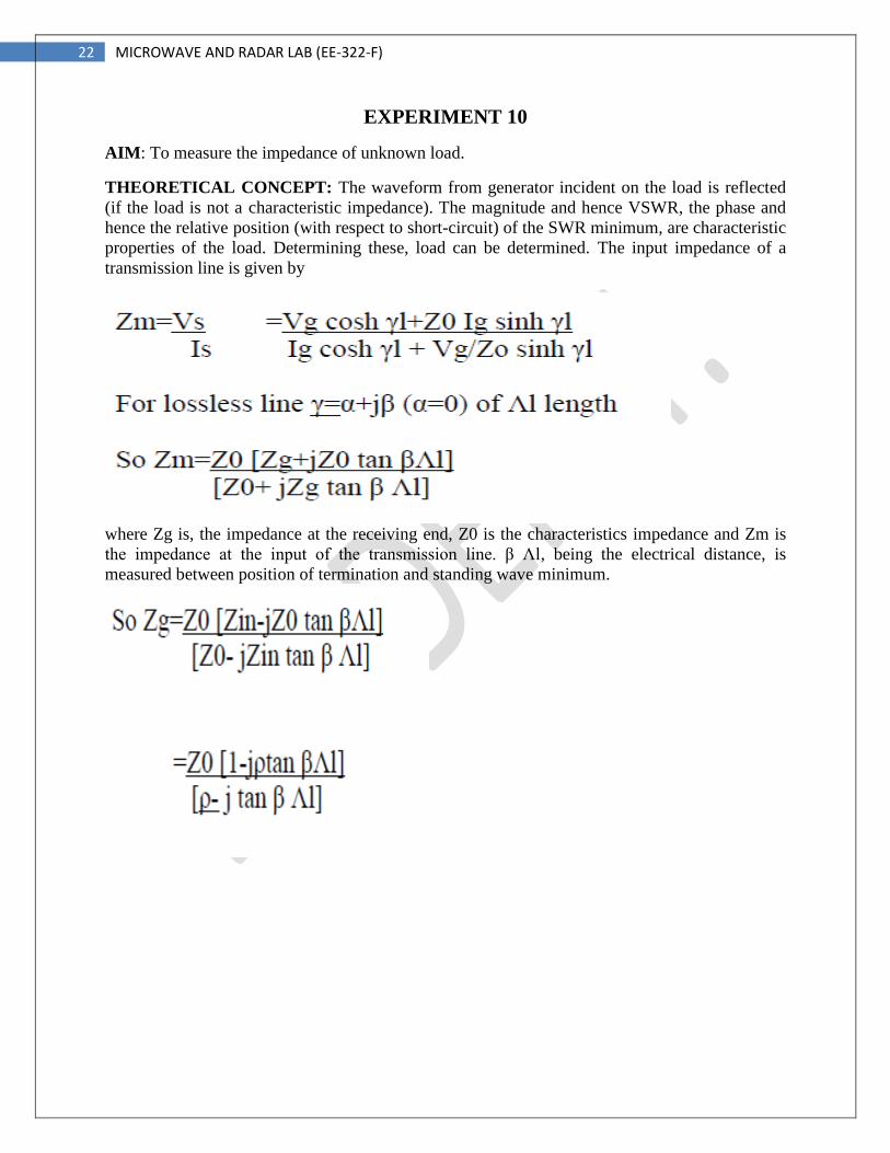
THEORETICAL CONCEPT: The waveform from generator incident on the load is reflected
(if the load is not a characteristic impedance). The magnitude and hence VSWR, the phase and
hence the relative position (with respect to short-circuit) of the SWR minimum, are characteristic
properties of the load. Determining these, load can be determined. The input impedance of a
transmission line is given by
where Zg is, the impedance at the receiving end, Z0 is the characteristics impedance and Zm is
the impedance at the input of the transmission line. β Λl, being the electrical distance, is
measured between position of termination and standing wave minimum.
23 MICROWAVE AND RADAR LAB (EE-322-F)
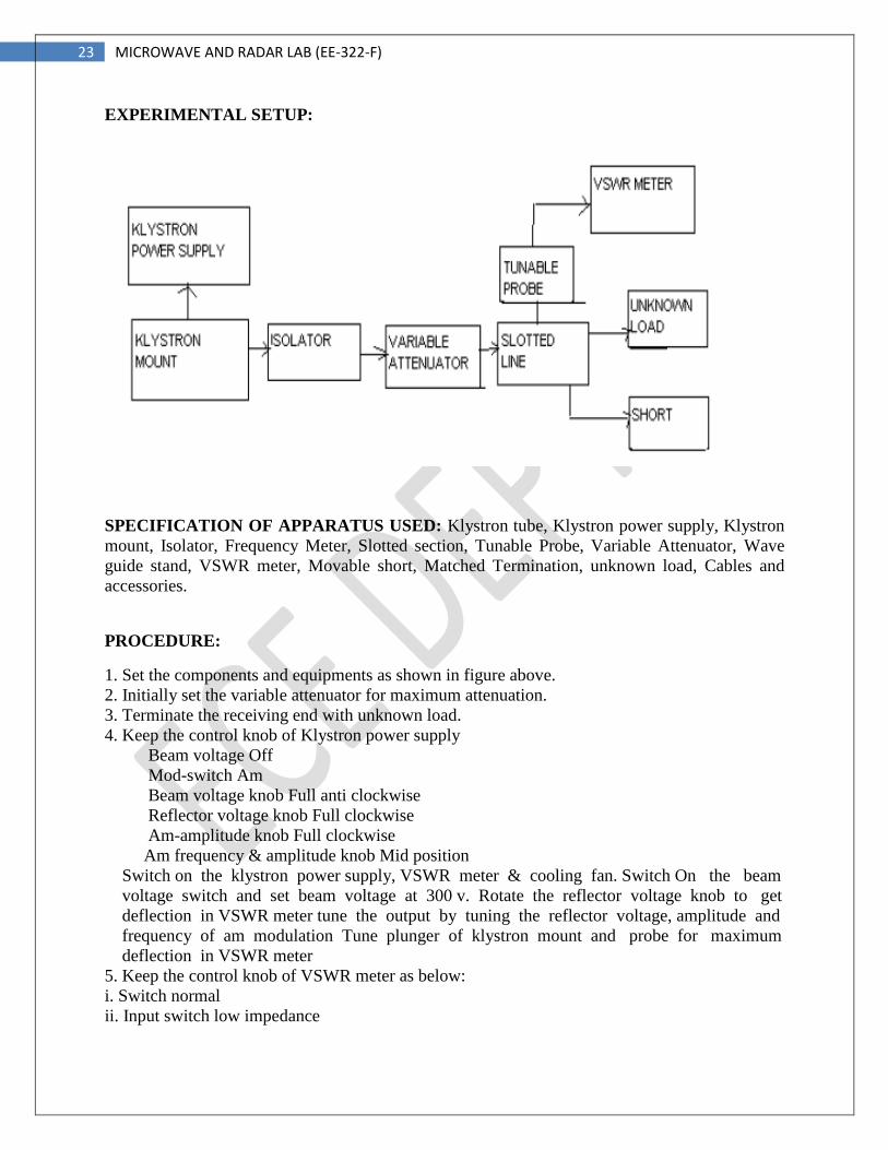
EXPERIMENTAL SETUP:
SPECIFICATION OF APPARATUS USED: Klystron tube, Klystron power supply, Klystron
mount, Isolator, Frequency Meter, Slotted section, Tunable Probe, Variable Attenuator, Wave
guide stand, VSWR meter, Movable short, Matched Termination, unknown load, Cables and
accessories.
PROCEDURE:
1. Set the components and equipments as shown in figure above.
2. Initially set the variable attenuator for maximum attenuation.
3. Terminate the receiving end with unknown load.
4. Keep the control knob of Klystron power supply
Beam voltage Off
Mod-switch Am
Beam voltage knob Full anti clockwise
Reflector voltage knob Full clockwise
Am-amplitude knob Full clockwise
Am frequency & amplitude knob Mid position
Switch on the klystron power supply, VSWR meter & cooling fan. Switch On the beam
voltage switch and set beam voltage at 300 v. Rotate the reflector voltage knob to get
deflection in VSWR meter tune the output by tuning the reflector voltage, amplitude and
frequency of am modulation Tune plunger of klystron mount and probe for maximum
deflection in VSWR meter
5. Keep the control knob of VSWR meter as below:
i. Switch normal
ii. Input switch low impedance
24 MICROWAVE AND RADAR LAB (EE-322-F)
iii. Range db switch 40db
iv. Gain control knob fully clockwise
6. Connect detector output to SWR meter.
7. Adjust the square wave modulation frequency to approximately 1 KHz.
8. Tune the detector by adjusting short plunger for maximum meter deflection
9. Move the probe along slotted line, adjust it at standing wave minimum. Record the probe
position as X, (this is the position of reference minimum) and next successive minimum position
as X2.
10. Replace load by short circuit termination and move the probe carriage to new standing wave
minimum and record the probe position as Xs (This is known as position of reference plane)
11. Find the shift minima (Xs·X2 or Xs·X.). It will be positive if minimum is shifted towards
load (i.e., for inductive load) and negative if minimum is shifted towards generator (for
capacitive load). Shift in minimum for different loads can be easily known from the standing
wave patterns given below.
12. Convert the shift in wavelength units, i.e., (X,X,). Wavelengths.
13. Position on minimum can be known more accurately if it is taken as midpoint of positions of
equal responses on either side of minimum.
PRECAUTIONS:
1. Use fan to keep the Klystron temperature low.
2. Ensure tight connections of the apparatus
3. Avoid cross connections of the threads.
4. Use stabilized power supply.
RESULT & COMENTS: The impedance of unknown load is
APPLICATION:
1. Used for impedence matching for good signal transmission.