Embed Size (px)
Citation preview

MicroTech II™ Unit Ventilator Controlsfor Daikin Classroom Unit Ventilators
Before beginning installation, please read this publication in its entirety.Develop a thorough understanding before starting the installation procedure. This manual is to be used as a guide. Each installation is unique, so only general topics are covered. The order in which topics are covered may not be those required for the actual installation.
Installation Manual IM 747-1
Group: Unit Ventilator Part Number: 106506202 Date: October 2013
IMPORTANT!
Used with Daikin Models: Vertical Floor - AVS, AVV, AVB, and AVRHorizontal Ceiling - AHF, AHB, AHV and AHRSelf-Contained Vertical Floor - AZQ, AZU, AZR, AEQ, ARQ, ERQ, GRQ
©2013 Daikin Applied • www.DaikinAP.com • (800) 432-1342

Page 2 of 36 MicroTech II Unit Ventilator Controls IM 747-1
ContentsSafety Information ....................................................... 3Introduction .................................................................. 4 General Information ................................................ 4 General Description ................................................ 4 Basic Component Data ........................................... 5 Unit Ventilator Controller (UVC) .............................. 5Unit Ventilator Controller (UVC) ..............................5-6 Expansion Board (EXP) .......................................... 6 Local User Interface (LUI) ....................................... 7 Plug-in LonMark Space Comfort Controller (SCC)
Communication Module (Optional) ......................... 7 Plug-in BACnet® MS/TP Communication Module
(Optional) ................................................................ 7Plug-In Communication Modules ............................7-8 Plug-in Metasys® N2 Open Communication Module
(Optional) ................................................................ 8 Master-Slave Communication Modules (Optional) . 8 Master / Slave Control (Optional) ............................ 8 Temperature Sensor ............................................... 9 Humidity Sensor (Optional) ..................................... 9Sensors ........................................................................ 9Actuators .................................................................... 10 Carbon Dioxide (CO2) Sensor (Optional) for
Demand Controlled Ventilation (DCV) .................. 10 Face & Bypass Damper Actuator (Optional) ......... 10 Outdoor Air/Return Air Damper (OAD) Actuator .... 10 2-Position End-of-Cycle (EOC) Valves (Optional) . 11Valves .................................................................... 11-12 WSHP 2-Position Motorized Water Valves
(Optional) .............................................................. 12 Modulating Valve Actuators (Optional) .................. 12 Time Clock with Stand-Alone Unit Ventilators
(Optional) .............................................................. 12Time Clock ................................................................. 13Electrical Wiring Connections .............................14-17 Make Electrical Wiring Connections ..................... 14 Field Wiring Harness Locations ............................ 14 ElectroMechanical Unit Type (Optional for AR, ER
& GR) - Wiring Connection Location ..................... 17
Remote Mounted Sensors ...................................18-24 Field Wiring Remote Mounted Temperature
Sensor ................................................................... 18 Remote Wall Mounted Sensors (Optional) ............ 18 When Using A Remote Wall Mounted Temperature
Sensor ................................................................... 19 Installation ............................................................. 20 Parts Included - All Models ................................... 20 Parts Included - 111048102 and 111048103
Only ....................................................................... 20 Special Tools Needed ........................................... 20 Mounting ............................................................... 20 Performing Wallbox Mounting ............................... 20 Performing Surface Mounting Using Large Base .. 20 Performing Surface Mounting Using Small Base .. 21 Wiring .................................................................... 22 Setup and Adjustments ......................................... 22 Repairs and Replacement .................................... 22 External Input Option Wiring ................................. 22 External Output Option Wiring .............................. 23Communication Module Wiring ................................ 25 Split-System Condensing Unit Signal Wiring (Model
AVS, AVV, AVR, AHF, AHV, AHR) .......................... 25 Communication Module Wiring ............................. 25UVC Inputs and Outputs Data .............................26-31 Software Model 0 - Air Source Heat Pump with
Electric Heat .......................................................... 26 Software Models 2 and 3 - Water Source Heat
Pump with or without Electric Heat ....................... 26 Software Models 4 – DX Cooling w/Electric Heat, 5
– DX Cooling Only, and 6 – Electric Heat Only ..... 27 Software Models 7 – DX Cooling w/Wet Heat -
Valve Control, and 8 – DX Cooling w/Wet Heat - F&BP Damper ....................................................... 28
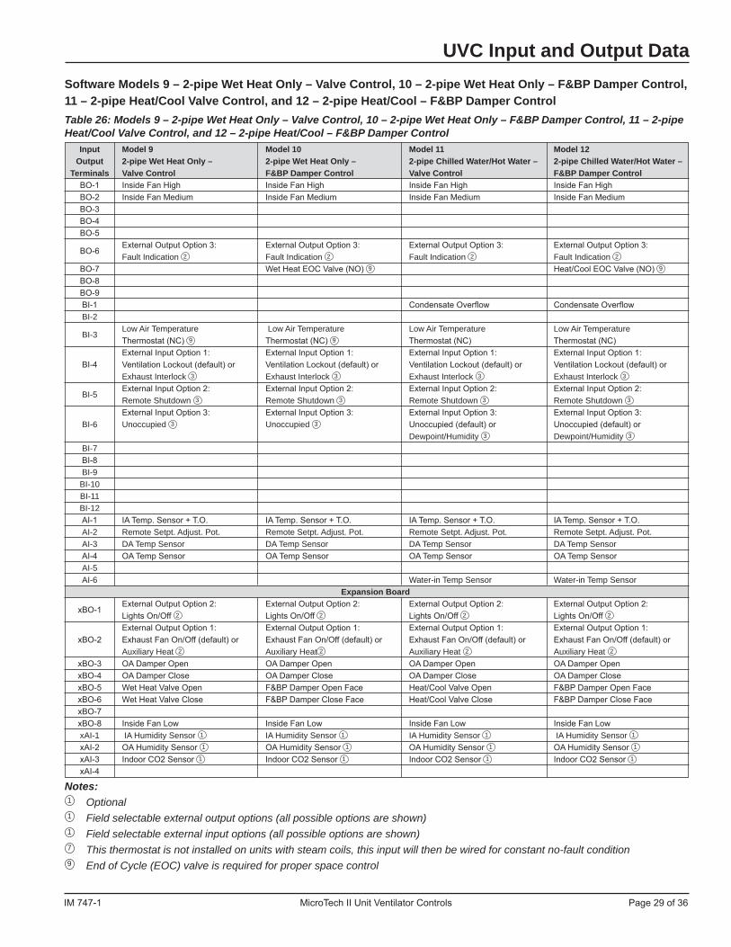
Software Models 9 – 2-pipe Wet Heat Only – Valve Control, 10 – 2-pipe Wet Heat Only – F&BP Damper Control, 11 – 2-pipe Heat/Cool Valve Control, and 12 – 2-pipe Heat/Cool – F&BP Damper Control .. 29
Software Models 13 – 4-pipe Heat/Cool – Valve Control, and 14 – 4-pipe Heat/Cool – F&BP Damper Control ................................................................. 30
Software Models 15 – 2-pipe Cooling Only – Valve Control, 16 – 2-pipe Cooling Only – F&BP Damper Control, 17 – 2-pipe Cooling - Valve Control w/Electric Heat, and 18 – 2-pipe Cooling - F&BP Damper Control w/Electric Heat ........................... 31
UVC Configuration Parameters ...........................32-35

IM 747-1 MicroTech II Unit Ventilator Controls Page 3 of 36
Safety InformationFollow all safety codes. Wear safety glasses and work gloves. Have a fire extinguisher available. Follow all warnings and cautions in these instructions and attached to the unit. Consult applicable local building codes and National Electrical Codes (NEC) for special requirements.Recognize safety information. When you see a safety symbol on the unit or in these instructions, be alert to the potential for personal injury or death. Understand the meanings of the words DANGER, WARNING, and CAUTION. DANGER identifies the most serious hazards that will result in death or severe personal injury; WARNING means the hazards can result in death or severe personal injury; CAUTION identifies unsafe practices that can result in personal injury or product and property damage. Improper installation, adjustment, service, maintenance, or use can cause explosion, fire, electrical shock, or other condi-tions which may result in personal injury or property dam-age. This product must be installed only by personnel with the training, experience, skills, and applicable licensing that makes him/her “a qualified professional HVACR installer.”
Disconnect all electrical power before servicing unit to
prevent injury or death due to electrical shock.
Hazardous voltage! Disconnect all electric power including remote disconnects before servicing. Failure to disconnect power before servicing can cause severe personal injury or death.
Use copper conductors only. Unit terminals are designed to accept other types of conductors. Failure to do so may cause damage to the equipment.
Electric shock hazard. Can cause personal injury, or death, or equipment damage. This equipment must be properly grounded. Connections and service to the MicroTech II control panel must
be performed only by personnel that are knowledgeable in the operation of the equipment being controlled.
If the unit ventilator is to be used for temporary heating or cool-ing, the unit must first be properly commissioned. Failure to com-ply with this requirement will void the warranty.
Static sensitive components. A static discharge while handling electronic circuit boards can cause damage to the components. Discharge any static electrical charge by touching the bare met-
al inside the main control panel before performing any service work.
Never unplug any cables, circuit board terminal blocks, relay modules, or power plugs while power is applied to the panel.
For proper space control, and a more trouble free unit operation, it is important that End-of-Cycle (EOC) valves be used in all face & bypass damper equipped unit ventilators. An EOC valve is required for the wet heat coil in any unit ventilator that combines both a refrigerant coil and a wet heat coil. Use an EOC valve on all wet heat coils to minimize the potential for overheating.
For proper space control, and a more trouble free unit operation, it is important that an occupancy control means be used such
that the unit is placed into unoccupied mode during regular low load conditions such as nighttime, weekends and holidays.
Extreme temperature hazard. Can cause damage to system components. This MicroTech II controller is designed to operate in ambient temperatures from -40°F to 158°F. It can be stored in ambient temperatures from -65°F to 176°F. The controller is designed to operate in a 10% to 90% RH (non-condensing) and be stored in
a 5% to 95% RH (non-condensing) environment.
This equipment generates, uses, and can radiate radio frequen-cy energy and, if not installed and used in accordance with this
instruction manual, may cause interference to radio communications. It has been tested and found to comply with
the limits for a Class A digital device, pursuant to part 15 of the FCC rules. These limits are designed to provide reasonable pro-tection against harmful interference when the equipment is
operated in a normal commercial environment. Operation of this equipment in a residential area is likely to cause harmful inter-
fence in which case the user will be required to correct the inter-ference at his own expense.
McQuay International disclaims any liability resulting from any interference or for the correction thereof.
! DANGER
Safety Information
! WARNING
! CAUTION
! WARNING
! WARNING
! CAUTION
! CAUTION
! CAUTION
! CAUTION
NOTICE
Page 4 of 36 MicroTech II Unit Ventilator Controls IM 747-1
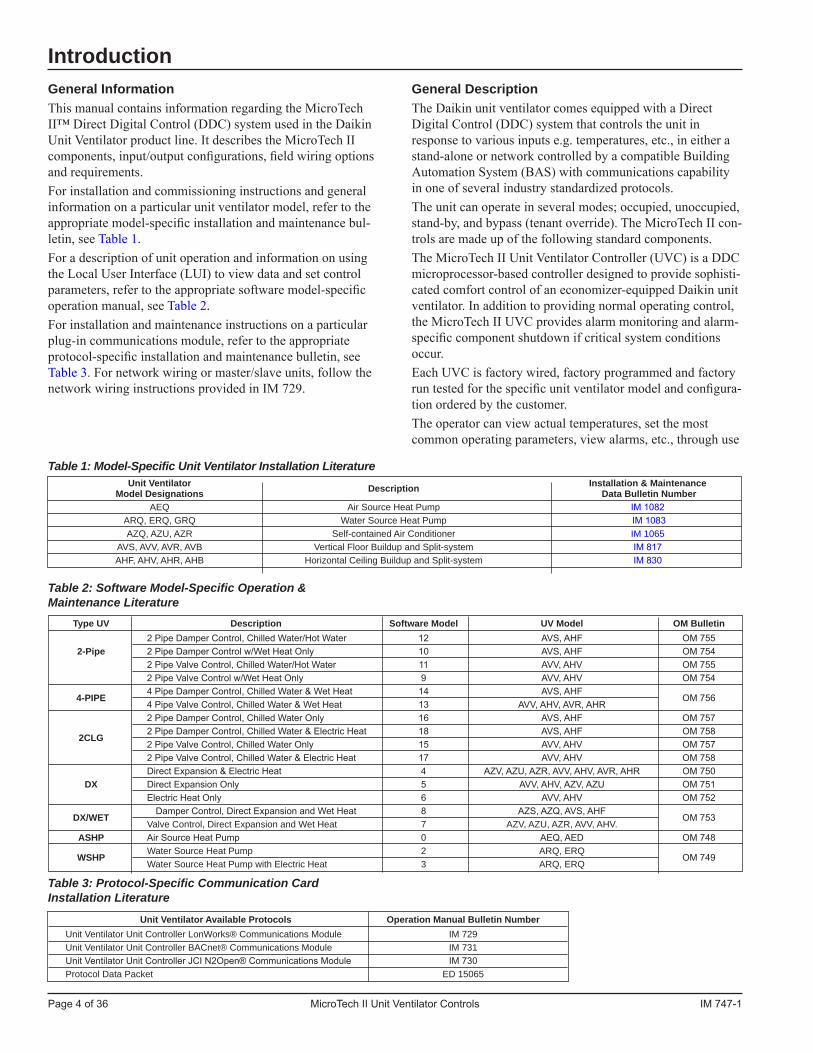
General InformationThis manual contains information regarding the MicroTech II™ Direct Digital Control (DDC) system used in the Daikin Unit Ventilator product line. It describes the MicroTech II components, input/output configurations, field wiring options and requirements. For installation and commissioning instructions and general information on a particular unit ventilator model, refer to the appropriate model-specific installation and maintenance bul-letin, see Table 1.For a description of unit operation and information on using the Local User Interface (LUI) to view data and set control parameters, refer to the appropriate software model-specific operation manual, see Table 2.For installation and maintenance instructions on a particular plug-in communications module, refer to the appropriate protocol-specific installation and maintenance bulletin, see Table 3. For network wiring or master/slave units, follow the network wiring instructions provided in IM 729.
Table 1: Model-Specific Unit Ventilator Installation Literature
Table 2: Software Model-Specific Operation & Maintenance Literature
Table 3: Protocol-Specific Communication Card Installation Literature
Introduction
Unit Ventilator Installation & Maintenance Model Designations Description Data Bulletin Number AEQ Air Source Heat Pump IM 1082 ARQ, ERQ, GRQ Water Source Heat Pump IM 1083 AZQ, AZU, AZR Self-contained Air Conditioner IM 1065 AVS, AVV, AVR, AVB Vertical Floor Buildup and Split-system IM 817 AHF, AHV, AHR, AHB Horizontal Ceiling Buildup and Split-system IM 830
Type UV Description Software Model UV Model OM Bulletin 2 Pipe Damper Control, Chilled Water/Hot Water 12 AVS, AHF OM 755 2-Pipe 2 Pipe Damper Control w/Wet Heat Only 10 AVS, AHF OM 754 2 Pipe Valve Control, Chilled Water/Hot Water 11 AVV, AHV OM 755 2 Pipe Valve Control w/Wet Heat Only 9 AVV, AHV OM 754
4-PIPE 4 Pipe Damper Control, Chilled Water & Wet Heat 14 AVS, AHF
OM 756 4 Pipe Valve Control, Chilled Water & Wet Heat 13 AVV, AHV, AVR, AHR 2 Pipe Damper Control, Chilled Water Only 16 AVS, AHF OM 757
2CLG 2 Pipe Damper Control, Chilled Water & Electric Heat 18 AVS, AHF OM 758
2 Pipe Valve Control, Chilled Water Only 15 AVV, AHV OM 757 2 Pipe Valve Control, Chilled Water & Electric Heat 17 AVV, AHV OM 758 Direct Expansion & Electric Heat 4 AZV, AZU, AZR, AVV, AHV, AVR, AHR OM 750 DX Direct Expansion Only 5 AVV, AHV, AZV, AZU OM 751 Electric Heat Only 6 AVV, AHV OM 752
DX/WET Damper Control, Direct Expansion and Wet Heat 8 AZS, AZQ, AVS, AHF
OM 753 Valve Control, Direct Expansion and Wet Heat 7 AZV, AZU, AZR, AVV, AHV. ASHP Air Source Heat Pump 0 AEQ, AED OM 748
WSHP Water Source Heat Pump 2 ARQ, ERQ
OM 749 Water Source Heat Pump with Electric Heat 3 ARQ, ERQ
General DescriptionThe Daikin unit ventilator comes equipped with a Direct Digital Control (DDC) system that controls the unit in response to various inputs e.g. temperatures, etc., in either a stand-alone or network controlled by a compatible Building Automation System (BAS) with communications capability in one of several industry standardized protocols.The unit can operate in several modes; occupied, unoccupied, stand-by, and bypass (tenant override). The MicroTech II con-trols are made up of the following standard components.The MicroTech II Unit Ventilator Controller (UVC) is a DDC microprocessor-based controller designed to provide sophisti-cated comfort control of an economizer-equipped Daikin unit ventilator. In addition to providing normal operating control, the MicroTech II UVC provides alarm monitoring and alarm-specific component shutdown if critical system conditions occur.Each UVC is factory wired, factory programmed and factory run tested for the specific unit ventilator model and configura-tion ordered by the customer.The operator can view actual temperatures, set the most common operating parameters, view alarms, etc., through use
Unit Ventilator Available Protocols Operation Manual Bulletin Number Unit Ventilator Unit Controller LonWorks® Communications Module IM 729 Unit Ventilator Unit Controller BACnet® Communications Module IM 731 Unit Ventilator Unit Controller JCI N2Open® Communications Module IM 730 Protocol Data Packet ED 15065
IM 747-1 MicroTech II Unit Ventilator Controls Page 5 of 36
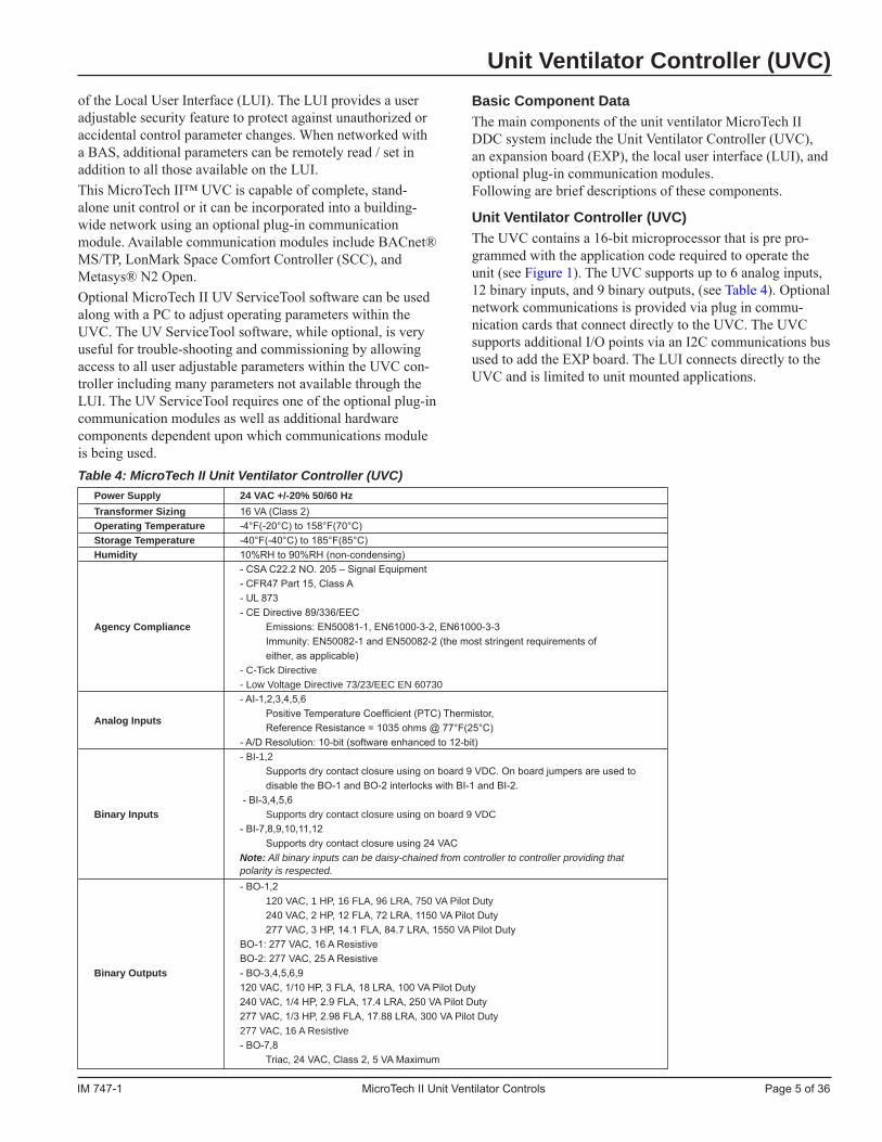
of the Local User Interface (LUI). The LUI provides a user adjustable security feature to protect against unauthorized or accidental control parameter changes. When networked with a BAS, additional parameters can be remotely read / set in addition to all those available on the LUI. This MicroTech II™ UVC is capable of complete, stand-alone unit control or it can be incorporated into a building-wide network using an optional plug-in communication module. Available communication modules include BACnet® MS/TP, LonMark Space Comfort Controller (SCC), and Metasys® N2 Open. Optional MicroTech II UV ServiceTool software can be used along with a PC to adjust operating parameters within the UVC. The UV ServiceTool software, while optional, is very useful for trouble-shooting and commissioning by allowing access to all user adjustable parameters within the UVC con-troller including many parameters not available through the LUI. The UV ServiceTool requires one of the optional plug-in communication modules as well as additional hardware components dependent upon which communications module is being used.Table 4: MicroTech II Unit Ventilator Controller (UVC)
Unit Ventilator Controller (UVC)Basic Component DataThe main components of the unit ventilator MicroTech II DDC system include the Unit Ventilator Controller (UVC), an expansion board (EXP), the local user interface (LUI), and optional plug-in communication modules. Following are brief descriptions of these components.
Unit Ventilator Controller (UVC)The UVC contains a 16-bit microprocessor that is pre pro-grammed with the application code required to operate the unit (see Figure 1). The UVC supports up to 6 analog inputs, 12 binary inputs, and 9 binary outputs, (see Table 4). Optional network communications is provided via plug in commu-nication cards that connect directly to the UVC. The UVC supports additional I/O points via an I2C communications bus used to add the EXP board. The LUI connects directly to the UVC and is limited to unit mounted applications.
Power Supply 24 VAC +/-20% 50/60 Hz Transformer Sizing 16 VA (Class 2) Operating Temperature -4°F(-20°C) to 158°F(70°C) Storage Temperature -40°F(-40°C) to 185°F(85°C) Humidity 10%RH to 90%RH (non-condensing) - CSA C22.2 NO. 205 – Signal Equipment - CFR47 Part 15, Class A - UL 873 - CE Directive 89/336/EEC Agency Compliance Emissions: EN50081-1, EN61000-3-2, EN61000-3-3 Immunity: EN50082-1 and EN50082-2 (the most stringent requirements of either, as applicable) - C-Tick Directive - Low Voltage Directive 73/23/EEC EN 60730 - AI-1,2,3,4,5,6
Analog Inputs Positive Temperature Coefficient (PTC) Thermistor,
Reference Resistance = 1035 ohms @ 77°F(25°C) - A/D Resolution: 10-bit (software enhanced to 12-bit) - BI-1,2 Supports dry contact closure using on board 9 VDC. On board jumpers are used to disable the BO-1 and BO-2 interlocks with BI-1 and BI-2. - BI-3,4,5,6 Binary Inputs Supports dry contact closure using on board 9 VDC - BI-7,8,9,10,11,12 Supports dry contact closure using 24 VAC Note: All binary inputs can be daisy-chained from controller to controller providing that polarity is respected. - BO-1,2 120 VAC, 1 HP, 16 FLA, 96 LRA, 750 VA Pilot Duty 240 VAC, 2 HP, 12 FLA, 72 LRA, 1150 VA Pilot Duty 277 VAC, 3 HP, 14.1 FLA, 84.7 LRA, 1550 VA Pilot Duty BO-1: 277 VAC, 16 A Resistive BO-2: 277 VAC, 25 A Resistive Binary Outputs - BO-3,4,5,6,9 120 VAC, 1/10 HP, 3 FLA, 18 LRA, 100 VA Pilot Duty 240 VAC, 1/4 HP, 2.9 FLA, 17.4 LRA, 250 VA Pilot Duty 277 VAC, 1/3 HP, 2.98 FLA, 17.88 LRA, 300 VA Pilot Duty 277 VAC, 16 A Resistive - BO-7,8 Triac, 24 VAC, Class 2, 5 VA Maximum

Page 6 of 36 MicroTech II Unit Ventilator Controls IM 747-1
Figure 1: MicroTech II Unit Ventilator Controller (UVC)
Expansion Board (EXP)The EXP board provides additional I/O points required by the UVC for unit ventilator operation (see Figure 2). The EXP is operated and monitored by the UVC through the use of an I2C bus.The EXP I/O board supports up to 4 analog inputs and 8 binary outputs (see Table 5).Figure 2: Expansion Board (EXP)
Unit Ventilator Controller (UVC)
Table 5: Expansion Board (EXP) Specifications
Operating Temperature Storage Temperature
Same as UVC Humidity Agency Compliance
- xAI-1,2 Ratiometric 0.5 to 4.5 VDC - xAI-3 0 to 10 VDC Analog Inputs - xAI-4 Positive Temperature Coefficient (PTC) Thermistor, Reference Resistance = 1035 ohms @ 77OF(25OC) - A/D Resolution: 10-bit (software enhanced to 12-bit) - xBO-1,2 120 VAC, 1/10 HP, 3 FLA, 18 LRA, 100 VA Pilot Duty 240 VAC, 1/4 HP, 2.9 FLA, 17.4 LRA, 250 VA Pilot Duty 277 VAC, 1/3 HP, 2.98 FLA, 17.88 LRA, 300 VA Pilot Duty 277 VAC, 16 A Resistive - xBO-3,4,5,6 Binary Outputs Triac, 24 VAC, Class 2, 5 VA Maximum - xBO-7,8 120 VAC, 1 HP, 16 FLA, 96 LRA, 750 VA Pilot Duty 240 VAC, 2 HP, 12 FLA, 72 LRA, 1150 VA Pilot Duty 277 VAC, 3 HP, 14.1 FLA, 84.7 LRA, 1550 VA Pilot Duty xBO-1: 277 VAC, 16 A Resistive xBO-2: 277 VAC, 25 A Resistive

IM 747-1 MicroTech II Unit Ventilator Controls Page 7 of 36
Local User Interface (LUI)The LUI provides the user a local unit mounted interface which indicates the current unit operating state and can be used to adjust many unit ventilator operating parameters. The LUI features a 2-digit display, 7 keys (1 key is hidden), and 9 individual LED indicators.Figure 3: Local User Interface (LUI)
Plug-in LonMark Space Comfort Controller (SCC) Communication Module (Optional)The LonMark SCC communication module is designed to be an add-on module to the UVC for networking to Building Automation Systems using LonWorks® network communi-cations. It supports the LonMark Space Comfort Controller (SCC) profile number 8500. It is an optional plug-in module that can be attached to the UVC via a 12-pin header and 4 locking standoffs to securely attach it to the UVC.Figure 4: LonWorks SCC Communication Module (4" x 2") PN 107293127
Figure 5: Communication Module Location - Behind Right Front Access Panel on AH Unit Types, or Below the Top Right Access Door on AV, AZ, AE, AR, ER and GR Unit Types
Plug-in BACnet® MS/TP Communication Module (Optional)The BACnet MS/TP communication module is designed to be an add-on module to the UVC for networking to Building Automation and Control Network (BACnet) systems. It is an optional plug-in module that can be attached to the UVC via a 12-pin header and 4 locking standoffs to securely attach it to the UVC (see Figure 6). It allows the UVC to inter-operate with systems that use the BACnet Master Slave / Token Pass-ing (MS/TP) protocol with a conformance level of 3. It meets the requirements of ANSI/AHSRAE 135-1995 standard for BACnet systems.Figure 6: BACnet MS/TP Communication Module (4" x 2") PN-107293126
Plug-In Communication Modules
Communication Module Location

Page 8 of 36 MicroTech II Unit Ventilator Controls IM 747-1
Plug-in Metasys® N2 Open Communication Module (Optional)The Metasys N2 Open communication module is designed to be an add-on module to the UVC for networking to a Build-ing Automation System of the Metasys N2 type. It provides N2 Open network communication capability to the UVC. It is an optional plug-in module that can be attached to the UVC via a 12-pin header and 4 locking standoffs to securely attach it to the UVC (Figure 7).Figure 7: Metasys N2 Open Communication Module (4" x 2") PN-107293125
Master-Slave Communication Modules (Optional)On master-slave unit ventilators a communication module is designed to be an add-on module to the UVC for peer-to-peer communications. It is an optional plug-in module that can be attached to the UVC via a 12-pin header and 4 locking standoffs to securely attach it to the UVC. It allows the UVC to inter-operate with another unit setup for master slave com-munication capability.
NOTICE Do not use master/slave units when a BAS will be connected to
the UVC.
Table 6: Master / Slave Network Variable Binding List
Plug-In Communication Modules
NOTICE Master/slave units will not be able to be connected with other
LonWorks devices without re-performing the network variable binding process in the field.
Master / Slave Control (Optional)When it is desirable to have multiple units within one space (i.e. conference rooms, library, stairwells, cafeteria, etc.), and there is no BAS present, it may be necessary to use one mas-ter unit connected to one or more slave units to ensure each unit within the space operates in a like manner. Each unit provided as a master or slave unit will be factory provided with one master or slave module. The factory will pre-bind network variables from the master and slave unit to provide the master / slave relationship. This binding process will in effect “marry” the master unit with its corresponding slave units for the life of the communication modules. The UVC has been provided with a configuration variable to select if slave units will operate as Independent (default) or Dependent slaves (see Table 6). Refer to Unit Ventilator Unit Control-ler LonWorks Communications Module IM 729 for wiring master/slave units.
NOTICE For proper master/slave operation, it is very important that the
factory correctly understand which units will be master, which units will be slaves, and which slaves will be connected to which master units at the job site. It is the responsibility of the pur-chaser when placing orders to ensure that the factory under-stands these things. It is strongly recommended that each group of master/slave units be purchased separately from stand-alone units, or other master/slave unit groups, to help ensure proper configuration.
NOTICE When using master/slave control, you cannot use the Cycle Fan
feature. Refer to the appropriate software model-specific opera-tion manual for more information on the Fan Cycle feature.
Master Variables Slave Variables Used With... Space Temp Space Temp Independent Slave Setpoint Output Setpoint Input Effective Occupancy Occupancy Sensor
Independent Slave
Fan Speed Output
Fan Speed Independent Slave Command Input and Dependent Slave Space Humidity Output Space Humidity Input Independent Slave Outdoor Air Humidity Output Outdoor Air Humidity Input Independent Slave Space CO2 Output Space CO2 Input Independent Slave Primary Heat Output Primary Heat Input Dependent Slave Secondary Heat Output Secondary Heat Input Dependent Slave Primary Cool Output Primary Cool Input Dependent Slave Secondary Cool Output Secondary Cool Input Dependent Slave

IM 747-1 MicroTech II Unit Ventilator Controls Page 9 of 36
Temperature SensorThe UVC is configured to use passive Positive Temperature Coefficient (PTC) unit-mounted and wall-mounted sensors (see Figure 8 and Figure 37, 38 & 39). These sensors vary their input resistance to the UVC as the sensed temperature changes (see Table 7). See Figure 9 for sensor locations.Figure 8: Unit Mounted Sensor, for Outdoor Air, Discharge Air and Room Air
Table 7: Temperature Sensor Specifications
Type Passive Positive Temperature Coefficient (PTC) - Silicon Sensing Element Range -40°F(-40°C) to 212°F(100°C) Reference Resistance 1035 ohms at 77°C(25°C) Accuracy 0.9°F(0.5°C) between 5°F(-15°C) to 167°F(75°C) Leads 22 AWG, 2-wire (white)
Figure 9: Sensor Locations
Humidity Sensor (Optional)On units equipped with humidity sensors, the UVC is con-figured to use a 0-100% RH, 0-5 VDC, capacitive humidity sensor(s) (see Figure 10 and Table 8). Humidity sensors are available as unit mounted only. The humidity sensors are used with units capable of passive or active dehumidification, or with units using outdoor enthalpy economizer or indoor/ outdoor enthalpy economizer.
Figure 10: Humidity Sensor
Table 8: Humidity Sensor Specifications Type Capacitive Humidity Sensor Voltage Supply 5 VDC Nominal (4.75 VDC to 5.25 VDC) Voltage Output 1 to 4 VDC output for 0 to 100 %RH at 5 VDC supply (ratiometric to voltage supply) (70 ohm output impedence) Operating Temp -22°F(-30°C) to 140°F(60°C) Storage Temp -40°F(-30°C) to 158°F(70°C) Humidity 0%RH to 100%RH (not affected by water immersion) Sensing Range 1 to 99 %RH Accuracy +/- 3 %RH Typical, +/- 5 %RH Maximum Calibration Calibrated to within +/- 2 %RH at 55 %RH Leads 24 AWG, 3-wire (blue-supply, yellow-output, white-ground)
! CAUTION The humidity sensor is not protected against reversed polar-
ity. Check carefully when servicing the device or equipment damage will result.
Sensors
Discharge Air Sensor
Room Air Sensor
Holes in Front Access Panel
Outdoor Air Sensor
Outdoor Air Opening

Page 10 of 36 MicroTech II Unit Ventilator Controls IM 747-1
Carbon Dioxide (CO2) Sensor (Optional) for Demand Controlled Ventilation (DCV)On units equipped for Demand Controlled Ventilation (CO2 sensor installed), the UVC is configured to use a 0-2000 PPM, 0-10 VDC, single beam absorption infrared gas sensor (see Figure 11 and Table 9). The CO2 sensor is used by the UVC’s CO2 Demand Controlled Ventilation feature. CO2 sensors are available as unit mounted only. An air collection probe (pitot tube and filter) is installed in the return air of the unit (see Figure 12).Figure 11: Carbon Dioxide (CO2) Sensor
Figure 12: Air Collecting Probe
Table 9: Carbon Dioxide (CO2) Sensor Specifications Type Single Beam Absorption Infrared Gas Sensor Operating Temp 60°F(15°C) to 90°F(32°C) Storage Temp -40°F(-40°C) to 158°F(70°C) Humidity 0%RH to 95%RH (non-condensing) Power Supply 18 to 30 VAC 50/60 Hz Transformer Sizing 1.75 VA (Class 2) Sensing Range 0 to 2000 PPM Voltage Output 0 to 10 VDC (100 ohm output impedance) Accuracy +/- 100 PPM or 7% of range whichever is greater
Calibration Self-calibration system eliminates the need for
manual calibration in most applications
Actuators
Pitot Tube
Filter
Face & Bypass Damper Actuator (Optional)On units equipped with a face & bypass damper, the UVC is configured to operate a floating-point (tri-state) face & bypass damper, direct coupled actuator (see Figure 13 and Table 10).To determine the modulating damper position the UVC uses a separate factory preset, configurable setting for each actuator's stroke time. To ensure the accuracy of actuator positioning the UVC is provided with an overdrive feature for the 0% and 100% positions and also periodic (12-hour) autozero algo-rithm for each modulating actuator.Figure 13: Face & Bypass Damper Actuator
Outdoor Air/Return Air Damper (OAD) ActuatorThe UVC is configured to operate a floating-point (tri-state) Outdoor Air Damper direct coupled, spring returned shut actuator (see Figure 14 and Table 11). The OAD actuator provides spring return operation upon loss of power positive close-off of the outdoor air damper.To determine damper position the UVC uses a separate fac-tory preset, configurable setting for each actuator's stroke time. To ensure the accuracy of actuator positioning the UVC is provided with an overdrive feature for the 0% and 100% positions and also a periodic (12- hour) auto-zero algorithm for each modulating actuator.Figure 14: Outdoor Air/Return Air Damper Actuator

IM 747-1 MicroTech II Unit Ventilator Controls Page 11 of 36
Table 11: Outdoor Air/Return Air Damper (OAD) Actuator Specifications
Type Floating Point (tri-state), Spring Return, Direct
Coupled Actuator Power Supply 24 VAC +/- 20% 50/60 Hz Power Consumption 2.5 W Running, 1 W Holding Transformer Sizing 5 VA (Class 2) Operating Temp -22°F(-30°C) to 122°F(50°C) Storage Temp -40°F(-40°C) to 176°F(80°C) Humidity 5%RH to 95%RH (non-condensing) Torque 35 in-lb (4 Nm) Run Time 90-second constant, independent of load Overload Protection Electronic throughout rotation
Noise Level Less than 30 dB(A) Running, less than 62 dB(A)
Spring Return
Direction of Rotation Spring: Reversible with cw/ccw mounting
Motor: Reversible with built-in switch
Position Indication Visual Indicator, 0° to 90° (0° is the spring return
position)
Leads 18 AWG, 4-wire (red-24 VAC supply, black-24
VAC common, white-ccw, green-cw)
2-Position End-of-Cycle (EOC) Valves (Optional)On units equipped with 2-way or 3-way end of- cycle (EOC) valves, the UVC is configured to operate 2-position End-Of-Cycle (EOC) valve actuators (see Figure 16 and Table 12).Spring return actuators are used for all End of Cycle (EOC) valves. All wet heat and heat/cool EOC valves are normally open, and all cooling EOC valves are normally closed.Figure 16: 2-Position End of Cycle Valve Actuator (EOC)
Table 12: 2-Position End of Cycle (EOC) Valve Actuator Specifications Type 2-position, Spring Return, Electric Valve Actuator Power Supply 24 VAC 50/60 Hz Power Consumption 6.5 W Running Transformer Sizing 7 VA (class 2) Dependent upon valve ordered: Fluid Limits at General: 32°F(0°C) to 200°F(93°C) at 104°F(40°C) Ambient Temp Limit Steam: 32°F(0°C) to 250°F(121°C) at 169°F(76°C), 15 psig (103 kPa) Run Time 9 to 11-seconds Spring Return 4 to 5-seconds
Figure 15: Damper Actuators Located in Left End Compartment
For correct space control, and proper unit operation, use End-of-Cycle (EOC) valves in all face & bypass damper equipped unit ventilators. An EOC valve is required for the wet heat coil in any unit ventilator that combines both a refrigerant coil and a wet heat coil. Use an EOC valve on all wet heat coils to minimize the potential for overheating.
Table 10: Face & Bypass Damper Actuator Specifications Type Floating Point (tri-state), Direct Coupled Actuator Power Supply 24 VAC +/- 20% 50/60 Hz Power Consumption 2 W Running Transformer Sizing 3 VA (Class 2) Operating Temp -22°F(-30°C) to 122°F(50°C) Storage Temp -40°F(-40°C) to 176°F(80°C) Humidity 5%RH to 95%RH (non-condensing) Torque 35 in-lb (4 Nm) Run Time 80 to 110-second for 0 to 35 in-lb Overload Protection Electronic throughout rotation Manual Override External push button Noise Level Less than 35 dB(A) Running Direction of Rotation Reversible with built-in switch Position Indication Clip-on Indicator Leads 18 AWG, 3-wire (black-24 VAC common, red-ccw, white-cw)
Valves
! CAUTION

Page 12 of 36 MicroTech II Unit Ventilator Controls IM 747-1
Figure 19: 3-Way Modulating Valve Actuator
Table 14: Modulating Valve Actuator Specifications
Type Floating Point (tri-state), Spring Return, Electric
Valve Actuator Power Supply 20 to 30 VAC 50/60 Hz Transformer Sizing 12 VA (class 2) Operating Temp 32°F(0°C) to 122°F(50°C) Storage Temp -85°F(-65°C) to 185°F(85°C)
Humidity 90 % RH non-condensing at 70°F(21°C) ambient
temperature and 40°F(4°C) fluid temperature
Fluid Temp Limits 35°F(2°C) to 250°F(121°C); 15 psig (103 kPa)
saturated steam Force Output Minimum 61 lb (271 N) Maximum Stroke 29/32 in. (23 mm) Run Time 76-seconds (proportionally less for shorter stroke) Spring Direction Stem-up, 3 to 15-seconds spring return Noise Level 35 dB(A)
Leads 20 AWG, 4-wire (yellow-24 VAC supply, white-24
VAC common, white/brown-stem up, brown-stem down)
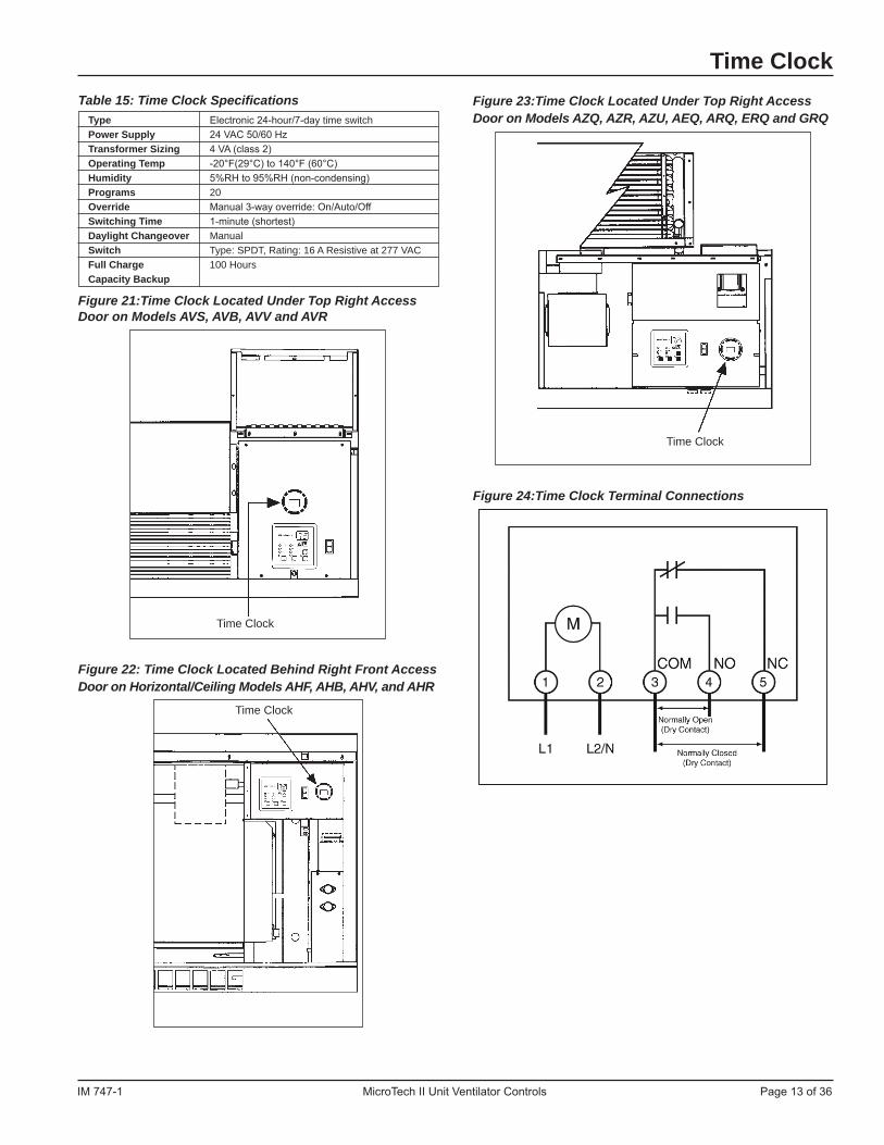
Time Clock with Stand-Alone Unit Ventilators (Optional)As an option, stand-alone, non-servant unit ventilators are factory-equipped with a unit-mounted, digital, 24-hour/7-day time clock with 20 programs.The clock is factory-wired to automatically place the unit into occupied or unoccupied mode based upon its schedule. Features of this clock include:• Large keys with circular programming for easy schedule
setup• An LCD display• Manual 3-way override (On/Auto/Off)• Capacitor backup to retain program memory during power
outages. (See OM 1101) for operating and setting the time clock.)
Figure 20: Time Clock
WSHP 2-Position Motorized Water Valves (Optional)On water source heat pump unit ventilators equipped with a motorized water valve, the UVC is configured to operate a 2-position motorized water valve actuator (see Figure 17 and Table 13). Spring return actuators are used for all motorized water valves. All motorized water valves are normally closed.Figure 17: WSHP 2-Position Motorized Water Valve
Table 13: WSHP 2-Position Motorized Valve Actuator Specifications Type 2-position, Spring Return, Electric Valve Actuator Power Supply 24 VAC 50/60 Hz Power Consumption 6.5 W Running Transformer Sizing 7 VA (class 2) Fluid Limits at 32°F(0°C) to 200°F(93°C) at 104°F(40°C) Ambient Temp Limit Run Time 9 to 11-seconds Spring Return 4 to 5-seconds
Modulating Valve Actuators (Optional)On units equipped with modulating valves, the UVC is con-figured to operate floating point (tri-state) actuators for modu-lating 2- way and 3-way valves (see Figure 18 and Figure 19, and Table 14).Spring return actuators are used for all Modulating valves. All wet heat and heat/ cool valves are normally open, all cooling valves are normally closed.To determine modulating valve position the UVC uses a sepa-rate factory preset, configurable setting for each actuator's stroke time. To ensure the accuracy of actuator positioning the UVC is provided with an overdrive feature for the 0% and 100% positions and also periodic (12-hour) autozero algo-rithm for each modulating actuator.Figure 18: 2-Way Modulating Valve Actuator
Valves
IM 747-1 MicroTech II Unit Ventilator Controls Page 13 of 36
Table 15: Time Clock Specifications Type Electronic 24-hour/7-day time switch Power Supply 24 VAC 50/60 Hz Transformer Sizing 4 VA (class 2) Operating Temp -20°F(29°C) to 140°F (60°C) Humidity 5%RH to 95%RH (non-condensing) Programs 20 Override Manual 3-way override: On/Auto/Off Switching Time 1-minute (shortest) Daylight Changeover Manual Switch Type: SPDT, Rating: 16 A Resistive at 277 VAC Full Charge 100 Hours Capacity Backup
Figure 21:Time Clock Located Under Top Right Access Door on Models AVS, AVB, AVV and AVR
Figure 22: Time Clock Located Behind Right Front Access Door on Horizontal/Ceiling Models AHF, AHB, AHV, and AHR
Time ClockFigure 23:Time Clock Located Under Top Right Access Door on Models AZQ, AZR, AZU, AEQ, ARQ, ERQ and GRQ
Figure 24:Time Clock Terminal Connections
Time Clock
Time Clock
Time Clock

Page 14 of 36 MicroTech II Unit Ventilator Controls IM 747-1
Make Electrical Wiring Connections
! WARNING To avoid electrical shock, personal injury or death, be sure that
field wiring complies with local and national fire, safety, and elec-trical codes, and voltage to the system is within the limits shown in the job-specific drawings and unit electrical data plate(s).
! DANGER Power supply to unit must be disconnected when making field-
connections. To avoid electrical shock, personal injury or death, be sure to rigorously adhere to field wiring procedures regarding proper lockout and tagout of components.
! CAUTION Use copper conductors only. Use of aluminum conductors may
result in equipment failure and overheating hazards. All wiring in right hand compartment must be class 1.
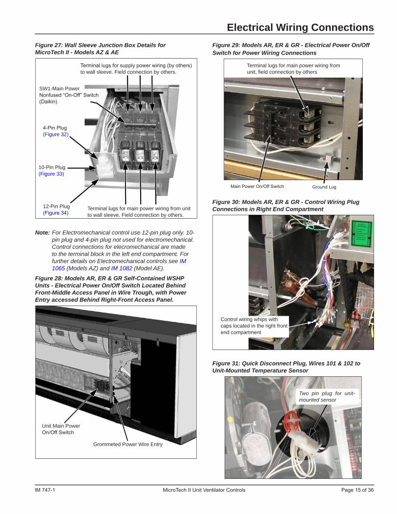
Field Wiring Harness LocationsThe low voltage field wiring connections have all been cen-trally located within the unit ventilator and are easily acces-sible.To simplify field connections, multi-pin plugs are factory pro-vided and pre-wired with short wire whips. Each of the wires in these wire whips is capped and should remain capped if not used. To make a field connection simply locate the correct wire, cut the wire cap from the wire and then connect the wire
Electrical Wiring Connectionswith your field wiring as shown in the field wiring diagrams.The unit mounted temperature sensor is provided with a quick disconnect plug (white) with wires numbered 101 and 102, and must be separated so that the unit mounted sensor is disconnected from the UVC. This disables the unit mounted sensor (see Figure 31).All low voltage field wiring connections must be run in shielded cable with the shield drain wires connected as shown in the field wiring diagrams.See the wiring diagram provided on the unit ventilator right front access panel.In addition, those unit ventilators equipped with optional elec-tric heating coil have electric heating coil power connections at right end only.Figure 25: Model AV - Field Wiring Whips with Caps Viewed from Right End Compartment
Figure 26: Wiring Location Using Wall Sleeve with Models AZQ, AZR, AZU and AEQ
Field Wiring at back of Local User Interface (LUI) Panel
Wire Wips for Field Wiring with Caps (see the wiring diagram provided on the unit ventilator right front access panel)
Two pin plug for unit mounted sensor
Control receptacle with plug-in disconnect (Daikin®). Leads are provided for wire nut connection to all remote controls.
5/8" x 3-5/8" opening (for main power wiring from wall sleeve to chassis). Field connection by others.
Wall Sleeve Junction Box
SW1-Main Power Non-Fused “On-Off” Switch (Daikin)
.875" Diameter Knockouts (3)2.5" / 1.75" Diameter Knockout3.0" / 2.0" Diameter Knockout
Wall Sleeve
Rear Edge of Wall Sleeve
NOTICE: Reverse this cover when unit is removed from wall sleeve to cover opening in the end of switch box.
IM 747-1 MicroTech II Unit Ventilator Controls Page 15 of 36
Figure 29: Models AR, ER & GR - Electrical Power On/Off Switch for Power Wiring Connections
Figure 30: Models AR, ER & GR - Control Wiring Plug Connections in Right End Compartment
Figure 31: Quick Disconnect Plug, Wires 101 & 102 to Unit-Mounted Temperature Sensor
Electrical Wiring ConnectionsFigure 27: Wall Sleeve Junction Box Details for MicroTech II - Models AZ & AE
Note: For Electromechanical control use 12-pin plug only. 10-pin plug and 4-pin plug not used for electromechanical. Control connections for elecromechanical are made to the terminal block in the left end compartment. For further details on Electromechanical controls see IM 1065 (Models AZ) and IM 1082 (Model AE).
Figure 28: Models AR, ER & GR Self-Contained WSHP Units - Electrical Power On/Off Switch Located Behind Front-Middle Access Panel in Wire Trough, with Power Entry accessed Behind Right-Front Access Panel.
Terminal lugs for main power wiring from unit, field connection by others
Main Power On/Off Switch Ground Lug
Control wiring whips with caps located in the right front end compartment
Grommeted Power Wire Entry
Unit Main Power On/Off Switch
Two pin plug for unit-mounted sensor
Terminal lugs for main power wiring from unit to wall sleeve. Field connection by others.
SW1-Main Power Nonfused “On-Off” Switch (Daikin)
Terminal lugs for supply power wiring (by others) to wall sleeve. Field connection by others.
4-Pin Plug (Figure 32)
10-Pin Plug (Figure 33)
12-Pin Plug (Figure 34)

Page 16 of 36 MicroTech II Unit Ventilator Controls IM 747-1
Electrical Wiring ConnectionsFigure 32: 4-pin Plug MicroTech II Control Wiring Diagram
CommunicationModule
(4-pin)Male ConnectorUnit Ventilator
Optional Building Automation System (BAS)
Note:The N2 Bus can use either solid or stranded wires of the following types:3-wire twisted cable, 2 twisted-pair telephone cable, or two twisted pair with shield. The wiring is polarity sensitive.The polarity of the signal must always be maintained throughout the network. Always connect + to + and - to -. The shield connection must be continuous throughout the entire network and must be connected to earth ground at one (and only one) point.
Use Belden 8471, NEMA Level 4, or Echelon-approved equivalent wire.Since the LONWORKS communication wiring is polarity insensitive, no polarity must be observed when making connections via the unshielded twisted-pair wiring.
Wiring: Use twisted shielded pair (Connect Air W221P-2544 or equivalent).Daisy-chain and tie shield to earth ground at one point only.The polarity of the signal must always be maintained throughout the network.Always connect + to + and - to -. The shield connection must be continuous throughout the entire network and must be connected to earth ground at one (and only one) point.
LONWORKS®
FTT–10 (A)
FTT–10 (B)
BACnet ® Metasys®
GND
32
1
(4-pin)Female Connector
Black
Red
GNDN2–
N2+
GNDRT-
RT+
(By others)(By others)(By others)
Figure 33: 10-pin Plug MicroTech II™ Wiring Diagram
Shield
P6 (10-pin) Connector
Unit Ventilator
xBO-2
xBO-1BO-6BO-6
P6 (10-pin) Connector
WireCaps
601A602A603A604A605A
External OutputOption 1 Device
(by others)
External OutputOption 2 Device
(by others)
External OutputOption 3 Device
(by others)
Lights On/OfffSignal or
Motorized WaterValve Open/Close
Fault Indicationor
Pump RestartSignal
Auxiliary HeatSignal
orExhaust FanOn/Off Signal
Comm
Comm
606A608A610A
24vac Supply24vac Comm
601602603604605606608610
Figure 34: 12-pin Plug MicroTech II™ Control Wiring Diagram
GNDComm
BI-6BI-5BI-4
896908A907A906A905A
Shield896908907906905
P1 (12-pin)Connector
Unit VentilatorP1 (12-pin)Connector
6432
51
Setpnt Adjst.CommSensorLED
GNDAI-2
CommAI-1LED
WireCaps
896GRNBLKWHTRED
896GRNBLKWHTRED
Remote Wall Sensor(Option)
External InputOption 3 Device
(by others)
External InputOption 2 Device
(by others)
External InputOption 1 Device
(by others)
Ventilation Lockout(default) or
Exhaust Interlock
RemoteShutdown
Unoccupied (default)or Dewpoint Humidity
Shield
Note: Not all external input options are available for all models.
Note: Not all external input options are available for all models.

IM 747-1 MicroTech II Unit Ventilator Controls Page 17 of 36
Electrical Wiring ConnectionsElectroMechanical Unit Type (Optional for AR, ER & GR) - Wiring Connection LocationElectromechanical control connections are made to the ter-minals located behind the left-front access panel as shown in Figure 35. Refer to the wiring diagram (Figure 36) for wiring details and the wiring diagram provided with the unit.Figure 35: Thermostat Control Terminal Connections Located in Left Front Compartment - Electomechanical
Figure 36: Typical ElectroMechanical Wiring Diagram - Model AR, Thermostat Control with Normally Open Heat, 460 Volt - 3Phase
Terminal Connections for Electromechanical Controls
Page 18 of 36 MicroTech II Unit Ventilator Controls IM 747-1
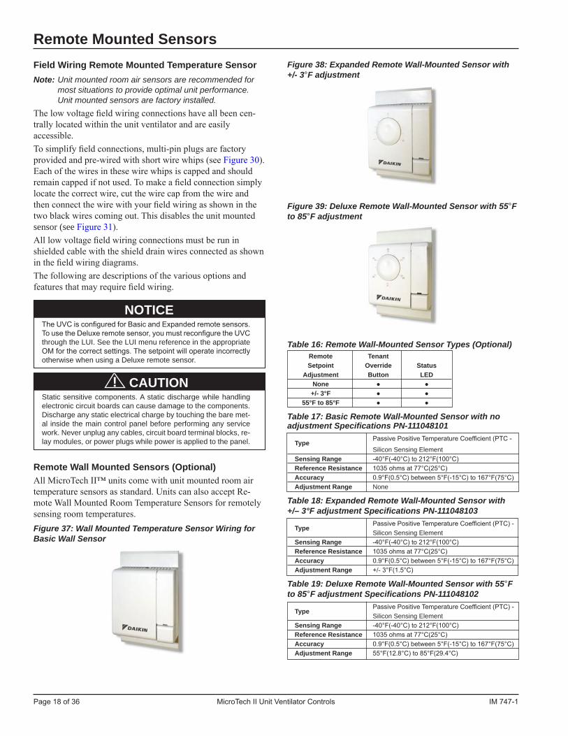
Figure 38: Expanded Remote Wall-Mounted Sensor with +/- 3°F adjustment
Figure 39: Deluxe Remote Wall-Mounted Sensor with 55°F to 85°F adjustment
Table 16: Remote Wall-Mounted Sensor Types (Optional) Remote Tenant Setpoint Override Status Adjustment Button LED None ● ● +/- 3°F ● ● 55°F to 85°F ● ●
Table 17: Basic Remote Wall-Mounted Sensor with no adjustment Specifications PN-111048101
Type Passive Positive Temperature Coefficient (PTC -
Silicon Sensing Element Sensing Range -40°F(-40°C) to 212°F(100°C) Reference Resistance 1035 ohms at 77°C(25°C) Accuracy 0.9°F(0.5°C) between 5°F(-15°C) to 167°F(75°C) Adjustment Range None
Table 18: Expanded Remote Wall-Mounted Sensor with +/– 3°F adjustment Specifications PN-111048103
Type Passive Positive Temperature Coefficient (PTC) -
Silicon Sensing Element Sensing Range -40°F(-40°C) to 212°F(100°C) Reference Resistance 1035 ohms at 77°C(25°C) Accuracy 0.9°F(0.5°C) between 5°F(-15°C) to 167°F(75°C) Adjustment Range +/- 3°F(1.5°C)
Table 19: Deluxe Remote Wall-Mounted Sensor with 55°F to 85°F adjustment Specifications PN-111048102
Type Passive Positive Temperature Coefficient (PTC) -
Silicon Sensing Element Sensing Range -40°F(-40°C) to 212°F(100°C) Reference Resistance 1035 ohms at 77°C(25°C) Accuracy 0.9°F(0.5°C) between 5°F(-15°C) to 167°F(75°C) Adjustment Range 55°F(12.8°C) to 85°F(29.4°C)
Field Wiring Remote Mounted Temperature SensorNote: Unit mounted room air sensors are recommended for
most situations to provide optimal unit performance. Unit mounted sensors are factory installed.
The low voltage field wiring connections have all been cen-trally located within the unit ventilator and are easily accessible.To simplify field connections, multi-pin plugs are factory provided and pre-wired with short wire whips (see Figure 30). Each of the wires in these wire whips is capped and should remain capped if not used. To make a field connection simply locate the correct wire, cut the wire cap from the wire and then connect the wire with your field wiring as shown in the two black wires coming out. This disables the unit mounted sensor (see Figure 31).All low voltage field wiring connections must be run in shielded cable with the shield drain wires connected as shown in the field wiring diagrams.The following are descriptions of the various options and features that may require field wiring.
NOTICE The UVC is configured for Basic and Expanded remote sensors.
To use the Deluxe remote sensor, you must reconfigure the UVC through the LUI. See the LUI menu reference in the appropriate OM for the correct settings. The setpoint will operate incorrectly otherwise when using a Deluxe remote sensor.
! CAUTION Static sensitive components. A static discharge while handling
electronic circuit boards can cause damage to the components. Discharge any static electrical charge by touching the bare met-
al inside the main control panel before performing any service work. Never unplug any cables, circuit board terminal blocks, re-lay modules, or power plugs while power is applied to the panel.
Remote Wall Mounted Sensors (Optional)All MicroTech II™ units come with unit mounted room air temperature sensors as standard. Units can also accept Re-mote Wall Mounted Room Temperature Sensors for remotely sensing room temperatures. Figure 37: Wall Mounted Temperature Sensor Wiring for Basic Wall Sensor
Remote Mounted Sensors
IM 747-1 MicroTech II Unit Ventilator Controls Page 19 of 36
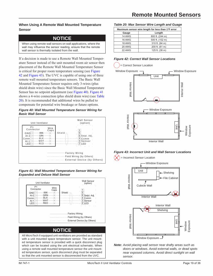
When Using A Remote Wall Mounted Temperature Sensor
NOTICE When using remote wall sensors on wall applications, where the
wall may influence the sensor reading, ensure that the remote wall sensor is thermally isolated from the wall.
If a decision is made to use a Remote Wall Mounted Temper-ature Sensor instead of the unit mounted room air sensor then placement of the Remote Wall Mounted Temperature Sensor is critical for proper room temperature sensing (see Figure 42 and Figure 43). The UVC is capable of using one of three remote wall mounted temperature sensors. The Basic Wall Mounted Temperature Sensor requires only 3-wires (plus shield drain wire) since the Basic Wall Mounted Temperature Sensor has no setpoint adjustment (see Figure 40). Figure 41 shows a 4-wire connection (plus shield drain wire) (see Table 20). It is recommended that additional wires be pulled to compensate for potential wire breakage or future options. Figure 40: Wall Mounted Temperature Sensor Wiring for Basic Wall Sensor
896
P 1C o n n e c t o r
BLKWHTR E D
WireC a p s
Unit Ventilator
LED
C o m mAI-1
AI-2GND
6432
51
S e t p t . A d j .C o m mS e n s o rLED
Wal l Sensor(opt ion)
S h i e l d
F ie ld Wir ing (by Others)E x t e r n a l D e v i c e ( b y O t h e r s )
Factory Wir ing
GRN
Figure 41: Wall Mounted Temperature Sensor Wiring for Expanded and Deluxe Wall Sensor
BLK
NOTICE All MicroTech II equipped unit ventilators are provided as standard
with a unit mounted space temperature sensor. The unit mount-ed temperature sensor is provided with a quick disconnect plug which can be located using the unit electrical schematic. When using a remote wall mounted temperature sensor the unit mount-ed temperature sensor, quick disconnect plug must be separated so that the unit mounted sensor is disconnected from the UVC.
Table 20: Max Sensor Wire Length and Guage Maximum sensor wire length for less than 1°F error Gauge Length 14 AWG 800 ft. (244 m) 16 AWG 500 ft. (152 m) 18 AWG 310 ft. (94 m) 20 AWG 200 ft. (61 m) 22 AWG 125 ft. (38 m)
Figure 42: Correct Wall Sensor Locations
Figure 43: Incorrect Unit and Wall Sensor Locations
Note: Avoid placing wall sensor near drafty areas such as doors or windows. Avoid external walls, or dead spots near exposed columns. Avoid direct sunlight on wall sensor.
Remote Mounted Sensors
= Correct Sensor Location
Window Exposure
Inte
rior W
allInterior W
all
Unit
Window Exposure
Win
dow
E
xpos
ure
Interior Wall
Unit
Window Exposure
Cubicle Wall
= Incorrect Sensor Location
Shelving
Shelving
File Cabinet
Interior Wall
Interior Wall
Window Exposure
Unit
Unit
Win
dow
E
xpos
ure
Window Exposure
Interior Wall
Interior Wall
Interior Wall
Page 20 of 36 MicroTech II Unit Ventilator Controls IM 747-1
! DANGER To avoid electrical shock, personal injury or death, be sure that
field wiring complies with local and national fire, safety, and elec-trical codes, and voltage to the system is within the limits shown in the job-specific drawings and unit electrical data plate(s).
Power supply to unit must be disconnected when making field connections. To avoid electrical shock, personal injury or death, be sure to rigorously adhere to field wiring procedures regarding proper lockout and tagout of components.
InstallationThis document describes the installation of the following three wall mounted sensor models:• P/N 111048101• P/N 111048102• P/N 111048103
Parts Included - All Models• pre-assembled sensor that includes: - large (50.8 x 101.6 mm [2 x 4 in.]) mounting base (1) - terminal block (1) - 1.5 mm (1/16 in.) cover screw (1) - endcaps (2)• alternate small (80 x 80 mm [3.15 x 3.15 in.]) mounting
base (1) with attached terminal block (1)• cover slider insert with printed logos for McQuay® (1)
and AAF® (1)• No. 6-32 x 1 in. flat-head screw (2)• No. 8 x 1.25 in. panhead tapping screw (2)• hollow plastic wall anchor (2)
Parts Included - 111048102 and 111048103 Only• alternate serrated setpoint dial (attached)• smooth setpoint dial (separate)
Special Tools Needed• 5 mm (1/16 in.) Allen wrench• 7 mm (1/4 in.) flat-blade screwdriver• hole saw with 35 mm (1-3/8 in.) blade (for surface mounting only)• drill with 8 mm (5/16 in.) drill bit (for surface mounting only)
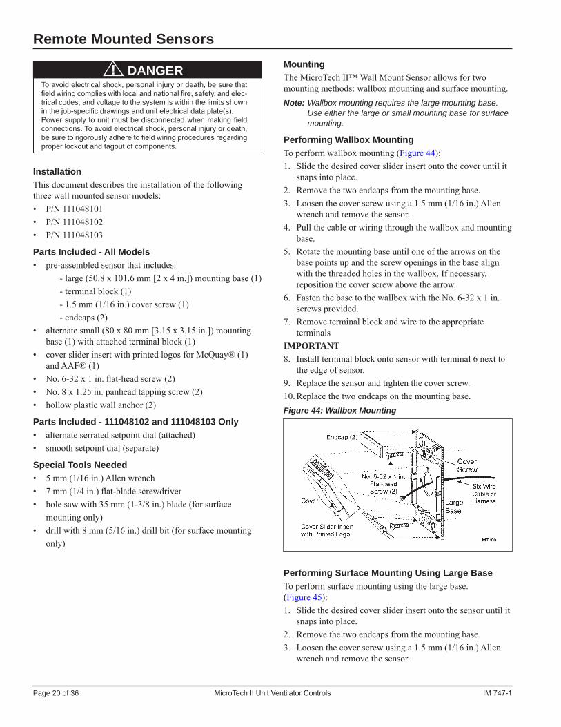
Remote Mounted SensorsMountingThe MicroTech II™ Wall Mount Sensor allows for two mounting methods: wallbox mounting and surface mounting.Note: Wallbox mounting requires the large mounting base.
Use either the large or small mounting base for surface mounting.
Performing Wallbox MountingTo perform wallbox mounting (Figure 44):1. Slide the desired cover slider insert onto the cover until it
snaps into place.2. Remove the two endcaps from the mounting base.3. Loosen the cover screw using a 1.5 mm (1/16 in.) Allen
wrench and remove the sensor.4. Pull the cable or wiring through the wallbox and mounting
base.5. Rotate the mounting base until one of the arrows on the
base points up and the screw openings in the base align with the threaded holes in the wallbox. If necessary, reposition the cover screw above the arrow.
6. Fasten the base to the wallbox with the No. 6-32 x 1 in. screws provided.
7. Remove terminal block and wire to the appropriate terminals
IMPORTANT8. Install terminal block onto sensor with terminal 6 next to
the edge of sensor.9. Replace the sensor and tighten the cover screw.10. Replace the two endcaps on the mounting base.Figure 44: Wallbox Mounting
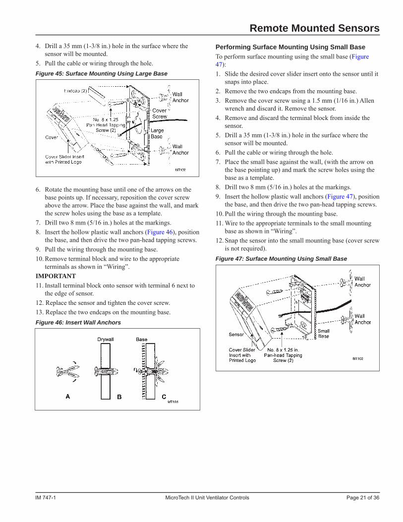
Performing Surface Mounting Using Large BaseTo perform surface mounting using the large base. (Figure 45):1. Slide the desired cover slider insert onto the sensor until it
snaps into place.2. Remove the two endcaps from the mounting base.3. Loosen the cover screw using a 1.5 mm (1/16 in.) Allen
wrench and remove the sensor.
IM 747-1 MicroTech II Unit Ventilator Controls Page 21 of 36
Remote Mounted Sensors4. Drill a 35 mm (1-3/8 in.) hole in the surface where the
sensor will be mounted.5. Pull the cable or wiring through the hole.Figure 45: Surface Mounting Using Large Base
6. Rotate the mounting base until one of the arrows on the base points up. If necessary, reposition the cover screw above the arrow. Place the base against the wall, and mark the screw holes using the base as a template.
7. Drill two 8 mm (5/16 in.) holes at the markings.8. Insert the hollow plastic wall anchors (Figure 46), position
the base, and then drive the two pan-head tapping screws.9. Pull the wiring through the mounting base.10. Remove terminal block and wire to the appropriate
terminals as shown in “Wiring”.IMPORTANT11. Install terminal block onto sensor with terminal 6 next to
the edge of sensor.12. Replace the sensor and tighten the cover screw.13. Replace the two endcaps on the mounting base.Figure 46: Insert Wall Anchors
Performing Surface Mounting Using Small BaseTo perform surface mounting using the small base (Figure 47):1. Slide the desired cover slider insert onto the sensor until it
snaps into place.2. Remove the two endcaps from the mounting base.3. Remove the cover screw using a 1.5 mm (1/16 in.) Allen
wrench and discard it. Remove the sensor.4. Remove and discard the terminal block from inside the
sensor.5. Drill a 35 mm (1-3/8 in.) hole in the surface where the
sensor will be mounted.6. Pull the cable or wiring through the hole.7. Place the small base against the wall, (with the arrow on
the base pointing up) and mark the screw holes using the base as a template.
8. Drill two 8 mm (5/16 in.) holes at the markings.9. Insert the hollow plastic wall anchors (Figure 47), position
the base, and then drive the two pan-head tapping screws.10. Pull the wiring through the mounting base.11. Wire to the appropriate terminals to the small mounting
base as shown in “Wiring”.12. Snap the sensor into the small mounting base (cover screw
is not required).Figure 47: Surface Mounting Using Small Base

Page 22 of 36 MicroTech II Unit Ventilator Controls IM 747-1
Setup and AdjustmentsSwitching Setpoint DialsTo switch setpoint dials:1. Remove the sensor from the mounting base.2. Rotate the smooth setpoint dial so that it points straight up.3. As shown in Figure 50, insert the Allen wrench through
the hole in the back of the printed wiring board (A) and push gently until the smooth setpoint dial is free.
4. Press the serrated setpoint dial into place on the sensor, making sure that the dial points straight up.
5. Replace the sensor on the mounting base.
Repairs and ReplacementNo repair options available. Call your local AAF-McQuayrepresentative for sensor replacement.Figure 50: Removing the Standard Setpoint Dial
External Input Option WiringThe external input options can be one of the following, de-pendent upon the unit ventilator software model: Unoccupied Signal, Remote Shutdown Signal, Ventilation Lockout Signal, Dewpoint/Humidity Signal, Boiler-less System Kit Signal, or Exhaust Interlock Signal.Each of these inputs has been designed such that units can be daisy-chained to one set of dry contacts as shown in Figure 51. Size wiring for minimal voltage drop in accordance with local codes.
! CAUTION Static sensitive components. A static discharge while handling
electronic circuit boards can cause damage to the components. Discharge any static electrical charge by touching the bare met
al inside the main control panel before performing any service work. Never unplug any cables, circuit board terminal blocks, re-lay modules, or power plugs while power is applied to the panel.
Wiring
NOTICE It is suggested that shielded cable always be used, however,
shielded cable is generally not required, except in electrically noisy environments, such as near gas ignition systems, radar or magnetic resonance imaging equipment, etc. It is the respon-sibility of others to determine what constitutes an “electrically noisy” environment for each installation. Refer to Table 21 and Table 21 for maximum wire length.
Figure 48: 111048101 Sensor Wiring
Figure 49: 111048102 and 111048103 Sensor Wiring
Table 21: Maximum Wire Length Maximum Wire Length for Less Than 1°F Error Wire Gauge Wire Length 14 AWG 800 Ft. (244mm) 16 AWG 500 Ft. (152mm) 18 AWG 310 Ft. (94mm) 20 AWG 200 Ft. (61mm) 22 AWG 125 Ft. (38mm)
Remote Mounted Sensors
Setpoint Dial
A

IM 747-1 MicroTech II Unit Ventilator Controls Page 23 of 36
External Output Option WiringThe external output options can be configured as one of the following, dependent upon the unit ventilator software model: Lights On/ Off Signal, Motorized Water Valve Open/Close, Fault Indication Signal, Pump Restart Signal, Exhaust Fan On/Off Signal, and Auxiliary Heat Signal (see Figure 52).Each of these external outputs is connected to the dry contacts of UVC board mounted relays and can be used as a “signal” to operate the 24 VAC coil of a field-installed pilot duty relay as shown. Size wire for minimum voltage drop in accordance with local codes. In the case of the motorized water valve on
Remote Mounted SensorsFigure 51: External Input Wiring Examples with or without Daisy Chaining of Units
water source heat pumps, the appropriate output can be used to operate the valve actuator.The second wiring example (see Figure 53), shows how mu tiple units could be connected to a single relay by others.
NOTICE Not all of the external output options can be used simultane-
ously. Not all of the external output options can be used on all software models. See the “UVC Input and Output Tables” in or-der to verify which external output option can be used on which external outputs for each specific software model.
Figure 52: External Output Wiring – Single Unit
External OutputOption 1 Device
(by Others)
Lights On/OffSignal
orMotorized WaterValve Open/Close
External OutputOption 2 Device
(by Others)
Fault Indicationor
Pump RestartSignal
External OutputOption 3 Device
(by Others)
Auxiliary HeatSignal
orExhaust FanOn/Off Signal
Shield
Factory WiringField Wiring (by Others)External Device (by Others)
Unit Ventilator
UVC601A602A603A604A605A606A608A610A
xBO-2CommxBO-1BO-6BO-6
Comm24vac Supply24vac Comm
P6Connector
WireCaps

Page 24 of 36 MicroTech II Unit Ventilator Controls IM 747-1
NOTICE Not all of the external input options can be used simultaneously.
Not all of the external input options can be used on all software models. See the “UVC Input and Output Tables” in order to verify which external input option can be used on which external inputs for each specific software model.
! CAUTION The total VA of all field-mounted devices powered by the unit
ventilator’s 24 VAC power supply cannot exceed 15 VA. All field connected relays must use 24 VAC Class 2 coils.
Remote Mounted Sensors
NOTICE For correct space control, and proper unit operation, it is impor-
tant that an occupancy control means be used such that the unit is placed into unoccupied mode during regular low load condi-tions such as nighttime, weekends and holidays.
NOTICE Using any of the external input options that are not designated
as the “default” option in the “UVC Input and Output Tables” will require field configuration to the UVC using the Local User Inter-face (LUI) in order to select the non-default external input option be used by the UVC. See the appropriate Software Model-Spe-cific Operation Literature for external input configuration instruc-tions. Do not make final connections of any external devices to the external inputs when using a non-default external option un-til you insure that the required configuration is complete. Dam-age to the equipment and or improper equipment operation can result.
Figure 53: External Output Wiring – Multiple Units Shown

IM 747-1 MicroTech II Unit Ventilator Controls Page 25 of 36
Split-System Condensing Unit Signal Wiring (Model AVS, AVV, AVR, AHF, AHV, AHR)The UVC and split-system unit ventilator are pre-wired to provide a condensing unit On/ Off signal as shown in.
! CAUTION Condensing unit capacity must be properly sized for proper unit
ventilator operation. Unit ventilator damage and or poor space control will result from improperly sized, or oversized condens-ing units.
Communication Module Wiring
! CAUTION The total VA of all field-mounted devices powered by the unit
ventilator’s 24 VAC power supply cannot exceed 15 VA. All field connected relays must use 24 VAC Class 2 coils.
Figure 54:Split-System Condensing Unit Signal Wiring
Communication Module WiringFigure 55: BACnet® Communication Module Wiring Diagram
Figure 56: LonWorks® Communication Module Wiring Diagram
Figure 57: Metasys® N2 Open Communication Module Wiring Diagram
Note: See "Table 3: Protocol-Specific Communication Card Installation Literature" on page 4
RT+ (Non-Inverting)RT- (Inverting)RTcom (Reference)Shield
SHLD (Shield)A (LON A)B (LON B)
Dip Switches
REF (Reference)N2- (Inverting)N2+ (Non-Inverting)
Dip Switches

Page 26 of 36 MicroTech II Unit Ventilator Controls IM 747-1
Software Models 2 and 3 - Water Source Heat Pump with or without Electric HeatTable 23: Models 2 and 3 – Water Source Heat Pump w/ or w/o Electric Heat Input Model 2 Model 3 Output Water Source Heat Pump w/ Water Source Heat Pump Terminal Electric Heat Description Description BO-1 Inside Fan High Inside Fan High BO-2 Inside Fan Medium Inside Fan Medium BO-3 Electric Heat 1 BO-4 Electric Heat 2 BO-5 Electric Heat 3 External Output Option 3: BO-6 Fault Indication (default) or External Output Option 3: Pump Restart 2 BO-7 BO-8 BO-9 Compressor Compressor BI-1 Condensate Overflow Condensate Overflow BI-2
BI-3 External Input Option 4: External Input Option 4:
Boiler-less System 3 Boiler-less System 3 External Input Option 1: External Input Option 1: BI-4 Ventilation Lockout (default) Ventilation Lockout (default) or or Exhaust Interlock 3 Exhaust Interlock 3
BI-5 External Input Option 2: External Input Option 2:
Remote Shutdown 3 Remote Shutdown 3 External Input Option 3: External Input Option 3: BI-6 Unoccupied (default) or Unoccupied 3 Dewpoint/Humidity 3 BI-7 BI-8 BI-9 BI-10 BI-11 BI-12 DX Press Switch (NC) DX Press Switch (NC) AI-1 IA Temp. Sensor + T.O. IA Temp. Sensor + T.O. AI-2 Remote Setpt. Adjust. Pot. Remote Setpt. Adjust. Pot. AI-3 DA Temp Sensor DA Temp Sensor AI-4 OA Temp Sensor OA Temp Sensor AI-5 IA Coil DX Temp Sensor IA Coil DX Temp Sensor AI-6 Water Coil DX Temp Sensor Water Coil DX Temp Sensor Expansion Board External Output Option 2: External Output Option 2: xBO-1 Lights On/Off (default) or Motorized Lights On/Off (default) or Motorized Water Valve 2 Water Valve 2 External Output Option 1: External Output Option 1: xBO-2 Exhaust Fan On/Off 2 Exhaust Fan On/Off (default) or Auxiliary Heat 2 xBO-3 OA Damper Open OA Damper Open xBO-4 OA Damper Close OA Damper Close xBO-5 xBO-6 Reversing Valve Reversing Valve xBO-7 xBO-8 Inside Fan Low Inside Fan Low xAI-1 IA Humidity Sensor 1 IA Humidity Sensor 1 xAI-2 OA Humidity Sensor 1 OA Humidity Sensor 1 xAI-3 Indoor CO2 Sensor 1 Indoor CO2 Sensor 1 xAI-4 Water-out Temp Sensor Water-out Temp Sensor
Notes: 1 Optional 2 Field selectable external output options (all possible options are shown) 3 Field selectable external input options (all possible options are shown)
All UVC input and output connections and their corresponding unit ventilator usage are shown in the following tables.
Software Model 0 - Air Source Heat Pump with Electric HeatTable 22: Model 0 – Air Source Heat Pump with Electric Heat Input Model 0 Output Air Source Heat Pump w/ Electric Heat Terminal Description BO-1 Inside Fan High BO-2 Inside Fan Medium BO-3 Electric Heat 1 BO-4 Electric Heat 2 BO-5 Electric Heat 3
BO-6 External Output Option 3:
Fault Indication 2 BO-7 Outside Drain Pan Heater BO-8 Drain-less Condensate Heater 1
BO-9 Compressor BI-1 Condensate Overflow BI-2 BI-3
BI-4 External Input Option 1:
Ventilation Lockout (default) or Exhaust Interlock 3
BI-5 External Input Option 2:
Remote Shutdown 3
BI-6 External Input Option 3:
Unoccupied (default) or Dewpoint/ Humidity 3
BI-7 BI-8 BI-9 BI-10 BI-11 BI-12 DX Press Switch (NC) AI-1 IA Temp. Sensor + T.O. AI-2 Remote Setpt. Adjust. Pot. AI-3 DA Temp Sensor AI-4 OA Temp Sensor AI-5 IA Coil DX Temp Sensor AI-6 OA Coil DX Temp Sensor Expansion Board
xBO-1 External Output Option 2:
Lights On/Off 2
xBO-2 External Output Option 1:
Exhaust Fan On/Off 2 xBO-3 OA Damper Open xBO-4 OA Damper Close xBO-5 xBO-6 Reversing Valve xBO-7 Outdoor Fan xBO-8 Inside Fan Low xAI-1 A Humidity Sensor 1 xAI-2 OA Humidity Sensor 1 xAI-3 Indoor CO2 Sensor 1 xAI-4
Notes: 1 Optional 2 Field selectable external output options (all
possible options are shown) 3 Field selectable external input options (all possible
options are shown)
UVC Inputs and Outputs Data

IM 747-1 MicroTech II Unit Ventilator Controls Page 27 of 36
Software Models 4 – DX Cooling w/Electric Heat, 5 – DX Cooling Only, and 6 – Electric Heat OnlyTable 24: Models 4 – DX Cooling w/Electric Heat, 5 – DX Cooling Only, and 6 – Electric Heat Only Input Model 4 Model 5 Model 6 Output DX Cooling w/ Electric Heat DX Cooling Only Electric Heat Only Terminal Description Description Description BO-1 Inside Fan High Inside Fan High Inside Fan High BO-2 Inside Fan Medium Inside Fan Medium Inside Fan Medium BO-3 Electric Heat 1 Electric Heat 1 BO-4 Electric Heat 2 Electric Heat 2 BO-5 Electric Heat 3 Electric Heat 3
BO-6 External Output Option 3: External Output Option 3: External Output Option 3:
Fault Indication 2 Fault Indication 2 Fault Indication 2 BO-7 BO-8 BO-9 Compressor 5 Compressor 5 BI-1 Condensate Overflow Condensate Overflow BI-2 BI-3 External Input Option 1: External Input Option 1: External Input Option 1: BI-4 Ventilation Lockout (default) or Ventilation Lockout (default) or Ventilation Lockout (default) or Exhaust Interlock 3 Exhaust Interlock 3 Exhaust Interlock 3
BI-5 External Input Option 2: External Input Option 2: External Input Option 2:
Remote Shutdown 3 Remote Shutdown 3 Remote Shutdown 3 External Input Option 3: External Input Option 3: External Input Option 3: BI-6 Unoccupied (default) or Unoccupied 3 Unoccupied 3 Dewpoint/Humidity 3 BI-7 BI-8 BI-9 BI-10 BI-11 BI-12 DX Press Switch (NC) 4 DX Press Switch (NC) 4 AI-1 IA Temp. Sensor + T.O. IA Temp. Sensor + T.O. IA Temp. Sensor + T.O. AI-2 Remote Setpt. Adjust. Pot. Remote Setpt. Adjust. Pot. Remote Setpt. Adjust. Pot. AI-3 DA Temp Sensor DA Temp Sensor DA Temp Sensor AI-4 OA Temp Sensor OA Temp Sensor OA Temp Sensor AI-5 IA Coil DX Temp Sensor IA Coil DX Temp Sensor AI-6 OA Coil DX Temp Sensor 6 OA Coil DX Temp Sensor 6 Expansion Board
xBO-1 External Output Option 2: External Output Option 2: External Output Option 2:
Lights On/Off 2 Lights On/Off 2 Lights On/Off 2 External Output Option 1: External Output Option 1: External Output Option 1: xBO-2 Exhaust Fan On/Off 2 Exhaust Fan On/Off (default) or Exhaust Fan On/Off 2 Auxiliary Heat 2 xBO-3 OA Damper Open OA Damper Open OA Damper Open xBO-4 OA Damper Close OA Damper Close OA Damper Close xBO-5 xBO-6 xBO-7 Outdoor Fan 6 Outdoor Fan 6 xBO-8 Inside Fan Low Inside Fan Low Inside Fan Low xAI-1 IA Humidity Sensor 1 IA Humidity Sensor 1 IA Humidity Sensor 1
xAI-2 OA Humidity Sensor 1 OA Humidity Sensor 1 OA Humidity Sensor 1
xAI-3 Indoor CO2 Sensor 1 Indoor CO2 Sensor 1 Indoor CO2 Sensor 1 xAI-4
Notes: 1 Optional 2 Field selectable external output options (all possible options are shown) 3 Field selectable external input options (all possible options are shown) 4 DX pressure switch not installed on split-systems, this input will then be wired for constant no-fault condition 5 This is the condensing unit on/off signal on split-systems 6 Not installed nor wired on split-systems
UVC Input and Output Data

Page 28 of 36 MicroTech II Unit Ventilator Controls IM 747-1
Software Models 7 – DX Cooling w/Wet Heat - Valve Control, and 8 – DX Cooling w/Wet Heat - F&BP DamperTable 25: Models 7 – DX Cooling w/Wet Heat - Valve Control, and 8 – DX Cooling w/Wet Heat - F&BP Damper Control Input Model 7 Model 8 Output DX Cooling w/ Wet Heat – Valve Control DX Cooling w/ Wet Heat – F&BP Damper Control Terminals Description Description BO-1 Inside Fan High Inside Fan High BO-2 Inside Fan Medium Inside Fan Medium BO-3 BO-4 BO-5
BO-6 External Output Option 3: External Output Option 3:
Fault Indication 2 Fault Indication 2 BO-7 Wet Heat EOC Valve (NO) 9 BO-8 BO-9 Compressor 5 Compressor 5 BI-1 Condensate Overflow Condensate Overflow BI-2 BI-3 Low Air Temperature Thermostat (NC) 7 Low Air Temperature Thermostat (NC) 7 External Input Option 1: External Input Option 1: BI-4 Ventilation Lockout (default) or Ventilation Lockout (default) or Exhaust Interlock 3 Exhaust Interlock 3
BI-5 External Input Option 2: External Input Option 2:
Remote Shutdown 3 Remote Shutdown 3 External Input Option 3: External Input Option 3: BI-6 Unoccupied (default) or Unoccupied 3 Dewpoint/Humidity 3 BI-7 BI-8 BI-9 BI-10 BI-11 BI-12 DX Press Switch (NC) 4 DX Press Switch (NC) 4 AI-1 IA Temp. Sensor + T.O. IA Temp. Sensor + T.O. AI-2 Remote Setpt. Adjust. Pot. Remote Setpt. Adjust. Pot. AI-3 DA Temp Sensor DA Temp Sensor AI-4 OA Temp Sensor OA Temp Sensor AI-5 IA Coil DX Temp Sensor IA Coil DX Temp Sensor AI-6 OA Coil DX Temp Sensor 6 OA Coil DX Temp Sensor 6 Expansion Board
xBO-1 External Output Option 2: External Output Option 2:
Lights On/Off 2 Lights On/Off 2 External Output Option 1: External Output Option 1: xBO-2 Exhaust Fan On/Off (default) or Exhaust Fan On/Off (default) or Auxiliary Heat 2 Auxiliary Heat 2 xBO-3 OA Damper Open OA Damper Open xBO-4 OA Damper Close OA Damper Close xBO-5 Wet Heat Valve Open F&BP Damper Open Face xBO-6 Wet Heat Valve Close F&BP Damper Close Face xBO-7 Outdoor Fan 6 Outdoor Fan 6 xBO-8 Inside Fan Low Inside Fan Low xAI-1 IA Humidity Sensor 1 IA Humidity Sensor 1 xAI-2 OA Humidity Sensor 1 OA Humidity Sensor 1 xAI-3 Indoor CO2 Sensor 1 Indoor CO2 Sensor 1 xAI-4
Notes: 1 Optional 2 Field selectable external output options (all possible options are shown) 3 Field selectable external input options (all possible options are shown) 4 DX pressure switch not installed on split-systems, this input will then be wired for constant no-fault condition 5 This is the condensing unit on/off signal on split-systems 6 Not installed or wired on split-systems 7 This thermostat is not installed on units with steam coils, this input will then be wired for constant no-fault condition
UVC Inputs and Outputs Data
IM 747-1 MicroTech II Unit Ventilator Controls Page 29 of 36
Software Models 9 – 2-pipe Wet Heat Only – Valve Control, 10 – 2-pipe Wet Heat Only – F&BP Damper Control, 11 – 2-pipe Heat/Cool Valve Control, and 12 – 2-pipe Heat/Cool – F&BP Damper Control Table 26: Models 9 – 2-pipe Wet Heat Only – Valve Control, 10 – 2-pipe Wet Heat Only – F&BP Damper Control, 11 – 2-pipe Heat/Cool Valve Control, and 12 – 2-pipe Heat/Cool – F&BP Damper Control Input Model 9 Model 10 Model 11 Model 12 Output 2-pipe Wet Heat Only – 2-pipe Wet Heat Only – 2-pipe Chilled Water/Hot Water – 2-pipe Chilled Water/Hot Water – Terminals Valve Control F&BP Damper Control Valve Control F&BP Damper Control BO-1 Inside Fan High Inside Fan High Inside Fan High Inside Fan High BO-2 Inside Fan Medium Inside Fan Medium Inside Fan Medium Inside Fan Medium BO-3 BO-4 BO-5
BO-6 External Output Option 3: External Output Option 3: External Output Option 3: External Output Option 3:
Fault Indication 2 Fault Indication 2 Fault Indication 2 Fault Indication 2 BO-7 Wet Heat EOC Valve (NO) 9 Heat/Cool EOC Valve (NO) 9 BO-8 BO-9 BI-1 Condensate Overflow Condensate Overflow BI-2
BI-3 Low Air Temperature Low Air Temperature Low Air Temperature Low Air Temperature
Thermostat (NC) 9 Thermostat (NC) 9 Thermostat (NC) Thermostat (NC) External Input Option 1: External Input Option 1: External Input Option 1: External Input Option 1: BI-4 Ventilation Lockout (default) or Ventilation Lockout (default) or Ventilation Lockout (default) or Ventilation Lockout (default) or Exhaust Interlock 3 Exhaust Interlock 3 Exhaust Interlock 3 Exhaust Interlock 3
BI-5 External Input Option 2: External Input Option 2: External Input Option 2: External Input Option 2:
Remote Shutdown 3 Remote Shutdown 3 Remote Shutdown 3 Remote Shutdown 3 External Input Option 3: External Input Option 3: External Input Option 3: External Input Option 3: BI-6 Unoccupied 3 Unoccupied 3 Unoccupied (default) or Unoccupied (default) or Dewpoint/Humidity 3 Dewpoint/Humidity 3 BI-7 BI-8 BI-9 BI-10 BI-11 BI-12 AI-1 IA Temp. Sensor + T.O. IA Temp. Sensor + T.O. IA Temp. Sensor + T.O. IA Temp. Sensor + T.O. AI-2 Remote Setpt. Adjust. Pot. Remote Setpt. Adjust. Pot. Remote Setpt. Adjust. Pot. Remote Setpt. Adjust. Pot. AI-3 DA Temp Sensor DA Temp Sensor DA Temp Sensor DA Temp Sensor AI-4 OA Temp Sensor OA Temp Sensor OA Temp Sensor OA Temp Sensor AI-5 AI-6 Water-in Temp Sensor Water-in Temp Sensor Expansion Board
xBO-1 External Output Option 2: External Output Option 2: External Output Option 2: External Output Option 2:
Lights On/Off 2 Lights On/Off 2 Lights On/Off 2 Lights On/Off 2 External Output Option 1: External Output Option 1: External Output Option 1: External Output Option 1: xBO-2 Exhaust Fan On/Off (default) or Exhaust Fan On/Off (default) or Exhaust Fan On/Off (default) or Exhaust Fan On/Off (default) or Auxiliary Heat 2 Auxiliary Heat 2 Auxiliary Heat 2 Auxiliary Heat 2 xBO-3 OA Damper Open OA Damper Open OA Damper Open OA Damper Open xBO-4 OA Damper Close OA Damper Close OA Damper Close OA Damper Close xBO-5 Wet Heat Valve Open F&BP Damper Open Face Heat/Cool Valve Open F&BP Damper Open Face xBO-6 Wet Heat Valve Close F&BP Damper Close Face Heat/Cool Valve Close F&BP Damper Close Face xBO-7 xBO-8 Inside Fan Low Inside Fan Low Inside Fan Low Inside Fan Low xAI-1 IA Humidity Sensor 1 IA Humidity Sensor 1 IA Humidity Sensor 1 IA Humidity Sensor 1 xAI-2 OA Humidity Sensor 1 OA Humidity Sensor 1 OA Humidity Sensor 1 OA Humidity Sensor 1 xAI-3 Indoor CO2 Sensor 1 Indoor CO2 Sensor 1 Indoor CO2 Sensor 1 Indoor CO2 Sensor 1 xAI-4
Notes: 1 Optional 1 Field selectable external output options (all possible options are shown) 1 Field selectable external input options (all possible options are shown) 7 This thermostat is not installed on units with steam coils, this input will then be wired for constant no-fault condition 9 End of Cycle (EOC) valve is required for proper space control
UVC Input and Output Data

Page 30 of 36 MicroTech II Unit Ventilator Controls IM 747-1
Software Models 13 – 4-pipe Heat/Cool – Valve Control, and 14 – 4-pipe Heat/Cool – F&BP Damper Control Table 27: Models 13 – 4-pipe Heat/Cool – Valve Control, and 14 – 4-pipe Heat/Cool – F&BP Damper Control Model 13 Model 14 4-pipe Chilled Water & Wet Heat -Valve Control 4-pipe Chilled Water & Wet Heat-F&BP Damper Control Description Description BO-1 Inside Fan High Inside Fan High BO-2 Inside Fan Medium Inside Fan Medium BO-3 BO-4 BO-5
BO-6 External Output Option 3: External Output Option 3:
Fault Indication 2 Fault Indication 2 BO-7 Cool Valve Open Wet Heat EOC Valve (NO) 9 BO-8 Cool Valve Close Cool EOC Valve (NC) 9 BO-9 BI-1 Condensate Overflow Condensate Overflow BI-2 BI-3 Low Air Temperature Thermostat (NC) Low Air Temperature Thermostat (NC) External Input Option 1: External Input Option 1: BI-4 Ventilation Lockout (default) or Ventilation Lockout (default) or Exhaust Interlock 3 Exhaust Interlock 3
BI-5 External Input Option 2: External Input Option 2:
Remote Shutdown 3 Remote Shutdown 3 External Input Option 3: External Input Option 3: BI-6 Unoccupied (default) or Unoccupied (default) or Dewpoint/Humidity 3 Dewpoint/Humidity 3 BI-7 BI-8 BI-9 BI-10 BI-11 BI-12 AI-1 IA Temp. Sensor + T.O. IA Temp. Sensor + T.O. AI-2 Remote Setpt. Adjust. Pot. Remote Setpt. Adjust. Pot. AI-3 DA Temp Sensor DA Temp Sensor AI-4 OA Temp Sensor OA Temp Sensor AI-5 AI-6 Expansion Board
xBO-1 External Output Option 2: External Output Option 2:
Lights On/Off 2 Lights On/Off 2 External Output Option 1: External Output Option 1: xBO-2 Exhaust Fan On/Off (default) Exhaust Fan On/Off (default) or Auxiliary Heat 2 or Auxiliary Heat 2 xBO-3 OA Damper Open OA Damper Open xBO-4 OA Damper Close OA Damper Close xBO-5 Wet Heat Valve Open F&BP Damper Open Face xBO-6 Wet Heat Valve Close F&BP Damper Close Face xBO-7 xBO-8 Inside Fan Low Inside Fan Low xAI- 1 IA Humidity Sensor 1 IA Humidity Sensor 1 xAI-2 OA Humidity Sensor 1 OA Humidity Sensor 1 xAI-3 Indoor CO2 Sensor 1 Indoor CO2 Sensor 1 xAI-4
Notes: 1 Optional 2 Field selectable external output options (all possible options are shown) 3 Field selectable external input options (all possible options are shown) 9 End of Cycle (EOC) valve is required for proper space control
UVC Inputs and Outputs Data
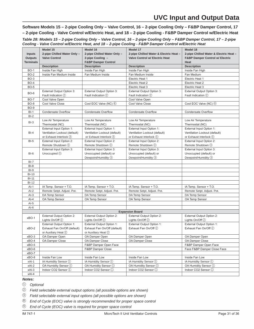
IM 747-1 MicroTech II Unit Ventilator Controls Page 31 of 36
Software Models 15 – 2-pipe Cooling Only – Valve Control, 16 – 2-pipe Cooling Only – F&BP Damper Control, 17 – 2-pipe Cooling - Valve Control w/Electric Heat, and 18 – 2-pipe Cooling - F&BP Damper Control w/Electric Heat Table 28: Models 15 – 2-pipe Cooling Only – Valve Control, 16 – 2-pipe Cooling Only – F&BP Damper Control, 17 – 2-pipe Cooling - Valve Control w/Electric Heat, and 18 – 2-pipe Cooling - F&BP Damper Control w/Electric Heat Model 15 Model 16 Model 17 Model 18 Inputs 2-pipe Chilled Water Only – 2-pipe Chilled Water Only – 2-pipe Chilled Water & Electric Heat – 2-pipe Chilled Water & Electric Heat – Outputs Valve Control 2-pipe Cooling – Valve Control w/ Electric Heat F&BP Damper Control w/ Electric Terminals F&BP Damper Control Heat Description Description Description Description BO-1 Inside Fan High Inside Fan High Inside Fan High Inside Fan High BO-2 Inside Fan Medium Inside Fan Medium Inside Fan Medium Inside Fan Medium BO-3 Electric Heat 1 Electric Heat 1 BO-4 Electric Heat 2 Electric Heat 2 BO-5 Electric Heat 3 Electric Heat 3
BO-6 External Output Option 3: External Output Option 3: External Output Option 3: External Output Option 3:
Fault Indication 2 Fault Indication 2 Fault Indication 2 Fault Indication 2 BO-7 Cool Valve Open Cool Valve Open BO-8 Cool Valve Close Cool EOC Valve (NC) 8 Cool Valve Close Cool EOC Valve (NC) 9 BO-9 BI-1 Condensate Overflow Condensate Overflow Condensate Overflow Condensate Overflow BI-2
BI-3 Low Air Temperature Low Air Temperature Low Air Temperature Low Air Temperature
Thermostat (NC) Thermostat (NC) Thermostat (NC) Thermostat (NC) External Input Option 1: External Input Option 1: External Input Option 1: External Input Option 1: BI-4 Ventilation Lockout (default) Ventilation Lockout (default) Ventilation Lockout (default) Ventilation Lockout (default) or Exhaust Interlock 3 or Exhaust Interlock 3 or Exhaust Interlock 3 or Exhaust Interlock 3 BI-5 External Input Option 2: External Input Option 2: External Input Option 2: External Input Option 2: Remote Shutdown 3 Remote Shutdown 3 Remote Shutdown 3 Remote Shutdown 3 External Input Option 3: External Input Option 3: External Input Option 3: External Input Option 3: BI-6 Unoccupied 3 Unoccupied (default) or Unoccupied (default) or Unoccupied (default) or Dewpoint/Humidity 3 Dewpoint/Humidity 3 Dewpoint/Humidity 3 BI-7 BI-8 BI-9 BI-10 BI-11 BI-12 AI-1 IA Temp. Sensor + T.O. IA Temp. Sensor + T.O. IA Temp. Sensor + T.O. IA Temp. Sensor + T.O. AI-2 Remote Setpt. Adjust. Pot. Remote Setpt. Adjust. Pot. Remote Setpt. Adjust. Pot. Remote Setpt. Adjust. Pot. AI-3 DA Temp Sensor DA Temp Sensor DA Temp Sensor DA Temp Sensor AI-4 OA Temp Sensor OA Temp Sensor OA Temp Sensor OA Temp Sensor AI-5 AI-6 Expansion Board
xBO-1 External Output Option 2: External Output Option 2: External Output Option 2: External Output Option 2:
Lights On/Off 2 Lights On/Off 2 Lights On/Off 2 Lights On/Off 2 External Output Option 1: External Output Option 1: External Output Option 1: External Output Option 1: xBO-2 Exhaust Fan On/Off (default) Exhaust Fan On/Off (default) Exhaust Fan On/Off 2 Exhaust Fan On/Off 2 or Auxiliary Heat 2 or Auxiliary Heat 2 xBO-3 OA Damper Open OA Damper Open OA Damper Open OA Damper Open xBO-4 OA Damper Close OA Damper Close OA Damper Close OA Damper Close xBO-5 F&BP Damper Open Face F&BP Damper Open Face xBO-6 F&BP Damper Close Face F&BP Damper Close Face xBO-7 xBO-8 Inside Fan Low Inside Fan Low Inside Fan Low Inside Fan Low xAI-1 IA Humidity Sensor 1 IA Humidity Sensor 1 IA Humidity Sensor 1 IA Humidity Sensor 1 xAI-2 OA Humidity Sensor 1 OA Humidity Sensor 1 OA Humidity Sensor 1 OA Humidity Sensor 1 xAI-3 Indoor CO2 Sensor 1 Indoor CO2 Sensor 1 Indoor CO2 Sensor 1 Indoor CO2 Sensor 1 xAI-4
Notes: 1 Optional 2 Field selectable external output options (all possible options are shown) 3 Field selectable external input options (all possible options are shown) 8 End of Cycle (EOC) valve is strongly recommended for proper space control 9 End of Cycle (EOC) valve is required for proper space control
UVC Input and Output Data

Page 32 of 36 MicroTech II Unit Ventilator Controls IM 747-1
UVC Configuration ParametersThe UVC has been provided with a number of configuration variables as listed in the following table.For a description of supported network variables for each protocol refer to Protocol Data Packet bulletin, see Table 3Table 29: Unit Ventilator Software Configuration/Variables Software Model UV1 UV2 UV3 UV4 UV5 UV6 UV7
Configuration
Abr. Notes Default 0 2 3 4 5 6 7 8 9 10 11 12 13 14 15 16 17 18 1
Parameter Name
Occupied Cooling Setpoint OCS 73°F(23°C) x x x x x x x x x x x x x x x x x x x Standby Cooling Setpoint SCS 77°F(25°C) x x x x x x x x x x x x x x x x x x x Unoccupied Cooling Setpoint UCS 82°F(28°C) x x x x x x x x x x x x x x x x x x x Occupied Heating Setpoint OHS 70°F(21°C) x x x x x x x x x x x x x x x x x x x Standby Heating Setpoint SHS 66°F(19°C) x x x x x x x x x x x x x x x x x x x Unoccupied Heating Setpoint UHS 61°F(16°C) x x x x x x x x x x x x x x x x x x x usable for network installations Location Label to store descriptive physical unit x x x x x x x x x x x x x x x x x x information (i.e. room number, etc.) Local Bypass Time Tenant Override 240 min x x x x x x x x x x x x x x x x x x Space CO2 Setpoint 2 CO2S 1200 PPM x x x x x x x x x x x x x x x x x x used with both active (reheat) Space Humidity Setpoint 2 RHS and passive dehumidification 60% RH x x x x x x x x x x x sequences 0 = disable, 1 = enable (uses Emergency Heat Enable auxiliary heat where primary 1 x x x x x x x x x x x x x x x x x x x heat is not applicable) Emergency Heat Setpoint EHS 54°F(12°C) x x x x x x x x x x x x x x x x x x x Emergency Heat 0 = no emergency heat during Shutdown Configuration shutdown,1 = available emergency 0 x x x x x x x x x x x x x x x x x x x heat during shutdown Wall Sensor Type 2 0 = +/- 3°F, 1 = 55°F to 85°F 0 x x x x x x x x x x x x x x x x x x x
Slave Type Configuration 2 0 = independent slave,
0 x x x x x x x x x x x x x x x x x x x 1 = dependent slave OAD Min Position (this variable will be factory set High-Speed Setpoint OADH to 5% open when the unit is 20% open x x x x x x x x x x x x x x x x x x x ordered with optional CO2 DCV) OAD Min Position
OADM 30% open x x x x x x x x x x x x x x x x x x x Med-Speed Setpoint OAD Min Position
OADL 35% open x x x x x x x x x x x x x x x x x x x Low-Speed Setpoint Exhaust Interlock OAD OA damper minimum position Min Position Setpoint EOAD when the exhaust interlock 100% open x x x x x x x x x x x x x x x x x x x input is energized Energize Exhaust Fan defines position above which OAD Setpoint OADE exhaust fan output will be 10% open x x x x x x x x x x x x x x x x x x x energized OAD Max Position Setpoint OAMX 100% open x x x x x x x x x x x x x x x x x x x 0 = disable, 1 = enable (this
OAD Lockout Enable variable will be factory set to 1 0 x x x x x x x x x x x x x x x x x x x
when the unit is ordered as a recirc unit with no OAD) OA temperature below which the OA damper will remain OAD Lockout Setpoint OALS closed (this variable will be 36°F(2°C) x x x x x x x x x x x x x x x x x x x factory set to –99°C when the unit is ordered as a recirc unit with no OAD) Economizer Enable 0 = disable, 1 = enable 1 x x x x x x x x x x x x x x x x x x x Economizer OA Temp
ETS 68°F(20°C) x x x x x x x x x x x x x x x x x x x Setpoint Economizer IA/OA Temp
ETD 2°F(1°C) x x x x x x x x x x x x x x x x x x x Differential Economizer Compare DO NOT USE (this variable will Differential be removed in future application 0°F(0°C) x x x x x x x x x x x x x x x x x x x releases)
Notes: 1 Parameters accessible through the LUI 2 Requires optional equipment
UVC Configuration Parameters

IM 747-1 MicroTech II Unit Ventilator Controls Page 33 of 36
Software Model Configuration UV1 UV2 UV3 UV4 UV5 UV6 UV7 Parameter Name Abr. Notes Default
0 2 3 4 5 6 7 8 9 10 11 12 13 14 15 16 17 18 1
Economizer OA EES
25btu/lb x x x x x x x x x x x x x x x x x x x
Enthalpy Setpoint (58kJ/kg) Economizer IA/OA
EED 1.3btu/lb
x x x x x x x x x x x x x x x x x x x Enthalpy Differential (3kJ/kg)
External BI-1 Configuration 0 = Unoccupied,
0
x x x x x x x x x x x x 1 = Dewpoint/Humidity
External BI-3 Configuration 0 = Ventilation Lockout,
0 x x x x x x x x x x x x x x x x x x x 1 = Exhaust Interlock
External BO-1 Configuration 0 = Lights On/Off,
0 x x x x 1 = Motorized Water Valve
External BO-2 Configuration 0 = Fault Indication,
0 x x x x 1 = Pump Restart
External BO-3 Configuration 0 = Auxiliary Heat,
0 x x x x x x x x x x x x x Exhaust Fan On/Off Filter Alarm Enable 0 = disable, 1 = enable 0 x x x x x x x x x x x x x x x x x x x
Filter Change Hours Setpoint fan run hours between filter
700 hrs x x x x x x x x x x x x x x x x x x x change alarms Primary Cool 18°F
x x x x x x x x x x x x x x x x x x Proportional Band (10°C) Primary Cool Integral Time 180 sec x x x x x x x x x x x x x x x x x x Secondary Cool 11°F
x x x x x x x x x x x x x x x Proportional Band (6°C) Secondary Cool Integral Time 600 sec x x x x x x x x x x x x x x x Primary Heat 11°F
x x x x x x x x x x x x x x Proportional Band (6°C) Primary Heat Integral Time 600 sec x x x x x x x x x x x x x x Secondary Heat 11°F
x x Proportional Band (6°C) Secondary Heat Integral Time 600 sec x x Discharge Air Temp 13.5°F
x x x x x x x x x x x x x x x x x x Proportional Band (7.5°C) Discharge Air Temp
900 sec x x x x x x x x x x x x x x x x x x Integral Time CO2 Proportional Band 2 100 PPM x x x x x x x x x x x x x x x x x x CO2 Integral Time 2 600 sec x x x x x x x x x x x x x x x x x x Ventilation Cooling Low
VCLL discharge air low limit during 54°F
x x x x x x x x x x x x x x x x x x x Limit Setpoint ventilation or economizer cooling (12°C) Mechanical Cooling Low discharge air low limit during Limit Setpoint MCLL mechanical (compressor or 45°F (7°C) x x x x x x x x x x x x x x x x hydronic) cooling Discharge Air High Limit DAHL 140°F(60°C) x x x x x x x x x x x x x x x x x x compressor delay to allow a filed Motorized Water Valve Delay installed motorized water 0 sec x x x valve to open Passive Dehum Temp cooling setpoint used during 72°F x x x Setpoint 2 passive dehumidification (22°C) Passive Dehum F&BP maximum F&BP damper face Damper Max 2 position during passive 20% face x x x dehumidification Space Fan On Delay 10 sec x x x Space Fan Off Delay 30 sec x x x x x x x x x x x x x x x x x x space fan operation during occupied, Fan Cycling Configuration standby and bypass occupancy 2 x x x x x x x x x x x x x x x x x x x modes: 2 = continuous, 3 = cycle Space Fan Speed example: 6/60min = 10 min. Changes Per Hour (maximum of 1 fan speed change 6 x x x x x x x x x x x x x x x x x x every 10 min when fan in auto) reset total run time: 1 = reset Space Fan Run Time Reset (you must return the variable 0 x x x x x x x x x x x x x x x x x x back to 0 after reset) reset total run time: 1 = reset Compressor Run Time Reset (you must return the variable 0 x x x x x x x back to 0 after reset)
Notes: 1 Parameters accessible through the LUI 2 Requires optional equipment
UVC Configuration Parameters

Page 34 of 36 MicroTech II Unit Ventilator Controls IM 747-1
Software Model Configuration UV1 UV2 UV3 UV4 UV5 UV6 UV7 Parameter Name Abr. Notes Default
0 2 3 4 5 6 7 8 9 10 11 12 13 14 15 16 17 18 1
Compressor Enable 0 = disable, 1 = enable 1 x x x x x x x Compressor Minimum
180 sec x x x x x x x On Time Compressor Minimum
180 sec x x x x x x x Off Time Compressor Cooling OA temperature below which Lockout Setpoint CCLO compressor cooling is not 61°F (16°C) x x x x x x x allowed Compressor Heating Lockout OA temperature below which Setpoint CHLO compressor heating is 25°F (-4°C) x x not allowed Compressor Envelope 55°F(12.8°C) x x x x x Cool Max In 55°F(12.8°C) x x Compressor Envelope 28°F(-2.2°C) x x x x x Cool Min In 28°F(-2.2°C) x x Compressor Envelope 150°F(65.6°C) x x x x x Cool Max Out 150°F(65.6°C) x x Compressor Envelope 50°F(10.0°C) x x x x x Cool Min Out 50°F(10.0°C) x x Compressor Envelope 0.2 x x x x x Cool Max Ratio 0.2 x x Compressor Envelope 36°F(2.3°C) x x x x x Cool Max Offset 36°F(2.3°C) x x Compressor Envelope 0.0 x x x x x Cool Min Ratio 0.0 x x Compressor Envelope 28°F(-2.2°C) x x x x x Cool Min Offset 28°F(-2.2°C) x x Compressor Envelope 150°F(65.6°C) x Heat Max In 150°F(65.6°C) x x Compressor Envelope 50°F(10°C) x Heat Min In 45°F(7.2°C) x x Compressor Envelope 55°F(12.8°C) x Heat Max Out 55°F(12.8°C) x x Compressor Envelope 10°F(-12.2°C) x Heat Min Out 28°F(-2.2°C) x x Compressor Envelope 0.0 x Heat Max Ratio 0.0 x x Compressor Envelope 150°F(65.6°C) x Heat Max Offset 150°F(65.6°C) x x Compressor Envelope 1.0 x Heat Min Ratio 1.2 x x Compressor Envelope 52°F(11.1°C) x Heat Min Offset 47.5°F(8.6°C) x x Defrost Setpoint 37°F(3°C) x Defrost Time Limit 5 min x Defrost Reset Setpoint 45°F(7°C) x OA temperature below which EOC OAT Low Setpoint EOCS the EOC valve will 39°F(4°C) x x x x x x x remain open differential required between Source (Water-in)
WITD space temperature and source
5°F(3°C) x x x Temp Differential (water in) temp to allow hydronic heating or cooling
Auxiliary Heat Start Differential AHSD degrees below effective heating
2°F(1°C) x x x x x x x x x x x x x setpoint where auxiliary heat ends degrees above auxiliary heat Auxiliary Heat End Differential AHED start point where auxiliary 2°F(1°C) x x x x x x x x x x x x x heat ends Auxiliary Heat Configuration 0 = normally open heat device, (hot water valve, etc.) 1 = normally closed heat device 0 x x x x x x x x x x x x x (electric heat, etc.)
Notes: 1 Parameters accessible through the LUI
UVC Configuration Parameters

IM 747-1 MicroTech II Unit Ventilator Controls Page 35 of 36
Software Model Configuration UV1 UV2 UV3 UV4 UV5 UV6 UV7 Parameter Name Abr. Notes Default
0 2 3 4 5 6 7 8 9 10 11 12 13 14 15 16 17 18 1
0 = disable, 1 = enable (this Space Humidity variable will be factory set to 1
0 x x x x x x x x x x x x x x x x x x
Sensor Enable 2 when the unit is ordered with optional humidity sensor) 0 = disable, 1 = enable (this Outdoor Humidity variable will be factory set to 1 0 x x x x x x x x x x x x x x x x x x Sensor Enable 2 when the unit is ordered with optional humidity sensor) OAD Stroke Time 90 sec x x x x x x x x x x x x x x x x x x F&BP Damper Stroke Time 95 sec x x x x x x WH or CW/HW Valve
76 sec x x x x x x
Stroke Time CW Valve Stroke Time 76 sec x x x x x used on split-system units only to partially disable the compressor envelope by setting the outside Split-System OA/DX Coil Temp condensing unit DX coil 327.67 x x x x x temperature to a fixed valid value. Enter 122°F (50°C) for split-systems. For self-contained units use 327.67 (default). Application Name and Version Label adjust the compressor delay used to prevent multiple Compressor Start Delay compressorized units from
0 sec x x x x x x x x starting simultaneously (each unit or group of units should have a different delay setting) Outdoor Fan On Delay 10 sec x x x x x x x
Notes: 1 Parameters accessible through the LUI 2 Requires optional equipment
UVC Configuration Parameters

© 2013 Daikin Applied • www.DaikinAP.com • (800) 432–1342 IM 747-1 / Page 36 of 36 (10/13)
Daikin Training and Development
Now that you have made an investment in modern, efficient Daikin equipment, its care should be a high priority. For training information on all Daikin HVAC products, please visit us at www.DaikinAP.com and click on training, or call 540-248-9646 and ask for the Training Department.
Warranty
All Daikin equipment is sold pursuant to its standard terms and conditions of sale, including Limited Product Warranty. Consult your local Daikin Representative for warranty details. Refer to Form 933-430285Y. To find your local Daikin Representative, go to www.DaikinAP.com.
Aftermarket Services
To find your local parts office, visit www.DaikinAP.com or call 800-37PARTS (800-377-2787). To find your local service office, visit www.DaikinAPcom or call 800-432-1342.
This document contains the most current product information as of this printing. For the most up-to-date product information, please go to www.DaikinAP.com.
Products manufactured in an ISO Certified Facility.


![Pneumonia (Ventilator-associated [VAP] and non-ventilator](https://img.pdfslide.us/doc/110x75/61c3dfa934191a172140c0d5/pneumonia-ventilator-associated-vap-and-non-ventilator-.jpg)