Embed Size (px)
Citation preview
Applied Surface Science 254 (2008) 6762–6765
Microstructures and multiferroic properties of texturedBi0.8La0.2FeO3 thin films
Yi Zhang, Ling-Hua Pang, Ming-Hui Lu, Zheng-Bin Gu, Shan-Tao Zhang *,Chang-Sheng Yuan, Yan-Feng Chen
National Laboratory of Solid State Microstructures, Department of Materials Science and Engineering, Nanjing University, Nanjing 210093, PR China
A R T I C L E I N F O
Article history:
Received 28 February 2008
Received in revised form 18 April 2008
Accepted 18 April 2008
Available online 1 May 2008
Keywords:
BiFeO3
Microstructure
Multiferroic
La-substituted
A B S T R A C T
La-substituted BiFeO3, Bi0.8La0.2FeO3, thin films were fabricated on Pt/Ti/SiO2/Si substrates by pulsed
laser deposition. X-ray diffraction and high-resolution transmission electron microscope were used to
analyze the structures of the films. The results show the films fabricated under optimized growth
condition are (0 1 2) textured. X-ray photoemission spectroscopy results indicate that the oxidation state
of Fe ion is Fe3+ in the films without detectable Fe2+. The films show low leakage current and excellent
dielectric characters. Multiferroic properties with a remnant ferroelectric polarization of 5.2 mC/cm2 and
a remanent magnetization of 0.02 mB/Fe were established. These results have some implications for
further research.
� 2008 Elsevier B.V. All rights reserved.
Contents lists available at ScienceDirect
Applied Surface Science
journal homepage: www.elsevier .com/locate/apsusc
1. Introduction
Multiferroic materials, which show simultaneously sponta-neous electric and magnetic ordering in one phase, have attractedmuch attention in these years because of its fascinating potentialapplication in such as ferroelectric memory and multi-functionaldevices [1–4]. The typical single-phase multiferroic perovskiteoxides are BiFeO3 (BFO), YMnO3, BiMnO3, etc. Among thesemultiferroic materials, BFO is well studied, because of its high Curietemperature (TC � 1103 K) and Neel temperature (TN � 643 K)[1,5]. BFO is a rhombohedrally distorted ferroelectric perovskitewith the space group R3c (ar = 3.96 A, ar = 0.68) and G-typeantiferromagnetic [2,3]. In thin film form, it has large saturatedpolarization (�80 mC/cm2) at room temperature. But comparingwith its excellent ferroelectric properties, its magnetic propertiesare too weak to reach practical standard [6]. How to enhance themagnetic properties of BFO is becoming much more interesting.
Recently, much work has been done to enhance the magneticproperties of BFO films. Two main methods were reported. One ischemical doping, the other is to fabricate different epitaxialheterostructure films [7,8]. The former method (such as La-substitution for A-site Bi ions) was considered as an effective wayto suppress inhomogeneous magnetic spin structure. The inho-
* Corresponding author.
E-mail address: [email protected] (S.-T. Zhang).
0169-4332/$ – see front matter � 2008 Elsevier B.V. All rights reserved.
doi:10.1016/j.apsusc.2008.04.082
mogeneous magnetic spin structure, which formed by the rotatingoxygen octahedral along [1 1 1] axis with a wavelength of about620 A, will cancel the macroscopic magnetization [3]. In fact, howto suppress the spiral spin structure and get ferromagnetism is oneof the most important issues [3,6,7]. Our recent work shows thatproper La3+-substitution for Bi3+ (Bi0.8La0.2FeO3) can improvemagnetic and ferroelectric properties of BFO ceramics simulta-neously [9].
In this article, we report the microstructures and multiferroicproperties of (0 1 2) textured La-substituted BFO (Bi0.8La0.2FeO3,BLFO) films. The relationship between microstructures andproperties is discussed.
2. Experimental
The film was fabricated by pulsed laser deposition (PLD) on Pt/Ti/SiO2/Si substrates. The BLFO ceramic was used as PLD target. Theceramic was prepared by solid-state reaction with the startingmaterials of Bi2O3, Fe2O3 and La2O3, Bi-excess by 20% to compensateits loss during the process [10]. A Brilliant Nd:YAG laser (Quantel)with 355 nm wavelength was used in the experiment. During eachdeposition, the deposition rate was 10 Hz, the pulse energy was200 mJ, the base pressure was 3 � 10�5 Pa, and the distancebetween substrate and target was 5.5 cm. To optimize growthcondition of BLFO films, different substrate temperatures andflowing oxygen pressures were applied. After deposition, Pt topelectrodes with diameter of 100 mm were sputtered at room
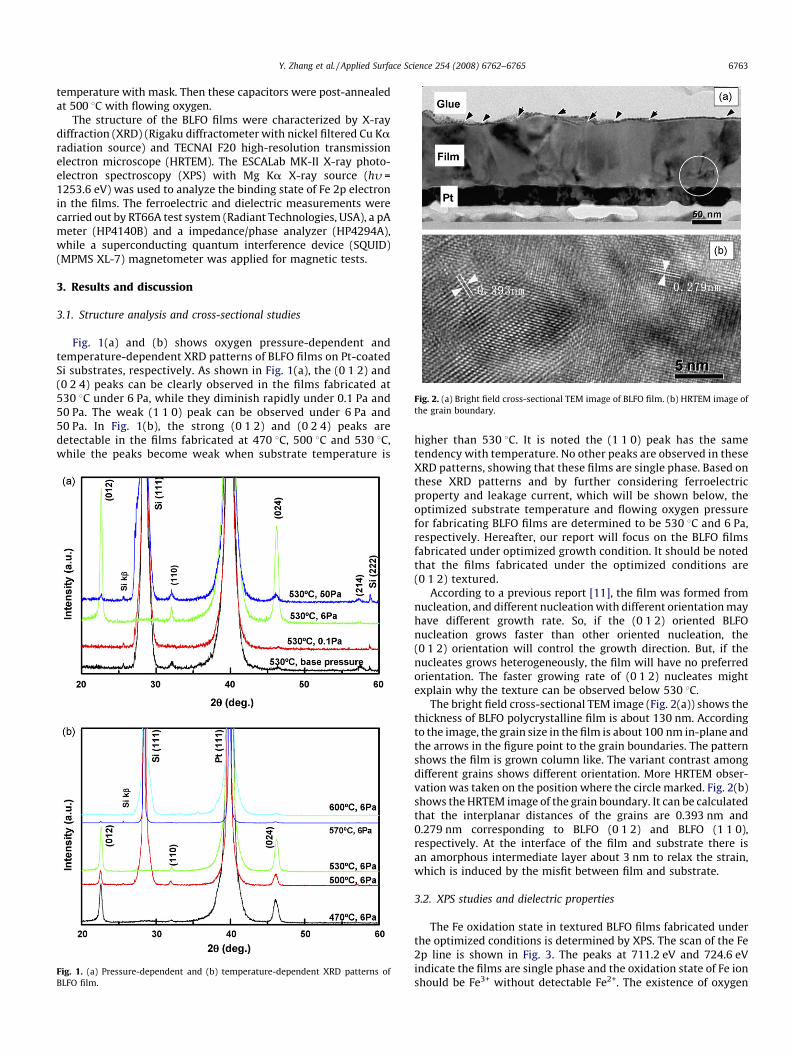
Fig. 2. (a) Bright field cross-sectional TEM image of BLFO film. (b) HRTEM image of
the grain boundary.
Y. Zhang et al. / Applied Surface Science 254 (2008) 6762–6765 6763
temperature with mask. Then these capacitors were post-annealedat 500 8C with flowing oxygen.
The structure of the BLFO films were characterized by X-raydiffraction (XRD) (Rigaku diffractometer with nickel filtered Cu Karadiation source) and TECNAI F20 high-resolution transmissionelectron microscope (HRTEM). The ESCALab MK-II X-ray photo-electron spectroscopy (XPS) with Mg Ka X-ray source (hy =1253.6 eV) was used to analyze the binding state of Fe 2p electronin the films. The ferroelectric and dielectric measurements werecarried out by RT66A test system (Radiant Technologies, USA), a pAmeter (HP4140B) and a impedance/phase analyzer (HP4294A),while a superconducting quantum interference device (SQUID)(MPMS XL-7) magnetometer was applied for magnetic tests.
3. Results and discussion
3.1. Structure analysis and cross-sectional studies
Fig. 1(a) and (b) shows oxygen pressure-dependent andtemperature-dependent XRD patterns of BLFO films on Pt-coatedSi substrates, respectively. As shown in Fig. 1(a), the (0 1 2) and(0 2 4) peaks can be clearly observed in the films fabricated at530 8C under 6 Pa, while they diminish rapidly under 0.1 Pa and50 Pa. The weak (1 1 0) peak can be observed under 6 Pa and50 Pa. In Fig. 1(b), the strong (0 1 2) and (0 2 4) peaks aredetectable in the films fabricated at 470 8C, 500 8C and 530 8C,while the peaks become weak when substrate temperature is
Fig. 1. (a) Pressure-dependent and (b) temperature-dependent XRD patterns of
BLFO film.
higher than 530 8C. It is noted the (1 1 0) peak has the sametendency with temperature. No other peaks are observed in theseXRD patterns, showing that these films are single phase. Based onthese XRD patterns and by further considering ferroelectricproperty and leakage current, which will be shown below, theoptimized substrate temperature and flowing oxygen pressurefor fabricating BLFO films are determined to be 530 8C and 6 Pa,respectively. Hereafter, our report will focus on the BLFO filmsfabricated under optimized growth condition. It should be notedthat the films fabricated under the optimized conditions are(0 1 2) textured.
According to a previous report [11], the film was formed fromnucleation, and different nucleation with different orientation mayhave different growth rate. So, if the (0 1 2) oriented BLFOnucleation grows faster than other oriented nucleation, the(0 1 2) orientation will control the growth direction. But, if thenucleates grows heterogeneously, the film will have no preferredorientation. The faster growing rate of (0 1 2) nucleates mightexplain why the texture can be observed below 530 8C.
The bright field cross-sectional TEM image (Fig. 2(a)) shows thethickness of BLFO polycrystalline film is about 130 nm. Accordingto the image, the grain size in the film is about 100 nm in-plane andthe arrows in the figure point to the grain boundaries. The patternshows the film is grown column like. The variant contrast amongdifferent grains shows different orientation. More HRTEM obser-vation was taken on the position where the circle marked. Fig. 2(b)shows the HRTEM image of the grain boundary. It can be calculatedthat the interplanar distances of the grains are 0.393 nm and0.279 nm corresponding to BLFO (0 1 2) and BLFO (1 1 0),respectively. At the interface of the film and substrate there isan amorphous intermediate layer about 3 nm to relax the strain,which is induced by the misfit between film and substrate.
3.2. XPS studies and dielectric properties
The Fe oxidation state in textured BLFO films fabricated underthe optimized conditions is determined by XPS. The scan of the Fe2p line is shown in Fig. 3. The peaks at 711.2 eV and 724.6 eVindicate the films are single phase and the oxidation state of Fe ionshould be Fe3+ without detectable Fe2+. The existence of oxygen
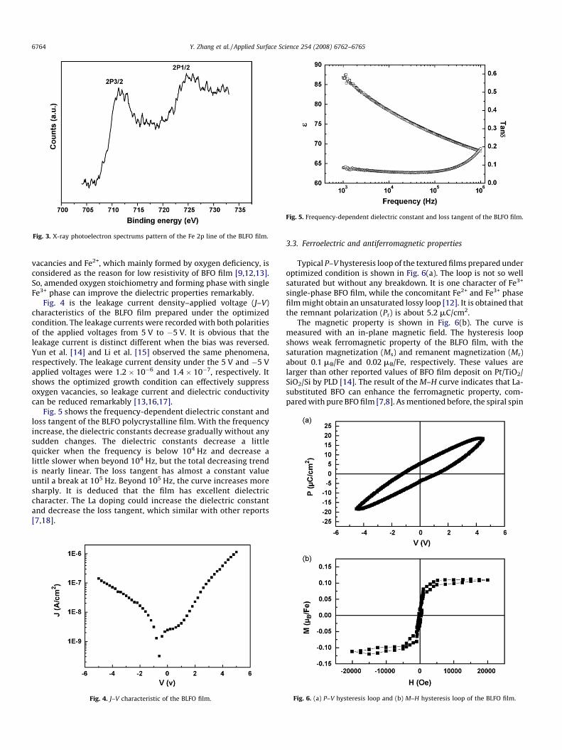
Fig. 3. X-ray photoelectron spectrums pattern of the Fe 2p line of the BLFO film.
Fig. 5. Frequency-dependent dielectric constant and loss tangent of the BLFO film.
Y. Zhang et al. / Applied Surface Science 254 (2008) 6762–67656764
vacancies and Fe2+, which mainly formed by oxygen deficiency, isconsidered as the reason for low resistivity of BFO film [9,12,13].So, amended oxygen stoichiometry and forming phase with singleFe3+ phase can improve the dielectric properties remarkably.
Fig. 4 is the leakage current density–applied voltage (J–V)characteristics of the BLFO film prepared under the optimizedcondition. The leakage currents were recorded with both polaritiesof the applied voltages from 5 V to �5 V. It is obvious that theleakage current is distinct different when the bias was reversed.Yun et al. [14] and Li et al. [15] observed the same phenomena,respectively. The leakage current density under the 5 V and �5 Vapplied voltages were 1.2 � 10�6 and 1.4 � 10�7, respectively. Itshows the optimized growth condition can effectively suppressoxygen vacancies, so leakage current and dielectric conductivitycan be reduced remarkably [13,16,17].
Fig. 5 shows the frequency-dependent dielectric constant andloss tangent of the BLFO polycrystalline film. With the frequencyincrease, the dielectric constants decrease gradually without anysudden changes. The dielectric constants decrease a littlequicker when the frequency is below 104 Hz and decrease alittle slower when beyond 104 Hz, but the total decreasing trendis nearly linear. The loss tangent has almost a constant valueuntil a break at 105 Hz. Beyond 105 Hz, the curve increases moresharply. It is deduced that the film has excellent dielectriccharacter. The La doping could increase the dielectric constantand decrease the loss tangent, which similar with other reports[7,18].
Fig. 4. J–V characteristic of the BLFO film.
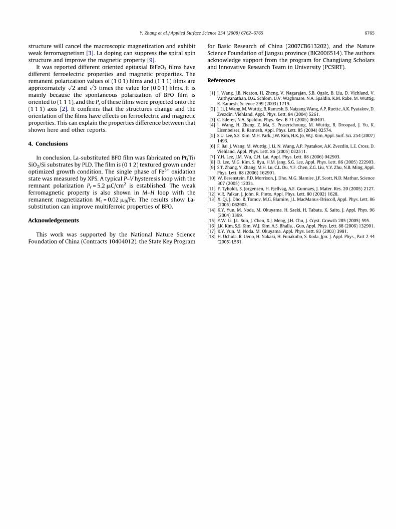
3.3. Ferroelectric and antiferromagnetic properties
Typical P–V hysteresis loop of the textured films prepared underoptimized condition is shown in Fig. 6(a). The loop is not so wellsaturated but without any breakdown. It is one character of Fe3+
single-phase BFO film, while the concomitant Fe2+ and Fe3+ phasefilm might obtain an unsaturated lossy loop [12]. It is obtained thatthe remnant polarization (Pr) is about 5.2 mC/cm2.
The magnetic property is shown in Fig. 6(b). The curve ismeasured with an in-plane magnetic field. The hysteresis loopshows weak ferromagnetic property of the BLFO film, with thesaturation magnetization (Ms) and remanent magnetization (Mr)about 0.1 mB/Fe and 0.02 mB/Fe, respectively. These values arelarger than other reported values of BFO film deposit on Pt/TiO2/SiO2/Si by PLD [14]. The result of the M–H curve indicates that La-substituted BFO can enhance the ferromagnetic property, com-pared with pure BFO film [7,8]. As mentioned before, the spiral spin
Fig. 6. (a) P–V hysteresis loop and (b) M–H hysteresis loop of the BLFO film.
Y. Zhang et al. / Applied Surface Science 254 (2008) 6762–6765 6765
structure will cancel the macroscopic magnetization and exhibitweak ferromagnetism [3]. La doping can suppress the spiral spinstructure and improve the magnetic property [9].
It was reported different oriented epitaxial BiFeO3 films havedifferent ferroelectric properties and magnetic properties. Theremanent polarization values of (1 0 1) films and (1 1 1) films areapproximately
ffiffiffi
2p
andffiffiffi
3p
times the value for (0 0 1) films. It ismainly because the spontaneous polarization of BFO film isoriented to (1 1 1), and the Pr of these films were projected onto the(1 1 1) axis [2]. It confirms that the structures change and theorientation of the films have effects on ferroelectric and magneticproperties. This can explain the properties difference between thatshown here and other reports.
4. Conclusions
In conclusion, La-substituted BFO film was fabricated on Pt/Ti/SiO2/Si substrates by PLD. The film is (0 1 2) textured grown underoptimized growth condition. The single phase of Fe3+ oxidationstate was measured by XPS. A typical P–V hysteresis loop with theremnant polarization Pr = 5.2 mC/cm2 is established. The weakferromagnetic property is also shown in M–H loop with theremanent magnetization Mr = 0.02 mB/Fe. The results show La-substitution can improve multiferroic properties of BFO.
Acknowledgements
This work was supported by the National Nature ScienceFoundation of China (Contracts 10404012), the State Key Program
for Basic Research of China (2007CB613202), and the NatureScience Foundation of Jiangsu province (BK2006514). The authorsacknowledge support from the program for Changjiang Scholarsand Innovative Research Team in University (PCSIRT).
References
[1] J. Wang, J.B. Neaton, H. Zheng, V. Nagarajan, S.B. Ogale, B. Liu, D. Viehland, V.Vaithyanathan, D.G. Schlom, U.V. Waghmare, N.A. Spaldin, K.M. Rabe, M. Wuttig,R. Ramesh, Science 299 (2003) 1719.
[2] J. Li, J. Wang, M. Wuttig, R. Ramesh, B. Naigang Wang, A.P. Ruette, A.K. Pyatakov, D.Zvezdin, Viehland, Appl. Phys. Lett. 84 (2004) 5261.
[3] C. Ederer, N.A. Spaldin, Phys. Rev. B 71 (2005) 060401.[4] J. Wang, H. Zheng, Z. Ma, S. Prasertchoung, M. Wuttig, R. Droopad, J. Yu, K.
Eisenbeiser, R. Ramesh, Appl. Phys. Lett. 85 (2004) 02574.[5] S.U. Lee, S.S. Kim, M.H. Park, J.W. Kim, H.K. Jo, W.J. Kim, Appl. Surf. Sci. 254 (2007)
1493.[6] F. Bai, J. Wang, M. Wuttig, J. Li, N. Wang, A.P. Pyatakov, A.K. Zvezdin, L.E. Cross, D.
Viehland, Appl. Phys. Lett. 86 (2005) 032511.[7] Y.H. Lee, J.M. Wu, C.H. Lai, Appl. Phys. Lett. 88 (2006) 042903.[8] D. Lee, M.G. Kim, S. Ryu, H.M. Jang, S.G. Lee, Appl. Phys. Lett. 86 (2005) 222903.[9] S.T. Zhang, Y. Zhang, M.H. Lu, C.L. Du, Y.F. Chen, Z.G. Liu, Y.Y. Zhu, N.B. Ming, Appl.
Phys. Lett. 88 (2006) 162901.[10] W. Eerenstein, F.D. Morrison, J. Dho, M.G. Blamire, J.F. Scott, N.D. Mathur, Science
307 (2005) 1203a.[11] F. Tyholdt, S. Jorgensen, H. Fjellvag, A.E. Gunnaes, J. Mater. Res. 20 (2005) 2127.[12] V.R. Palkar, J. John, R. Pinto, Appl. Phys. Lett. 80 (2002) 1628.[13] X. Qi, J. Dho, R. Tomov, M.G. Blamire, J.L. MacManus-Driscoll, Appl. Phys. Lett. 86
(2005) 062903.[14] K.Y. Yun, M. Noda, M. Okuyama, H. Saeki, H. Tabata, K. Saito, J. Appl. Phys. 96
(2004) 3399.[15] Y.W. Li, J.L. Sun, J. Chen, X.J. Meng, J.H. Chu, J. Cryst. Growth 285 (2005) 595.[16] J.K. Kim, S.S. Kim, W.J. Kim, A.S. Bhalla, . Guo, Appl. Phys. Lett. 88 (2006) 132901.[17] K.Y. Yun, M. Noda, M. Okuyama, Appl. Phys. Lett. 83 (2003) 3981.[18] H. Uchida, R. Ueno, H. Nakaki, H. Funakubo, S. Koda, Jpn. J. Appl. Phys., Part 2 44
(2005) L561.