Embed Size (px)
Citation preview
A
(wrtXwA©
K
1
lafnowbsfwctptjm
0d
Materials Science and Engineering A 477 (2008) 243–249
Microstructure and properties of friction stir butt-weldedAE42 magnesium alloy
R.P. Dobriyal a, B.K. Dhindaw a,∗, S. Muthukumaran b, S.K. Mukherjee b
a Metallurgy and Materials Engineering Department, Indian Institute of Technology, Kharagpur, Indiab Department of Production Engineering, Birla Institute of Technology, Mesra, Ranchi, India
Received 19 February 2007; received in revised form 7 May 2007; accepted 11 June 2007
bstract
The aim of the present work was to develop a friction stir joint and to investigate the microstructural and mechanical properties of magnesiumAE42 Mg alloy) sheets joined by friction stir welding (FSW). The two sheets, aligned perpendicular to the welding directions, have been successfullyelded. Light optical microscopy was used to observe and study the weld zone characteristics. Dynamic recrystallisation was observed in the weld
egion as well as in the thermo-mechanical heat-affected zone (TMAZ). There was a clear decrease in the precipitate size from the base materialhrough the TMAZ and into the weld zone. The precipitates observed were �-Mg Al , Al Ce and Al Ce. The welds were free of porosities.
17 12 11 3 2RD, SEM and TEM characterization performed on the weld region showed the presence of intermetallic phases. Vickers micro-hardness testingas done along the thickness (transverse direction) of the plate in the weld region to study and understand the variation of hardness with thickness.good correlation between the precipitate size and micro-hardness was observed. 2007 Published by Elsevier B.V.
lloy; S
cp
mepe
oad(stfd
eywords: Friction stir welding; Optical microscopy; Micro-hardness; AE42 a
. Introduction
Magnesium alloys have many attractive properties, such asow density and high specific strength. It is predicted that thepplication of magnesium alloys will grow rapidly in the nearuture, especially in the automotive industry [1]. Presently, mag-esium alloy parts are mainly produced by casting, and the usef other manufacture technologies, such as plastic forming andelding, is still limited. This is one of the main limitations forroadening the application of magnesium alloys. It is neces-ary to develop effective and inexpensive welding techniquesor industrial application of magnesium alloys. Friction stirelding (FSW), a novel solid joining technology is a potential
andidate since it has many advantages compared with the tradi-ional fusion welding. As a solid state joining process, FSW canroduce pore-free joints, since pores caused by metal solidifica-
ion are eliminated. Furthermore, it is an environmental-friendlyoining technology, since neither shielding gas nor consumableaterial is required and no fumes are produced during the pro-
∗ Corresponding author. Tel.: +91 3222283258; fax: +913222282280.E-mail address: [email protected] (B.K. Dhindaw).
whapsrp
921-5093/$ – see front matter © 2007 Published by Elsevier B.V.oi:10.1016/j.msea.2007.06.028
EM characterization
essing. The process itself is described in more detail in earlierublications [3–7].
FSW involves complex material movement and plastic defor-ation. Welding parameters, tool geometry, and joint design
xert significant effect on the material flow pattern and tem-erature distribution, thereby influencing the microstructuralvolution of material.
Tool geometry is the most influential aspect of process devel-pment. The tool geometry plays a critical role in material flownd in turn governs the traverse rate at which FSW can be con-ucted. As mentioned earlier, the tool has two primary functions:a) localized heating, and (b) material flow [3]. In the initialtage of tool plunge, the heating results primarily from the fric-ion between pin and workpiece. Some additional heating resultsrom deformation of material. The tool is plunged till the shoul-er touches the workpiece. The friction between the shoulder andorkpiece results in the biggest component of heating. From theeating aspect, the relative size of pin and shoulder is important,nd the other design features are not critical. The shoulder also
rovides confinement for the heated volume of material. Theecond function of the tool is to ‘stir’ and ‘move’ the mate-ial. The uniformity of microstructure and properties as well asrocess loads are governed by the tool design.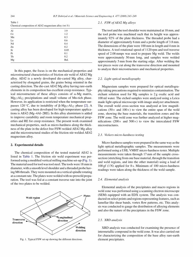
244 R.P. Dobriyal et al. / Materials Science and
Table 1Chemical composition of AE42 magnesium alloy (wt.%)
Al 3.9Ce 1.2Mn 0.3La 0.6Nd 0.4Zn 0.2Si 0.05Pr 0.1TM
maaceiMHpcttemnam
2
lfTdiaro
2
tidTtswatt
2
pe1mTczFnm
2
lpmsa1r
h 0.2g Bal.
In this paper, the focus is on the mechanical properties andicrostructural characteristics of friction stir weld of AE42 Mg
lloy. AE42 is a newly developed die-casted Mg alloy, char-cterized by elongated grains, the grains being oriented in theasting direction. The die-cast AE42 Mg alloy having rare-earthlements in its composition has excellent creep resistance. Typ-cal microstructure of these alloys consists of �-Mg matrix,
g17Al12 precipitations and small volume of Mn-rich phase.owever, its application is restricted when the temperature sur-asses 120 ◦C, due to instability of �-Mg17Al12 phase [2]. Aasting alloy has been developed for high-temperature applica-ions is AE42 (Mg–4Al–2RE). In this alloy aluminium is addedo improve castability and room temperature mechanical prop-rties and RE for creep resistance. The present work examinedechanical properties, such as micro-hardness along the thick-
ess of the plate in the defect free FSW-welded AE42 Mg alloynd the microstructural studies of the friction stir-welded AE42agnesium alloy.
. Experimental details
The chemical composition of the tested material AE42 isisted in Table 1. The friction stir weld experiment was per-ormed using a modified vertical milling machine set-up (Fig. 1).he material used for tool was tool steel. The tools were 18 mm iniameter, with a smooth level shoulder and a threaded probe hav-
ng M6 threads. They were mounted on a vertical spindle rotatingt a constant rate. The plates were welded with no preweld prepa-ation. The tool was fed at a constant traverse rate into the jointf the two plates to be welded.Fig. 1. Typical FSW set-up showing the different directions.
2
w(dlsa
2
ife
Engineering A 477 (2008) 243–249
.1. FSW of AE42 Mg alloys
The tool and the tool shoulder were maintained at 18 mm, andhe tool probe was machined such that its height was approx-mately 92% of the plate thickness. The threaded probe had aiameter of approximately 6 mm and a probe length of 3.8 mm.he dimensions of the plate were 100 mm in length and 4 mm in
hickness. A tool rotational speed of 1120 rpm and tool traversepeed of 2.08 mmps was used to prepare Mg weld. The weldsere approximately 50 mm long, and samples were welded
pproximately 5 mm from the starting edge. After welding theest pieces were cut along the transverse direction and mountedo analyze their microstructures and mechanical properties.
.2. Light optical metallography
Magnesium samples were prepared for optical metallogra-hy taking precautions required to minimize contamination. Thetchant solution used for Mg samples is 2 g oxalic acid and00 ml water. The etched samples were analyzed using a Leicaade light optical microscope with image analyzer attachment.he overall weld cross-section was analyzed at low magnifi-ations (50× and 100×) to view the entire span of the weldone, showing the base materials, the transition zones and theSW zone. The weld zone was further analyzed at higher mag-ifications (200× and 500×) to view the intercalated FSWicrostructures.
.3. Vickers micro-hardness testing
Micro-hardness samples were prepared in the same way as theight optical metallographic samples. The measurements wereerformed using a UHL VMHT micro-hardness tester. Multipleeasurements were taken through 17 mm of the sample cross-
ection (stretching from one base material, through the transitionnd weld regions, and into the other material) using a load of00 gf (1 N) applied for 8 s. Minimum of 100 micro-hardnesseadings were taken along the thickness of the weld sample.
.4. Elemental analysis
Elemental analysis of the precipitates and macro regions ineld zone was performed using a scanning electron microscope
SEM) equipped with an EDX system. The analysis was con-ucted on select points and regions representing features, such asamellar-like shear bands, vortex flow patterns, etc. This analy-is was conducted to gauge the distribution of alloying elementsnd also the nature of the precipitates in the FSW zone.
.5. XRD analysis
XRD analysis was conducted for examining the presence ofntermetallic compound in the weld zone. It was also carried outor characterizing the composition of the base alloy rare-earthlement precipitates.
R.P. Dobriyal et al. / Materials Science and Engineering A 477 (2008) 243–249 245
join
2
miee
3
3
Fo
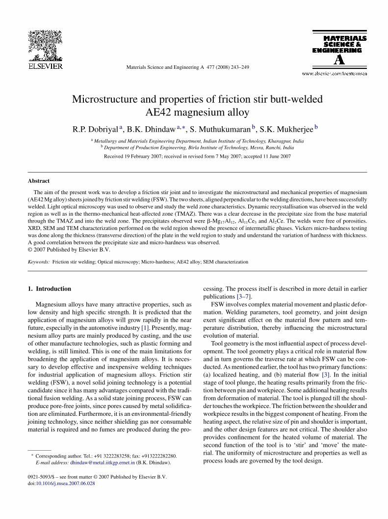
Fig. 2. Typical appearance of the AE42 FSW
.6. Transmission electron microscopy
Thin foils for examining in high-resolution transmission
icroscope were prepared from the weld nugget zone by grind-ng and twin jet electro-polishing. The thinned samples werexamined with a JEOL HRTEM, equipped with EDX spectrom-ter.
i2
ig. 3. Microstructures of magnesium alloy sample. (a) Base metal, (b) TMAZ, (c) wef base metal at higher magnification, and (f) weld nugget at higher magnification.
t on (a) top surface and (b) bottom surface.
. Results and discussions
.1. Weld appearance
Fig. 2 shows the welded joint appearance with process-ng parameters as tool speed 1120 rpm, tool traverse speed as.08 mmps and shoulder diameter as 18 mm. When process-
ld nugget, (d) vortex motion around the pin in weld nugget zone, (e) precipitates
246 R.P. Dobriyal et al. / Materials Science and Engineering A 477 (2008) 243–249
sis o
iAsogwu
hr
F
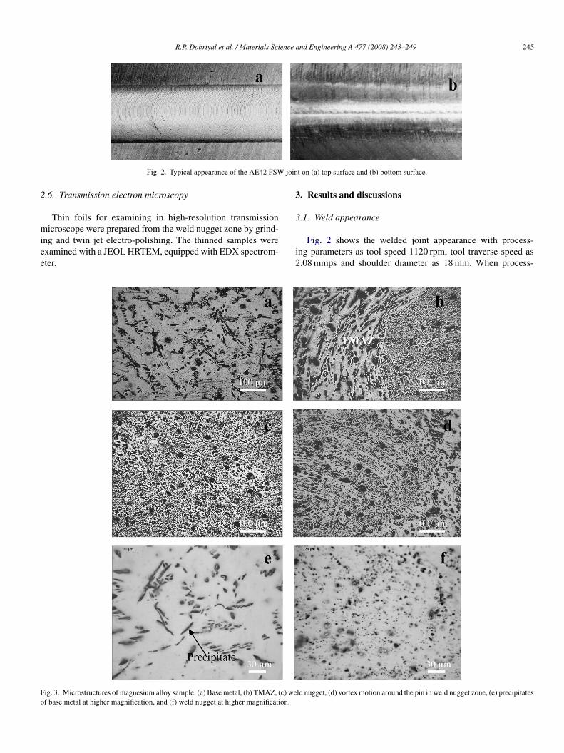
Fig. 4. (a) TEM image of FSW region, (b) EDX analy
ng parameters were proper, the FSW-welded magnesium alloyE42 joint had an excellent appearance, without distortion, as
hown in Fig. 2(a). No macro defects such as void, cracking
r distortions were observed on the surface. Fig. 2(b) shows aood fusion area on the bottom of the joint. The weld zone wasider near the upper surface than the lower surface because thepper surface experienced extreme deformation and frictional3
n
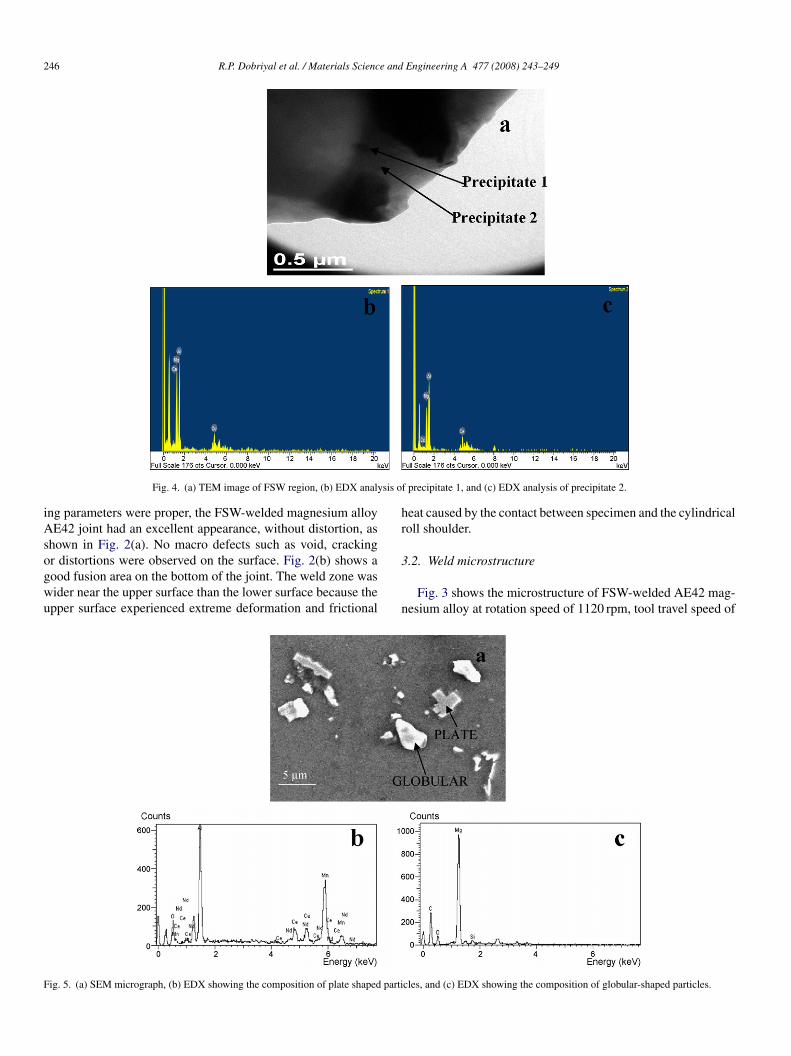
ig. 5. (a) SEM micrograph, (b) EDX showing the composition of plate shaped parti
f precipitate 1, and (c) EDX analysis of precipitate 2.
eat caused by the contact between specimen and the cylindricaloll shoulder.
.2. Weld microstructure
Fig. 3 shows the microstructure of FSW-welded AE42 mag-esium alloy at rotation speed of 1120 rpm, tool travel speed of
cles, and (c) EDX showing the composition of globular-shaped particles.
R.P. Dobriyal et al. / Materials Science and Engineering A 477 (2008) 243–249 247
20 rp
2d
ztttrTtsF
ttpism(v
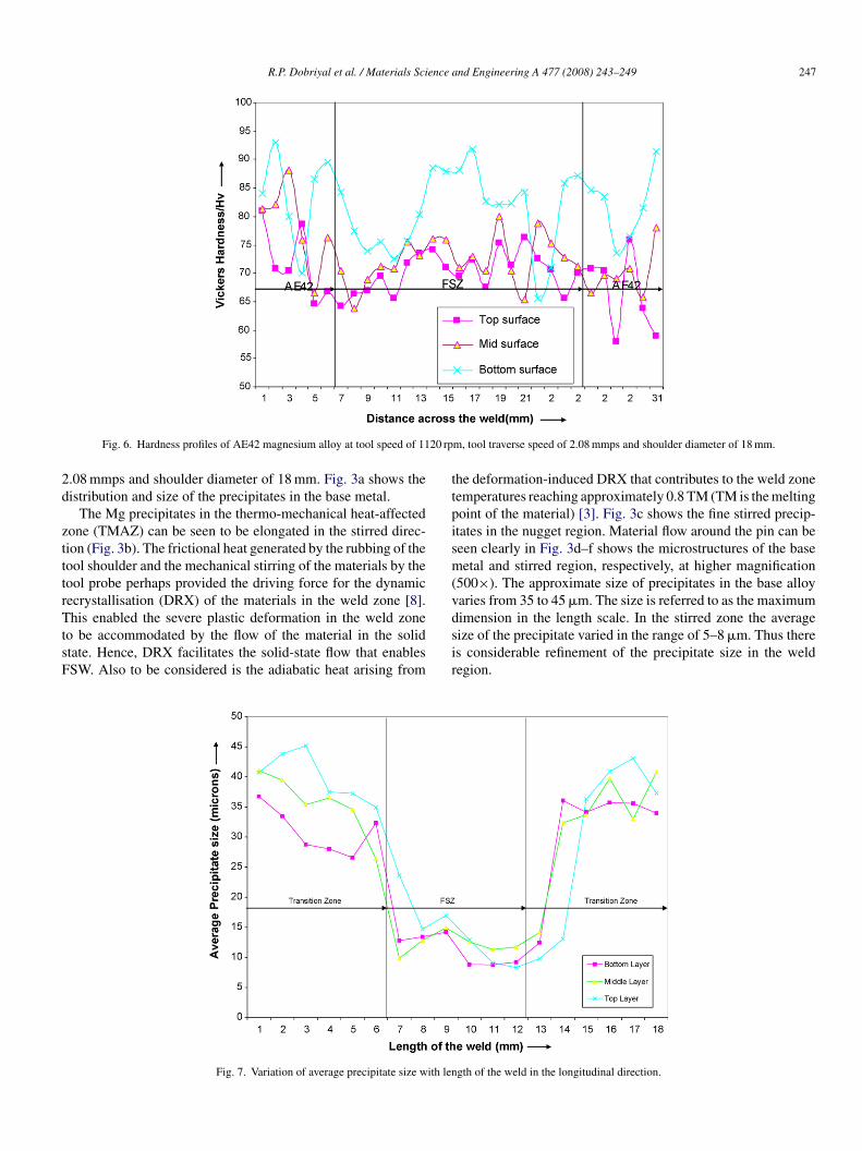
Fig. 6. Hardness profiles of AE42 magnesium alloy at tool speed of 11
.08 mmps and shoulder diameter of 18 mm. Fig. 3a shows theistribution and size of the precipitates in the base metal.
The Mg precipitates in the thermo-mechanical heat-affectedone (TMAZ) can be seen to be elongated in the stirred direc-ion (Fig. 3b). The frictional heat generated by the rubbing of theool shoulder and the mechanical stirring of the materials by theool probe perhaps provided the driving force for the dynamicecrystallisation (DRX) of the materials in the weld zone [8].
his enabled the severe plastic deformation in the weld zoneo be accommodated by the flow of the material in the solidtate. Hence, DRX facilitates the solid-state flow that enablesSW. Also to be considered is the adiabatic heat arising from
dsir
Fig. 7. Variation of average precipitate size with len
m, tool traverse speed of 2.08 mmps and shoulder diameter of 18 mm.
he deformation-induced DRX that contributes to the weld zoneemperatures reaching approximately 0.8 TM (TM is the meltingoint of the material) [3]. Fig. 3c shows the fine stirred precip-tates in the nugget region. Material flow around the pin can beeen clearly in Fig. 3d–f shows the microstructures of the baseetal and stirred region, respectively, at higher magnification
500×). The approximate size of precipitates in the base alloyaries from 35 to 45 �m. The size is referred to as the maximum
imension in the length scale. In the stirred zone the averageize of the precipitate varied in the range of 5–8 �m. Thus theres considerable refinement of the precipitate size in the weldegion.gth of the weld in the longitudinal direction.
2 e and Engineering A 477 (2008) 243–249
mftbidapta
spgso
3
ttt
stonrta
lsbt
Fc
b
48 R.P. Dobriyal et al. / Materials Scienc
Fig. 4 shows the TEM images of friction stir-welded AE42agnesium alloy sample. Ultrafine precipitates of the order of
ew nanometers can be seen in the image. Thus it can be seenhat in the FSW regions precipitates of nanometer size coulde obtained. The presence of nanosize precipitates may be anndication of the phenomena that precipitate dissolution duringynamic recrystallisation, then reprecipitate and some are notble to grow to large sizes. EDX analysis was done on the finerrecipitates to check their composition. It was observed fromhe EDX studies as seen in Fig. 4(b) and (c) that precipitates 1nd 2 are the compound of Al and Ce.
Fig. 5 shows SEM–EDX analysis of the different types andhapes of precipitates of the AE42 magnesium alloy in thelate. It was observed that some are plate shaped and some arelobular-shaped precipitates. EDX studies show that globularhaped are magnesium oxides, and plate shaped are compoundsf rare-earth elements as seen in Fig. 5(b) and (c).
.3. Weld mechanical property
It was found that the hardness varied when we move fromop surface of the weld to bottom surface of the weld along thehickness. A typical hardness profiles at different depths alonghe thickness are shown in Fig. 6.
The above graph is plotted between Vickers hardness ver-us distance across the weld. Different sets of readings wereaken along the thickness of the plate in the weld region. It wasbserved that bottom layer of FSW region had the highest hard-ess as compared to the top and the middle layers. High coolingate at the bottom layers, as suggested else where [9], could behe possible reason for this kind of distribution. Hardness valuesre generally in the range of 58–93 Hv.
Fig. 7 shows the plot of precipitate size variation along the
ength of the weld. It can be seen that the friction stirred regionhows the presence of fine precipitates. It also shows that theottom layer has finer precipitates as compared to the top andhe middle layers.edlr
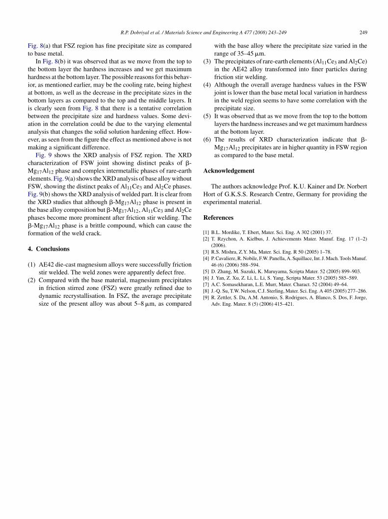
Fig. 9. XRD analysis of (a) base
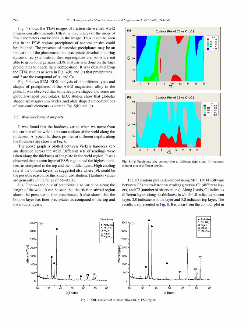
ig. 8. (a) Precipitate size contour plot at different depths and (b) hardnessontour plot at different depths.
The 3D contour plot is developed using Mini Tab14 softwareetween C3 (micro-hardness readings) versus C1 (different lay-rs) and C2 (number of observations). Along Y-axis, C1 indicates
ifferent layers along the thickness in which 1.0 indicates bottomayer, 2.0 indicates middle layer and 3.0 indicates top layer. Theesults are presented in Fig. 8. It is clear from the contour plot inalloy and (b) FSZ region.
ence a
Ft
thiabibaaem
cMeFFttp�f
4
(
(
(
(
(
(
A
He
R
[[
[[
[
R.P. Dobriyal et al. / Materials Sci
ig. 8(a) that FSZ region has fine precipitate size as comparedo base metal.
In Fig. 8(b) it was observed that as we move from the top tohe bottom layer the hardness increases and we get maximumardness at the bottom layer. The possible reasons for this behav-or, as mentioned earlier, may be the cooling rate, being highestt bottom, as well as the decrease in the precipitate sizes in theottom layers as compared to the top and the middle layers. Its clearly seen from Fig. 8 that there is a tentative correlationetween the precipitate size and hardness values. Some devi-tion in the correlation could be due to the varying elementalnalysis that changes the solid solution hardening effect. How-ver, as seen from the figure the effect as mentioned above is notaking a significant difference.Fig. 9 shows the XRD analysis of FSZ region. The XRD
haracterization of FSW joint showing distinct peaks of �-g17Al12 phase and complex intermetallic phases of rare-earth
lements. Fig. 9(a) shows the XRD analysis of base alloy withoutSW, showing the distinct peaks of Al11Ce3 and Al2Ce phases.ig. 9(b) shows the XRD analysis of welded part. It is clear from
he XRD studies that although �-Mg17Al12 phase is present inhe base alloy composition but �-Mg17Al12, Al11Ce3 and Al2Cehases become more prominent after friction stir welding. The-Mg17Al12 phase is a brittle compound, which can cause the
ormation of the weld crack.
. Conclusions
1) AE42 die-cast magnesium alloys were successfully frictionstir welded. The weld zones were apparently defect free.
2) Compared with the base material, magnesium precipitatesin friction stirred zone (FSZ) were greatly refined due todynamic recrystallisation. In FSZ, the average precipitatesize of the present alloy was about 5–8 �m, as compared
[[[[
nd Engineering A 477 (2008) 243–249 249
with the base alloy where the precipitate size varied in therange of 35–45 �m.
3) The precipitates of rare-earth elements (Al11Ce3 and Al2Ce)in the AE42 alloy transformed into finer particles duringfriction stir welding.
4) Although the overall average hardness values in the FSWjoint is lower than the base metal local variation in hardnessin the weld region seems to have some correlation with theprecipitate size.
5) It was observed that as we move from the top to the bottomlayers the hardness increases and we get maximum hardnessat the bottom layer.
6) The results of XRD characterization indicate that �-Mg17Al12 precipitates are in higher quantity in FSW regionas compared to the base metal.
cknowledgement
The authors acknowledge Prof. K.U. Kainer and Dr. Norbertort of G.K.S.S. Research Centre, Germany for providing the
xperimental material.
eferences
1] B.L. Mordike, T. Ebert, Mater. Sci. Eng. A 302 (2001) 37.2] T. Rzychon, A. Kiełbus, J. Achievements Mater. Manuf. Eng. 17 (1–2)
(2006).3] R.S. Mishra, Z.Y. Ma, Mater. Sci. Eng. R 50 (2005) 1–78.4] P. Cavaliere, R. Nobile, F.W. Panella, A. Squillace, Int. J. Mach. Tools Manuf.
46 (6) (2006) 588–594.5] D. Zhang, M. Suzuki, K. Maruyama, Scripta Mater. 52 (2005) 899–903.
6] J. Yan, Z. Xu, Z. Li, L. Li, S. Yang, Scripta Mater. 53 (2005) 585–589.7] A.C. Somasekharan, L.E. Murr, Mater. Charact. 52 (2004) 49–64.8] J.-Q. Su, T.W. Nelson, C.J. Sterling, Mater. Sci. Eng. A 405 (2005) 277–286.9] R. Zettler, S. Da, A.M. Antonio, S. Rodrigues, A. Blanco, S. Dos, F. Jorge,Adv. Eng. Mater. 8 (5) (2006) 415–421.