Embed Size (px)
Citation preview
NASA-TM-II2786
Microstructure and phase stability of single crystal NiA!
alloyed with Hf and Zr
I.E. LocciCase Western Reser_,e University, Cleveland. Ohio 44106, and NASA Lewis Research Center,Cleveland, Ohio 44135
R.M. DickersonNYMA, Inc.. Cleveland, Ohio 44124
A. Garg, R.D. Noebe, J. D. Whittenberger, and M.V. NathalNASA Lewis Research Center, Cleveland, Ohio 44135
R. DaroliaGeneral Electric Aircraft Engines, Cincinnati. Ohio 45215
(Received 26 January 1996; accepted 24 July 1996)
Six near stoichiometric, NiAI single-crystal alloys, with 0.05-1.5 at.% of Hf
and Zr additions plus Si impurities, were microstructurally analyzed in the as-cast,
homogenized, and aged conditions. Hafnium-rich interdendritic regions, containing
the Heusler phase (Ni2AIHf), were found in all the as-cast alloys containing Hf.
Homogenization heat treatments partially reduced these interdendritic segregated
regions. Transmission electron microscopy (TEM) observations of the as-cast andhomogenized microstructures revealed the presence of a high density of fine Hf
(or Zr) and Si-rich precipitates. These were identified as G-phase, Nil6X6Si7, oras an orthorhombic NiXSi phase, where X is Hf or Zr. Under these conditions the
expected Heusler phase (/3 _) was almost completely absent. The Si responsible forthe formation of the G and NiHfSi phases is the result of molten metal reacting with
the Si-containing crucible used during the casting process. Varying the cooling rates
after homogenization resulted in the refinement or complete suppression of the G andNiHfSi phases. In some of the alloys studied, long-term aging heat treatments resulted in
the formation of Heusler precipitates, which were more stable at the aging temperature
and coarsened at the expense of the G-phase. In other alloys, long-term aging resultedin the formation of the NiXSi phase. The stability of the Heusler or NiXSi phases can
be traced to the reactive element (Hf or Zr) to silicon ratio. If the ratio is high, then the
Heusler phase appears stable after long time aging. If the ratio is low, then the NiHfSi
phase appears to be the stable phase.
I. INTRODUCTION
NiA1 alloys, regarded as potential candidates for
high temperature applications, require improvement in
room temperature ductility or toughness as well as high
temperature creep resistance to compete with today's
superalloys. NiAI is one of the few intermetallic al-
loys that possesses excellent oxidation resistance at bothintermediate and high temperatures mainly due to the
formation of a protective A1203 scale, t'2 While theisothermal oxidation resistance of NiA1 is outstanding,
the cyclic oxidation resistance of NiAI is equally im-
pressive when trace additions of reactive elements are
present. Ternary additions, especially from group IV and
V refractory metal elements, have also been shown to
provide significant strengthening at high temperatures.
In particular, the effect of Hf additions on the high tem-
perature mechanical properties of polycrystalline NiA1was suggested to be very important, 3 although creep tests
at slower strain rates indicated that a polycrystalline,
fine-grained Ni-47AI-0.8Hf (at. %) alloy was weaker
than expected. 4 Similar results have been obtained on
NiAI-Zr alloys where significant strengthening was ob-served at lower temperatures and higher strain rates,
but with a much smaller advantage at high temperatures
and low strain rate conditions. 5 Because grain boundary
sliding contributes significantly to the creep rate, itis envisioned that the observed weakness in the latter
studies could be circumvented through the use of single
crystals.Directional solidification has been used to produce
NiAI single crystals for use in aeroturbine engines, inmuch the same way as many commercial superalloys. 6-8
Several difficult milestones, however, have to be met
before single crystal NiA1 alloys can reach commer-
cial use in engines. A balance of properties, including
ductility, toughness, and high temperature strength, as
3024 J. Mater. Res., Vol. 11, No. 12, Dec 1996 © 1996 Materials Research Society
https://ntrs.nasa.gov/search.jsp?R=19970023976 2018-06-02T23:43:52+00:00Z
I.E. Locciet aZ.Microstructureandphasestabilityof singlecrystalNiAI
well as controlled processing, refined joining techniques,and precise machining of NiAI are required before thismaterial will be widely accepted. The first challengeis to produce a single crystal NiA1 alloy with a con-trolled chemistry. Several processing techniques, suchas Bridgman, Czochralski, modified edge-defined film-
fed growth, and the containerless float zone process areavailable to produce NiAI single crystals. 9.1° However,the high melting point of NiA1, close to 1912 K which is
about 300 K higher than the temperature used to processsuperalloys, pushes the stability of ceramic molds to theirlimit when in contact with molten NiAI. _1,_2Therefore,even when single crystal processing is successful, mold-metal reactions are serious issues.
Consequently, the current research focuses on thecharacterization of the phases present after directional
solidification of NiAI-Zr/Hf alloys and their stability,which is expected to play an important role in thehigh temperature behavior of these NiAI single crys-tals. A follow-up publication will discuss the elevatedtemperature deformation properties of Hf-modified, NiAIsingle-crystal alloys. Preliminary results were publishedpreviously. _-15
II, EXPERIMENTAL PROCEDURE
Single-crystal ingots from three alloy systems(Table I) were microstructurally characterized by opticalmicroscopy, scanning electron microscopy (SEM), andtransmission electron microscopy (TEM). The first
system is represented by four NiAl-Hf alloys containing0.1, 0.3, 1.0, or 1.5 atomic percent (at.%) Hf (alloydescriptions in the text are nominal compositions).The second system consisted of a NiAI-0.05 at. %
Zr alloy, which is considered one of the best alloysfor cyclic oxidation resistance. _,2 The third system
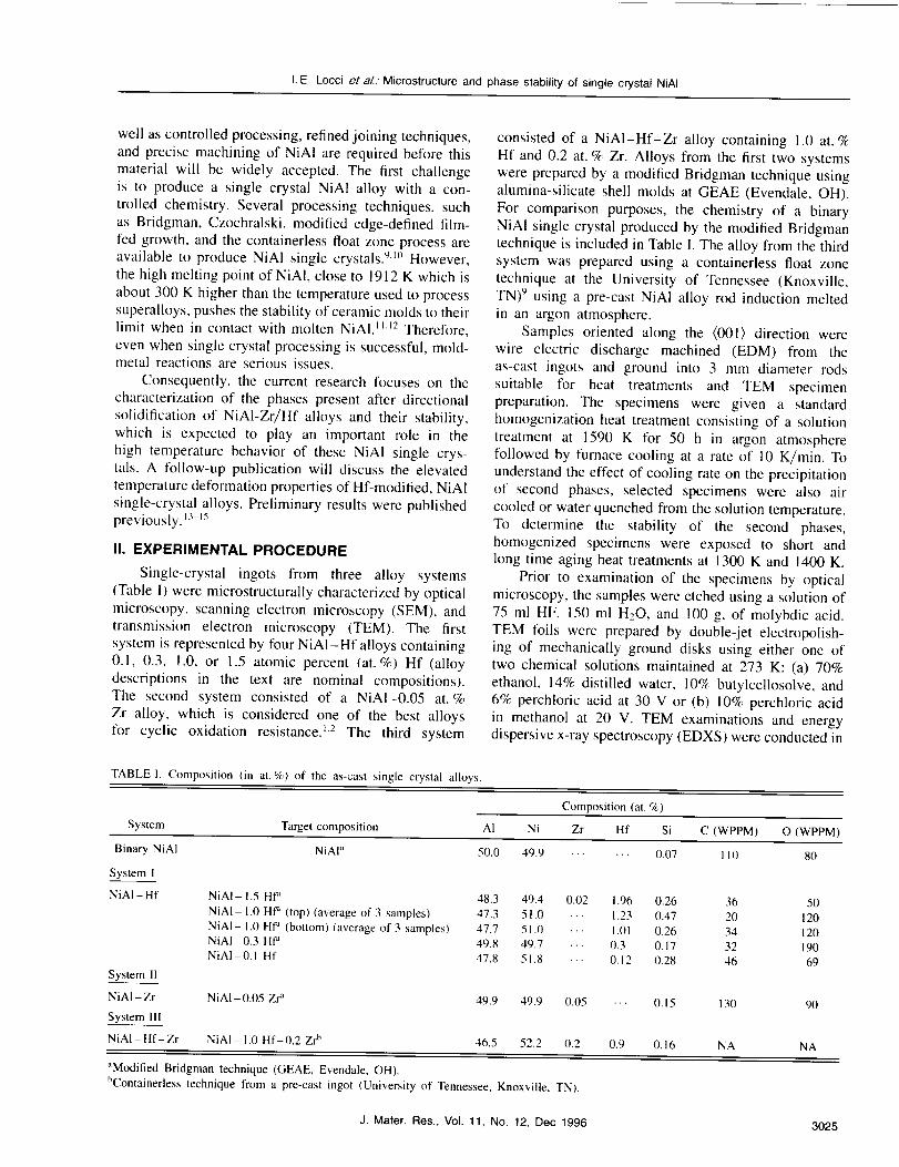
TABLEI. Composition (in at.%) of the as-cast single crystal alloys.
consisted of a NiAI-Hf-Zr alloy containing 1.0 at. %Hf and 0.2 at. % Zr. Alloys from the first two systemswere prepared by a modified Bridgman technique usingalumina-silicate shell molds at GEAE (Evendale, OH).
For comparison purposes, the chemistry of a binaryNiAl single crystal produced by the modified Bridgmantechnique is included in Table I. The alloy from the thirdsystem was prepared using a containerless float zone
technique at the University of Tennessee (Knoxville,TN) 9 using a pre-cast NiAI alloy rod induction meltedin an argon atmosphere.
Samples oriented along the (0011 direction werewire electric discharge machined (EDM) from theas-cast ingots and ground into 3 mm diameter rods
suitable for heat treatments and TEM specimenpreparation. The specimens were given a standardhomogenization heat treatment consisting of a solution
treatment at 1590 K for 50 h in argon atmospherefollowed by furnace cooling at a rate of 10 K/rain. Tounderstand the effect of cooling rate on the precipitationof second phases, selected specimens were also air
cooled or water quenched from the solution temperature.To determine the stability of the second phases,homogenized specimens were exposed to short andlong time aging heat treatments at 1300 K and 1400 K.
Prior to examination of the specimens by opticalmicroscopy, the samples were etched using a solution of
75 ml HF, 150 ml H20, and 100 g, of molybdic acid.TEM ['oils were prepared by double-jet electropolish-ing of mechanically ground disks using either one oftwo chemical solutions maintained at 273 K: (a) 70%ethanol, 14% distilled water, 10% butylcellosolve, and6% perchloric acid at 30 V or (b) 10% perchloric acidin methanol at 20 V. TEM examinations and energydispersive x-ray spectroscopy (EDXS) were conducted in
System Targetcomposition AI
Composition(at, %)
Ni Zr Hf Si C (WPPM) O (WPPM)Binary NiAl
System I
NiAI-Hf
System 1]
NiAI- Zr
System Ill
NiAI" 50.0 49.9 ...... 0.07 110 80
NiAI- 1.5 Hfa 48.3 49.4 0.02 1.96 0.26NiAI- 1,0 HP (top) (averageof 3 samples) 47.3 51,0 •.. 1.23 0,47NiAI- 1,0 Hf" (bottom) (averageof 3 samples) 47.7 51.0 ... 1,01 0.26NiAI- 0.3 Hfd 49.8 49.7 ... 0.3 0,17NiAI- 0.1 Hf 47,8 51.8 ... 0.12 0.28
NiAI- 0.05 Zra 49.9 49.9 0.05 ... 0.15
NiAI-Hf-Zr NiAI-1,0 Hf-0.2 Zr_ 46.5 52.2 0.2 0.9 0.16
36 5020 12034 12032 19046 69
13(1 90
NA NA
_ModifiedBridgman technique(GEAE, Evendale, OH).bContainerlesstechnique from a pre-cast ingot (Universityof Tennessee, Knoxville,TN).
J. Mater.Res.,Vol. 11, No. 12, Dec 1996 3025
I.E. Locci et a/.: Microstructure and phase stability of single crystal NiAI
(a)
(c)
• °
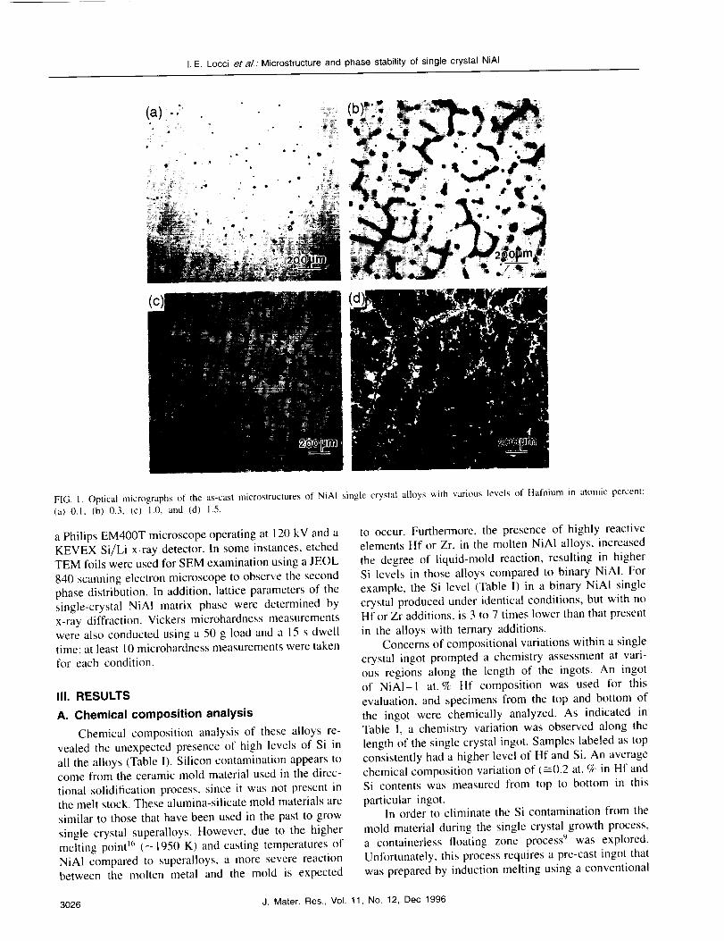
FIG. 1. Optical micrographs of the as-cast microstructures of NiAI single crystal alloys with various levels of Hafnium in atomic percent:(a) 0.1, (b) 0.3, (c) 1.0, and (d) 1.5.
a Philips EM400T microscope operating at 120 kV and a
KEVEX Si/Li x-ray detector. In some instances, etchedTEM foils were used for SEM examination using a JEOL
840 scanning electron microscope to observe the second
phase distribution. In addition, lattice parameters of the
single-crystal NiAI matrix phase were determined by
x-ray diffraction. Vickers microhardness measurementswere also conducted using a 50 g load and a 15 s dwell
time; at least 10 microhardness measurements were takenfor each condition.
III. RESULTS
A. Chemical composition analysis
Chemical composition analysis of these alloys re-
vealed the unexpected presence of high levels of Si in
all the alloys (Table I). Silicon contamination appears tocome from the ceramic mold material used in the direc-
tional solidification process, since it was not present inthe melt stock. These alumina-silicate mold materials are
similar to those that have been used in the past to grow
single crystal superalloys. However, due to the higher
melting point _6 (--1950 K) and casting temperatures of
NiA1 compared to superalloys, a more severe reactionbetween the molten metal and the mold is expected
to occur. Furthermore, the presence of highly reactiveelements Hf or Zr, in the molten NiAI alloys, increased
the degree of liquid-mold reaction, resulting in higher
Si levels in those alloys compared to binary NiAI. For
example, the Si level (Table I) in a binary NiAI single
crystal produced under identical conditions, but with noHf or Zr additions, is 3 to 7 times lower than that present
in the alloys with ternary additions.Concerns of compositional variations within a single
crystal ingot prompted a chemistry assessment at vari-
ous regions along the length of the ingots. An ingotof NiAI-I at.% Hf composition was used for this
evaluation, and specimens from the top and bottom of
the ingot were chemically analyzed. As indicated inTable I, a chemistry variation was observed along the
length of the single crystal ingot. Samples labeled as top
consistently had a higher level of Hf and Si. An averagechemical composition variation of (_0.2 at. % in Hf andSi contents was measured from top to bottom in this
particular ingot.In order to eliminate the Si contamination from the
mold material during the single crystal growth process,a containerless floating zone process 9 was explored.
Unfortunately, this process requires a pre-cast ingot that
was prepared by induction melting using a conventional
3026 J. Mater. Res., Vol. 11, No. 12, Dec 1996
I.E.Loccieta/.." Microstructure and phase stability of single crystal NiAI
mold that also contained Si as one of the mold additives.
The resultant Si content in the system III alloy (Table I)
turned out to be similar to that measured in alloys
processed by the Bridgman melt processing technique.
Moreover, the starting Hf stock material used in the
initial processing of this system contained some Zr as an
impurity, and thus Zr was also introduced in the alloy
during the initial induction melting process.
B. Microstructure of as-cast and
homogenized alloys
The microstructures of three NiA1 single crystalalloy systems were studied in order to understand
the effect of ternary additions on NiAI single crystals
after exposure at high temperatures. Detailed study wasconducted on the alloys containing Hf alone (system I);although, as described in this section, both common and
unique microstructural features were found in all three
systems.
1. System I: NiAI-Hf alloys
As-cast microstructures
In this system, four single crystal NiAI alloys con-
taining Hf levels of 0.1, 0.3, 1.0, and 1.5 (at. %) were
investigated in detail. The optical micrographs of the as-
cast microstructures for these alloys are shown in Fig. 1.Hafnium-rich particles and interdendritic regions, identi-
fied in the SEM, were observed in all the as-cast alloys at
levels proportional to the Hf content. Figure l(a) shows
that as little as 0.1 at. % Hf produced Hf-rich regions.Alloys with higher levels of hafnium (i.e., 0.3, 1.0, or
1.5 at. % Hf) clearly showed the interdendritic nature of
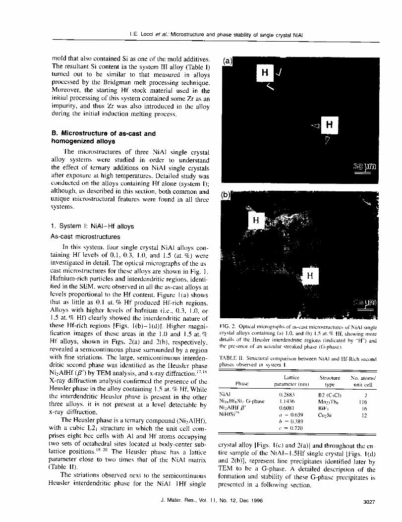
these Hf-rich regions [Figs. l(b)-l(d)]. Higher magni-
fication images of these areas in the 1.0 and 1.5 at. %
Hf alloys, shown in Figs. 2(a) and 2(b), respectively,
revealed a semicontinuous phase surrounded by a regionwith fine striations. The large, semicontinuous interden-
dritic second phase was identified as the Heusler phase
NizAIHf (/3') by TEM analysis, and x-ray diffraction. 17,Is
X-ray diffraction analysis confirmed the presence of the
Heusler phase in the alloy containing 1.5 at. % Hf. While
the interdendritic Heusler phase is present in the other
three alloys, it is not present at a level detectable byx-ray diffraction.
The Heusler phase is a ternary compound (Ni2AIHD,with a cubic L2t structure in which the unit cell com-
prises eight bcc cells with AI and Hf atoms occupyingtwo sets of octahedra[ sites located at body-center sub-
lattice positions. 18-2° The Heusler phase has a latticeparameter close to two times that of the NiAI matrix(Table II).
The striations observed next to the semicontinuous
Heusler interdendritic phase for the NiAI-IHf single
FIG. 2. Optical micrographs of as-cast microstructures of NiAI singlecrystal alloys containing (a) 1.0, and (b) 1.5 at. % HI', showing moredetails of the Heusler interdendritic regions (indicated by "H") andthe presence of an acicular streaked phase (G-phase).
TABLE 11. Structural comparison between NiAI and Hf-Rich secondphases observed in system 1.
Lattice Structure No. atoms/Phase parameter (nm) type unit cell
NiAI 0.2883 B2 (CsCI) 2Nil_,Hf6Si7G-phase l. 1436 Mn23Th6 116Ni2AIHf/T 0.6081 BiF3 16NiHfSi25 a = 0.639 Co2Si 12
b = 0.389c = 0.720
crystal alloy [Figs. l(c) and 2(a)] and throughout the en-
tire sample of the NiAI-1.5Hf single crystal [Figs. l(d)
and 2(b)], represent fine precipitates identified later by
TEM to be a G-phase. A detailed description of the
formation and stability of these G-phase precipitates ispresented in a following section.
J. Mater. Res., Vol. 11, No. 12, Dec 1996 3027
I.E.Locciet aL: Microstructure and phase stability of single crystal NiAI
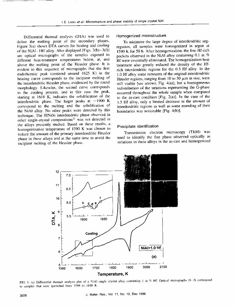
Differential thermal analysis (DTA) was used to
define the melting point of the secondary phases.
Figure 3(a) shows DTA curves for heating and cooling
of the NiAI-lHf alloy. Also displayed [Figs. 3(b)-3(f)]
are optical micrographs of the samples exposed todifferent heat-treatment temperatures below, at, and
above the melting point of the Heusler phase. It isevident in this sequence of micrographs that the first
endothermic peak (centered around 1625 K) in the
heating curve corresponds to the incipient melting ofthe interdendritic Heusler phase, evidenced by the round
morphology. Likewise, the second curve correspondsto the cooling process, and in this case the peak,
starting at 1618 K, indicates the solidification of theinterdendritic phase. The larger peaks at -1900 K
correspond to the melting and the solidification of
the NiAI alloy. No other peaks were detected by this
technique. The HfNiSi interdendritic phase observed inother single-crystal compositions 2_ was not detected in
the alloys presently studied. Based on these results, a
homogenization temperature of 1590 K was chosen toreduce the amount of the primary interdendritic Heusler
phase in these alloys and at the same time to avoid the
incipient melting of the Heusler phase.
Homogenized microstructure
To minimize the large degree of interdendritic seg-
regation, all samples were homogenized in argon at1590 K for 50 h. After homogenization, the fine Hf-rich
pockets observed in the NiAI alloy containing 0.1 at. %Hf were essentially eliminated. The homogenization heat
treatment also greatly reduced the density of the Hf-
rich interdendritic regions for the 0.3 Hf alloy. In the
1.0 Hf alloy some remnants of the original interdendritic
Heusler regions, ranging from 10 to 30 pm in size, werestill visible [see arrows, Fig. 4(a)], but a homogeneousredistribution of the striations representing the G-phase
occurred throughout the whole sample when compared
to the as-cast condition [Fig. 2(a)]. In the case of the
1.5 Hf alloy, only a limited decrease in the amount of
interdendritic regions as well as some rounding of theirboundaries was noticeable [Fig. 4(b)].
Precipitate identification
Transmission electron microscopy (TEM) was
used to identify the fine phase observed optically asstriations in these alloys in the as-cast and homogenized
I--a
127.0
11
51500
10
Cooling
I NiAI+I.0 Hf I
(a)
1600 1700 1800 1900 2000 2100
Temperature, K
FIG. 3. (a) Differential thermal analysis plot of a NiA1 single crystal alloy containing 1 at. % Hf. Optical micrographs (b-f) correspondto samples that were quenched from 1598 to 1648 K.
3028 J. Mater. Res., Vol. 11, No. 12, Dec 1996

I.E. Locci e! aL. Microstructure and phase stability of single crystal NiAI
(a)
(b)
FIG. 4. Optical microstructure of NiAI single crystal alloys contain-
ing (a) 1.0 and (b) 1.5 at. % Hf after the standard homogenization heat
treatment, 1590 K for 50 h followed by furnace cooling ( 10 K/rain).
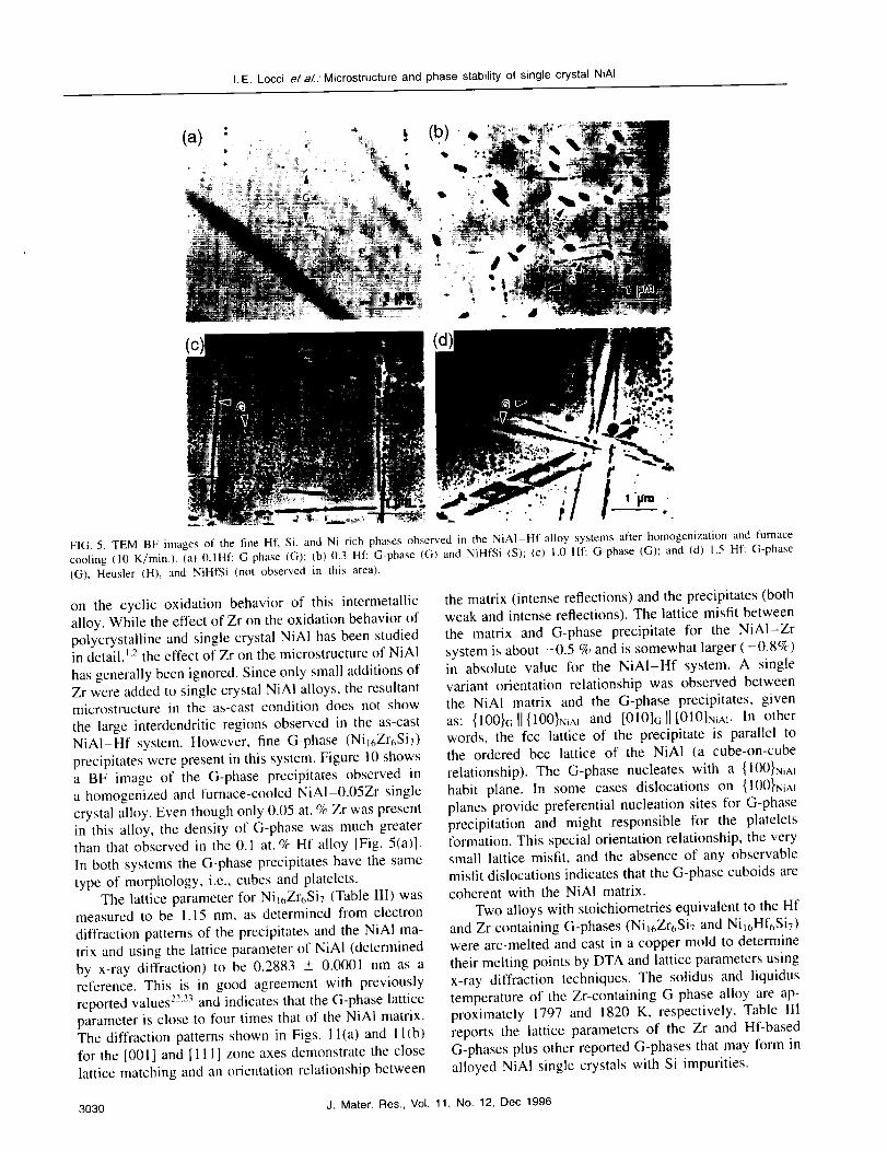
conditions. Figure 5 shows bright-field (BF) images
of the fine phases observed in the NiAI-Hf alloy
system after homogenization and furnace cooling (10K/min). Contrary to what was expected based on the
phase diagram, 18 the precipitates were not the expectedHeusler (Ni2AIHf) phase, but instead were found to be
rich in Ni, Hf, and Si using EDXS. Because of the prox-
imity of the Si K,_ (1.74 keV) and HfM,_ (1.645 keV)energy peaks, final confirmation of the presence of Si
in these precipitates was accomplished by observations
of the same type of precipitates in the NiAI-0.05Zr
alloy where no energy peaks overlap exits betweenthe Zr and Si. Most precipitates were identified as
G-phase (Ni16Hf65i7)13,22,23; however, in some instances
a NiHfSi phase [large dark phase shown in Fig. 5(b)]
was also observed. As reported earlier, 14,15,24substantialSi, available from the shell mold, has dissolved in the
molten metal alloy, resulting in the formation of the fine
G-phase or NiHfSi precipitates during solidification and
after heat treatments. Figures 6(a) and 6(b) show themorphology of the G-phase observed in the NiAI-IHf
alloy after homogenization and furnace cooling. Under
the conditions shown in Fig. 6, elongated platelets andsmall cuboidal G-phase precipitates can be observed. The
platelet precipitates are associated with denuded regions,as clearly observed in Fig. 6(b) where the TEM foil
was tilted by --45 ° with respect to the image shown in
Fig. 6(a). The platelets range l_om 0.1 to 1 #m in length.The finer precipitates, ranging from 5 to 20 nm, are
cuboidal in shape as shown in the dark-field (DF) image(Fig. 7), where two faces and one edge of the individual
cubes are visible. A corresponding diffraction patternshown in Fig. 7 is close to the [011] zone axis. These
same precipitates existed in the as-cast condition; how-
ever, their density varied from region to region due to the
inhomogeneous interdendritic segregation [see Fig. l(c]).These G-phase precipitates were also observed in the 0.1
and 0.3 Hf alloys, although at a reduced density (Fig. 5).
In addition to the G-phase, the NiHfSi phase wasmainly observed in the NiAI alloy containing 0.3 HI"
[Figs. 5(b) and 8]. The crystallography of the NiHfSi
phase has been described in detail by Garg et al. 24
The NiHfSi phase has an orthorhombic structure, and
its lattice parameters are reported in Table IIY Micro-
diffraction patterns corresponding to the [ 121 ]NiHf:Siand
[I 31 ]NiHfSizone axes are shown in Fig. 8. The finer cubesand platelets of G-phase can also be observed in the
background of Fig. 8. The NiHfSi precipitates are about
0.25 Izm in length as compared to the G-phase, which
is about 10 nm in size. This phase was nonuniformly
distributed in the NiAI-0.3Hf alloy, and its presencevaried substantially from specimen to specimen.
Homogenization and furnace cooling of the highestHf-containing NiA1 alloy (NiAI-I.5Hf) also resulted
in the presence of discontinuous G-phase platelets and
cubic precipitates (Fig. 9). Occasionally, the NiHfSi
phase was also observed; however, the precipitate den-
sity was very low and inhomogeneously distributed. Inaddition, small Heusler precipitates of size 250 nm or
less were also detected in this alloy. Table II summarizes
the structure and lattice parameters of all three types
of precipitates detected in the NiAI-Hf system andcompares them to NiA1.
2. System I1: NiAI-Zr alloy
In the early stages of NiA1 alloy development, Zrwas a common addition because of its beneficial effect
J. Mater. Res., Vol. 11, No. 12, Dec 1996 3029
I.E. Locci et aL.' Microstructure and phase stability of single crystal NiAI
(a)
(c)
l"
"" i I
FIG. 5. TEM BF images of the fine Hf, Si, and Ni rich phases observed in the NiAI-Hf alloy systems after homogenization and furnace
cooling (10 K/min.). (a) 0.1Hf: G-phase (G); (b) 0.3 Hf: G-phase (G) and NiHfSi (S); (c) 1.0 Hf: G-phase (G); and (d) 1.5 Hf: G-phase
(G), Heusler (HI}, and NiHfSi (not observed in this area).
on the cyclic oxidation behavior of this intermetallic
alloy. While the effect of Zr on the oxidation behavior of
polycrystalline and single crystal NiAI has been studiedin detail, _'2the effect of Zr on the microstructure of NiAI
has generally been ignored. Since only small additions ofZr were added to single crystal NiAI alloys, the resultantmicrostructure in the as-cast condition does not show
the large interdendritic regions observed in the as-castNiAI-Hf system. However, fine G-phase (Nil6Zr6SiT)
precipitates were present in this system. Figure 10 showsa BF image of the G-phase precipitates observed in
a homogenized and furnace-cooled NiA1-0.05Zr single
crystal alloy. Even though only 0.05 at. % Zr was presentin this alloy, the density of G-phase was much greaterthan that observed in the 0.1 at. % Hf alloy [Fig. 5(a)].
In both systems the G-phase precipitates have the same
type of morphology, i.e., cubes and platelets.The lattice parameter for Ni16Zr6Si7 (Table III) was
measured to be 1.15 nm, as determined from electron
diffraction patterns of the precipitates and the NiA1 ma-
trix and using the lattice parameter of NiAI (determined
by x-ray diffraction) to be 0.2883 +- 0.0001 nm as areference. This is in good agreement with previously
reported values 22'23 and indicates that the G-phase lattice
parameter is close to four times that of the NiAI matrix.The diffraction patterns shown in Figs. I l(a) and 1 l(b)
for the [001 ] and [11 I ] zone axes demonstrate the close
lattice matching and an orientation relationship between
the matrix (intense reflections) and the precipitates (both
weak and intense reflections). The lattice misfit between
the matrix and G-phase precipitate for the NiA1-Zr
system is about -0.5 % and is somewhat larger (-0.8%)in absolute value for the NiAI-Hf system. A single
variant orientation relationship was observed between
the NiAI matrix and the G-phase precipitates, given
as: {100}G]I{100}NiAI and [010]G]I[010]NiA1- In otherwords, the fcc lattice of the precipitate is parallel to
the ordered bcc lattice of the NiAI (a cube-on-cube
relationship). The G-phase nucleates with a {100}NiAI
habit plane. In some cases dislocations on {100}NiAI
planes provide preferential nucleation sites for G-phase
precipitation and might responsible for the plateletsformation. This special orientation relationship, the verysmall lattice misfit, and the absence of any observable
misfit dislocations indicates that the G-phase cuboids are
coherent with the NiA! matrix.
Two alloys with stoichiometries equivalent to the Hf
and Zr containing G-phases (Nil6Zr6Si7 and Ni16Hf6Siv)were arc-melted and cast in a copper mold to determine
their melting points by DTA and lattice parameters using
x-ray diffraction techniques. The solidus and liquidus
temperature of the Zr-containing G-phase alloy are ap-
proximately 1797 and 1820 K, respectively. Table IIlreports the lattice parameters of the Zr and Hf-based
G-phases plus other reported G-phases that may form in
alloyed NiAI single crystals with Si impurities.
3030 J. Mater. Res., Vol. 11, No. 12, Dec 1996

I.E. Locci el a/.. Microstructure and phase stability of single crystal NiAI
FIG. 7. TEM DF image ofcuboidal Ni]6Hf6Si7 (G-phase) precipitatesimaged close to the [01 I J zone axis in a NiAI- 1Hf single crystal alloyshowing cube faces viewed edge-on.
."(b).....
B
FIG. 6. (a) TEM BF image of Nil6Hf6Si7 (G-phase) platelet andcuboidal precipitates observed in a single crystal NiAI-I at. % Hf
specimen annealed at 1590 K for 50 h and furnace cooled. (b) TEM
BF image of the same area, but foil was tilted by 45 ° with respect tothe position shown in Fig. 6(a).
'; %,,
FIG. 8. TEM BF image showing the NiHfSi phase (larger parallepi-
ded shaped particles) observed in the NiAI-0.3 at. % Hf alloy after
homogenization and furnace cooling. In the background G-phasecubes and platelets (Ni_6Hf_Si7) are also imaged. Microdiffraction
patterns corresponding to 11211 and I131] zone axes of the NiHfSiphase are also shown.
3. System II1: NiAI-Hf-Zr alloy
This system was studied to investigate the resultant
microstructure when Hf and Zr are both present in a
single crystal alloy. The ingot produced by this techniquehad a large amount of interdendritic segregation, similar
in microstructure to the NiAI-IHf alloy. The microstruc-
ture was examined in detail after the homogenization
and furnace cooling treatment given to all the alloys.
As shown in Fig. 12(a), this treatment resulted not onlyin the formation of G-phase (10 to 40 nm cubes and
0.25 to 3.5 /zm platelets), but also in the formation of
some Heusler precipitates (50 to 150 nm in diameter).This combination of precipitates was not observed in the
alloys containing low levels of Hf (0.1 to 1 Hf) or Zrafter the original homogenization treatment. The Heusler
J. Mater. Res., Vol. 11, No. 12, Dec 1996 3031
I.E.Locciet aL. Microstructure and phase stability of single crystal NiAI
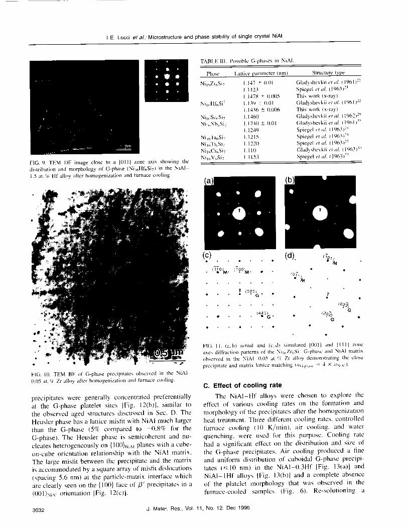
FIG. 9. TEM DF image close to a 10111 zone axis showing the
distribution and morphology of G-phase (Nile, Hf6SiT) in the NiA1
1.5 at. c/,. HI alloy after homogenization and furnace cooling.
TABLE 111. Possible G-phases in NiAI.
Phase Lattice parameter (nm Structure type
Niv, Zr¢,Si7 I. 147 + 0.01 Gladyshcvkii eta/. ( 1961 )2_
1.1423 Spiegel eta/. (19631 >
I. 1478 + 0.(X}5 This work (x-ray)
NiI_,HI'_,Si7 1.139 + 0.0[ Gladyshevkii et al. ([961)2_,
1.1436 -+ 0.006 This work (x-ray)
Niu, Sc_,Si7 1.1460 Gladyshevkii et al. (1962) >
Nil_,Nb¢,Si7 1.1240 +- 0.01 Gladyshevkii et a/. (1961 )271.1249 Spiegel et al. (1963) >
Ni v, Ta_Si7 I. 1215 Spiegel eta/. ( 1963)>
Ni i_,Tb,Si7 I. 1220 Spiegel et al. (1%3) >
Nil_,Cr_,Si7 I. 110 Gladyshevkii et al. ( 1963 )>
NiI_,V_Si7 1.1153 Spiegel et al. t 1963t >
FIG. 10. TEM BF of G-phase precipitates obscrved in the NiAI
0.05 at. % Zr alloy after homogenization and furnace cooling.
precipitates were generally concentrated preferentiallyat the G-phase platelet sites IFig. 12(b)], similar tothe observed aged structures discussed in Sec. D. TheHeusler phase has a lattice misfit with NiAI much largerthan the G-phase (5% compared to -0.8% for the
G-phase). The Heusler phase is semicoherent and nu-cleates heterogeneously on {l()0}y_Aiplanes with a cube-on-cube orientation relationship with the NiAI matrix.The large misfit between the precipitate and the matrixis accommodated by a square array of misfit dish)cations(spacing 5.6 nm) at the particle-matrix interface whichare clearly seen on the {100} face of/3' precipitates in a(00I}NiAI orientation [Fig. 12(c)1.
(c). . . (d). n'o,,_
i_ol M. iToolM. , _ •
f (o2o_. • r• •
• . I_,o_G. . {2.o_jG
co?_jG
FIG. II. (a,b) actual and (c,d) simulated IO01l and I1111 zone
axes diffruction palterns of the Nil(_Zr(,Si7 G-phase and NiAI matrixobserved in the NiA1 0.05 at. _,:_,Zr alloy demonstrating the close
precipitate and matrix lattice matching (a(; ph_,_.= 4 × ax,.v ).
C. Effect of cooling rate
The NiAI-Hf alloys were chosen to explore theeffect of various cooling rates on the formation andmorphology of the precipitates alter the homogenizationheat treatment. Three different cooling rates, controlled
furnace cooling (10 K/rain), air cooling, and waterquenching, were used for this purpose. Cooling ratehad a significant effect on the distribution and size ofthe G-phase precipitates. Air cooling produced a lineand uniform distribution of cuboidal G-phase precipi-
tates (<_10 nm) in the NiA1-0.3Hf [Fig. 13(a)l andNiAI-IHf alloys IFig. 13(b)] and a complete absenceof the platelet morphology that was observed in thefurnace-cooled samples (Fig. 6). Re-solutioning a
3032 J. Mater. Res., Vol. 11, No. 12, Dec 1996

I.E. Locci e! a/.. Microstructure and phase stability of single crystal NiAI
(a)
FIG. 12. (a) TEM BF images of G-phase and Heusler precipitates observed in the NiAI-Hf-Zr alloy after the standard homogenization heattreatment followed by furnace cooling. (b) Higher magnification showing that the Heusler phase forms preferentially at the G-phase plateletsites. (c) A square network of misfit dislocations observed at the Heusler particle-matrix interface close to (001)SiAl zone axis.
homogenized and furnace-cooled NiAi-IHf sample
by reheating to 1590 K for only 20 min, followed byair cooling, produced a microstructure similar to that
shown in Fig. [3(b), indicating that the dissolution of
the G-phase, both platelets and cuboids, occurs rapidly.
Air cooling completely eliminated the G-phase
platelets and the NiHfSi phase that were previously
observed in the NiAI-0.3Hf alloy after furnace cooling
(Fig. 8). Moreover, faster cooling rates, such as waterquenching, completely suppressed the formation of
the G-phase, resulting in a single phase B2 NiAIwith no second phases, other than the interdendritic
regions. These observations indicate that the G-phaseprecipitates completely dissolve at 1590 K and then may
reprecipitate during cooldown. The cooling rates control
the formation, size, morphology, and distribution of the
G-phase precipitates, suggesting that these characteristics
can be optimized through proper control.
D. Aging studies: Stability of secondary phases
1. System I: NiAI-Hf alloys
Figure 14 shows the microstructures observed in the
homogenized and air cooled NiA1-1Hf alloy after aging
samples at 1300 K for I, 100, and 500 h. Figure 14(a)
shows the presence of an additional phase that appears
after only 1 h of aging and continues to grow with aging
time. A microdiffraction pattern along the [001] zone
axis from one of the larger precipitates in Fig. 14(c)
identifies these precipitates as the expected Heusler
phase. In the background, the finer G-phase precipitates
can be clearly seen after 1 b of aging [Fig. 14(a)].
Denuded regions are always associated with the largerHeusler particles. This is an indication that someG-phase precipitates have dissolved in favor of the
Heusler precipitates. At an intermediate aging time
of 100 h the Heusler precipitates coalesced into a
"worm-like" morphology, while the density of G-phase
precipitates was reduced further [Fig. 14(b)]. After
500 h, larger and more equiaxed Heusler precipitates
were formed [Fig. 14(c)] and very few G-phase precipi-
tates were visible. In contrast to the Heusler particles
that coarsened as a function of time, the G-phase didnot coarsen appreciably. Instead, the G-phase particles
appeared to dissolve in favor of the ill-precipitates.
Aging the NiAI-1Hf alloy at 1300 K for 1 h
after homogenization and furnace cooling also resulted
in the formation of /31 precipitates, but in this case,
they preferentially nucleated at the G-phase platelet
sites, as shown in Fig. 15. Again, misfit dislocationsat the precipitate-matrix interface are visible. The
G-phase platelets seem to be heterogeneous nucleationsites for the Heusler precipitate formation. This was also
the case for the homogenized NiAI-Hf-Zr alloy shownin Fig. 12.
Microhardness values and Heusler precipitate sizes
for various cooling rate conditions and different stages of
aging at 1300 K are summarized in Fig. 16. The highest
J. Mater. Res., Vol. 11, No. 12, Dec 1996 3033

I.E.Loccie/a/.. Microstructure and phase stability of single crystal NiAI
(a)i°
FIG. 13. TEM BF images of G-phase precipitates observed in the(a) NiA1-0.3 at.% Hf and (b) NiAI-I.0 at. % Hf alloys alter thestandard homogenization heat treatment followed by air cooling. Onlyfiner G-phase cubes formed under this condition.
hardness values correspond to the NiA1-lHf alloy (theNiAI-1.5Hf was not examined) in either the air-cooled
or water-quenched condition. In the air-cooled sample,
Heusler precipitates were not present and G-phase pre-
cipitates were cuboidal in shape and homogeneouslydistributed in the matrix (Fig. 13), whereas no precipi-
tates were detectable by TEM after water quenching.
Furnace cooling, which produced a mixed distribution
of cuboidal G-precipitates and platelets (Fig. 6), shows
a lower microhardness value than the air cooled or
water-quenched conditions. Microhardness values pro-gressively decreased as a function of 1300 K agingtime. Microhardness values for the NiAL alloys contain-
ing 0.3 and 0.1 at.% Hf in the as-homogenized andfurnace-cooled condition are also included in Fig. 16.
As expected, lower additions of Hf resulted in lowermicrohardness values.
Aging the NiAI-1Hf alloy at 1400 K for 20 h afterthe standard homogenization heat treatment resulted in
the formation of /3 _ Heusler precipitates and complete
dissolution of the G-phase precipitates. Figure 17(a)
corresponds to a region where Heusler probably formed
at the expense of the original G-phase platelets, since
the spacing between the rows of Heusler precipitates
corresponds approximately to the spacing between the
G-phase platelets prior to the aging heat treatment.In contrast, long-term aging of the NiAI-O.3Hf alloy
at 1300 K for 168 h after homogenization and furnace
cooling (condition shown in Fig. 8), resulted in the
complete dissolution of the G-phase with only NiHfSi
precipitates remaining [Fig. 17(b)]. No /3 _ precipitates
were observed in the regions analyzed.
2. System I1: NiAI-Zr alloy
Aging of the homogenized and furnace-cooledNiAI-0.05 at.% Zr alloy at 1300 K ['or 168 h resulted
in the formation of the NiZrSi phase and the complete
dissolution of the G-phase precipitates as shown in
Fig. 17(c). Similar to the NiHfSi phase, observed insome of the NiAI-Hf alloys, NiZrSi has an orthorhombic
structure with lattice parameters, a = 0.647 nm, b =0.3815, and c = 0.7263 nm. 2_
3. System II1: NiAI-Hf-Zr alloy
Aging of the homogenized and furnace-cooledNiAI-IHf-0.2Zr alloy at 1300 K for only 1 h resulted
in the complete dissolution of the G-phase, with only
aligned /3 _ Heusler precipitates left, as shown in
Fig. 17(d).
IV. DISCUSSION
Microstructural characterization of single crystal
NiA1 alloys with reactive element additions of Hf and
Zr was carried out using different degrees of resolution.
Optical and SEM techniques were useful in imagingand analyzing the larger regions of interdendritic
segregation present in these systems, whereas TEM
was required to resolve and ascertain the finer phases
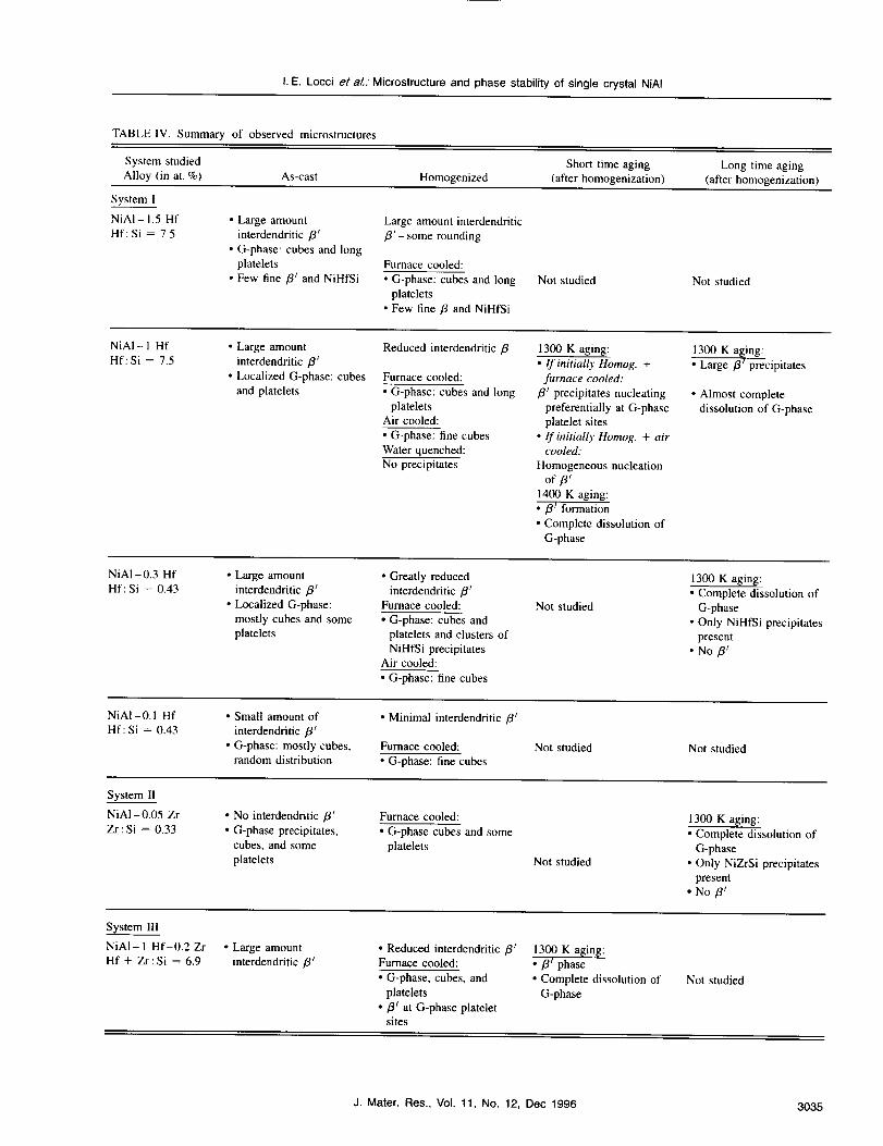
formed during the various heat treatments. All theseresults are summarized in Table IV. As expected, the
amount of interdendritic segregation after directional
solidification was proportional to the level of alloying
3034 J. Mater. Res., Vol. 11, No. 12, Dec 1996
I.E. Locci et aL. Microstructure and phase stability of single crystal NiAI
TABLE IV. Summary of observed microstructures.
System studied Short time aging Long time aging
Alloy (in at. %) As-cast Homogenized (after homogenization) (after homogenization)
System I
NiAI-I.5 Hf
Hf: Si = 7.5
• Large amount
interdendritic /3 r
• G-phase: cubes and long
platelets
• Few fine /3 _ and NiHfSi
Large amount interdendritic
fll _ some rounding
Furnace cooled:
• G-phase: cubes and long
platelets
• Few fine/3 and NiHfSi
Not studied Not studied
NiAI - 1 Hf
Hf: Si = 7.5• Large amount
interdendritic/3 /
• Localized G-phase: cubes
and platelets
Reduced interdendritic/3
Furnace cooled:
• G-phase: cubes and long
platelets
Air cooled:
• G-phase: fine cubes
Water quenched:
No precipitates
1300 K aging:
• If initially Homog. +
furnace cooled:
/3/ precipitates nucleating
preferentially at G-phase
platelet sites
• If initiaUy Homog. + air
cooled:
Homogeneous nucleation
of/31
1400 K aging:
•/3/ formation
• Complete dissolution of
G-phase
1300 K aging:
• Large fll precipitates
• Almost complete
dissolution of G-phase
NiA1-0.3 Hf
Hf:Si = 0.43• Large amount
interdendritic/3/
• Localized G-phase:
mostly cubes and some
platelets
• Greatly reduced
interdendritic/3_Furnace cooled:
• G-phase: cubes and
platelets and clusters of
NiHfSi precipitatesAir cooled:
• G-phase: fine cubes
Not studied
1300 K aging:
• Complete dissolution of
G-phase
• Only NiHfSi precipitates
present
• No /3/
NiAI-0.1 Hf
Hf: Si = 0.43
• Small amount of
interdendritic /3/
• G-phase: mostly cubes,
random distribution
• Minimal interdendritic /3/
Furnace cooled:
• G-phase: fine cubes
Not studied Not studied
System II
NiA1-0.05 Zr
Zr:Si=0.33• No interdendritic/3 _
• G-phase precipitates,
cubes, and some
platelets
Furnace cooled:
• G-phase cubes and some
platelets
Not studied
1300 K aging:
• Complete dissolution of
G-phase
• Only NiZrSi precipitates
present
• No fl I
System 111
NiA1-1 Hf-0.2 Zr
Hf + Zr:Si = 6.9• Large amount
interdendritic fl/
• Reduced interdendritic/3tFurnace cooled:
• G-phase, cubes, and
platelets
•/3 ! at G-phase platelet
sites
1300 K aging:
• /31 phase
• Complete dissolution of
G-phase
Not studied
J. Mater. Res., Vol. 11, No. 12, Dec 1996 3035
I.E. Locci et aL." Microstructure and phase stability of single crystal NiAI
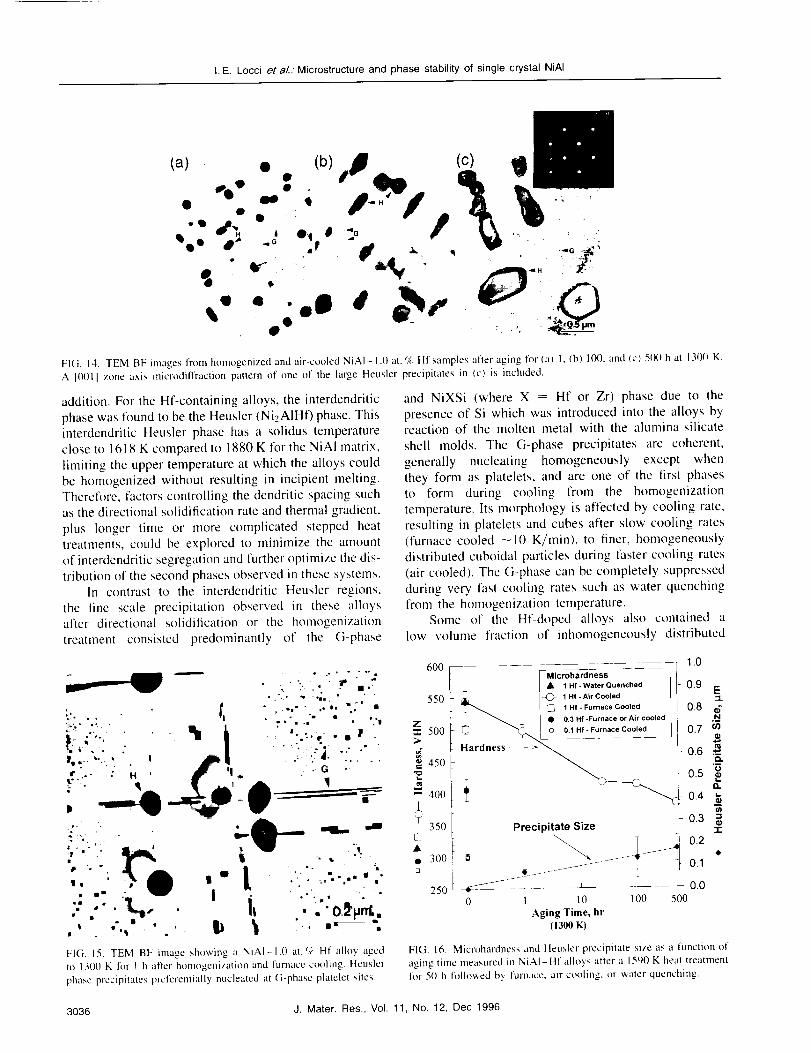
FIG. 14. TEM BF images from homogenized and air-cooled NiAI- 1.0 at. % HI samples after aging for (a) 1, (b) 100, and (c) 500 h at 1300 K.
A [001] zone axis microdiffraction pattern of one of the large Heusler precipitates in (c) is included.
addition. For the Hf-containing alloys, the interdendritic
phase was found to be the Heusler (NieA1Hf) phase• This
interdendritic Heusler phase has a solidus temperature
close to 1618 K compared to 1880 K for the NiA1 matrix,
limiting the upper temperature at which the alloys could
be homogenized without resulting in incipient melting.
Therefore, factors controlling the dendritic spacing such
as the directional solidification rate and thermal gradient,
plus longer time or more complicated stepped heat
treatments, could be explored to minimize the amount
of interdendritic segregation and further optimize the dis-
tribution of the second phases observed in these systems.
In contrast to the interdendritic Heusler regions,
the fine scale precipitation observed in these alloys
after directional solidification or the homogenization
treatment consisted predominantly of the G-phase
FIG. 15. TEM BF image shmving a NiAI-I.0 at.O} Hf alloy aged
to 1300 K for I h after homogenization and furnace cooling Heusler
phase precipitates preferentially nucleated at G-phase plalelet sites.
and NiXSi (where X = Hf or Zr) phase due to the
presence of Si which was introduced into the alloys by
reaction of the molten metal with the alumina-silicate
shell molds. The G-phase precipitates are coherent,
generally nucleating homogeneously except when
they form as platelets, and are one of the first phases
to form during cooling from the homogenization
temperature. Its morphology is affected by cooling rate,
resulting in platelets and cubes after slow cooling rates
(furnace cooled _10 K/min), to finer, homogeneously
distributed cuboidal particles during faster cooling rates
(air cooled). The G-phase can be completely suppressed
during very fast cooling rates such as water quenching
from the homogenization temperature.
Some of the Hf-doped alloys also contained a
low volume fraction of inhomogeneously distributed
I _Microhardness
t,_, I Hf-Water Quenched
550 _ _ [-'Q)- 1Hf-AirCooled
I _ 1 Hf- Furnace Cooled
[ • 0.3 Hf-Furnace or Air cooled
"I'IZ 500 _ "_,. O [_1 Hf-Furnaca Cooled
>_ Hardness ->
45o f
400
+ i350 Precipitate Size
• k• 300. _ _
1.0
0.9 E=L
i- 0.8 6N
i 0.7 _
.-0.6
0.5 '_
0.4 _
0.3 ='1-
0.2
OA/
250 _4-'_'---- • _ _ _ ___ __L 0.00 I l0 100 500
Aging Time, hr(1300 K)
FIG. 16. Microhardness and Heusler precipitate size as a function of
aging time measured in NiAI-Hf allo3,s after a 1590 K heat treatmentfor 50 h followed by furnace, air cooling, or watcr quenching.
3036 J. Mater. Res., Vol. 11, No. 12, Dec 1996

I.E. Locci et a/.."Microstructure and phase stability of single crystal NiAI
(a)
(c)
FIG. 17. TEM BF images showing (a) only Heusler precipitates in the NiAI-1.0 at. % Hf alloy after an aging heat treatment of 1400 K for20 h with a prior homogenization and furnace-cooled condition. (b) Only NiHfSi precipitates in the NiAI-0.3 Hf alloy aged at 1300 K for168 h. (c) Only NiZrSi precipitates in the NiAI-0.05 Zr alloy aged at 1300 K for 168 h. (d) Only aligned [31Heusler in the NiAI IHf-0.2 Zralloy aged at 1300 K for 1 h after homogenization and furnace cooling.
orthorhombic NiHfSi phase after homogenization. It has
been shown 24 that this precipitate has a {lll}NiAI habit
plane with a rectangular morphology when viewed in its
habit plane. The NiHfSi phase is larger than the G-phase
cubes and closer in size though morphologically distinctfrom the G-platelets. Because it has a much larger
misfit with the NiA! matrix, the presence of this phase
has been attributed to an inhomogeneous nucleationmechanism. 24
Finally, the expected precipitate in these systems,
the Heusler phase, was only marginally observed in thetwo alloys with the highest Hf and Zr levels after the
homogenization treatment. Consequently, cooling fromthe homogenization temperature tended to favor the
nucleation of G-phase with its low misfit or the NiXSi
phase probably due to its unique inhomogeneous nucle-
ation mechanism. 24 Though the aging data in Table IV
are far from complete, it appears that the Heusler phase
was more common after aging at intermediate tempera-tures, indicating that in some, but not all the alloys it
was the thermally stable phase. For example, both the
NiAI-IHf and NiAI-IHf-0.2Zr alloys were partially
or completely composed of Heusler precipitates at the
expense of the original G-phase after long-term aging
treatments. If G-phase platelets are present, nucleation
of Heusler precipitates preferentially occurs at this site,whereas, if only a fine and uniform distribution of
G-phase cubes is present (e.g., air-cooled condition),
then the Heusler phase also precipitates homogeneously.The dissolution of the G-phase precipitates and the
formation and growth of the Heusler precipitates isaccompanied by a reduction in microhardness, and also
was observed to reduce creep life. 15,27 In contrast, the
NiAI-0.05Zr and the NiAI-0.3 Hf alloys consisted
entirely of the NiHfSi phase after long-term aging.In light of the data shown in Table IV, which is
consistent with observations in a companion study on
similar alloys, 28 these observations can be explainedin terms of the reactive element to silicon ratio. In
those alloys where Heusler was stable after aging (seeTable IV), the reactive element to silicon ratio was high
(on the order of 3 to 7), whereas the NiXSi phase was
stable in alloys which had a low reactive element to
silicon ratio (on the order of 0.3 to 1.8). It is likely that
at intermediate values of this ratio, a stable three-phase
alloy composed of NiA1, Heusler, and silicide phasewould likely exist. However, additional work will be
needed to fully understand the effect of small chemical
composition differences, especially Si, on the stability ofthe microstructure in these alloys.
J. Mater. Res., Vol. 11, No. 12, Dec 1996 3037
I.E. Locci eta/.. Microstructure and phase stability of single crystal NiAI
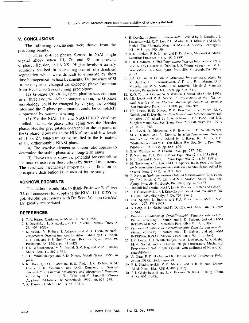
V. CONCLUSIONS
The following conclusions were drawn from the
preceding results:
(1) Three distinct phases formed in NiAI single
crystal alloys when Hf, Zr, and Si are present:
G-phase, Heusler, and NiXSi. Higher levels of ternary
additions resulted in coarse regions of interdendritic
segregation which were difficult to eliminate by short
time homogenization heat treatments. The presence of Si
in these systems changed the expected phase formation
from Heusler to Si-containing precipitates.
(2) G-phase (Nil6X6Siv) precipitation was common
in all three systems. After homogenization, the G-phase
morphology could be changed by varying the cooling
rates and the G-phase precipitation could be completely
suppressed by water quenching.
(3) For the NiAI-IHf and NiAI-IHf-0.2 Zr alloys
studied, the stable phase after aging was the Heusler
phase. Heusler precipitates coarsened at the expense of
the G-phase. However, in the NiAI alloys with low levels
of Hf or Zr, long-term aging resulted in the formation
of the orthorhombic NiXSi phase.
(4) The reactive element to silicon ratio appears to
determine the stable phase after long-term aging.
(5) These results show the potential for controlling
the microstructure of these alloys by thermal treatments.
The resultant mechanical properties as a function of
precipitate distribution is an area of future study.
ACKNOWLEDGMENTS
The authors would like to thank Professor B. Oliver
(U. of Tennessee) for supplying the NiAI- 1Hf-0.2Zr in-
got. Helpful discussions with Dr. Scott Walston (GEAE)
are greatly appreciated.
REFERENCES
1. C.A. Barret, Oxidation of Metals 30, 361 (1988).
2. I. Doychak, J.L. Smialek, and T.E. Mitchell, Metall. Trans. A20, 499 (1989).
3. K. Vedula, V. Pathare, 1. Aslandis, and R.H. Titran, in High-
Temperature Ordered lntermemllic Alloys, edited by C.C. Koch,C.T. Liu, and N.S. Stoloff (Mater. Res. Soc. Syrup. Proc. 39,
Pittsburgh, PA, 1985), pp. 411-421.4. J.D. Whittenberger, M.V. Nathal, S.V. Raj, and V. M. Pathare,
Mater. Lett. II, 267 (1991).
5. I.D. Whittenberger and R.D. Noebe, Metall. Trans. (1995, in
press).6. R. Darolia, D.F. Lahrman, R.D. Field, J.R. Dobbs, K.M.
Chang, E.H. Goldman, and D.G. Konitzer, in Ordered
Intermetallics-Physical Metallurgy and Mechanical Behavior,
edited by C.T. Liu, R.W, Cahn, and G. Sauthoff (KluwerAcademic Publishers, The Netherlands, 1992), pp. 679-698.
7. R. Darolia, J. Metals 43 (3), 44 (1991).
8. R. Darolia, in Structural lntermetallics, edited by R. Darolia, J. J.
Lewansdowski, C.T. Liu, P.L. Marlin, D. B. Miracle, and M. V.
Nathal (The Minerals, Metals & Materials Society, Pennington,
NJ, 1993), pp. 495-504.9, R.D. Reviere, B. F. Oliver, and D, D. Bruns, Materials & Manu-
facturing Processes 4 IlL 103 (1989).10. E, H. Goldman, in High Temperature Ordered hztermemllic Alloys
V, edited by I. Baker, R. Darolia, J. D. Whitteneberger, and M. H.Yoo, (Mater. Res. Soc. Syrup. Proc. 288, Pittsburgh, PA, 1993),
p. 83.11. J.A. Oti and K.O. Yu, in Structural Intermetallics. edited by
R. Darolia, J.J. Lewansdowski, C.T. Liu, P.L. Martin. D.B.
Miracle, and M.V. Nathal (The Minerals, Metals & Materials
Society, Pennington, NJ, 1993), pp. 505-511.12. K, O. Yu, J. A. Oti, and W, S. Walston, J. Metals 45 (5), 49 (1993).
13. I.E. Locci and R,D. Noebe, in Proceedings of the 47th An-
nual Meeting r( the Electron Microscopy Society of America
(San Francisco Press, Inc., 1989), pp. 308-309.14. I.E. Locci, R.D. Noebe, R.R. Bowman, R.V. Miner, M.V.
Nathal, and R. Darolia, in High-Temperature Ordered Intermetal-
lic Alloys IV, edited by L.A. Johnson, D.P. Pope, and J.O.
Stiegler (Mater, Res. Soc. Symp. Proc. 213, Pittsburgh, PA, 1991 ),
pp. 1013-1018.15. I,E. Locci, R. Dickerson, R.R. Bowman, J.D. Whittenberger,
M.V. Nathal, and R. Darolia, in High-Temperature Ordered
lntermetallic Alloys V. edited by I. Baker, R. Darolia. J.D.
Whittenberger, and M. H. Yoo (Mater. Res. Soc. Symp. Proc. 288,
Pittsburgh, PA 1993), pp. 685-690.16. S.W. Walston and R. Darolia, ibid., pp. 237 242.
17. P. Nash and Y. Y. Pan, J. Phase Equilibria 12 (1), 105 (1991).
18. K.J. Lee and P. Nasb, J. Phase Equilibria 12 (1), 94 (1991).
19. M. Takeyama, C. T. Liu, and C.J. Sparks, Jr., in Proc. Int. Syrup.
on lntermetallics Conq_ounds (JIMIS-6), Sendai, Japan. edited by
Osamu Izumi (1991), pp. 871 875.
20. P. Nash, in High-temperature Ordered Intermetallic Alloys. edited
by C.C. Koch, C.T. Liu, and N.S. Stoloff (Mater. Res. Soc.Syrup. Proc. 39, Pittsburgh, PA, 1985), pp. 423-427.
21. Unpublished results, NASA-Lewis Research Center and GEAE.
22. E, 1.Gladyshevskii, P. I. Kripyakevich, Yu. B. Kuz'ma, and M. Yu.
Teslyuk, Kristallografiya 6 (5), 769 ( 1961 ).23. F. X, Spiegel, D. Bardos, and P.A. Beck, Trans. Metall. Soc.,
AIME, 227, 575 (1963).
24. A. Garg, R.D. Noebe, and R. Darolia, Acta Mater. 44 (7), 2809
(1996).25. Pearsons Handbook of Co,stallographic l)ata .fi_r hTtermetallic
Phases, edited by P. Villars and L.D. Calvert, 2rid ed. (ASMINTERNATIONAL, Materials Park, OH), Vol. 3, p. 3895.
26. Pearsons Handbook of Crystallograptfic Data for Intermetallic
Phases, edited by P, Villars and L.D. Calvert, 2rid ed. (ASMINTERNATIONAL, Materials Park, OH), Vol. 4, p. 4692.
27. I.E. Locci, J.D. Whittenberger, R.M. Dickerson, R.D. Noebe,
M.V. Nathal, and R. Dam[ia, "High Temperature Mechanical
Properties of NiAI Single Crystals with additions of Hf and Zr'"
(unpublished),28. A. Garg, R.D. Noebe, and R. Darolia, NASA Cm_ference Publi-
cation 10178, 1995, paper 28.29. E.I. Gladyshevskii, V.Y. Markiv, and Y.B. Kuzma, Dopov.
Akad. Nauk. Ukr. RSR 4, 481 (1962).
30. E.I. Gladyshevskii and L.K. Borusevich, Russ. J. Inorg. Chem.
8 (8), 997 (1963).
3038 J. Mater. Res., Vol. 11, No. 12, Dec 1996