Embed Size (px)
Citation preview
Microstructure and Mechanical
Properties of Directionally Solidified
Ti-Fe Eutectic Alloy
Rodrigo Contieri, Eder Lopes and
Rubens Caram
University of Campinas, Brazil
Washington, DC
October, 2012

Campinas
Campinas, SP, Brazil
2

• Founded in 1966
• Strong tradition in
education and in
scientific research
(15% of the Brazilian
Scientific Production)
• 17,000 undergraduate
and 16,000 graduate
students
University of Campinas
3
Outline
• Eutectic Alloys
• Eutectic Growth in Metallic Systems
• Eutectic Arrangements
• Previous Studies:
• Ni-Si; Al-Nb; Ni-Al-Mo; Al-Nb-Ni
• Ti-Fe Eutectic Alloy
• Results – D.S. of Ti-Fe Eutectic Alloy
• DS based on Arc Melting Equipment
• Microstructure
• Mechanical Behavior
• Conclusions
4
• Eutectic alloys allow the developing of in situ composite for structural applications
• This material consists of phases embedded in a matrix that do not dissolve in each other and are physically separated by a sharp interface between them
• This composite material provides the opportunity of merging the properties of distinct constituents into one material.
Eutectic Alloys
5
6
• Growth of eutectic alloys is an effective method in obtaining in situ composite materials
• In situ composites generally have a high degree of thermal stability and improved mechanical properties
• D.S. eutectic alloys results in regular structure of two or more solid phases
• Eutectic solidification leads to cooperative growth
Eutectic Growth
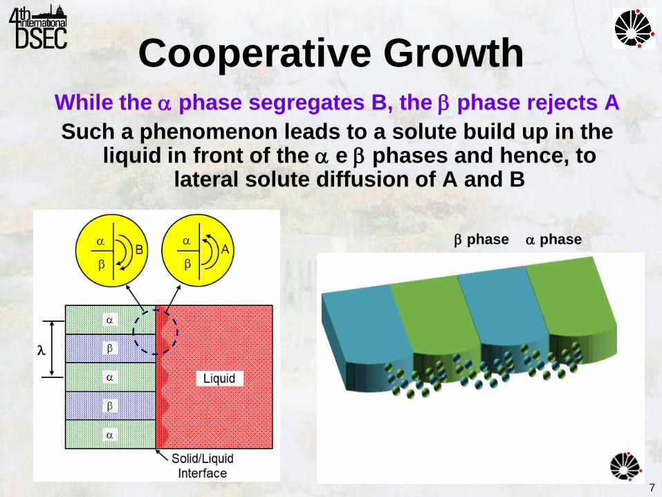
While the phase segregates B, the phase rejects A
Such a phenomenon leads to a solute build up in the liquid in front of the e phases and hence, to
lateral solute diffusion of A and B
phase
Cooperative Growth
phase
7
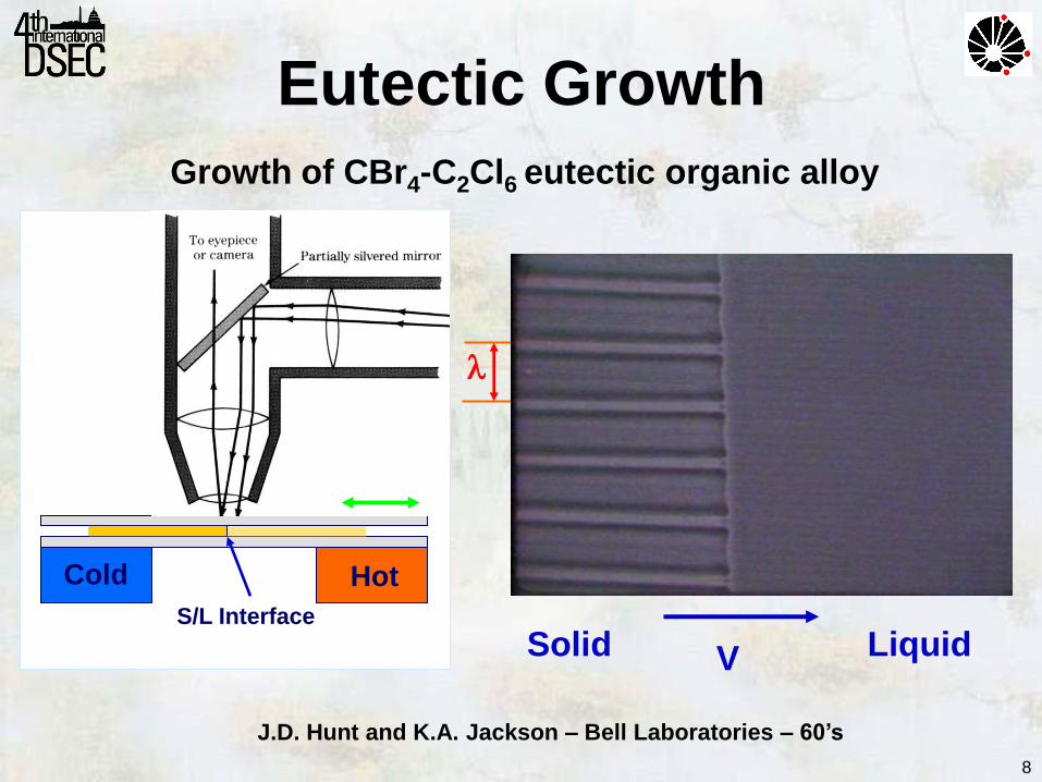
Growth of CBr4-C2Cl6 eutectic organic alloy
V Liquid Solid
Hot Cold
S/L Interface
J.D. Hunt and K.A. Jackson – Bell Laboratories – 60’s
Eutectic Growth
8
9
Previous Studies
Ni-Ni3Si - Lamellar
Al3Nb-Nb2Al - Lamellar
Ni-Al-Mo - Rod-like
Al3Nb-Nb2Al-AlNiNb - Ternary
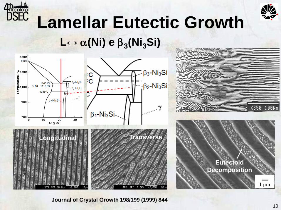
Lamellar Eutectic Growth L↔ (Ni) e 3(Ni3Si)
Longitudinal Transverse
Eutectoid
Decomposition
Journal of Crystal Growth 198/199 (1999) 844 10
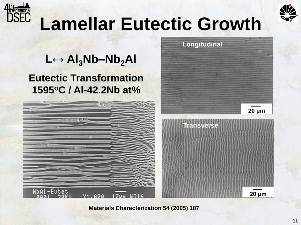
Lamellar Eutectic Growth
Materials Characterization 54 (2005) 187
Eutectic Transformation
1595oC / Al-42.2Nb at%
L↔ Al3Nb–Nb2Al
20 μm
20 μm
Longitudinal
Transverse
11
12
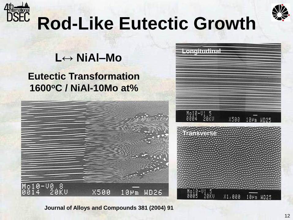
Rod-Like Eutectic Growth
Eutectic Transformation
1600oC / NiAl-10Mo at%
L↔ NiAl–Mo
Journal of Alloys and Compounds 381 (2004) 91
Longitudinal
Transverse
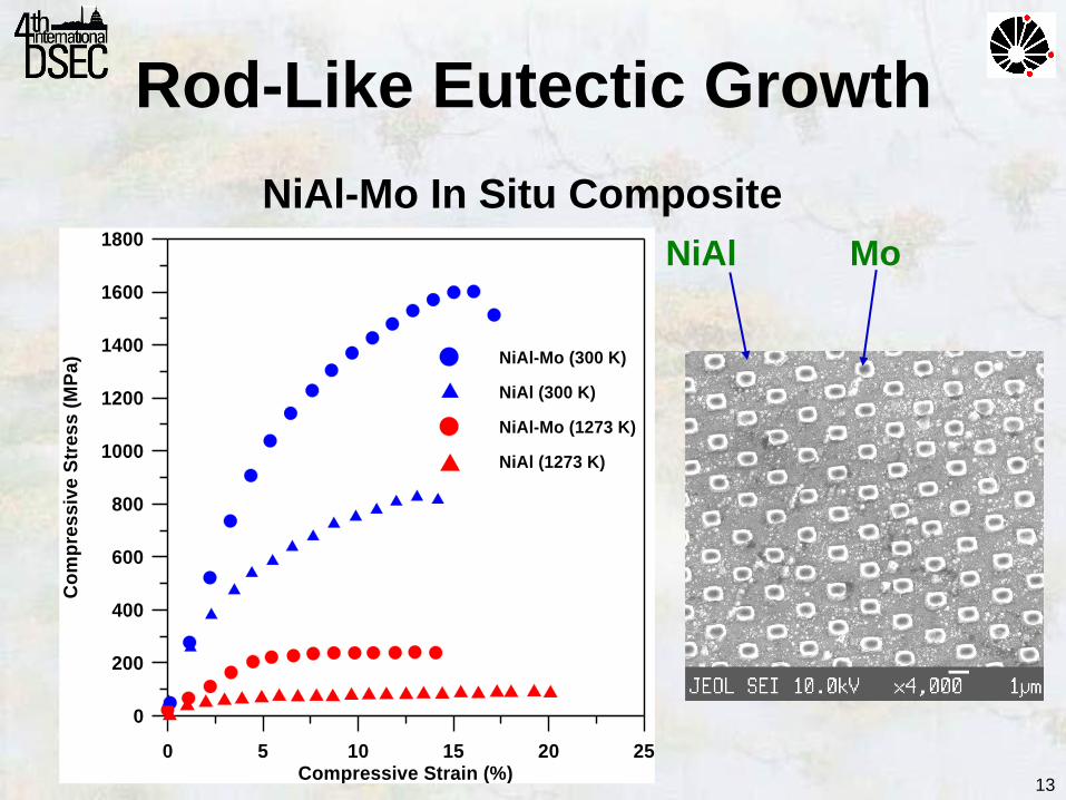
0 5 10 15 20 25Compressive Strain (%)
0
200
400
600
800
1000
1200
1400
1600
1800
Co
mp
res
siv
e S
tre
ss
(M
Pa
) NiAl-Mo (300 K)
NiAl (300 K)
NiAl-Mo (1273 K)
NiAl (1273 K)
NiAl-Mo In Situ Composite
NiAl Mo
Rod-Like Eutectic Growth
13
14
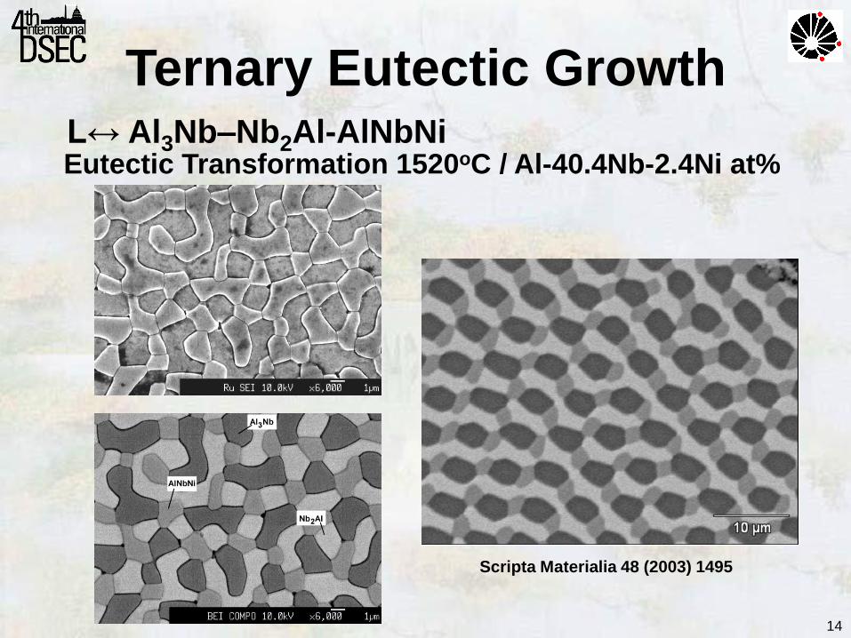
Ternary Eutectic Growth
Eutectic Transformation 1520oC / Al-40.4Nb-2.4Ni at% L↔ Al3Nb–Nb2Al-AlNbNi
Scripta Materialia 48 (2003) 1495
15
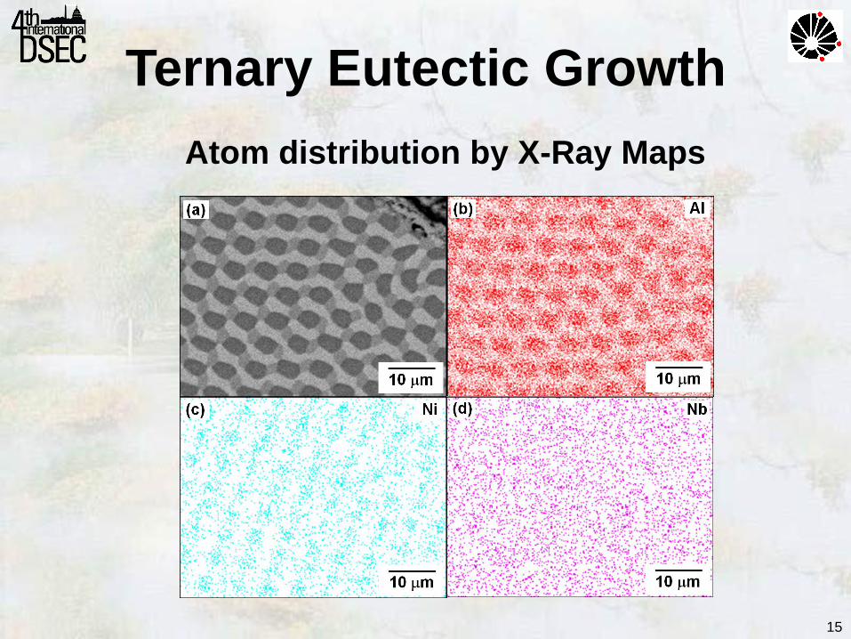
Ternary Eutectic Growth
Atom distribution by X-Ray Maps
16
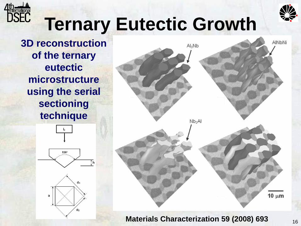
Ternary Eutectic Growth
Materials Characterization 59 (2008) 693
3D reconstruction
of the ternary
eutectic
microstructure
using the serial
sectioning
technique
17
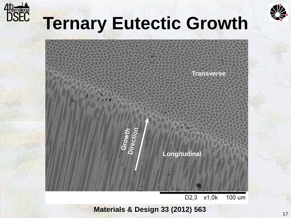
Ternary Eutectic Growth
Materials & Design 33 (2012) 563
Longitudinal
Transverse
18
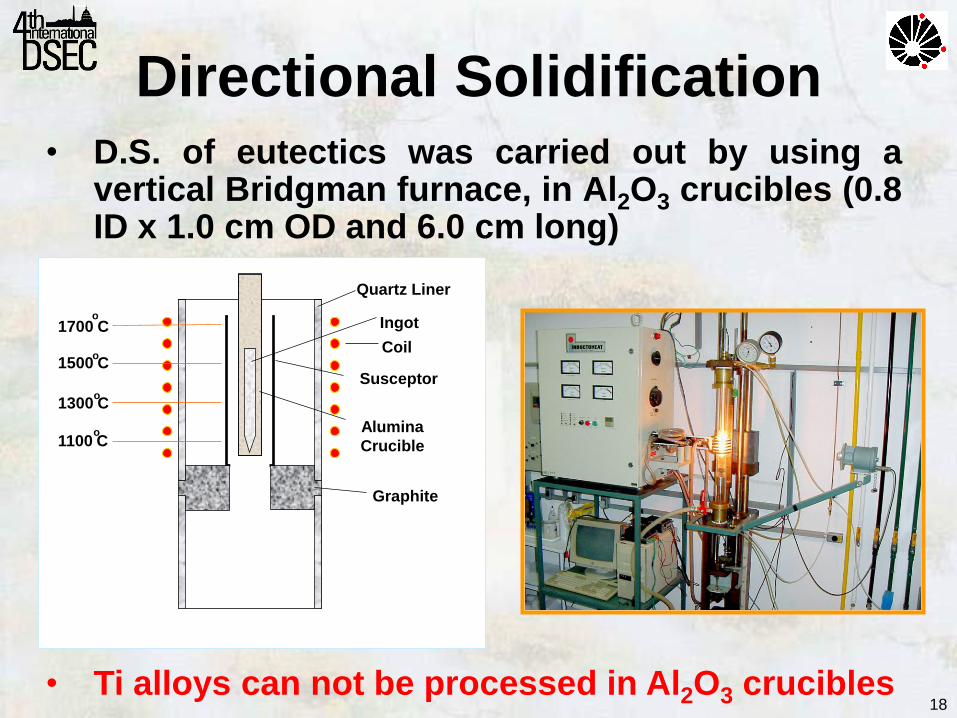
1700 C o
1500 C o
1300 C o
1100 C o
Quartz Liner
Coil
Susceptor
Graphite
Ingot
Alumina
Crucible
• D.S. of eutectics was carried out by using a vertical Bridgman furnace, in Al2O3 crucibles (0.8 ID x 1.0 cm OD and 6.0 cm long)
• Ti alloys can not be processed in Al2O3 crucibles
Directional Solidification
19
• Mechanical performance of Ti can be
considerably enhanced by combining it and
Fe, causing an eutectic transformation:
Ti: ductile BCC phase
TiFe: high strength phase • Directional solidification was carried out in a
setup that employs a water-cooled copper
crucible combined with a voltaic electric arc
moving through the sample.
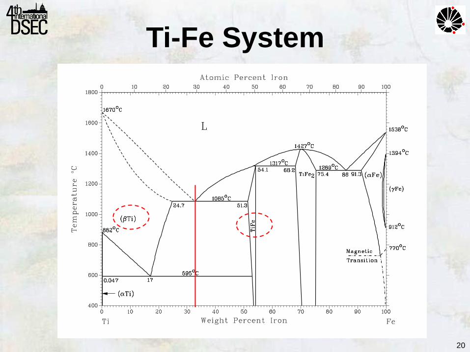
Ti-Fe System
L↔ Ti–TiFe 1095oC/Ti-32.5Fe wt%
20
A ssessed T i - F e p h ase d iag r am .Ti-Fe System
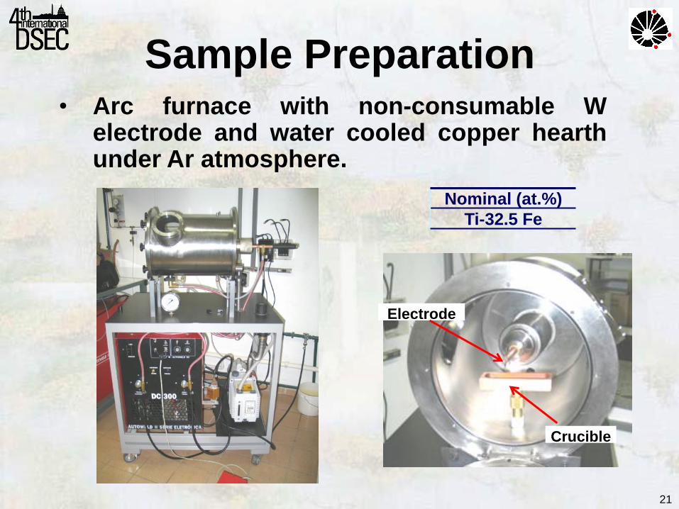
• Arc furnace with non-consumable W electrode and water cooled copper hearth under Ar atmosphere.
Crucible
Electrode
Sample Preparation
21
Nominal (at.%)
Ti-32.5 Fe
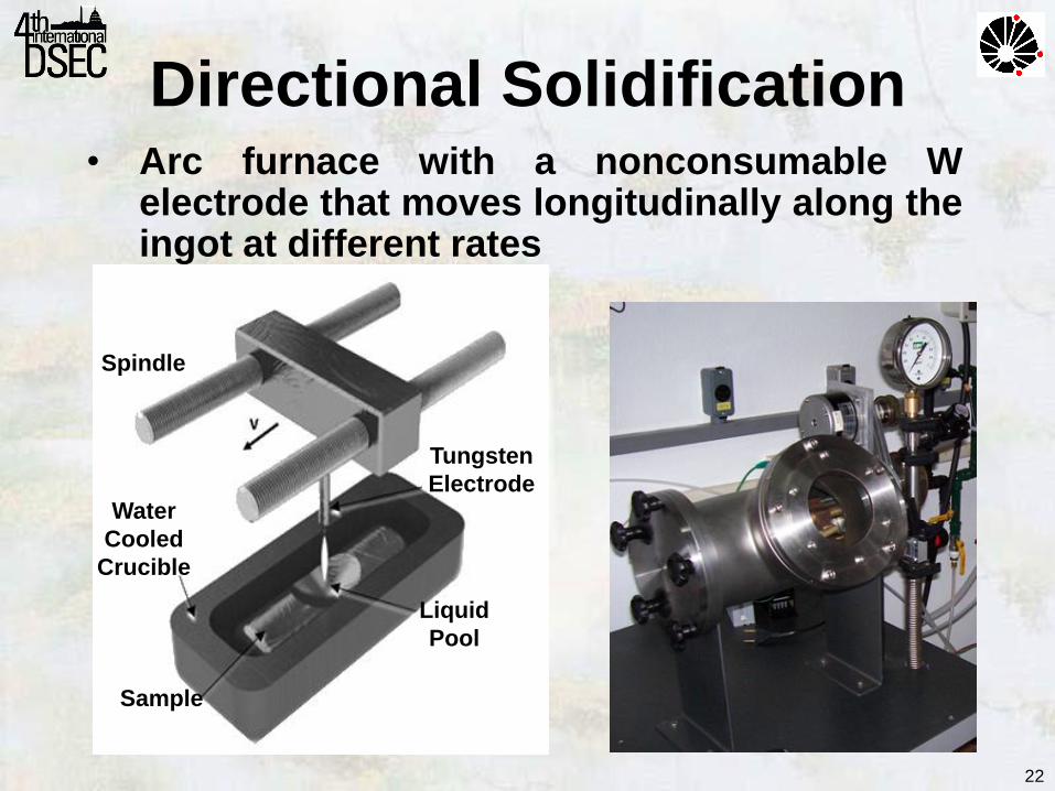
Directional Solidification
Tungsten
Electrode
Liquid
Pool
Water
Cooled
Crucible
Sample
Spindle
• Arc furnace with a nonconsumable W electrode that moves longitudinally along the ingot at different rates
22
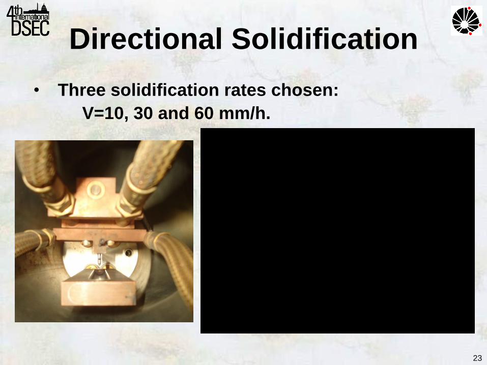
• Three solidification rates chosen:
V=10, 30 and 60 mm/h.
Directional Solidification
23
24
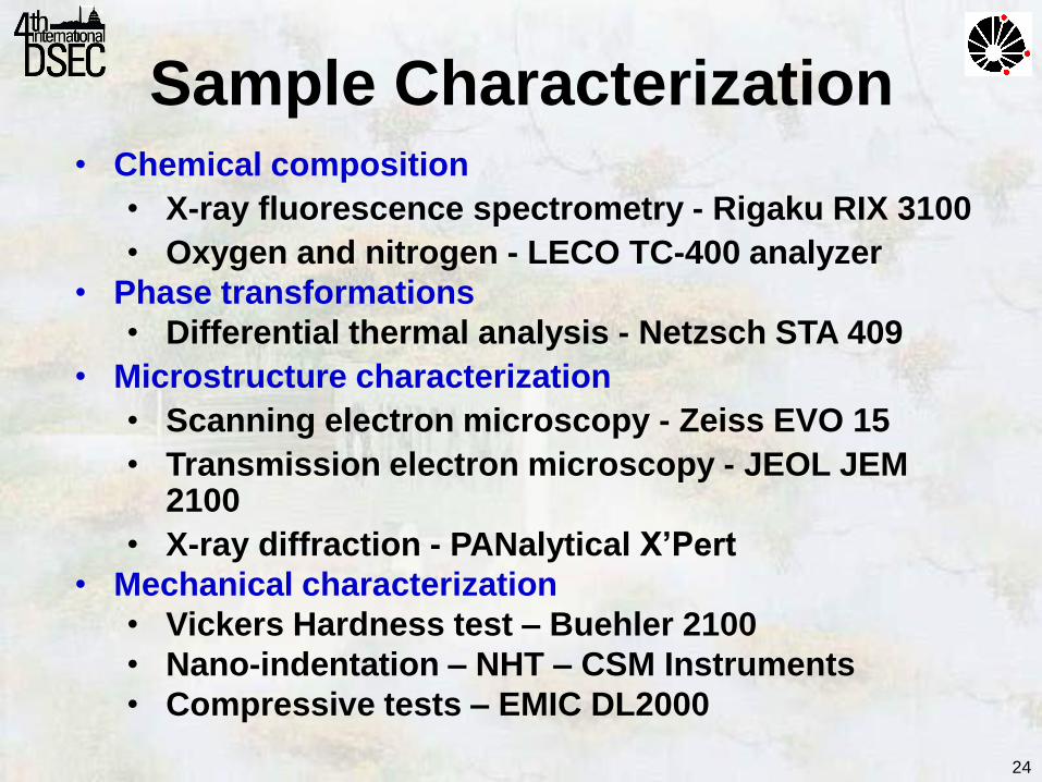
• Chemical composition
• X-ray fluorescence spectrometry - Rigaku RIX 3100
• Oxygen and nitrogen - LECO TC-400 analyzer
• Phase transformations
• Differential thermal analysis - Netzsch STA 409
• Microstructure characterization
• Scanning electron microscopy - Zeiss EVO 15
• Transmission electron microscopy - JEOL JEM 2100
• X-ray diffraction - PANalytical X’Pert
• Mechanical characterization
• Vickers Hardness test – Buehler 2100
• Nano-indentation – NHT – CSM Instruments
• Compressive tests – EMIC DL2000
Sample Characterization
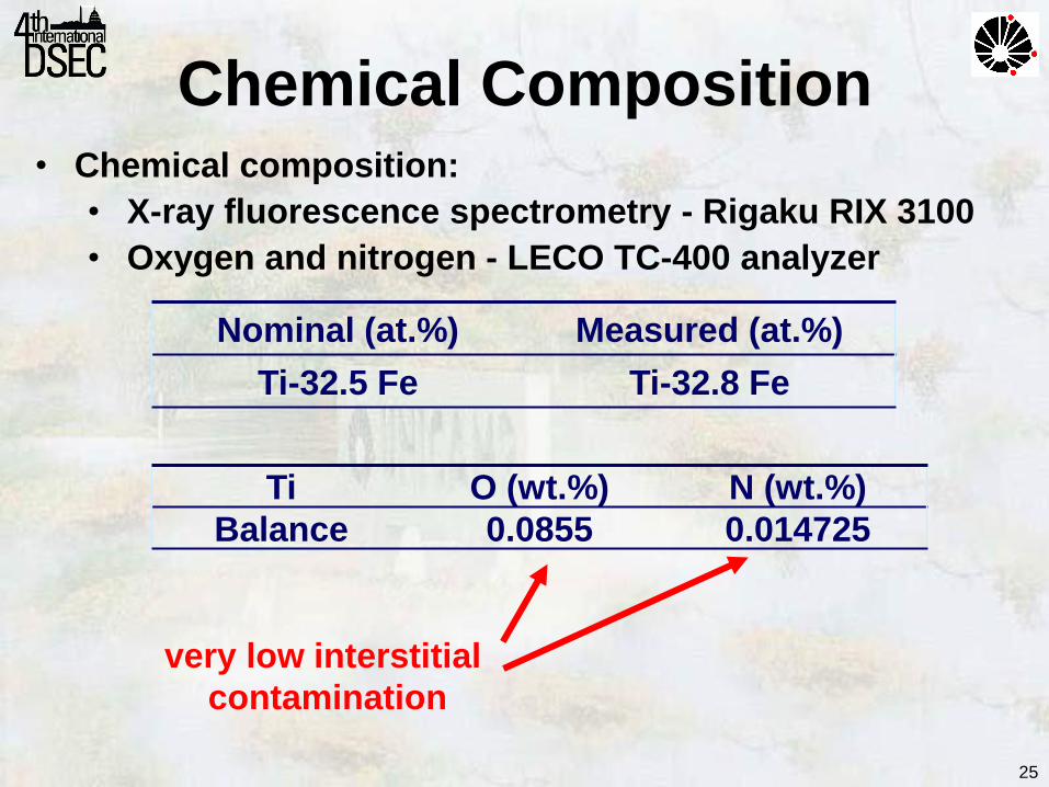
25
• Chemical composition:
• X-ray fluorescence spectrometry - Rigaku RIX 3100
• Oxygen and nitrogen - LECO TC-400 analyzer
very low interstitial
contamination
Chemical Composition
Nominal (at.%) Measured (at.%)
Ti-32.5 Fe Ti-32.8 Fe
Ti O (wt.%) N (wt.%)
Balance 0.0855 0.014725
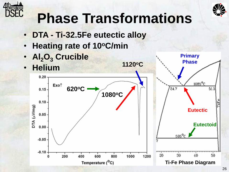
• DTA - Ti-32.5Fe eutectic alloy
• Heating rate of 10oC/min
• Al2O3 Crucible
• Helium
620oC
1080oC
1120oC
Ti-Fe Phase Diagram
Eutectic
Eutectoid
Primary
Phase
26
Phase Transformations
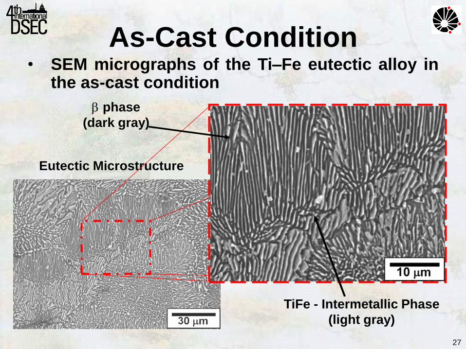
• SEM micrographs of the Ti–Fe eutectic alloy in the as-cast condition
Eutectic Microstructure
phase
(dark gray)
TiFe - Intermetallic Phase
(light gray)
27
As-Cast Condition
28
30 40 50 60 70 80 90
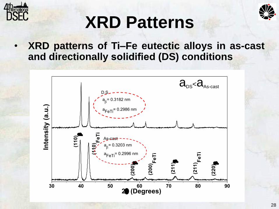
aFeTi
= 0.2996 nm
a= 0.3203 nm
(22
0)
(21
1) F
eT
i
(21
1)
(20
0) F
eT
i
(20
0)
(11
0) F
eT
i
Inte
ns
ity
(a
.u.)
2 (Degrees)
(11
0)
As-cast
aFeTi
= 0.2986 nm
D.S.
a= 0.3182 nm
XRD Patterns
• XRD patterns of Ti–Fe eutectic alloys in as-cast and directionally solidified (DS) conditions
aDS<aAs-cast
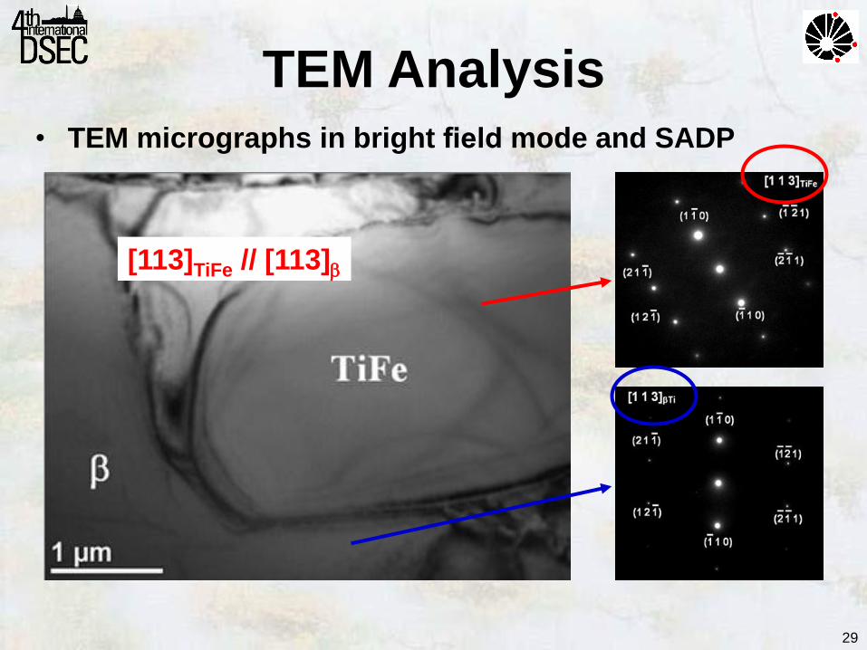
• TEM micrographs in bright field mode and SADP
[113]TiFe // [113]
29
TEM Analysis

• SEM micrographs showing transverse and longitudinal cross-sections at different rates
transvers
e
lon
gitu
din
al
10 mm/h 30 mm/h 60 mm/h
D = 50 m
D = 30 m
D= 20 m
= 1.5 m = 1.0 m = 0.7 m
Rate
30
Solidification Rate
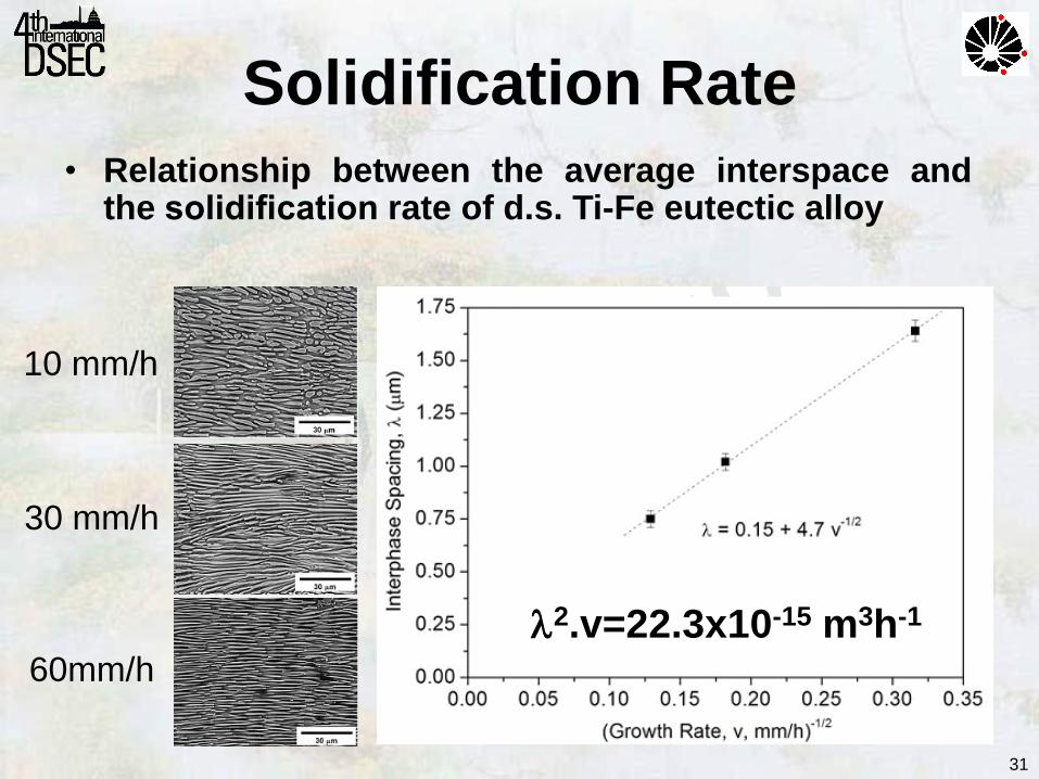
• Relationship between the average interspace and the solidification rate of d.s. Ti-Fe eutectic alloy
10 mm/h
30 mm/h
60mm/h
2.v=22.3x10⁻¹⁵ m3h-1
31
Solidification Rate
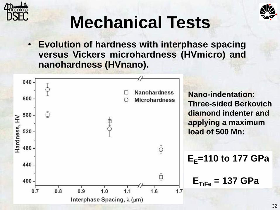
• Evolution of hardness with interphase spacing versus Vickers microhardness (HVmicro) and nanohardness (HVnano).
EE=110 to 177 GPa
ETiFe = 137 GPa
32
Mechanical Tests
Nano-indentation:
Three-sided Berkovich
diamond indenter and
applying a maximum
load of 500 Mn:
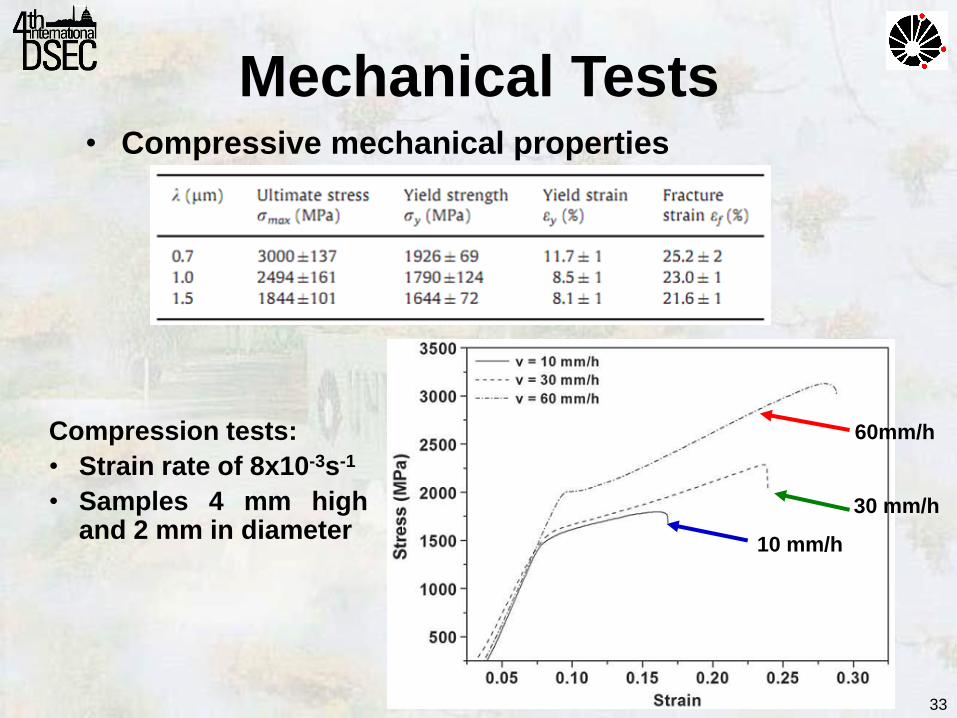
• Compressive mechanical properties
33
Compression tests:
• Strain rate of 8x10⁻³s-1
• Samples 4 mm high and 2 mm in diameter
Mechanical Tests
10 mm/h
30 mm/h
60mm/h
34
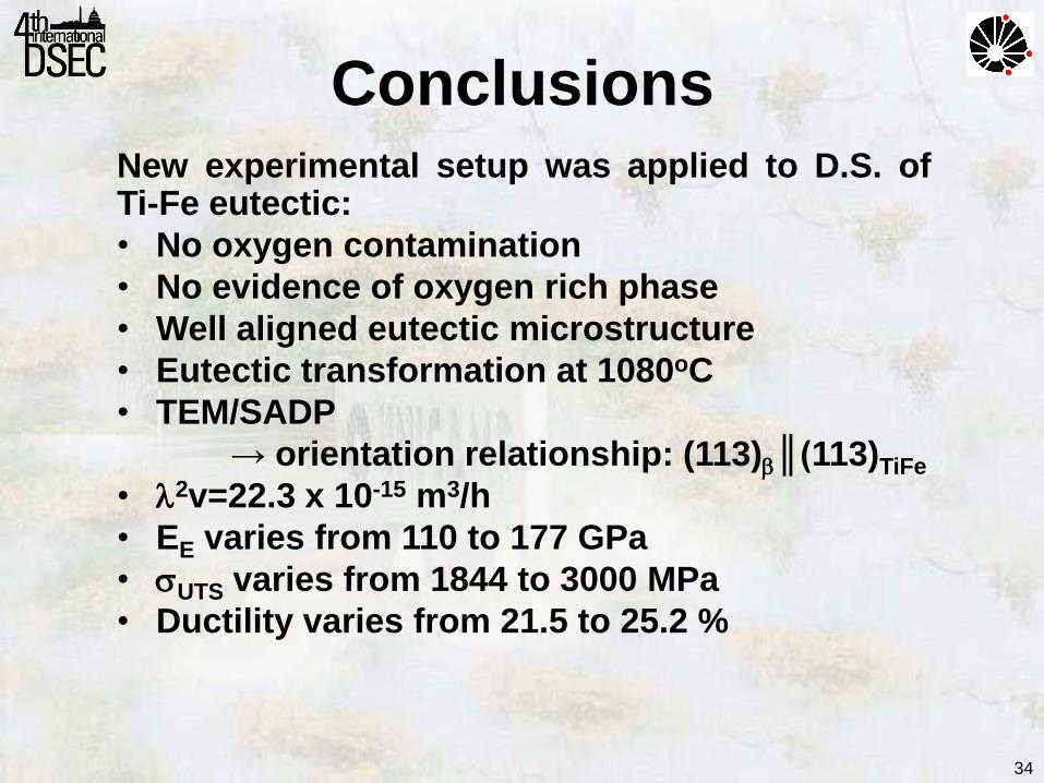
Conclusions New experimental setup was applied to D.S. of Ti-Fe eutectic:
• No oxygen contamination
• No evidence of oxygen rich phase
• Well aligned eutectic microstructure
• Eutectic transformation at 1080oC
• TEM/SADP
→ orientation relationship: (113)║(113)TiFe
• 2v=22.3 x 10⁻¹⁵ m3/h
• EE varies from 110 to 177 GPa
• UTS varies from 1844 to 3000 MPa
• Ductility varies from 21.5 to 25.2 %

35
Acknowledgments
• The State of São Paulo Research Foundation
• The Brazilian National Council for Scientific and Technological Development
for financial support

36
2014 World Cup Olympic Games Rio 2016
Visit Brazil