Embed Size (px)
DESCRIPTION
Microstructure and Corrosion Resistance of the Duplex Steel Wide-gap One-side Fluxcored Wire Welded Joints
Citation preview
© Copyright by International OCSCO World Press. All rights reserved. 2008
VOLUME 28
ISSUE 2
June
2008
Research paper 191
of Achievements in Materialsand Manufacturing Engineeringof Achievements in Materialsand Manufacturing Engineering
Microstructure and corrosion resistance of the duplex steel wide-gap one-side fluxcored wire welded joints
J. Nowacki*, P. Zając Institute of Materials Science and Engineering, Szczecin University of Technology, Al. Piastow 19, 70–310 Szczecin, Poland* Corresponding author: E-mail address: [email protected]
Received 12.04.2008; published in revised form 01.06.2008
Manufacturing and processing
AbstrActPurpose: this paper was to determine the impact of the wide-gap welding, with increased root face gap, on structure and corrosion properties of the welded joints executed on duplex steel by one-side welding on ceramic backings.Design/methodology/approach: In the described work, experiments were conducted to welding tests for selected joints, visual examinations, non-destructive testing of welded joints, X-ray examinations, and metallographic testing of welded joints.Findings: As a result of the performed inspection, decreasing of the ferrite content with the increase of the root face gap (increase of welding heat input) was observed. The minimum measured ferrite content was not lower than 28 %, and the maximum value did not exceed 69% (the permissible range being from 25 to 70 %).Research limitations/implications: Further studies on the impact of the wide-gap welding, with increased root face gap, on structure and corrosion properties of the welded joints are required.Practical implications: The performed tests and examinations of welded joints with root face gap ranging from 6 to 10 mm were intended for extending the standard range from 2 to 6 mm.Originality/value: The experimental program verified the testing methodology, and techniques of welding of the duplex steel with the wide-gap.Keywords: Welding; Microstructure of welded joints; Testing of welded joints
1. Introduction When analysing in recent years the world industry dealing in
building of large - size constructions, including chemical cargo carriers, the growing tendency to use duplex stainless steel grades can be observed. Building of large - size constructions (of duplex steel) is of multi-stage character. At different building stages there occurs necessity to execute welded joints in fixed positions. These positions as a rule enforce using maximum welding heat input which results first of all from limited possibility to increase the speed of welding in these positions. Publications relating to duplex steel welding indicate that the recommended welding heat input should range from 0.5 to 2.5 KJ/mm [1-7].
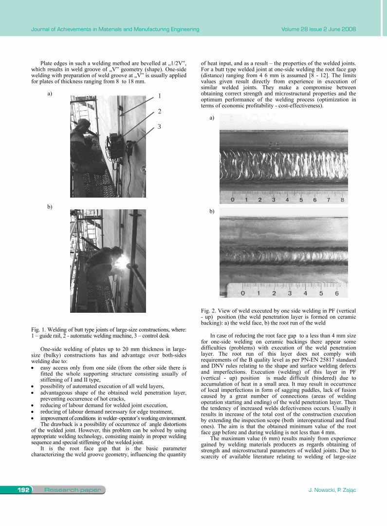
The need to extend this range is associated with welding of 3D sections at assembly in fixed positions (mainly in vertical position).When building constructions of this type for butt joints usually mechanized welding is applied using automatic welding equipment (e.g of Bug-o matic type), fluxcored wires, with active gas shield (Fig. 1).
The automatic welding equipment moves along a guide rail which is fixed to plate by means of magnets. When joining sections, one-side welding on ceramic backings is used. The root run of the weld penetration layer is formed then by means of flat ceramic backing which is then placed inside the section.
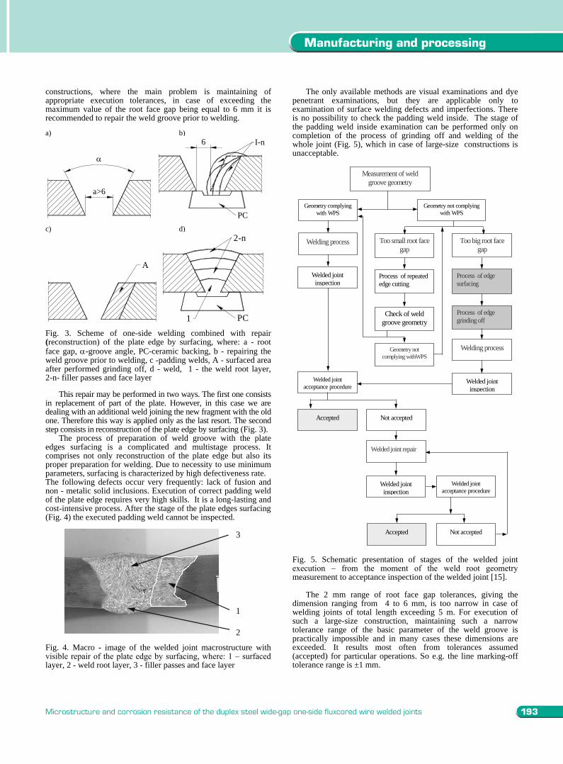
After the weld execution the backing is removable. The obtained root run of the weld does not require execution of any auxiliary operations, e.g. grinding off (Fig. 2).
1.Introduction
Research paper192
Journal of Achievements in Materials and Manufacturing Engineering
J. Nowacki, P. Zając
Volume 28 Issue 2 June 2008
Plate edges in such a welding method are bevelled at „1/2V”, which results in weld groove of „V” geometry (shape). One-side welding with preparation of weld groove at „V” is usually applied for plates of thickness ranging from 8 to 18 mm.
a) 1
2
3
b)
Fig. 1. Welding of butt type joints of large-size constructions, where: 1 – guide rail, 2 - automatic welding machine, 3 – control desk
One-side welding of plates up to 20 mm thickness in large-size (bulky) constructions has and advantage over both-sides welding due to:
easy access only from one side (from the other side there is fitted the whole supporting structure consisting usually of stiffening of I and II type, possibility of automated execution of all weld layers, advantageous shape of the obtained weld penetration layer, preventing occurrence of hot cracks, reducing of labour demand for welded joint execution, reducing of labour demand necessary for edge treatment, improvement of conditions in welder–operator’s working environment. The drawback is a possibility of occurrence of angle distortions
of the welded joint. However, this problem can be solved by using appropriate welding technology, consisting mainly in proper welding sequence and special stiffening of the welded joint.
It is the root face gap that is the basic parameter characterizing the weld groove geometry, influencing the quantity
of heat input, and as a result – the properties of the welded joints. For a butt type welded joint at one-side welding the root face gap (distance) ranging from 4 6 mm is assumed [8 - 12]. The limits values given result directly from experience in execution of similar welded joints. They make a compromise between obtaining correct strength and microstructural properties and the optimum performance of the welding process (optimization in terms of economic profitability - cost-effectiveness).
a)
b)
Fig. 2. View of weld executed by one side welding in PF (vertical - up) position (the weld penetration layer is formed on ceramic backing): a) the weld face, b) the root run of the weld
In case of reducing the root face gap to a less than 4 mm size for one-side welding on ceramic backings there appear some difficulties (problems) with execution of the weld penetration layer. The root run of this layer does not comply with requirements of the B quality level as per PN-EN 25817 standard and DNV rules relating to the shape and surface welding defects and imperfections. Execution (welding) of this layer in PF (vertical - up) position is made difficult (hindered) due to accumulation of heat in a small area. It may result in occurrence of local imperfections in form of sagging puddles, lack of fusion caused by a great number of connections (areas of welding operation starting and ending) of the weld penetration layer. Then the tendency of increased welds defectiveness occurs. Usually it results in increase of the total cost of the construction execution by extending the inspection scope (both interoperational and final ones). The aim is that the obtained minimum value of the root face gap before and during welding is not less than 4 mm.
The maximum value (6 mm) results mainly from experience gained by welding materials producers as regards obtaining of strength and microstructural parameters of welded joints. Due to scarcity of available literature relating to welding of large-size
constructions, where the main problem is maintaining of appropriate execution tolerances, in case of exceeding the maximum value of the root face gap being equal to 6 mm it is recommended to repair the weld groove prior to welding.
a) b)
a>6
6 I-n
PCc) d)
A
1
2-n
PC
Fig. 3. Scheme of one-side welding combined with repair(reconstruction) of the plate edge by surfacing, where: a - root face gap, -groove angle, PC-ceramic backing, b - repairing the weld groove prior to welding, c -padding welds, A - surfaced area after performed grinding off, d - weld, 1 - the weld root layer, 2-n- filler passes and face layer
This repair may be performed in two ways. The first one consists in replacement of part of the plate. However, in this case we are dealing with an additional weld joining the new fragment with the old one. Therefore this way is applied only as the last resort. The second step consists in reconstruction of the plate edge by surfacing (Fig. 3).
The process of preparation of weld groove with the plate edges surfacing is a complicated and multistage process. It comprises not only reconstruction of the plate edge but also its proper preparation for welding. Due to necessity to use minimum parameters, surfacing is characterized by high defectiveness rate. The following defects occur very frequently: lack of fusion and non - metalic solid inclusions. Execution of correct padding weld of the plate edge requires very high skills. It is a long-lasting and cost-intensive process. After the stage of the plate edges surfacing (Fig. 4) the executed padding weld cannot be inspected.
2
3
1
Fig. 4. Macro - image of the welded joint macrostructure with visible repair of the plate edge by surfacing, where: 1 – surfaced layer, 2 - weld root layer, 3 - filler passes and face layer
The only available methods are visual examinations and dye penetrant examinations, but they are applicable only to examination of surface welding defects and imperfections. There is no possibility to check the padding weld inside. The stage of the padding weld inside examination can be performed only on completion of the process of grinding off and welding of the whole joint (Fig. 5), which in case of large-size constructions is unacceptable.
Measurement of weld groove geometry
Welding process Too small root face gap
Geometry complying with WPS
Geometry not complying with WPS
Too big root face gap
Process of repeated edge cutting
Process of edge surfacing
Welded joint inspection
Check of weld groove geometry
Process of edge grinding off
Welding process Geometry not complying withWPS
Welded joint inspection
Welded joint acceptance procedure
Accepted Not accepted
Welded joint repair
Welded joint inspection
Welded joint acceptance procedure
Not accepted Accepted
Fig. 5. Schematic presentation of stages of the welded joint execution – from the moment of the weld root geometry measurement to acceptance inspection of the welded joint [15].
The 2 mm range of root face gap tolerances, giving the dimension ranging from 4 to 6 mm, is too narrow in case of welding joints of total length exceeding 5 m. For execution of such a large-size construction, maintaining such a narrow tolerance range of the basic parameter of the weld groove is practically impossible and in many cases these dimensions are exceeded. It results most often from tolerances assumed (accepted) for particular operations. So e.g. the line marking-off tolerance range is ±1 mm.
193
Manufacturing and processing
Microstructure and corrosion resistance of the duplex steel wide-gap one-side fluxcored wire welded joints
Plate edges in such a welding method are bevelled at „1/2V”, which results in weld groove of „V” geometry (shape). One-side welding with preparation of weld groove at „V” is usually applied for plates of thickness ranging from 8 to 18 mm.
a) 1
2
3
b)
Fig. 1. Welding of butt type joints of large-size constructions, where: 1 – guide rail, 2 - automatic welding machine, 3 – control desk
One-side welding of plates up to 20 mm thickness in large-size (bulky) constructions has and advantage over both-sides welding due to:
easy access only from one side (from the other side there is fitted the whole supporting structure consisting usually of stiffening of I and II type, possibility of automated execution of all weld layers, advantageous shape of the obtained weld penetration layer, preventing occurrence of hot cracks, reducing of labour demand for welded joint execution, reducing of labour demand necessary for edge treatment, improvement of conditions in welder–operator’s working environment. The drawback is a possibility of occurrence of angle distortions
of the welded joint. However, this problem can be solved by using appropriate welding technology, consisting mainly in proper welding sequence and special stiffening of the welded joint.
It is the root face gap that is the basic parameter characterizing the weld groove geometry, influencing the quantity
of heat input, and as a result – the properties of the welded joints. For a butt type welded joint at one-side welding the root face gap (distance) ranging from 4 6 mm is assumed [8 - 12]. The limits values given result directly from experience in execution of similar welded joints. They make a compromise between obtaining correct strength and microstructural properties and the optimum performance of the welding process (optimization in terms of economic profitability - cost-effectiveness).
a)
b)
Fig. 2. View of weld executed by one side welding in PF (vertical - up) position (the weld penetration layer is formed on ceramic backing): a) the weld face, b) the root run of the weld
In case of reducing the root face gap to a less than 4 mm size for one-side welding on ceramic backings there appear some difficulties (problems) with execution of the weld penetration layer. The root run of this layer does not comply with requirements of the B quality level as per PN-EN 25817 standard and DNV rules relating to the shape and surface welding defects and imperfections. Execution (welding) of this layer in PF (vertical - up) position is made difficult (hindered) due to accumulation of heat in a small area. It may result in occurrence of local imperfections in form of sagging puddles, lack of fusion caused by a great number of connections (areas of welding operation starting and ending) of the weld penetration layer. Then the tendency of increased welds defectiveness occurs. Usually it results in increase of the total cost of the construction execution by extending the inspection scope (both interoperational and final ones). The aim is that the obtained minimum value of the root face gap before and during welding is not less than 4 mm.
The maximum value (6 mm) results mainly from experience gained by welding materials producers as regards obtaining of strength and microstructural parameters of welded joints. Due to scarcity of available literature relating to welding of large-size
constructions, where the main problem is maintaining of appropriate execution tolerances, in case of exceeding the maximum value of the root face gap being equal to 6 mm it is recommended to repair the weld groove prior to welding.
a) b)
a>6
6 I-n
PCc) d)
A
1
2-n
PC
Fig. 3. Scheme of one-side welding combined with repair(reconstruction) of the plate edge by surfacing, where: a - root face gap, -groove angle, PC-ceramic backing, b - repairing the weld groove prior to welding, c -padding welds, A - surfaced area after performed grinding off, d - weld, 1 - the weld root layer, 2-n- filler passes and face layer
This repair may be performed in two ways. The first one consists in replacement of part of the plate. However, in this case we are dealing with an additional weld joining the new fragment with the old one. Therefore this way is applied only as the last resort. The second step consists in reconstruction of the plate edge by surfacing (Fig. 3).
The process of preparation of weld groove with the plate edges surfacing is a complicated and multistage process. It comprises not only reconstruction of the plate edge but also its proper preparation for welding. Due to necessity to use minimum parameters, surfacing is characterized by high defectiveness rate. The following defects occur very frequently: lack of fusion and non - metalic solid inclusions. Execution of correct padding weld of the plate edge requires very high skills. It is a long-lasting and cost-intensive process. After the stage of the plate edges surfacing (Fig. 4) the executed padding weld cannot be inspected.
2
3
1
Fig. 4. Macro - image of the welded joint macrostructure with visible repair of the plate edge by surfacing, where: 1 – surfaced layer, 2 - weld root layer, 3 - filler passes and face layer
The only available methods are visual examinations and dye penetrant examinations, but they are applicable only to examination of surface welding defects and imperfections. There is no possibility to check the padding weld inside. The stage of the padding weld inside examination can be performed only on completion of the process of grinding off and welding of the whole joint (Fig. 5), which in case of large-size constructions is unacceptable.
Measurement of weld groove geometry
Welding process Too small root face gap
Geometry complying with WPS
Geometry not complying with WPS
Too big root face gap
Process of repeated edge cutting
Process of edge surfacing
Welded joint inspection
Check of weld groove geometry
Process of edge grinding off
Welding process Geometry not complying withWPS
Welded joint inspection
Welded joint acceptance procedure
Accepted Not accepted
Welded joint repair
Welded joint inspection
Welded joint acceptance procedure
Not accepted Accepted
Fig. 5. Schematic presentation of stages of the welded joint execution – from the moment of the weld root geometry measurement to acceptance inspection of the welded joint [15].
The 2 mm range of root face gap tolerances, giving the dimension ranging from 4 to 6 mm, is too narrow in case of welding joints of total length exceeding 5 m. For execution of such a large-size construction, maintaining such a narrow tolerance range of the basic parameter of the weld groove is practically impossible and in many cases these dimensions are exceeded. It results most often from tolerances assumed (accepted) for particular operations. So e.g. the line marking-off tolerance range is ±1 mm.
Research paper194
Journal of Achievements in Materials and Manufacturing Engineering
J. Nowacki, P. Zając
Volume 28 Issue 2 June 2008
The plasma arc cutting tolerance range is ±2 mm. Measuring errors resulting from measuring instruments are contained in ±1 mm tolerance (allowance). In some cases values of tolerances for particular operations are summed up (tolerance stack-up) and the obtained dimension of the root face gap is exceeded. Most often the plus tolerances are extended, i.e the dimension of the root face gap is higher than 6 mm (within 6 -10 mm limits).
Thus the surfacing process is consciously introduced into the process of basic execution of the welded joint. Generally in welding procedures in case of gaps >6 mm the surfacing of plate edges prior to welding is applied [13 - 15]. In order to execute one-side welded joints without using the edge surfacing process it is necessary to extend the range of root face gap tolerances.
The research and tests conducted at the Technical University of Szczecin in cooperation with the Szczecin New Shipyard permitted to determine the impact of the wide-gap welding, with increased root face gap, on structure and corrosion properties of the welded joints executed on duplex steel by one-side welding on ceramic backings.
2. Welding tests of selected joints Welding tests were performed based on the elaborated experiment
plan. 9 welded joints of 1.000 mm length each were executed. Three-plate thickness was assumed. For each of them welding with root face gap of the weld groove, equal to 6, 8 and 10 mm, was performed. Table 1 presents characteristics of welded joints [15].
Particular joints were executed using FCAW – Flux Cored Arc Welding – 136 - one-side welding with the weld penetration layer on ceramic backing on plates (g [thickness] = 16.5mm) made of duplex steel UNS S31803 using filler metal DW329AP/ C1 (100%CO2). The following examinations were performed:
3. Non-destructive testing of welded joints
They were intended for the evaluation of quality of welded joints. The requirements specified for the B quality level as per PN-EN 25817 standard were assumed as a criterion.
Table 1. Characteristics of executed welded joints. No. of
theweld
Plate thickness
mm
Rootface gap
mm
Grooveangledeg
Welding position
Welding heat input range
1 9 6 45 PF 2.02 2.352 9 8 45 PF 2.34 2.803 9 10 45 PF 1.58 2.584 14.5 6 45 PF 1.80 2.945 14.5 8 45 PF 1.94 3.516 14.5 10 45 PF 1.94 3.947 18.5 6 45 PF 1.63 3.558 18.5 8 45 PF 2.13 3.829 18.5 10 45 PF 2.37 3.93
4.Visual examinations They were performed based on the PN-EN 970 standard. All
the welded joints covered by the analysis complied with the
requirements for the B quality level. Table 2 presents appearance of the weld faces and the root runs of particular welded joints with characteristic dimensions given. On the basis of the performed visual examinations the following was found out:
increase of the root run reinforcement width (maximum by2.5 mm) with increase of the root face gap, increase of the root run reinforcement width (maximum by4.5 mm) with increase of the root face gap, occurrence of undercutting of the root run of the weld on welded test plates on both sides, with root face gap exceeding 8 mm. Permanent character of these undercuts shows that it is necessary to modify the construction of ceramic backing (due to insufficient working area). These undercuts are easily removable because of small depth (less than 0.3 mm). All the test plates complied with the requirements for the B quality level as per PN-EN 25817 standard.
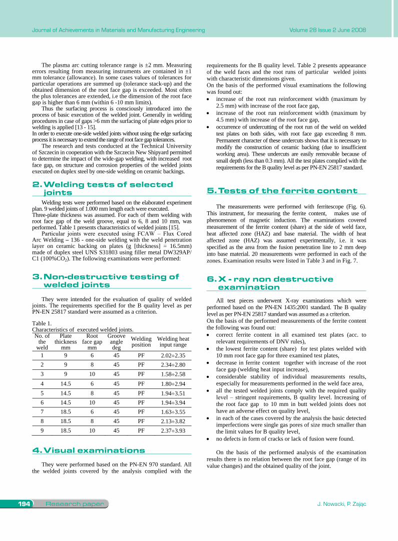
5. Tests of the ferrite content The measurements were performed with ferritescope (Fig. 6).
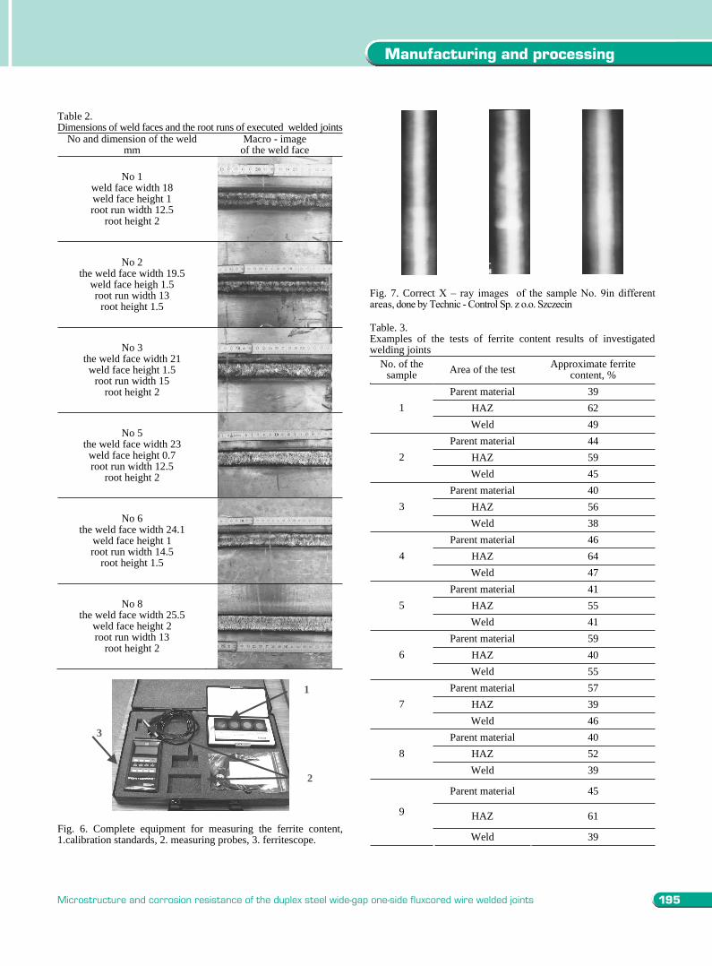
This instrument, for measuring the ferrite content, makes use of phenomenon of magnetic induction. The examinations covered measurement of the ferrite content (share) at the side of weld face, heat affected zone (HAZ) and base material. The width of heat affected zone (HAZ) was assumed experimentally, i.e. it was specified as the area from the fusion penetration line to 2 mm deep into base material. 20 measurements were performed in each of the zones. Examination results were listed in Table 3 and in Fig. 7.
6. X - ray non destructive examination All test pieces underwent X-ray examinations which were
performed based on the PN-EN 1435:2001 standard. The B quality level as per PN-EN 25817 standard was assumed as a criterion. On the basis of the performed measurements of the ferrite content the following was found out:
correct ferrite content in all examined test plates (acc. to relevant requirements of DNV rules), the lowest ferrite content (share) for test plates welded with10 mm root face gap for three examined test plates, decrease in ferrite content together with increase of the root face gap (welding heat input increase), considerable stability of individual measurements results, especially for measurements performed in the weld face area, all the tested welded joints comply with the required quality level – stringent requirements, B quality level. Increasing of the root face gap to 10 mm in butt welded joints does not have an adverse effect on quality level, in each of the cases covered by the analysis the basic detected imperfections were single gas pores of size much smaller than the limit values for B quality level, no defects in form of cracks or lack of fusion were found.
On the basis of the performed analysis of the examination results there is no relation between the root face gap (range of its value changes) and the obtained quality of the joint.
Table 2. Dimensions of weld faces and the root runs of executed welded joints
No and dimension of the weld mm
Macro - image of the weld face
No 1 weld face width 18 weld face height 1 root run width 12.5
root height 2
No 2 the weld face width 19.5
weld face heigh 1.5 root run width 13
root height 1.5
No 3 the weld face width 21 weld face height 1.5
root run width 15 root height 2
No 5 the weld face width 23 weld face height 0.7 root run width 12.5
root height 2
No 6 the weld face width 24.1
weld face height 1 root run width 14.5
root height 1.5
No 8 the weld face width 25.5
weld face height 2 root run width 13
root height 2
1
2
3
Fig. 6. Complete equipment for measuring the ferrite content, 1.calibration standards, 2. measuring probes, 3. ferritescope.
Fig. 7. Correct X – ray images of the sample No. 9in different areas, done by Technic - Control Sp. z o.o. Szczecin
Table. 3. Examples of the tests of ferrite content results of investigated welding joints
No. of the sample Area of the test Approximate ferrite
content, % Parent material 39
HAZ 62 1Weld 49
Parent material 44 HAZ 59 2Weld 45
Parent material 40 HAZ 56 3Weld 38
Parent material 46 HAZ 64 4Weld 47
Parent material 41 HAZ 55 5Weld 41
Parent material 59 HAZ 40 6Weld 55
Parent material 57 HAZ 39 7Weld 46
Parent material 40 HAZ 52 8Weld 39
Parent material 45
HAZ 61 9
Weld 39
2.Weldingtestsofselectedjoints
3.Non-destructivetestingofweldedjoints
5.testsoftheferritecontent
4.Visualexaminations
6.X-raynondestructiveexamination
195
Manufacturing and processing
Microstructure and corrosion resistance of the duplex steel wide-gap one-side fluxcored wire welded joints
The plasma arc cutting tolerance range is ±2 mm. Measuring errors resulting from measuring instruments are contained in ±1 mm tolerance (allowance). In some cases values of tolerances for particular operations are summed up (tolerance stack-up) and the obtained dimension of the root face gap is exceeded. Most often the plus tolerances are extended, i.e the dimension of the root face gap is higher than 6 mm (within 6 -10 mm limits).
Thus the surfacing process is consciously introduced into the process of basic execution of the welded joint. Generally in welding procedures in case of gaps >6 mm the surfacing of plate edges prior to welding is applied [13 - 15]. In order to execute one-side welded joints without using the edge surfacing process it is necessary to extend the range of root face gap tolerances.
The research and tests conducted at the Technical University of Szczecin in cooperation with the Szczecin New Shipyard permitted to determine the impact of the wide-gap welding, with increased root face gap, on structure and corrosion properties of the welded joints executed on duplex steel by one-side welding on ceramic backings.
2. Welding tests of selected joints Welding tests were performed based on the elaborated experiment
plan. 9 welded joints of 1.000 mm length each were executed. Three-plate thickness was assumed. For each of them welding with root face gap of the weld groove, equal to 6, 8 and 10 mm, was performed. Table 1 presents characteristics of welded joints [15].
Particular joints were executed using FCAW – Flux Cored Arc Welding – 136 - one-side welding with the weld penetration layer on ceramic backing on plates (g [thickness] = 16.5mm) made of duplex steel UNS S31803 using filler metal DW329AP/ C1 (100%CO2). The following examinations were performed:
3. Non-destructive testing of welded joints
They were intended for the evaluation of quality of welded joints. The requirements specified for the B quality level as per PN-EN 25817 standard were assumed as a criterion.
Table 1. Characteristics of executed welded joints. No. of
theweld
Plate thickness
mm
Rootface gap
mm
Grooveangledeg
Welding position
Welding heat input range
1 9 6 45 PF 2.02 2.352 9 8 45 PF 2.34 2.803 9 10 45 PF 1.58 2.584 14.5 6 45 PF 1.80 2.945 14.5 8 45 PF 1.94 3.516 14.5 10 45 PF 1.94 3.947 18.5 6 45 PF 1.63 3.558 18.5 8 45 PF 2.13 3.829 18.5 10 45 PF 2.37 3.93
4.Visual examinations They were performed based on the PN-EN 970 standard. All
the welded joints covered by the analysis complied with the
requirements for the B quality level. Table 2 presents appearance of the weld faces and the root runs of particular welded joints with characteristic dimensions given. On the basis of the performed visual examinations the following was found out:
increase of the root run reinforcement width (maximum by2.5 mm) with increase of the root face gap, increase of the root run reinforcement width (maximum by4.5 mm) with increase of the root face gap, occurrence of undercutting of the root run of the weld on welded test plates on both sides, with root face gap exceeding 8 mm. Permanent character of these undercuts shows that it is necessary to modify the construction of ceramic backing (due to insufficient working area). These undercuts are easily removable because of small depth (less than 0.3 mm). All the test plates complied with the requirements for the B quality level as per PN-EN 25817 standard.
5. Tests of the ferrite content The measurements were performed with ferritescope (Fig. 6).
This instrument, for measuring the ferrite content, makes use of phenomenon of magnetic induction. The examinations covered measurement of the ferrite content (share) at the side of weld face, heat affected zone (HAZ) and base material. The width of heat affected zone (HAZ) was assumed experimentally, i.e. it was specified as the area from the fusion penetration line to 2 mm deep into base material. 20 measurements were performed in each of the zones. Examination results were listed in Table 3 and in Fig. 7.
6. X - ray non destructive examination All test pieces underwent X-ray examinations which were
performed based on the PN-EN 1435:2001 standard. The B quality level as per PN-EN 25817 standard was assumed as a criterion. On the basis of the performed measurements of the ferrite content the following was found out:
correct ferrite content in all examined test plates (acc. to relevant requirements of DNV rules), the lowest ferrite content (share) for test plates welded with10 mm root face gap for three examined test plates, decrease in ferrite content together with increase of the root face gap (welding heat input increase), considerable stability of individual measurements results, especially for measurements performed in the weld face area, all the tested welded joints comply with the required quality level – stringent requirements, B quality level. Increasing of the root face gap to 10 mm in butt welded joints does not have an adverse effect on quality level, in each of the cases covered by the analysis the basic detected imperfections were single gas pores of size much smaller than the limit values for B quality level, no defects in form of cracks or lack of fusion were found.
On the basis of the performed analysis of the examination results there is no relation between the root face gap (range of its value changes) and the obtained quality of the joint.
Table 2. Dimensions of weld faces and the root runs of executed welded joints
No and dimension of the weld mm
Macro - image of the weld face
No 1 weld face width 18 weld face height 1 root run width 12.5
root height 2
No 2 the weld face width 19.5
weld face heigh 1.5 root run width 13
root height 1.5
No 3 the weld face width 21 weld face height 1.5
root run width 15 root height 2
No 5 the weld face width 23 weld face height 0.7 root run width 12.5
root height 2
No 6 the weld face width 24.1
weld face height 1 root run width 14.5
root height 1.5
No 8 the weld face width 25.5
weld face height 2 root run width 13
root height 2
1
2
3
Fig. 6. Complete equipment for measuring the ferrite content, 1.calibration standards, 2. measuring probes, 3. ferritescope.
Fig. 7. Correct X – ray images of the sample No. 9in different areas, done by Technic - Control Sp. z o.o. Szczecin
Table. 3. Examples of the tests of ferrite content results of investigated welding joints
No. of the sample Area of the test Approximate ferrite
content, % Parent material 39
HAZ 62 1Weld 49
Parent material 44 HAZ 59 2Weld 45
Parent material 40 HAZ 56 3Weld 38
Parent material 46 HAZ 64 4Weld 47
Parent material 41 HAZ 55 5Weld 41
Parent material 59 HAZ 40 6Weld 55
Parent material 57 HAZ 39 7Weld 46
Parent material 40 HAZ 52 8Weld 39
Parent material 45
HAZ 61 9
Weld 39
Research paper196
Journal of Achievements in Materials and Manufacturing Engineering
J. Nowacki, P. Zając
Volume 28 Issue 2 June 2008
7. Metallographic examination of welded joints
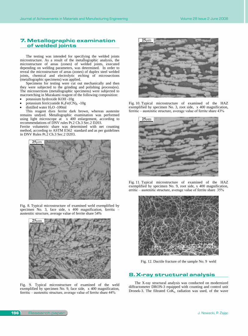
The testing was intended for specifying the welded joints microstructure. As a result of the metallographic analysis, the microstructure of areas (zones) of welded joints, executed depending on welding parameters, was determined. In order to reveal the microstructure of areas (zones) of duplex steel welded joints, chemical and electrolytic etching of microsections (metallographic specimens) was applied.
Specimens for testing were cut out mechanically and then they were subjected to the grinding and polishing process(es). The microsections (metallographic specimens) were subjected to macroetching in Murakami reagent of the following composition:
potassium hydroxide KOH -10g potassium ferricyanide K3Fe(CN)6 -10g distilled water H2O -100mlThis reagent dyes ferrite dark brown, whereas austenite
remains undyed. Metallographic examination was performed using light microscope at x 400 enlargement, according to recommendations of DNV rules Pt.2 Ch.3 Sec.2 D203. Ferrite volumetric share was determined with net counting method, according to ASTM E562 standard and as per guidelines in DNV Rules Pt.2 Ch.3 Sec.2 D203.
Fig. 8. Typical microstructure of examined weld exemplified by specimen No. 3, face side, x 400 magnification, ferritic – austenitic structure, average value of ferrite share 54%
Fig. 9. Typical microstructure of examined of the weld exemplified by specimen No. 9, face side, x 400 magnification, ferritic – austenitic structure, average value of ferrite share 44%
Fig. 10. Typical microstructure of examined of the HAZ exemplified by specimen No. 3, root side, x 400 magnification, ferritic – austenitic structure, average value of ferrite share 43%
Fig. 11. Typical microstructure of examined of the HAZ exemplified by specimen No. 9, root side, x 400 magnification, erritic – austenitic structure, average value of ferrite share 35%
Fig. 12. Ductile fracture of the sample No. 9 weld
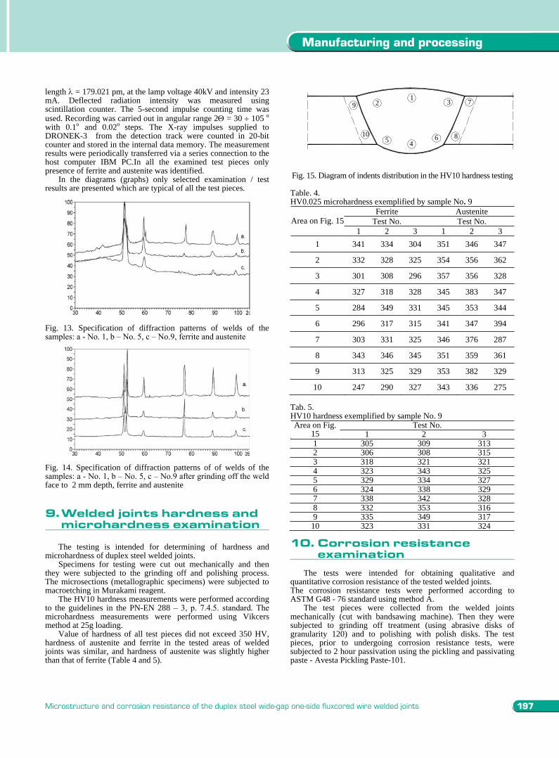
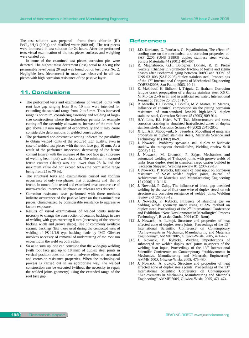
8. X-ray structural analysisThe X-ray structural analysis was conducted on modernized
diffractometer DRON-3 equipped with counting and control unit Dronek-3. The filtrated CoK radiation was used, of the wave
length = 179.021 pm, at the lamp voltage 40kV and intensity 23 mA. Deflected radiation intensity was measured using scintillation counter. The 5-second impulse counting time was used. Recording was carried out in angular range 2 = 30 105 o
with 0.1o and 0.02o steps. The X-ray impulses supplied to DRONEK-3 from the detection track were counted in 20-bit counter and stored in the internal data memory. The measurement results were periodically transferred via a series connection to the host computer IBM PC.In all the examined test pieces only presence of ferrite and austenite was identified.
In the diagrams (graphs) only selected examination / test results are presented which are typical of all the test pieces.
Fig. 13. Specification of diffraction patterns of welds of the samples: a - No. 1, b – No. 5, c – No.9, ferrite and austenite
Fig. 14. Specification of diffraction patterns of of welds of the samples: a - No. 1, b – No. 5, c – No.9 after grinding off the weld face to 2 mm depth, ferrite and austenite 9. Welded joints hardness and microhardness examination
The testing is intended for determining of hardness and
microhardness of duplex steel welded joints. Specimens for testing were cut out mechanically and then
they were subjected to the grinding off and polishing process. The microsections (metallographic specimens) were subjected to macroetching in Murakami reagent.
The HV10 hardness measurements were performed according to the guidelines in the PN-EN 288 – 3, p. 7.4.5. standard. The microhardness measurements were performed using Vikcers method at 25g loading.
Value of hardness of all test pieces did not exceed 350 HV, hardness of austenite and ferrite in the tested areas of welded joints was similar, and hardness of austenite was slightly higher than that of ferrite (Table 4 and 5).
1 3
8
9 2
5 46
7
10
Fig. 15. Diagram of indents distribution in the HV10 hardness testing Table. 4. HV0.025 microhardness exemplified by sample No. 9
Ferrite Austenite Test No. Test No. Area on Fig. 15
1 2 3 1 2 3 1 341 334 304 351 346 347
2 332 328 325 354 356 362
3 301 308 296 357 356 328
4 327 318 328 345 383 347
5 284 349 331 345 353 344
6 296 317 315 341 347 394
7 303 331 325 346 376 287
8 343 346 345 351 359 361
9 313 325 329 353 382 329
10 247 290 327 343 336 275 Tab. 5. HV10 hardness exemplified by sample No. 9
Test No. Area on Fig. 15 1 2 3 1 305 309 313 2 306 308 315 3 318 321 321 4 323 343 325 5 329 334 327 6 324 338 329 7 338 342 328 8 332 353 316 9 335 349 317
10 323 331 324
10. Corrosion resistance examination The tests were intended for obtaining qualitative and
quantitative corrosion resistance of the tested welded joints. The corrosion resistance tests were performed according to ASTM G48 - 76 standard using method A.
The test pieces were collected from the welded joints mechanically (cut with bandsawing machine). Then they were subjected to grinding off treatment (using abrasive disks of granularity 120) and to polishing with polish disks. The test pieces, prior to undergoing corrosion resistance tests, were subjected to 2 hour passivation using the pickling and passivating paste - Avesta Pickling Paste-101.
7.Metallographicexaminationofweldedjoints
8.X-raystructuralanalysis
197
Manufacturing and processing
Microstructure and corrosion resistance of the duplex steel wide-gap one-side fluxcored wire welded joints
7. Metallographic examination of welded joints
The testing was intended for specifying the welded joints microstructure. As a result of the metallographic analysis, the microstructure of areas (zones) of welded joints, executed depending on welding parameters, was determined. In order to reveal the microstructure of areas (zones) of duplex steel welded joints, chemical and electrolytic etching of microsections (metallographic specimens) was applied.
Specimens for testing were cut out mechanically and then they were subjected to the grinding and polishing process(es). The microsections (metallographic specimens) were subjected to macroetching in Murakami reagent of the following composition:
potassium hydroxide KOH -10g potassium ferricyanide K3Fe(CN)6 -10g distilled water H2O -100mlThis reagent dyes ferrite dark brown, whereas austenite
remains undyed. Metallographic examination was performed using light microscope at x 400 enlargement, according to recommendations of DNV rules Pt.2 Ch.3 Sec.2 D203. Ferrite volumetric share was determined with net counting method, according to ASTM E562 standard and as per guidelines in DNV Rules Pt.2 Ch.3 Sec.2 D203.
Fig. 8. Typical microstructure of examined weld exemplified by specimen No. 3, face side, x 400 magnification, ferritic – austenitic structure, average value of ferrite share 54%
Fig. 9. Typical microstructure of examined of the weld exemplified by specimen No. 9, face side, x 400 magnification, ferritic – austenitic structure, average value of ferrite share 44%
Fig. 10. Typical microstructure of examined of the HAZ exemplified by specimen No. 3, root side, x 400 magnification, ferritic – austenitic structure, average value of ferrite share 43%
Fig. 11. Typical microstructure of examined of the HAZ exemplified by specimen No. 9, root side, x 400 magnification, erritic – austenitic structure, average value of ferrite share 35%
Fig. 12. Ductile fracture of the sample No. 9 weld
8. X-ray structural analysisThe X-ray structural analysis was conducted on modernized
diffractometer DRON-3 equipped with counting and control unit Dronek-3. The filtrated CoK radiation was used, of the wave
length = 179.021 pm, at the lamp voltage 40kV and intensity 23 mA. Deflected radiation intensity was measured using scintillation counter. The 5-second impulse counting time was used. Recording was carried out in angular range 2 = 30 105 o
with 0.1o and 0.02o steps. The X-ray impulses supplied to DRONEK-3 from the detection track were counted in 20-bit counter and stored in the internal data memory. The measurement results were periodically transferred via a series connection to the host computer IBM PC.In all the examined test pieces only presence of ferrite and austenite was identified.
In the diagrams (graphs) only selected examination / test results are presented which are typical of all the test pieces.
Fig. 13. Specification of diffraction patterns of welds of the samples: a - No. 1, b – No. 5, c – No.9, ferrite and austenite
Fig. 14. Specification of diffraction patterns of of welds of the samples: a - No. 1, b – No. 5, c – No.9 after grinding off the weld face to 2 mm depth, ferrite and austenite 9. Welded joints hardness and microhardness examination
The testing is intended for determining of hardness and
microhardness of duplex steel welded joints. Specimens for testing were cut out mechanically and then
they were subjected to the grinding off and polishing process. The microsections (metallographic specimens) were subjected to macroetching in Murakami reagent.
The HV10 hardness measurements were performed according to the guidelines in the PN-EN 288 – 3, p. 7.4.5. standard. The microhardness measurements were performed using Vikcers method at 25g loading.
Value of hardness of all test pieces did not exceed 350 HV, hardness of austenite and ferrite in the tested areas of welded joints was similar, and hardness of austenite was slightly higher than that of ferrite (Table 4 and 5).
1 3
8
9 2
5 46
7
10
Fig. 15. Diagram of indents distribution in the HV10 hardness testing Table. 4. HV0.025 microhardness exemplified by sample No. 9
Ferrite Austenite Test No. Test No. Area on Fig. 15
1 2 3 1 2 3 1 341 334 304 351 346 347
2 332 328 325 354 356 362
3 301 308 296 357 356 328
4 327 318 328 345 383 347
5 284 349 331 345 353 344
6 296 317 315 341 347 394
7 303 331 325 346 376 287
8 343 346 345 351 359 361
9 313 325 329 353 382 329
10 247 290 327 343 336 275 Tab. 5. HV10 hardness exemplified by sample No. 9
Test No. Area on Fig. 15 1 2 3 1 305 309 313 2 306 308 315 3 318 321 321 4 323 343 325 5 329 334 327 6 324 338 329 7 338 342 328 8 332 353 316 9 335 349 317
10 323 331 324
10. Corrosion resistance examination The tests were intended for obtaining qualitative and
quantitative corrosion resistance of the tested welded joints. The corrosion resistance tests were performed according to ASTM G48 - 76 standard using method A.
The test pieces were collected from the welded joints mechanically (cut with bandsawing machine). Then they were subjected to grinding off treatment (using abrasive disks of granularity 120) and to polishing with polish disks. The test pieces, prior to undergoing corrosion resistance tests, were subjected to 2 hour passivation using the pickling and passivating paste - Avesta Pickling Paste-101.
9.Weldedjointshardnessandmicrohardnessexamination
10.corrosionresistanceexamination
Research paper198 READING DIRECT: www.journalamme.org
Journal of Achievements in Materials and Manufacturing Engineering Volume 28 Issue 2 June 2008
The test solution was prepared from: ferric chloride (III) FeCl3 6H2O (100g) and distilled water (900 ml). The test pieces were immersed in test solution for 24 hours. After the performed tests visual examination of the test pieces surfaces and weighing were carried out.
In none of the examined test pieces corrosion pits were detected. The highest mass decrement (loss) equal to 3.5 mg (the permissible level being 20 mg) was found out on test piece No. 2. Negligible loss (decrement) in mass was observed in all test pieces with high corrosion resistance of the passive layer.
11. Conclusions The performed tests and examinations of welded joints with root face gap ranging from 6 to 10 mm were intended for extending the standard range from 2 to 6 mm. Thus increased range is optimum, considering assembly and welding of large-size constructions where the technology permits for example cutting off the assembly allowances. Increase of the root face gap above 10 mm unjustified economically and it may cause considerable deformations of welded constructions. The performed non-destructive testing indicate the possibility to obtain welded joints of the required high quality, even in case of welded test pieces with the root face gap 10 mm. As a result of the performed inspection, decreasing of the ferrite content (share) with the increase of the root face gap (increase of welding heat input) was observed. The minimum measured ferrite content (share) was not lower than 28 % and the maximum value did not exceed 69% (the permissible range being from 25 to 70 %). The structural tests and examinations carried out confirm occurrence of only two phases: that of austenite and that of ferrite. In none of the tested and examined areas occurrence of micro-cracks, intermetallic phases or releases was detected. Corrosion resistance tests performed with three methods indicate occurrence of the passive layer on the examined test pieces, characterized by considerable resistance to aggressive factors exposure. Results of visual examinations of welded joints indicate necessity to change the construction of ceramic backings in case of welding with gaps exceeding 8 mm (increasing of the ceramic backing width and groove shape). Use of commonly available ceramic backings (like those used during the conducted tests of welding of PS-11/1.9 type backing made by IMO Gliwice) involves necessity of removal of undercutting of the root run occurring in the weld on both sides. So as to sum up, one can conclude that the wide-gap welding (with root face gap up to 10 mm) of duplex steel joints in vertical position does not have an adverse effect on structural and corrosion-resistance properties. When the technological process is carried out in an appropriate way, the welded construction can be executed (without the necessity to repair the welded joints geometry) using the extended range of the root face gap.
Literature[1] J.D. Kordatos, G. Fourlaris, G. Papadimitriou, The effect of
cooling rate on the mechanical and corrosion properties of SAF 2205 (UNS 31803) duplex stainless steel welds, Scripta Materialia 44 (2001) 401-407.
[2] R. Magnabosco, G.H. Bolognesi Donato, R. Di Pietro Gerzely, Changes in volumetric fraction of ferrite and sigma phases after isothermal aging between 700ºC and 900ºC of UNS S31803 (SAF 2205) duplex stainless steel, Proceedings of the 17th International Congress of Mechanical Engineering COBEM2003, Sao Paulo, 2003, 10-14.
[3] K. Makhlouf, H. Sidhom, I. Triguia, C. Braham, Corrosion fatigue crack propagation of a duplex stainless steel X6 Cr Ni Mo Cu 25-6 in air and in artificial sea water, International Journal of Fatigue 25 (2003) 167.
[4] R. Merello, F.J. Botana, J. Botella, M.V. Matres, M. Marcos, Influence of chemical composition on the pitting corrosion resistance of non-standard low-Ni high-Mn-N duplex stainless steel, Corrosion Science 45 (2003) 909-914.
[5] H.Y. Liou, R.I. Hsieh, W.T. Tsai, Microstructure and stress corrosion cracking in simulated heat-affected zones of duplex stainless steels. Corrosion Science 44 (2002) 2841-2856.
[6] X. Li, A.P. Miodownik, N. Saunders, Modelling of materials properties in duplex stainless steels, Materials Science and Technology 18 (2002) 86-91.
[7] J. Nowacki, Problemy spawania stali duplex w budowie statków do transportu chemikaliów, Welding rewiew 9/10 (2003) 7-12.
[8] J. Nowacki, M. Urba ski, P. Zaj c, Mechanizes and automated welding of T-shaped joints with groove welds of tanks from duplex steel in chemical cargo carrier builded in Szczecin Shipyard, Welding rewiew 01 (2007) 9-13.
[9] J. Nowacki, P. Rybicki, Influence of heat input on corrosion resistance of SAW welded duplex joints, Journal of Achivements in Materials and Manufacturing Engineering 17 (2006) 113-116.
[10] J. Nowacki, P. Zaj c, The influence of broad gap onesided welding by the use of flux-core wire of duplex steeel on teh structure and corrosion resistance of welded joints, Welding rewiev 2-3 (2006) 8-12.
[11] J. Nowacki, P. Rybicki, Influence of shielding gas on padding welds geometry made using FCAW method on duplex steel, Proceedings of the 2nd International Conference and Exhibition “New Developments in Metallurgical Process Technology”, Riva del Garda, 2004 (CD- Rom).
[12] J. Nowacki, A. ukoj , Structure and properties of heat affected zone of duplex steels joints, Proceedings of the 13th
International Scientific Conference on Contemporary “Achievements in Mechanics, Manufacturing and Materials Engineering”, AMME’2005, Gliwice-Wis a, 2005, 471-477.
[13] J. Nowacki, P. Rybicki, Welding imperfections of submerged arc welded duplex steel joints in aspects of the welding heat input, Proceedings of the 13th International Scientific Conference on Contemporary “Achievements in Mechanics, Manufacturing and Materials Engineering” AMME’2005, Gliwice-Wis a, 2005, 475-480.
[14] J. Nowacki, A. ukoj , Structure and properties of heat affected zone of duplex steels joints, Proceedings of the 13th
International Scientific Conference on Contemporary “Achievements in Mechanics, Manufacturing and Materials Engineering” AMME’2005, Gliwice-Wis a, 2005, 471-474.
11.conclusions
references