Embed Size (px)
Citation preview

Scholars' Mine Scholars' Mine
Doctoral Dissertations Student Theses and Dissertations
Fall 2019
Microstructural evolution of zirconium carbide (ZrCₓ) ceramics Microstructural evolution of zirconium carbide (ZrC ) ceramics
under irradiation conditions under irradiation conditions
Raul Florez
Follow this and additional works at: https://scholarsmine.mst.edu/doctoral_dissertations
Part of the Materials Science and Engineering Commons, and the Nuclear Engineering Commons
Department: Nuclear Engineering and Radiation Science Department: Nuclear Engineering and Radiation Science
Recommended Citation Recommended Citation Florez, Raul, "Microstructural evolution of zirconium carbide (ZrCₓ) ceramics under irradiation conditions" (2019). Doctoral Dissertations. 2821. https://scholarsmine.mst.edu/doctoral_dissertations/2821
This thesis is brought to you by Scholars' Mine, a service of the Missouri S&T Library and Learning Resources. This work is protected by U. S. Copyright Law. Unauthorized use including reproduction for redistribution requires the permission of the copyright holder. For more information, please contact [email protected].

i
MICROSTRUCTURAL EVOLUTION OF ZIRCONIUM CARBIDE (ZrCx)
CERAMICS UNDER IRRADIATION CONDITIONS
by
RAUL FERNANDO FLOREZ MEZA
A DISSERTATION
Presented to the faculty of the Graduate School of the
MISSOURI UNIVERSITY OF SCIENCE AND TECHNOLOGY
In Partial Fulfilment of the Requirements for the Degree
DOCTOR OF PHILOSOPHY
In
NUCLEAR ENGINEERING
2019
Approved by:
Joseph T. Graham, Advisor
William G. Fahrenholtz
Gregory E. Hilmas
Miguel L. Crespillo
Carlos H. Castano

iii
PUBLICATION DISSERTATION OPTION
This dissertation consists of four manuscripts that were prepared for publication
as follows.
The paper entitled, “The irradiation response of ZrC ceramics at 800o C” (Paper I,
Pages 28–59), was submitted to the Journal of the European Ceramic Society and is
currently under revision.
The manuscript entitled “Early stage oxidation of ZrCx under ion-irradiation at
elevated temperatures” (Paper II: Pages 60–101) was submitted to the Journal of
Corrosion Science.
The manuscript entitled “Sequential Ion-Electron Irradiation of Zirconium
Carbide Ceramics: Microstructural Analysis” (Paper III: Pages 102–137) was prepared
for submission to the Journal of Nuclear Materials.
The manuscript entitled “Fabrication and Microstructural Analysis of Hot-Pressed
ZrCx with low Hf-content” (Paper IV: Pages 144–172) is intended for submission for
publication in the Journal of Nuclear Materials following revision based on the
recommendations of the dissertation committee and review by the authors.
iv
ABSTRACT
A comprehensive understanding of the microstructural evolution of Zirconium
Carbide (ZrCx) ceramics under irradiation conditions is required for their successful
implementation in advanced Gen-IV gas-cooled nuclear reactors. The research presented
in this dissertation focusses on elucidating the ion and electron irradiation response of
ZrCx ceramics. In the first part of the research, the microstructural evolution was
characterized for ZrCx ceramics irradiated with 10 MeV Au3+ ions up to doses of 30
displacement per atom (dpa) at 800 ºC. Coarsening of the defective microstructure, as a
function of dose, was revealed by transmission electron microscopy analysis. The lack of
change in the irradiated microstructure, at doses above 5 dpa, indicated that a balance
between irradiation damage accumulation and dynamic annealing of defects was reached.
It was also found that concurrent oxidation occurred during the ion irradiation. The
effects of irradiation on the morphology and microstructure of the initial oxide formed on
the surface of ZrCx were investigated. The concomitant reduction in size and surface
coverage of the oxide nodules at high doses, indicated that oxide dissolution was the
predominant mechanism under irradiation conditions.
In the second part of the research, Zirconium Carbide (ZrCx) was irradiated with
10 MeV Au3+ ions to a dose of 10 dpa and subsequently with 300 keV electrons in a
transmission electron microscope (TEM). It was found that high-energy electron
irradiation of pre-damaged ZrCx foils induce atomic mixing via radiation enhanced
diffusion (RED), producing surface oxidation of the TEM foil.

v
ACKNOWLEDGEMENTS
I would like to start by expressing my sincere gratitude to my advisor Dr. Joseph
Graham for his continuous support through my doctoral studies and related research.
Certainly, this work would not been possible without his motivation, guidance, and
patience. I would also like to thank Dr. William Fahrenholtz and Dr. Gregory Hilmas for
providing their unending advice and expertise to my work, in addition to their modelling
of several qualities I hope to emulate in all facets of my life. Thanks to Dr. Miguel
Crespillo for conducting the ion irradiation experiments and for showing me that the
biggest factor limiting my research was myself. I am also grateful for everything Dr.
Carlos Castano did for me over the last four years.
I would be remiss if I did not thank Dr. Xiaoqing He at the Electron Microscopy
Core (EMC) at the University of Missouri, Columbia. In addition to teaching me how to
effectively utilize the electron microscopes, he has been a mentor and brainstorming
partner for the last two years. His encouragement for my attending conferences and
applying to fellowships has tremendously expanded my understanding on electron
microscopy techniques. I would like to thank my friends and fellow students for all their
help and support. Many people have helped me with this research, and I will not list the
names for fear of omitting someone.
Finally, my deepest gratitude goes to my parents, Raul and Ingrid, my siblings,
Paula and Andres, and my little niece Juliana. Without your unconditional support, I
would not been able to be where I am today. I love you all very much.

vi
TABLE OF CONTENTS
Page
PUBLICATION DISSERTATION OPTION ................................................................... iii
ABSTRACT ....................................................................................................................... iv
ACKNOWLEDGMENTS ...................................................................................................v
LIST OF FIGURES .......................................................................................................... xii
LIST OF TABLES ........................................................................................................... xvi
SECTION
1. INTRODUCTION ...................................................................................................... 1
1.1. RESEARCH SCOPE AND CONTRIBUTIONS ............................................... 4
1.2. DISSERTATION OUTLINE ............................................................................. 5
2. STATE OF KNOWLEDGE ....................................................................................... 7
2.1. CRYSTAL STRUCTURE AND PHASE DIAGRAM ...................................... 7
2.2. PROCESSING OF ZIRCONIUM CARBIDE CERAMICS ............................ 10
2.2.1. Solid Phase Reaction. ............................................................................. 10
2.2.2. Solution Based Fabrication. ................................................................... 11
2.2.3. Vapor Phase Fabrication. ....................................................................... 12
2.3. THERMOMECHANICAL PROPERTIES ...................................................... 13
2.4. MAJOR DEGRADATION MODES ................................................................ 15
2.4.1. Radiation Damage. ................................................................................. 15
2.4.2. Chemical Compatibility with Coolant. ................................................... 22
2.4.3. Air Ingress Accident. .............................................................................. 23

vii
2.4.4. Other Degradation Mechanisms ............................................................. 27
PAPER
I. THE ION IRRADIATION RESPONSE OF ZrC CERAMICS AT 800 ºC ............. 28
ABSTRACT ................................................................................................................. 28
1. INTRODUCTION .................................................................................................... 29
2. EXPERIMENTAL PROCEDURE AND METHODS............................................. 33
2.1. SAMPLE PREPARATION .............................................................................. 33
2.2. ION IRRADIATION ........................................................................................ 34
2.3. MATERIAL CHARACTERIZATION ............................................................ 36
2.3.1. Grazing Incidence X-Ray Diffraction (GIXRD). ................................... 36
2.3.2. Line Profile Analysis. ............................................................................. 37
2.4. ELECTRON MICROSCOPY .......................................................................... 37
2.5. RAMAN SPECTROSCOPY ............................................................................ 38
3. RESULTS AND DISCUSSION .............................................................................. 39
3.1. CONTROL SPECIMEN ................................................................................... 39
3.2. IRRADIATED SPECIMENS ........................................................................... 41
3.2.1. GIXRD and TEM Analysis. ................................................................... 41
3.2.2. Raman Spectroscopy. ............................................................................. 46
4. CONCLUSIONS ...................................................................................................... 47
ACKNOWLEDGEMENTS ......................................................................................... 48
REFERENCES ............................................................................................................. 54
II. EARLY STAGE OXIDATION OF ZrCx UNDER ION IRRADIATION AT
ELEVATED TEMPERATURES ............................................................................ 60

viii
ABSTRACT ................................................................................................................. 60
1. INTRODUCTION .................................................................................................... 61
2. EXPERIMENTAL PROCEDURE........................................................................... 66
2.1. SAMPLE PREPARATION .............................................................................. 66
2.2. ION IRRADIATIONS ...................................................................................... 66
2.3. MATERIAL CHARACTERIZATION ............................................................ 69
2.3.1. Density and Chemical Analysis. ............................................................ 69
2.3.2. Grazing Incidence X-Ray Diffraction (GIXRD). ................................... 69
2.3.3. Electron Microscopy. ............................................................................. 69
3. RESULTS ................................................................................................................. 71
3.1. AS-SINTERED SAMPLE ................................................................................ 71
3.2. ANNEALED UNIRRADIATED SAMPLE ..................................................... 71
3.3. IRRADIATED SAMPLES ............................................................................... 76
4. DISCUSSION .......................................................................................................... 78
4.1. EARLY STAGE OXIDATION ........................................................................ 78
4.2. OXIDATION UNDER IRRADIATION CONDITIONS................................. 82
5. CONCLUSIONS ...................................................................................................... 86
ACKNOWLEDGEMENTS ......................................................................................... 87
REFERENCES ............................................................................................................. 95
III. SEQUENTIAL ION IRRADIATION ZIRCONIUM CARBIDE CERAMICS:
MICROSTRUCTURAL ANALYSIS ................................................................. 102
ABSTRACT ............................................................................................................... 102
1. INTRODUCTION .................................................................................................. 103
2. MATERIALS AND METHODS ........................................................................... 107

ix
2.1. SAMPLE PREPARATION ............................................................................ 107
2.1.1. Synthesis of ZrO2 Precursor. ................................................................ 107
2.1.2. Syntehsis of ZrC Powder. ..................................................................... 108
2.1.3. Densification. ....................................................................................... 108
2.2. ION IMPLANTATION .................................................................................. 109
2.3. MATERIAL CHARACTERIZATION .......................................................... 110
2.3.1. Density and Chemical Analysis. .......................................................... 111
2.3.2. Grazing Incidence X-Ray Diffraction (GIXRD). ................................. 111
2.3.3. Raman Spectroscopy. ........................................................................... 111
2.3.4. Electron Microscopy. ........................................................................... 112
3. RESULTS ............................................................................................................... 113
3.1. DENSITY AND CHEMICAL ANALYSIS ................................................... 113
3.2. GRAZING INCIDENCE X-RAY DIFFRACTION ....................................... 113
3.3. RAMAN SPECTROSCOPY .......................................................................... 114
3.4. TEM ANALYSIS ........................................................................................... 114
3.4.1. Electron Beam Irradiation. ................................................................... 115
3.4.1.1. Ion irradiated ZrC grain . .........................................................115
3.4.1.2. Unirradiated ZrC grain . ...........................................................117
3.4.2. EELS Analysis. .................................................................................... 118
4. DISCUSSION ........................................................................................................ 119
4.1. ION IRRADIATED ........................................................................................ 119
4.2. ELECTRON IRRADIATED .......................................................................... 120
5. CONCLUSIONS .................................................................................................... 126

x
ACKNOWLEDGEMENTS ....................................................................................... 127
REFERENCES ........................................................................................................... 133
SECTION
3. SUMMARY AND CONCLUSIONS ..................................................................... 138
4. FUTURE WORK ................................................................................................... 142
APPENDIX ......................................................................................................................144
REFERENCES ................................................................................................................173
VITA ................................................................................................................................179

xi
LIST OF FIGURES
SECTION Page
Figure 1.1. Temperature and dose for in-core structural materials for the operation
of six proposed Gen- IV advanced reactor concepts.…………………..
2
Figure 2.1. 3D representation of ZrC crystal structure ……………………………. 8
Figure 2.2. Calculated phase diagram of Zr-C system………………….……….… 9
Figure 2.3. Thermal conductivity of ZrC as a function of temperature……………. 14
Figure 2.4. Historic irradiation data on ZrCx compare to operating fuel
temperature. DPA range data represented by bars, where appropriate,
n: neutrons, Kr: Kripton ions, Au: gold ions, P: proton
ions…….……………………………………………………………….
16
Figure 2.5. Stages of the oxidation of hot‐pressed (H.P.) specimens of ZrC: at 800
and 900 ºC in atmospheric air………………………………………….
26
PAPER I
Figure 1. Depth profile of damage level using SRIM Kinchin and Pease
calculations, and Au concentration as a function of depth for a fluence
of 3.59×1015 cm-2…………………………………………………….…
49
Figure 2. The scattering depth, Λ, from which diffraction data was collected as
a function of the x-ray incident angle for two diffraction peaks, (111)
and (400)………………………………………………..……………...
49
Figure 3. (a) GIXRD obtained from ZrC after thermal annealing in the ion
irradiation chamber at 800 oC, collected at various x-ray incident
angles. (b) An enlarged view of the most intense (111) ZrC diffraction
maxima…………………………………………………………………
50
Figure 4. (a) Heterogeneous microstrain of control sample determined using
Williamson–Hall plots as a function of the X-ray incident angle. (b)
Unit cell parameter of ZrC for the control specimen as a function X-
ray incident angle………………………………………………………
50
Figure 5. A secondary electron SEM image of the surface topography
showing ZrO2 nanometric nodules……………………………………..
51

xii
Figure 6. GIXRD patterns of ZrC after irradiation with 10 MeV Au3+ ions to
different doses showing (a) the entire pattern and (b) an enlarged view
of the (111) diffraction peak……………………..……………………..
51
Figure 7. (a) Williamson-Hall plots of the representative XRD data from
irradiated ZrC. (b) Williamson-Hall plot of the specimen irradiated to
2.5 dpa…………………………………………………………….……
52
Figure 8. (a) Heterogeneous microstrain determined using Williamson–Hall
plots as a function of dose, (b) Changes in the unit cell parameter of
ZrC as a function of dose …………………………………………. ….
52
Figure 9. (a) On-Zone STEM Bright Field Image of the specimen irradiated to
0.5 dpa, (b) Brigth Field Image of the specimen irradiated to 5 dpa, (c)
Bright Field Image of the specimen irradiated to 30 dpa ……………...
53
Figure 10. Raman spectra for ZrC irradiated at various doses……………………. 54
PAPER II
Figure 1. Pressure and temperature evolution of the ion chamber before to the
onset of ion irradiation…………………………..……………………..
89
Figure 2. (a) GIXRD patterns obtained from ZrC control sample before and
after thermal annealing in the ion irradiation chamber at 800 oC, (b)
GIXRD obtained from annealed ZrC sample at various x-ray incident
angles……..…………………………………………………………….
89
Figure 3. (a) Secondary electron SEM image of the surface topography of the
control sample, (b) EDX compositional maps for C, Zr and O acquired
in the box area in (a), (c) EDX spectra and strandardless
compositional quantification for the mapping area………………..…..
90
Figure 4. (a) HRTEM image of the near surface area of the control specimen
after annealing in the irradiation chamber (b) STEM-HAADF image
with the EELS line profile. Two EELS spectrum are extracted from
the spot A and spot B from the line profile, shown in the (c) and (d)
respectively. Elemental line profile of Zr (e) and O (f)…...…………...
90
Figure 5. (a) HRTEM image of a precipitate embedded in the ZrC matrix. (b)
FFT pattern from the red squared region in (a), (c) The simulated
electron diffraction pattern based on the tetragonal structure, (d) EELS
spectrum from the precipitate, confirming it is ZrO2. (e) FFT pattern
from both ZrC and precipitate ZrO2 ………………………….……….
91

xiii
Figure 6. Morphology of the nanostructureted ZrO2 nanoparticles obtained by
SEM as a function of irradiation dose (a) Control sample, (b) 2.5 dpa,
(c) 10 dpa, (d) 15 dpa. Statistical histograms of the oxide islands for
each sample are reported below the SEM micrographs….……………
91
Figure 7. HRTEM images of oxide island formed (a) control sample, and
samples irradiated to (b) 0.5 dpa, (c) and (d) 2.5 dpa, (e) 5 dpa,
and (f) 15 dpa…….…………………………………………………….
92
Figure 8. Cavity morphology in the ZrO2 island after irradiation to 5 dpa (a) in-
focus, (b) underfocused, and (c) overfocused BF-TEM images ...…….
92
Figure 9. Schematic model of the early oxide growth a) without ion irradiation,
and b) under ion-irradiation conditions………………………………...
93
PAPER III
Figure 1. Depth profile of damage level, and Au concentration as a function of
depth for a fluence of 3.59×1015 cm-2………...………………………..
128
Figure 2. GIXRD diffraction patterns obtained from ZrC a) before, and b) after
ion irradiation at room temperature…………………………...……….
128
Figure 3. Raman spectra for the pristine and ion irradiated specimens…………. 129
Figure 4. (a) Bright field overview of the ion irradiated ZrC along [110] zone
axis, and (b) magnified bright field image…………………………..…
129
Figure 5. SAD pattern from ion irradiated ZrC (a) initially, (b) after 30 min, and
(c) after 60 min of electron irradiation; (d) dark field image after 60
min of electron beam exposure………………………………………...
130
Figure 6. (a) HR-TEM image and (b) FFT pattern of the ion irradiated area after
60 min of electron beam exposure; (c) Experimental FFT of
precipitate (red box) and simulated electron diffraction……………….
130
Figure 7. (a) SAD pattern from the ion irradiated ZrC area after 100 min of
electron beam exposure, (b) overview dark field image after electron
irradiation; (c) SAD pattern acquired in the ion irradiated area
adjacent to the e-beam irradiated region…………………………………
131
Figure 8. Figure 8. (a) Bright field micrograph of the pristine ZrC grain; (b)
EELS spectra of pristine ZrC grain after e-beam exposure; SAD
pattern from pristine (c) initially, (d) after 30 min, and (e) after 60 min
of electron irradiation………………………………………………….
131

xiv
Figure 9. EELS spectrum from ZrC grains obtained (a) from the pristine area,
(b) ion-irradiated area, and (c) ion-implanted area after 100 min of
electron beam exposure……………………………………………......
132
Figure 10. (a) Maximum energy transfer to atoms by electrons, (b) maximum
energy transfer to Zr atoms by primary carbon and oxygen recoils…...
132

xv
LIST OF TABLES
PAPER II Page
Table 1. Statistical data related to the morphology and distribution of the
oxide nanoislands as a function of irradiation dose…………………...
88
Table 2. Pre-annealing, irradiation and post-annealing times for
each specimen………………………………………………………….
88

1
SECTION
1. INTRODUCTION
Energy is an essential commodity for many economic activities in modern
society. According to the 2019 International Energy Outlook report [1], it was estimated
that more than 600 quadrillion British thermal units (qBTU) of energy were consumed
worldwide in 2018, and the global energy demand is expected to double by 2050.
Traditionally, most of the energetic needs in the modern world have been satisfied
through the combustion of non-renewable fossil fuels such as gas, coal, and oil. However,
the rapid consumption of fossil fuels has caused not only a global depletion of natural
resources, but also serious environmental and public health problems. As the global
energy demand continues to increase, and as the climate impacts of fossil fuel-based
energy sources become untenable, increasing emphasis is being placed on alternative
sources of energy. In this context, nuclear energy has emerged over the past five decades
to become a reliable baseload source of clean and economical energy.
Due to the renascent interest in nuclear energy, several initiatives have been
launched around the world aimed to design and implement new nuclear energy systems
that will significantly improve safety and reliability, sustainability, useful reactor life,
proliferation-resistance and profitability with respect to current nuclear power reactors.
Among these programs, the Generation-IV initiative [2] has identified six advanced
nuclear energy systems with the greatest potential to fulfill the above requirements. The
six systems chosen include the gas-cooled fast reactor (GFR), the lead-cooled fast reactor
(LFR), the molten-salt cooled reactor (MSR), the sodium-cooled fast reactor (SFR), the

2
supercritical water-cooled reactor (SCWR), and the very high temperature reactor
(VHTR) [3]. Despite the promising attributes of Gen-IV nuclear reactors, there are
significant challenges on materials and component developments that need to be
addressed for successful implementation of these new reactors systems. The core of
Gen-IV nuclear reactors presents an exceptionally harsh environment for materials
because of the combination of high temperature, high stresses, a chemically aggressive
coolant and intense radiation fluxes. Figure. 1.1 shows the temperature and dose
requirements for in-core structural material for the operation of Gen-IV reactors.
Figure 1.1. Temperature and dose for in-core structural materials for the operation of six
proposed Generation IV advanced reactor concepts. Taken from [4]

3
It is noted that all the new reactor designs will operate at higher temperatures and
doses compared to current light water reactor systems (LWRs-Gen II Reactors). These
extreme conditions are beyond the capabilities of the existing structural material used in
current nuclear reactors. Therefore, it is necessary to look at new material options to meet
the operational requirements of Gen-IV reactors.
A range of different materials are currently under investigation for structural and
fuel applications in Gen-IV nuclear reactors including refractory metals, oxide
dispersion-strengthened (ODS) alloys [5], [6], ferritic-martensitic steels [7], nickel
superalloys [8], and non-oxide ceramics [9]. Particularly, the family of transition metal
carbides and nitrides exhibit properties that make them attractive for advanced nuclear
reactors operating at temperatures above 800 ºC (VHTR, GFR and MSR). Foremost of
these properties are good thermal conductivity, high refractoriness, phase stability, and
radiation resistance [10]. Among the family of transition metal carbides, zirconium
carbide (ZrCx) has received considerable attention as a major contender for future
applications in advanced nuclear energy systems. ZrCx could be potentially used as an
inert fuel matrix material for GFRs [11], as an oxygen getter for microencapsulated fuels
[12], as an alternative cladding for advanced non-light water reactors [13], and as a
fission product barrier in Tri-structural Isotropic (TRISO) fuel particles [14].
The successful deployment of ZrCx in advanced Gen IV fission reactors requires a
thorough understanding of the changes in performance and structure associated with the
simultaneous exposure to ionizing and energetic radiation, high temperature, and
chemically challenging environments. Although there exists some historical data on the
performance of ZrCx ceramics in high temperature nuclear reactors, the radiation

4
response of ZrCx is still poorly understood. Therefore, any attempt to contribute to the
understanding of the fundamentals of radiation damage in ZrCx is helpful for the
scientific community studying radiation effects in ceramics and for the nuclear industry
1.1. RESEARCH SCOPE AND CONTRIBUTIONS
Studying radiation damage in ZrCx is a broad research topic. In order to make the
objectives of this work more focused, and achievable, this research is particularly
concerned with investigating the microstructural evolution of ZrCx ceramics under ion
and electron irradiation conditions. In the first part of the thesis, efforts were made to
characterize the microstructure of ZrCx irradiated with 10 MeV Au3+ ions up to doses of
30 displacements per atom (dpa) at 800 oC. To date, most of the studies on irradiated
ZrCx have only focused on the low dose (< 5 dpa), low temperature (25 ºC) irradiation
regime. Thus, the results of the first part of the dissertation extends the current state of
knowledge of the irradiation response of ZrCx at conditions that are relevant to the
operation of advanced Gen-IV gas-cooled nuclear reactors. In the second part of the
dissertation, the microstructural evolution of ZrCx under sequential ion-electron
irradiation conditions was investigated. To the best of our knowledge, no previous studies
have investigated the sequential irradiation of ZrC. Thus, the second part of the dissertation
provides new knowledge of the microstructural response of ZrCx to different types of
radiation. It also gives new insights into the inadvertent effects of the electron beam
irradiation during TEM analysis of in-situ and ex-situ ion irradiated ZrCx.

5
1.2. DISSERTATION OUTLINE
This dissertation is structured based on the manuscripts that have been prepared
for submission to peer-review journals. The dissertation is partitioned into the following
sections:
Section 2: A literature review that provides a detailed background on the
degradation mode of ZrC in nuclear systems is presented. The aim of this section is to
identify the current existing knowledge gaps.
Papers: The papers section contains the three manuscripts about the experiments
that were conducted in this research. The first paper presents a detailed multiscale
microstructural characterization of ZrCx irradiated with 10 MeV Au3+ ions at 800 ºC.
This paper identified specific relationships between irradiation dose and final
microstructure, showing how the microstructure of ZrCx ceramics evolves at different
length scales under irradiation conditions relevant to the operation of high temperature
nuclear reactors. The results presented expands the current state of knowledge on the
irradiation behavior of ZrCx at doses above 5 dpa and high temperatures (800 ºC), where
only a limited number of studies have been conducted.
The second paper focuses on the early stage oxidation behavior of ZrCx under
irradiation conditions. Here, a detailed microstructural and morphological analysis of the
ZrO2 nodules formed during ion-irradiation of ZrCx at 800 ºC is presented. To the best of
our knowledge, no previous studies have focused on in-pile oxidation of ZrCx. Therefore,
the results presented in this paper are the first ones to shed light on the complex in-
service oxidation of ZrCx in high temperature nuclear reactors. This information will
enable better design and safe operation of the next generation of nuclear power systems.

6
The third paper deals with the sequential ion-electron irradiation of ZrCx at room
temperature. This article provides new knowledge of the microstructural response of ZrCx to
different types of radiation and new insights into the inadvertent effects of electron beam
during TEM analysis of in-situ and ex-situ ion irradiated ZrCx.
Section 3 and 4: Conclusions and Future work presents a summary of the work
and discusses the main findings of the thesis. This section also outlines key directions for
future experimental work.
Appendix: This appendix contains the fourth paper, which investigated the
microstructural characterization of a ZrC billet with low Hf-content. This article
discusses the significance of employing a multiprobe approach to characterize the
microstructural inhomogeneities in ZrCx ceramics, Furthermore, the results of this work
provide new insights into role of the main impurities on the microstructural evolution of
ZrCx ceramics during densification.

7
2. STATE OF KNOWLEDGE
Due to its high melting temperature of Tm=3420 oC [15], zirconium carbide
(ZrCx) belongs to a group of materials classified as ultra-high temperature ceramics
(UHTCs), a family of binary borides, nitrides, and carbides compounds that have melting
points above 3000 oC [16]. ZrCx ceramicsalso exhibits higher electrical and thermal
conductivities [17], outstanding mechanical properties [18], good resistance to fission
product attack [19], and a low neutron absorption cross section [20]. This unique
combination of properties allows ZrCx to survive extreme temperatures, heat fluxes,
radiation levels, mechanical loads, chemical reactivities, and other extreme conditions
that are expected to occur in the core of advanced gas cooled nuclear reactors. Therefore,
ZrCx is a strong contender for future applications in advanced nuclear energy systems.
The purpose of this section is to review the published research pertaining to the
papers presented in section 3. First, an overview of the crystal structure, bonding and
phase equilibria of ZrCx is presented. Next, the fabrication methods of ZrCx ceramics are
briefly reviewed and the major gaps existing in the evaluation of the thermophysical
properties of ZrCx are listed. Finally, the major degradation modes of ZrCx ceramics in
advanced gas-cooled nuclear reactors are discussed.
2.1. CRYSTAL STRUCTURE AND PHASE DIAGRAM
Zirconium Carbide (ZrCx) is a group IVb transition metal compound that
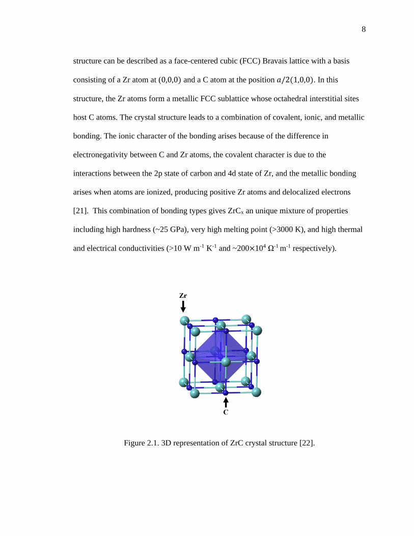
crystallizes in the rocksalt 𝐹𝑚3𝑚 structure (space group 225) [20]. A schematic
representation of the crystalline structure of ZrCx is depicted in Figure 2.1. The crystal
8
structure can be described as a face-centered cubic (FCC) Bravais lattice with a basis
consisting of a Zr atom at (0,0,0) and a C atom at the position 𝑎/2(1,0,0). In this
structure, the Zr atoms form a metallic FCC sublattice whose octahedral interstitial sites
host C atoms. The crystal structure leads to a combination of covalent, ionic, and metallic
bonding. The ionic character of the bonding arises because of the difference in
electronegativity between C and Zr atoms, the covalent character is due to the
interactions between the 2p state of carbon and 4d state of Zr, and the metallic bonding
arises when atoms are ionized, producing positive Zr atoms and delocalized electrons
[21]. This combination of bonding types gives ZrCx an unique mixture of properties
including high hardness (~25 GPa), very high melting point (>3000 K), and high thermal
and electrical conductivities (>10 W m-1 K-1 and ~200×104 Ω-1 m-1 respectively).
Figure 2.1. 3D representation of ZrC crystal structure [22].

9
Zirconium carbide can deviate significantly from its stoichiometric composition
with the formation of structural vacancies in the carbon sublattice. The phase diagram of
the Zr-C system is shown in Figure 2.2. The phase diagram shows the existence of the
ZrCx phase between ~37.5 and 49.5 at.% C, where x is between 0.6 and 0.98, with the
congruent melting of the ZrCx phase at 3723 K. Below ~37.5 at.% C, a hexagonal close
packed Zr and ZrCx coexist field exists until ~1200 K, where the Zr metal becomes body
centered cubic. This phase begins melting at ~2030 K resulting in liquid Zr and solid
ZrCx. For carbon contents higher than 49.5 at.%, a mixture of ZrCx + C phases forms.
Figure 2.2. Calculated phase diagram of Zr-C system. Taken from [20].
As a characteristic non-stoichiometric compound, ZrCx exhibits both short-range
ordering (SRO) and long-range ordering (LRO) for the carbon vacancy distribution [23].

10
Ordered ZrCx phases are usually obtained by long-duration post annealing treatments
[24]. However, vacancy-ordered structures with new symmetry can be also obtained by
direct routes such as high temperature chain–reaction synthesis at ZrC0.6–0.74 [25] or spark
plasma sintering (SPS) of ZrC0.61 nano-powders [26]. The mechanisms driving vacancy
ordering are still largely unstudied. Likewise, accurate phase identification of the
vacancy-ordered variants of ZrCx is difficult in experiments due to the lack of high
quality ZrCx samples and proper characterization techniques [27]. Despite that, the
existence of ordered vacancy configurations is exciting from an engineering standpoint
because it provides the opportunity to fabricate new materials through engineering of
chemical composition and vacancy configurations.
2.2. PROCESSING OF ZIRCONIUM CARBIDE CERAMICS
ZrCx can be produced by solid phase reactions [28], [29], from solution based
precursors [30] , and through vapor phase reaction methods such as chemical vapor
deposition [31], [32]. Various fabrication techniques can provide samples with varying
characteristics including microstructure, chemical composition, and impurity species.
2.2.1. Solid Phase Reaction. Carbothermal reduction of ZrO2 powders with
elemental carbon (Reaction 1) has historically been the most common route to synthesize
zirconium carbide [33], [34]. This method usually requires high temperatures (>1800 ºC)
and long-duration heat treatments (>12 hours) to obtained high purity ZrCx powders.
Furthermore, the reaction requires a strictly controlled environment (vacuum or inert gas)
to ensure purity of the final product. Due to the tendency for carbon deficiencies,
combined with the solubility of oxygen, the carbothermal reduction method often results

11
in the formation of oxycarbide ZrCxOy [28]. The presence of oxygen impurities in the
carbon sub-lattice is known to influence both the densification mechanisms and
thermomechanical properties of the ceramic [35].
ZrO2(s) + 3C(s) → ZrC(s) + 2CO(g) (1)
Alternatively, direct reaction of carbon with Zr [11],[36] (Reaction 2) or ZrH2
[37] (Reaction 3) is used in cases where higher purity or controlled carbon stoichiometry
is desired.
Zr(s) + C(s) → ZrC(s) (2)
ZrH2(s) + C(s) → ZrC(s) + H2(g) (3)
These reactions are classified as combustion synthesis reactions [38]. To produce
the ZrCx powders, the reactant mixture is pressed to form a green body and heated to a
temperature known as the ignition temperature after which the heat released by the
reaction is enough to sustain and drive it to completion. It is essential to maintain the
contact between the reactant particles without which the reaction fails to sustain itself.
Unlike carbothermal reduction route, combustion synthesis methods pose serious
handling issues for bulk production of ZrCx. The limitations are mainly due to the
exothermic nature of the combustion reaction and the size of the zirconium reactant,
which are highly pyrophoric and susceptible to oxidation at room temperatures.
2.2.2. Solution Based Fabrication. ZrCx can also be synthesized by using
precursors via solution-based processing methods [39], [40]. The advantage of using a
solution-based fabrication route is the high intimacy, at a molecular or colloidal scale,
that is achieved between the precursors. This intimate mixing helps to shorten the
diffusion distance, decreasing the heat treatment (dwell temperature and duration)

12
necessary to complete the reaction. The shorter dwell times result in smaller particles
sizes compared with traditional solid-state routes. Sol–gel processing is one of the most
common solution-based routes used for the fabrication of ZrCx powders. Typically, a
polymer containing Zr-O-Zr links is formed from Zr n-propoxide or zirconium
oxychloride and a carbon source such as alcohols or sugar. Pyrolysis then results in
intimate mixing of ZrO2 and C. The production of ZrCx with varying stoichiometry can
be achieved by varying the proportion of the reactant precursors. However, the solution
based mixing process suffers from the disadvantage of residual oxygen impurities.
2.2.3. Vapor Phase Fabrication. Vapor phase reactions are the most common
route to produce ZrCx coatings for microencapsulated nuclear fuel concepts such as the
TRI-structural ISOtropic (TRISO) fuel particles. Given the high melting point of ZrCx
(Tm>3000 ºC), the coatings are normally deposited by low pressure chemical vapor
deposition (LPCVD) [31], evaporation [41], or sputtering [42]. Among these methods,
LPCVD is the preferred one to produce high purity, uniform, and defect-free ZrC
coatings onto TRISO particles [20]. In this process, a Zr precursor is reacted with CH4 in
a fluidized bed reactor at temperatures between 1300 and 1500 ºC. Several zirconium
halides precursors have been used in this process including chloride, iodide, and bromide.
The process can be represented as follows:
ZrX4 + CH4 + 2(1 − x)H2 → ZrCx + 4HX (X = Cl, I, Br, x ≤ 1) (3)
The reaction is conducted in an inert environment to prevent the uptake of oxygen
and other impurities. Also, the C/Zr compositional ratio and the morphology of the
coating can be controlled by varying the flow of methane and hydrogen. Further heat

13
treatments can also be used to adjust the porosity of the coating. Compared to the solid-
state and liquid routes, LPCVD is known to produce high quality ZrCx coatings.
2.3. THERMOMECHANICAL PROPERTIES
Thermal and mechanical properties of ZrCx ceramics at room temperature have
been extensively studied in the last four decades [17],[20], [43],[44], [45], with the most
important properties being strength, hardness, elastic constants, heat capacity, thermal
conductivity, and fracture toughness. Despite these assessments, many fundamental
properties of ZrCx ceramics remain poorly characterized and discrepancies exist among
different studies even in basic properties such as thermal conductivity and strength
(Figure. 2.3). The inconsistencies observed in the thermomechanical database for ZrCx
ceramics is largely attributed to factors such as impurities, vacancies, porosity, and other
microstructural features (grain size, grain boundaries, etc.) that are rarely reported in the
literature. Up to now, most of the studies have reported properties for a single ceramic
without identifying fundamental factors related to composition, microstructure, porosity,
impurities, etc. that can control the observed behavior. Presentation of properties without
an understanding of structure-property relations hinders the reporting of accurate
thermophysical data. Consequently, more systematic studies are necessary to elucidate
microstructure property relationships, isolate fundamental factors that control thermal and
mechanical behavior, and report intrinsic properties of ZrCx ceramics.
The literature survey also indicates that most of the thermomechanical testing of
ZrCx has been conducted under ambient conditions. While insightful, this information is
insufficient to qualify ZrCx as a safe nuclear material for advanced gas-cooled reactors

14
that will operate at temperatures above 600 ºC. Therefore, further experimental work is
required to establish a comprehensive database of the thermal and mechanical properties
of ZrCx at elevated temperatures.
It is necessary to evaluate the thermal and mechanical properties experimentally
because a simple extrapolation of the properties from room temperature to high
temperatures might not take into account potential non-linear behavioral trends, which
could be caused by phenomena such as phase changes, creep, softening of grain
boundary/impurity phases, sub-critical crack growth, or stress-induced microcracking at
high temperature.
Figure 2.3. Thermal conductivity of ZrC as a function of temperature. Taken from [21].

15
Additionally, systematic research on the effects of C/Zr ratio on the elevated
temperature thermophysical properties of ZrCx is needed. A substantial influence of
stoichiometry of ZrCx on elevated temperature properties is anticipated; however, very
limited data is available in this regard.
2.4. MAJOR DEGRADATION MODES
Several environmental degradation mechanisms are encountered in the core of
advanced gas-cooled nuclear reactors including radiation damage and oxidation. A
literature review on the main degradation mechanisms is here presented.
2.4.1. Radiation Damage. Despite having practical knowledge of the
performance of ZrCx ceramics under irradiation conditions, the radiation response
mechanisms of ZrCx are still largely unexplored, with systematic studies only emerging
in the literature within the last two decades. Understanding these mechanisms will allow
for the development of phenomenological and mechanistic models, which can reduce the
number of validation irradiations required in real reactor conditions and provide more
reliable predictions outside of the validation domain. A summary of the historic
irradiation data on ZrCx ceramics is presented in Figure 2.4 [46]. From this figure, it is
clear that most of the studies to date have only focused on the low dose, low temperature
irradiation regime. Although these data has furthered the state of the knowledge about the
radiation response of ZrCx, more research is needed on the effects of neutron and ion
irradiation at high temperatures (>800 ºC) and higher doses (>5 dpa) as these are the
general requirements for materials in advanced nuclear fission reactors.

16
Early studies on the neutron-irradiation behavior of ZrCx, at temperatures ranging
from 300 to 700°C, were reported by Keilholtz et al. [47]. This work investigated the
irradiation response of three types of powder processed ZrCx materials in a strongly
carbon-rich condition (C/Zr ranging from 1.08 to 1.27) and low density (ranging from
70% to 95% theoretical). Although the fabrication routes for each specimen were
described in the paper, the details of the quality of the materials and pre-irradiation
microstructures were not reported. Keilholtz found gross volume swelling (dimensional
changes) in the range of 2–2.7% for three samples.
Figure 2.4. Historic irradiation data on ZrCx compared to operating fuel temperature.
DPA range data is represented by bars, where appropriate, n: neutrons, Kr: krypton ions,
Au: gold ions, P: proton ions. Taken from [46]

17
Reynolds et al. [48] irradiated four experimental fuel particle types based
on zirconium carbide with fast neutrons (E > 0.18 MeV) at 1200 °C up to 5×1021 cm−2.
Post-irradiation examination by stereoscopic, metallographic and electron-
beam microprobe analysis of the irradiated particles indicated that ZrC possesses
exceptional resistance to chemical attack by fission products and good mechanical
stability under irradiation.
Recently, Snead et al. [46] reported the effects of fast neutron irradiation on the
properties of high purity zone-refined ZrC0.87. The samples were irradiated in the High
Flux Isotope Reactor (HFR) at Oak Ridge National Laboratory (ORNL) to fluences
ranging from1 to 10 × 1025 m-2 (E > 0.1 MeV) in the irradiation temperature range of
∼910–1750 K. Small unidentified dislocation loops aligned in a raft-like structure were
observed by TEM analysis in samples irradiated at ∼910 K and a fast fluence
∼4×1025 cm-2. As the temperature increased to ∼1295 K, formation of larger Frank
faulted loops was reported. The microstructure of the samples irradiated at ∼1530 K
contained both distinct Frank loops and other unidentifiable dislocation loops. As the
irradiation temperature increased, a transition from Frank loops to prismatic loops was
reported. The changes in lattice parameter determined by X-ray diffraction were within
the measurement error and the corresponding macroscopic swelling due to lattice
expansion were reportedly less than 0.1%. Though the substantial variation in lattice
parameter in non-irradiated samples prohibited accurate determination of lattice swelling,
the linear lattice expansion appeared to be less than ∼0.03% at all temperatures.
Several studies have conducted proton irradiation of ZrCx at high temperatures.
Yang et al.[49] reported the effect of proton irradiation (2.6 MeV) on the microstructure

18
of ZrC1.01 irradiated to a dose of 0.7 and 1.5 dpa at ∼800 ºC. Post -irradiation
characterization with TEM indicated the formation of high-density nano-sized dislocation
loops with densities increasing with irradiation dose. Yang also reported a change in the
lattice parameter with irradiation dose of 0.09 and 0.11% for 0.7 and 1.5 dpa respectively.
Similar results were obtained by Gan et al.[50] on post-irradiation examination of hot-
pressed ZrC1.01 (∼100% theoretical density) irradiated by 2.6 MeV protons up to 0.71–
1.8 dpa at 800 ºC. Huang et al. [51] investigated the effect of stoichiometry on the
damage evolution in proton-irradiated ZrCx (0.9<x<1.2) up to 3 dpa at 800 ºC. It was
found that the loop size and density were both dependent on dose and stoichiometry. For
substoichiometric compositions, little variation in the diameter of the dislocation loops
was observed for different C/Zr ratios. However, for superstoichiometric compositions,
the defect size and density increased in the vicinity of the graphite precipitates as a
function of carbon content. This suggests that other mechanisms for defect nucleation or
growth may occur in superstoichiometric ZrCx. More research is needed to investigate the
irradiation response of ZrCx in carbon rich regions.
Heavy ion irradiations have been also used to investigate the effects of irradiation
on ZrCx. The seminal work by Gosset et al.[122] reported the microstructural evolution
in hot pressed ZrC subject to 4 MeV Au ion irradiation at room temperature. The ion
fluence was between 1011 and 5×1015cm-2. Three damage stages were identified using a
combination of TEM and XRD analysis. At low fluences (<10 cm-2), no significant
damage to the microstructure and minimal swelling were observed. However, in the
intermediate fluence range (<1014cm-2), formation of high-density dislocation loops and
appearance of microstrain was reported. Swelling saturation (0.6%) was observed at a

19
fluence close to ∼1014 cm-2. With fluences >1015 cm-2, the growth of these loops led to
the formation of a high-density dislocation network via loop interactions. Further
interactions of this dislocation network with defects were cited as the reason for swelling
saturation beyond 1014 cm-2.
Gan et al. [52] irradiated ZrCx with 1 MeV Kr ions to doses of 10 and 30 dpa at
27 ºC, and 10 to 70 dpa at 800 ºC in the Intermediate Voltage Electron Microscope
(IVEM) at Argonne National Laboratory (ANL). Faulted dislocations loops were
observed in all irradiated samples. Irradiations of ZrC to doses of 10 dpa and 30 dpa at
27 ºC caused a 0.7 and 0.9 % lattice expansion respectively. Irradiation at 800 ºC
produced lattice expansion of approximately 0.6% at 10 dpa and 7% at 70 dpa. The large
lattice expansion observed in the sample irradiated to 70 dpa at 800 ºC was attributed to
the formation of precipitate type defect features, which were believed to be face centered
cubic (FCC) ZrC with a lattice constant 8% greater than that of irradiated ZrC. The
formation mechanisms of the nanoprecipitates was not investigated by the authors.
Recently, Ulmer et al. [53] investigated the microstructural evolution of ZrCx
under in-situ ion irradiation conditions using the IVEM at Argonne National Laboratory.
The irradiation response of ZrCx was separated into two different regimes depending on
the irradiation temperature: low temperature (25 ºC and below) and high temperature
(600 ºC and higher). During low temperature irradiation, damage was observed in the
form of black-dot damage. The damage appeared after a threshold dose and increased
gradually with dose until saturation. In the high temperature regime (600 ºC and higher),
ion irradiation resulted in the formation of dislocation loops at doses above 1 dpa.
Gradual coarsening of the microstructure through defect coalescence was observed as

20
dose increased, which led to the formation of entangled dislocation networks at doses
above 5 dpa. Ulmer also observed the formation of nanoprecipitates as a result of Kr
irradiation. The ring pattern of the nanoprecipitates was indexed and was consistent with
a FCC crystal structure with a lattice parameter 8% larger than that of ZrC. No
explanation was provided in this work concerning the formation mechanism of the
nanoprecipitates.
Pellegrino et al. [54], [55] also examined the microstructure of single crystal ZrCx
irradiated with 1.2 MeV Au ions at room temperature. The evolution of the
microstructure as a function of dose was investigated using RBS/C, XRD and TEM
techniques. The results were interpreted in the framework of a two-step damage process
with an increase of the elastic strain in the first step followed by a sharp release of strain
in the second step. accompanied with the appearance of TEM visible damage and large
RSB-C dechannelling The critical dose level for the transition was identified to be 2.2
dpa for Au ions in ZrC. Similar irradiation response has been observed in other non-
amorphizable ceramics such as ZrO2 and UO2.
Computational methods have been also applied to investigate radiation damage in
ZrCx ceramics. Zheng et al.[56] predicted the threshold displacement energy (Ed) of C
and Zr atoms in ZrC using ab initio molecular dynamics simulation. Averaged values of
16 eV and 37 eV were obtained for the C and Zr sublattices respectively. The effect of
the presence of C vacancies on the displacement energies was also investigated. It was
found that a neighboring vacancy can increase the values of Ed, although the increment is
minimal (~4 eV) and only along one crystallographic direction. Jiang et al.[57] used ab
initio molecular dynamics simulations to compare the response of SiC and ZrC to low

21
energy irradiation. It was proposed that the discrepancy in the resistance to antisite
formation between SiC and ZrC contributes to the difference in the irradiation response
of the two ceramics. Zheng et al.[58] used density functional theory methods to
investigate the migration of point defects, recombination of Frenkel pairs (FPs), and
resistance to amorphization in ZrC. They found that interstitials have lower migration
energy than vacancies, and C defects have higher diffusivity than Zr defects.
Additionally, the recombination barrier of C FPs is significantly reduced in the presence
of carbon vacancies and the Zr FP recombination has a low barrier. The amorphization
process of SiC and ZrC was studied by Jiang et al.[59] by adding C Frenkel pairs into
both systems. They found that SiC readily amorphized with the addition of defects in the
carbon lattice but ZrC did not amorphized. This difference was explained in terms of the
intrinsic mechanical instability of the Si sublattice compared with the intrinsic stability of
the Zr lattice. Jiang also reported that regardless of the number of C Frenkel pairs added,
the point defects did not accumulate to enough energy to destabilize the crystalline ZrC.
This behavior suggests that athermal annealing processes are accessible in ZrC with high
concentrations of point defects. Classical molecular dynamics (MD) simulations were
also used by Brutzel et al. [50] to study the primary damage created by collisional
cascade in ZrC. No amorphization was observed in the cascades, and the point defects
created included C and Zr interstitials, a few Zr antisites, and clusters of two kinds of
interstitials.
In summary, the literature review on irradiated ZrCx ceramics shows that ZrCx is
not amorphized by ion and neutron irradiations at temperatures between -253 and 900 ºC.
These experimental observations confirm the superior radiation resistance of ZrCx

22
compared with conventional ceramics such as SiC. The high radiation amorphization
resistance of ZrCx ceramics has been also confirmed by ab-initio computational studies.
Additionally, no evidence of void formation has been reported in neutron and ion
irradiated ZrCx up to doses of 70 dpa and 800 ºC, suggesting that vacancies are sessile
below 800 ºC. TEM analysis of ZrCx irradiated with light and heavy ions at different
temperatures shows that the density of radiation-induced defects decreases with
temperature, indicating that some degree of radiation defect annealing and/or recovery
occurs at higher temperatures. Collectively, these observations indicate that temperatures
between 25 and 800 ºC in ZrCx correspond to temperatures above stage I (onset for
interstitial motion) and below recovery stage III (on-set temperature for vacancy motion).
This temperature regime is also known as the “point defect swelling” regime and is
characterized by the accumulation of radiation damage until saturation is reached at doses
between 0.1 and 1 dpa. The damage saturation is due to the high concentration of
immobile vacancies that serve as recombination centers for the migrating
interstitials [12].
2.4.2. Chemical Compatibility with Coolant. In advanced high temperature
gas-cooled reactors, helium gas will be used as a primary coolant. Under normal
operation conditions, the helium gas will inevitably contains part per million (ppm) levels
of impurities such as CO, CO2, H2, H2O, O2, and CH4, which arise mainly from in-
leakage of O2, N2 and water vapor from seals and welds, and degassing from reactor
materials. Depending on the level of impurity concentration, temperature, and material
composition, the impurities can react with in-core structural components resulting in a
variety of corrosion reactions. Given the high chemical affinity of ZrCx towards oxygen

23
and water vapor impurities, it is possible that in-service oxidation of ZrCx components
occurs under normal operation in advanced high temperature gas-cooled reactors. While
the oxidation of ZrCx has been extensively studied in non-nuclear contexts, issues that are
unique to the reactor environment are the effects of radiation on the oxidation of ZrCx. To
the best of our knowledge, no previous studies have investigated the oxidation of ZrCx
under prototypical operation conditions of high temperature gas-cooled reactors.
Consequently, new experiments need to be conducted to achieve a comprehensive
understanding of the in-service oxidation mechanisms of ZrCx and its impact on the
material performance. A detailed knowledge of the oxidation mechanism and rates of
microstructure degradation is also important to estimate the lifetime of the components
and define mitigation strategies.
2.4.3. Air Ingress Accident. An air ingress-accident is one of the design basis
accidents (DBA) of high temperature gas-cooled reactors [60]. This accident is initiated
by a break in the hot duct of the reactor core vessel and can lead to an initial loss of the
primary helium coolant by depressurization. Following the depressurization process, the
air-helium mixture in the reactor cavity could enter the reactor core producing oxidation
of the core components. The air ingress event can last for hours or days, depending on the
severity of the accident, and cause the reactor core to become immersed in air atmosphere
at temperatures around 1600 ºC [61].
A literature survey on the oxidation behavior of ZrCx indicates that it is
vulnerable to oxidation and the rate of this process depending on temperature, porosity,
partial pressure of oxidative and reductive gas species, carbon content, and
impurities [95], [96], [97], [98]. Although it is well established that oxidation does not

24
affect ZrCx at room temperature, complete spalling can occur due to oxidation at elevated
temperatures (T > ∼870 K), especially in high oxygen partial pressure environments
(∼130 kPa) [94], [97], [98]. However, at temperatures exceeding ∼1500 K with sufficient
oxygen partial pressures, ZrC is known to passivate and the produced zirconia undergoes
limited yet considerable sintering contributing to improved structural integrity in certain
conditions [96]. The mechanisms of oxidation of ZrC at temperatures above 470 ºC is
explained with the following steps:
• The formation of ZrOxCy, which proceeds to form amorphous ZrO2 and C
upon oxygen saturation. The formation of oxycarbide is well expected as oxygen is
known to dissolve in ZrCx [62]. The rate of oxycarbide formation is controlled by the
phase boundary reaction, especially with oxygen partial pressure ∼100 kPa [63], [64]. At
temperatures below 600 ºC, with low oxygen partial pressures (<50 kPa), the literature
supplies evidence of the presence of zirconia and free carbon in the scales [65], [66]. The
overall reaction is summarized by [65].
ZrC +1
2(1 − x)O2 → ZrCxO1−x + (1 − x)C (4)
ZrCxO1−x +1
2(1 + 3x)O2 → ZrO2 + (x)CO2 (5)
• As the temperature increases (>600 ºC), cubic zirconia begins to nucleate
from the amorphous zirconia and the crystals start to grow. The stabilization of the c-
ZrO2 polymorph occurs via substitution of O2- with C3-ions creating oxygen vacancies.
• Oxygen then diffuses through this oxide layer to the free carbon producing

25
CO2 with diffuses out via existing pores or cracks, leaving behind pores in the zirconia
layer, which with very little carbon left to stabilize transform to monoclinic zirconia (m-
ZrO2), along with small amounts of tetragonal polymorph (t-ZrO2).
• With further increase in the temperature beyond 800 ºC, the stress exerted by
the growth of m-zirconia at the grain boundaries and the pressure exerted by the
increased CO2 gas initiates inter-crystalline fracture in an already porous layer [67]. In
the range of temperature between 800 and 1100 ºC, the oxidation behavior of ZrC is quite
complex as summarized schematically in Fig 2.5. The oxide formed by oxidation at
below 900 ºC strongly adhere to the carbide core and is comprised of m‐ and t/c‐ZrO2
[68]. On the contrary, the oxide scale formed at temperature above 1100 ºC shows a gap
between ZrC and ZrO2−x and the oxide was voluminous and made of m‐ZrO2. The
voluminous and heavily cracked structure of the oxide at 1100 ºC demonstrates its
nonpassivating nature at this temperature range.
• With temperatures above 1200 ºC, the porous zirconia scale (mostly m-ZrO2)
starts to sinter and densify, acting as a barrier for the diffusing oxygen atoms [67]. Then
the CO2 partial pressure assumes control of oxidation rate as the gas starts to effuse out of
the shrinking pores. With most of the paths for oxygen to reach the ZrC substrate blocked
by CO2 and densification of the scale, oxidation turns passive as long as the zirconia scale
remains intact. The sintering process also ensures structural stability of the ZrC coating
and prevents it from spalling, with considerable reduction in inter-crystalline
stresses [67], [69].
Despite the numerous studies on the oxidation behavior of ZrCx [70],[71], [72], a
clear understanding of this process has not been achieved yet. due to the large numbers

26
of variables that affect it, such as chemical composition of the initial material (C/Zr
stoichiometry), porosity, or grain size [20], [73]. Additionally, most of studies published
until now have only investigated the out-of-pile oxidation of ZrC at temperatures relevant
to reactor operation. Thus, these studies suffer from major limitations as they do not
consider the radiation effects that occur in nuclear reactors. Radiation can affect the
oxidation behavior of ZrCx in a number of ways. For example, the interaction between
ionizing radiation and coolant impurities can produce a variety oxidizing species that
could accelerate the oxidation through an increase in oxidation potential. Likewise, the
oxidation rate can be affected by the properties of the oxide layer formed during
exposure, including oxide morphology, oxide phase, stress, etc. In the oxide, the
displacement of ions from their lattice sites by radiation could lead to enhanced point
defect concentrations, enhanced diffusion, which would lead to accelerated oxidation.
These mechanisms need to be understood in order to predict the oxidation performance of
ZrC in nuclear environments.
Figure 2.5. Stages of the oxidation of hot‐pressed (H.P.) specimens of ZrC at 800
and 900 ºC in atmospheric air. Taken from [68].

27
2.4.4. Other Degradation Mechanisms. There are other degradation mechanisms
that are important for the implementation of ZrCx in nuclear reactors such as the chemical
interaction with fission products. This topic is beyond the scope of this thesis and will not
be further elaborated. An extensive review on retention of fission products in ZrC-based
fuels have been recently published by Katoh et al. [20].

28
PAPER
I. THE ION- IRRADIATION RESPONSE OF ZrC CERAMICS AT 800 ºC
Raul Floreza, Miguel L. Crespillob, Xiaoqing Hec,d, Tommi A. Whitec,e, Gregory Hilmasf,
William Fahrenholtzf, Joseph Grahama,f*
a. Nuclear Engineering Program, Missouri University of Science and Technology,
65409 Rolla, MO, United States
b. Department of Material Science and Engineering, University of Tennessee, 37996
Knoxville, TN, United States
c. Electron Microscopy Core, University of Missouri, 65211 Columbia, MO, United
States
d. Department of Mechanical and Aerospace Engineering, University of Missouri,
65211 Columbia, MO, United States
e. Department of Biochemistry, University of Missouri, Columbia, MO, 65211,
United States
f. Department of Materials Science and Engineering, Missouri University of Science
and Technology, 65409 Rolla, MO, United States
ABSTRACT
The microstructural evolution was characterized for ZrC ceramics irradiated with
10 MeV Au3+ ions at 800 ºC. Post-irradiation examination showed that ZrC did not
amorphize at doses up to 30 displacement per atoms (dpa). Concurrent oxidation of ZrC
was found to occur during ion irradiation. Coarsening of the defective microstructure, as a
function of dose, was revealed by transmission electron microscopy analysis. Black dot

29
defects were observed at low doses (0.5 dpa), and tangled dislocation networks were
formed at 5 dpa and above. Diffraction analysis showed a change in the defect structure
occurred at doses close to ~2.5 dpa. The evolution of lattice parameter with dose indicated
that uptake of adventitious oxygen could occur in specimens irradiated at high doses.
Raman spectroscopy analysis indicated an increase in non-stochiometry after irradiaton.
This work identified specific relationships between dose and microstructure after
irradiation, revealing the mechanisms of damage production in ZrCx ceramics.
Keywords: Ion Irradiation, ZrCx, XRD, TEM, Raman
* Corresponding author
Email: [email protected]
1. INTRODUCTION
Zirconium Carbide (ZrCx) is a ceramic material that exhibits high melting
temperature and Vickers hardness [1], excellent high-temperature thermal and
mechanical properties [2], adequate corrosion resistance to fission products [3], [4], and
low neutron absorption cross section[1], [5]. This unusual combination of properties
makes ZrC an attractive candidate for a variety of elevated-temperature nuclear
applications, including fuel cladding and inert fuel matrix materials for Gen-IV gas-
cooled reactors [6], [7], structural components in fusion reactors [8], and as a coating in
Trisostructural-Isotropic (TRISO) fuel particles [9-12]. In these applications, ZrCx would
be exposed to neutron and ion irradiations [13],[14]. As a result, atomic defects, lattice

30
disorder, and other radiation-induced microstructural modifications are expected to occur
due the substantial amount of energy deposited in the target material under irradiation.
The formation and distribution of radiation-induced defects can significantly affect the
mechanical, thermophysical, and chemical properties of ZrCx after irradiation [15-17].
Consequently, successful implementation of ZrCx in nuclear systems requires
investigation of its radiation response mechanisms and the concomitant radiation
effects on the properties.
During the last three decades, a great number of experimental [18-22] and
theoretical investigations [23-26] have been dedicated to understanding the fundamental
processes that govern the radiation response of ZrCx. The majority of studies to date have
focused on characterizing the radiation damage produced by nuclear elastic interactions
(i.e. ballistic damage), which is most relevant to the operational performance of ZrCx
subject to neutron fluxes in nuclear reactors [27].To this end, intermediate-energy heavy
ions and protons from ion accelerator facilities have been widely used to emulate ballistic
damage under well-controlled irradiation conditions and high displacement doses [28].
Ballistic collisions displace atoms from their equilibrium positions, initiating a series of
structural changes within the target material, which are dependent on the rate of
production, annihilation, and agglomeration of the radiation-induced point defects at a
given temperature [29]. Using this approach, systematic studies have been conducted for
ion irradiation of ZrCx at multiple irradiation conditions over the temperature range of
20-1073 K [30-32]. The ion irradiated microstructures have been characterized with a
number of techniques including transmission electron microscopy (TEM) , X-ray
diffraction (XRD), ion channeling Rutherford backscattering spectrometry (RBS/c), and

31
Raman spectroscopy. No amorphization has been observed in any of the above studies,
demostrating the superior structural stability and radiation tolerance of ZrCx over the
temperature range investigated.
Previous studies suggested that within the operational temperature range of high
temperature nuclear reactors (600-1100o C), the radiation response of ZrCx is driven by
interstitial clustering [33]. Due to the high melting point of ZrC (Tm=3420 oC [34]),
vacancy mobility is not expected when Tirr<0.3Tm. In contrast, interstial atoms are highly
mobile even at RT and immediately tend to cluster to form dislocation loops under far
from equilibrium conditions [26]. These observations have been validated experimentally
by TEM anlaysis, through which “black dot” defects and dislocation loops have been
observed as the primary type of defects in irradiated ZrCx [13], [31], [32], [35]. The
clustering of interstitials in irradiated ZrCx has also been reproduced numerically using
DFT-informed Cluster Dynamic simulations [33]. In the low homologous temperature
regime, where interstials are mobile and vacancies are sessile, two competing process
occur simultaneously: dislocation loop nucleation and interstitial capture by dislocation
loops. Initially at lower doses (~ <1 dpa), the rate of nucleation of interstitial clusters
outpaces the rate of loop growth because the density of dislocation loops is low. When
increasing the irradiation dose, new interstital clusters are more likely to coalesce with
each other to form dislocation loops. These loops will continue to grow in size and
density until a critical dose is reached. At this point, the rate of dislocation loop
nucleation is reduced because the defect clusters generated by irradiation are more likely
to coalesce with the already nucleated dislocation loops. Consequently, irradiation
beyond this threshold dose will produce coarsening of dislocation loops that are already

32
formed. As dislocation loops grow, each will become an increasingly larger sink for
defects, so the nucleation rate of loops should continue to drop until saturation is reached.
As a result, a saturation in the density of dislocations is also expected with the increase in
the irradiation dose.
Although a coarse understanding of the radiation response of ZrCx can be drawn
from the existing literature, more studies are needed to complement the previously
reported experimental data and provide a comprehensive understanding of the
performance of ZrCx within the typical temperature (600-1100o C) and dose range (0.5-50
dpa) of high temperature nuclear reactors (HTRs) [36]. In this regard, only a limited
number of studies have been conducted on high-temperature ion irradiation of ZrC at
high doses. Moreover, knowledge of the radiation response of ZrCx ceramics at different
length scales is still scarce. This information is particularly relevant for future fission
Gen-IV reactors and fusion reactors which require materials to reliably operate at higher
temperatures and/or radiation damage levels than those of existing commercial power
reactors [37].
The purpose of the present study was to investigate the microstructural evolution
of heavy ion irradiated ZrCx at dose and temperature conditions relevant to the operation
of high temperature nuclear reactors.

33
2. EXPERIMENTAL PROCEDURE AND METHODS
2.1. SAMPLE PREPARATION
ZrC billets were prepared by the hot pressing commercial ZrC powder (Alfa
Aesar, Reactor Grade, USA), which had a reported purity of 99.5 wt%, (impurities
(wt.%): Al 0.01, Hf <0.003, Ti 0.009, Cd 0.0002, Cr 0.0003, Mg 0.0006 , Pb 0.002). The
billets were hot pressed in a graphite die (diameter=25 mm) using cylindrical graphite
spacers (thickness=10 mm). The inner walls of the die and the faces of the spacers were
lined with a BN-sprayed graphitized foil to prevent a reaction between the powder
compact and the graphite die. ZrC powder was loaded into the die and cold-compacted
using a uniaxial press with an applied pressure of 4 MPa. The die was then placed into a
resistively-heated graphite hot press (Model HP20-3060, Thermal Technology Inc., Santa
Rosa, CA). Once loaded into the hot press, the chamber was evacuated and backfilled
with argon three times. Billets were hot-pressed at 2200oC and 32 MPa for 2 hours to
promote full densification. A heating rate of 200C/min was used.
The density of the hot-pressed billets was measured by Archimedes’ method
using distilled water as the immersing medium, according to ASTM C73 [38]. The
relative density was calculated by dividing the Archimedes’ density by the estimated
theoretical density of ZrC.
Following densification, specimens for microscopy and ion irradiations were cut
parallel to the hot-pressing direction of the billet with a slow-speed diamond saw and
then ground and polished to mirror-finish. The metallographic preparation was carried
out by grinding the specimens with 100, 320, 600, and 1200 grit SiC pads and water

34
lubricant. Felt pads and water-based diamond slurry suspensions were used for abrasive
sizes from 3 µm to 0.025 µm. After polishing, the specimens were ultrasonically cleaned
with ethanol for 15 minutes at room temperature.
2.2. ION IRRADIATION
A rectangular ZrC polished section (13 x 8 mm) was irradiated in the Ion Beam
Materials Laboratory (IBML UT-ORNL) at the University of Tennessee, Knoxville [39]
with 10 MeV Au3+ ions at 800o C using a 3.0 MV tandem accelerator. Five different
regions of the ZrC specimen (3x3 mm each) were irradiated to doses of 0.5, 2.5, 5, 10 and
15 dpa. The total sample area was thus comprised of the five non-overlapping irradiated
regions and one unirradiated control region. An additional ZrC polished section was also
irradiated to a dose of 30 dpa at the same temperature. Adjustable beam slits were used to
define the irradiation areas. The ion beam was defocused and rastered in the horizontal
and vertical directions with the aim of producing a region that was homogeneously
irradiated. Beam homogeneity was verified by ion-induced luminescence from quartz
targets and was found to be within 10% throughout the irradiated area [40]. The flux was
set at 1.0 ×1012 cm-2 s-1 for all fluences. Low beam current densities in the range of 5 nA
mm-2 were used to reduce any undesired effect and charge accumulation on the samples
[41]. The vacuum chamber pressure was observed to be below 5 ×10⁻⁸ torr prior to the
sample heating process. During sample heating, the chamber pressure initially rose before
decreasing to a range of 3-5 x10⁻⁷ torr during irradiation. The maximum outgassing of
the specimen was observed around 170o C with vacuum pressure levels of 7.8 x 10⁻⁶ torr.
The Stopping and Range of Ions in Matter binary collision approximation (BCA) code

35
2013 version (SRIM-2013) [42] was used to estimate the displacement damage depth
profile. Cascades were performed in quick-cascade mode (simple Kinchin and Pease
model), assuming a target density of 6.71 g/cm3 and threshold displacement energies of
37 eV for Zr and 16 eV for C. To compare ion and neutron irradiation results, the use of
the quick Kinchin–Pease option in SRIM to compute radiation damage exposure has been
recommended [43] within the nuclear community and has been widely used in previous
studies of ion-irradiated ZrC [35], [18], [19]. The damage profile estimated from SRIM is
determined by the sum of the predicted vacancy concentrations (using 'Knock-Ons' from
Au ions and 'Vacancies' from target elements of Zr and C), together with the replacement
collisions [44]. Assuming a bulk ZrC sample, the predicted damage profile in
displacements per atom (dpa), and the implanted Au ion profile, are shown in Figure 1.
The peak dose under 10 MeV Au irradiation is located around 1000 nm. The conversion
factor from ion fluence (1014 cm−2) to local dose in the ZrC foil under quick simulation
was 0.8343 dpa. The steady state temperature of the sample surface was measured via a
K-type (chromel-alumel) thermocouple (TC). The TC was attached to the sample surface
by molybdenum spring-loaded clips. Samples mounted on the high temperature stage
were conductively heated from the platen. The rear of the platen was radiatively heated
using a resistively heated tungsten filament (ERH series heater and EPS-500 power
supply, Thermionics Northwest, Inc.). High performance silver paste was used to
improve the thermal contact between the bottom surface of the sample and the platen.
More details on the experimental apparatus are provided elsewhere [39],[41]. Irradiations
were performed with Au ions because of their relatively inert nature and large nuclear
stopping cross section, which produces a high damage rate per incident ion and

36
minimizes artifacts induced by the injected ions. It is worth noting that a 10 MeV energy
beam was chosen to obtain a relatively flat profile to a depth of 1 µm without appreciable
effects of implanted Au ions (Figure 1). Moreover, intermediate energy heavy ion
irradiations produce a displacement cascade density and morphology more similar to
fission neutrons than light ion irradiation, which produce a more space sub-scale
morphology [45]. The temperature and range of doses were selected with the goal of
studying radiation damage mechanisms and their effects on microstructural evolution and
physical property changes in Gen-IV high temperature gas-cooled reactors [37] .
2.3. MATERIAL CHARACTERIZATION
In this section, the different experimental techniques and methods that were used
for material characterization of the specimens are described.
2.3.1. Grazing Incidence X-Ray Diffraction (GIXRD). Grazing incidence X-ray
diffraction measurements were performed to evaluate structural modifications in the near
surface region following high temperature ion irradiations. GIXRD profiles were
collected on a PANanlytical X’Pert Pro Multipurpose Diffractometer (MPD) fitted with a
Cu X-ray tube and an X’Celerator detector. Diffraction patterns were acquired in grazing
incidence geometry over the 2θ range 25-900 with a step size of 0.030 and counting time
of 0.5 s at each step. The scans were recorded at several incident angles between 0.5 and
50 in order to probe microstructural changes at different depths from 0.6 to 1.5 µm
(Figure 2). X-ray tube operation conditions were 40 kV and 40 mA. The lattice parameter
was refined by Rietveld analysis in the full matching pattern mode with the Fullprof suite
software [46].

37
2.3.2. Line Profile Analysis. The values for the size of coherent diffracting
domains and microstrains were determined using Williamson-Hall analysis. Peaks
obtained from only Cu kα1 radiation were analyzed after stripping Cu kα2 peaks using the
classical Rachinger’s method [47]. Instrumental broadening was described using a
Caglioti polynomial expression obtained by line profile fitting of LaB6 standard powder
(SRM 660a) over the 2θ range investigated. The instrumental integral broadening, thus
defined, was subsequently subtracted from the measured integral breadth of the samples
to obtain the structural line broadening 𝛽.
The coherent diffracting domain sizes (𝐷𝑣) and microstrains (𝜀) were obtained
from the ordinate intercepts and the slopes, respectively, of straight lines in the
Williamson–Hall plots, according to the following equation:
𝛽 cos(𝜃) = 𝜆
𝐷𝑣+ 4𝜀 sin(𝜃) (1)
where 𝛽 is structural line broadening of the reflection, 2𝜃 is the peak position angle, and
𝜆 is the monochromatic x-ray wavelength.
2.4. ELECTRON MICROSCOPY
Surface morphology and composition were examined for both pristine and
irradiated materials by focused ion beam (FIB)-scanning electron microscopy (FIB SEM,
SciosTM DualBeamTM, FEI, Hillsboro, Oregon) coupled with energy dispersive
spectroscopy (EDS; Oxford Instrument Avignon UK). TEM specimens were also
prepared using the focused-ion-beam (FIB) lift-out technique. Before milling, a 2 µm
thick Pt layer was deposited on the top surface of the specimen to protect it from ion
beam-induced damage and unwanted surface milling during the FIB preparation. The

38
trenching on both sides was performed at an ion beam voltage of 30 kV with a beam
current of a few nanoamps. After lift-out, thinning of the lamella was first conducted
with a beam current of hundreds of picoamps at 30 kV at 5 on both sides using
cleaning cross-section mode until the lamella was ~1 m thick. Voltages and currents
were gradually reduced, and the milling angles decreased, as the lamella got thinner.
To complete the preparation, gentle polishing with Ga+ ions (5 keV and 48 pA) at 7 in
regular rectangular mode was used to reduce damage and artifacts of ion implantation
caused by higher energy Ga bombardment. Microstructure characterization was
performed using a 300 kV Tecnai F30 Supertwin transmission electron microscope
(TEM). Bright field (BF) images were acquired under a 𝑔 = 𝟐𝟐𝟎 two beam condition
with the deviation vector s being slightly positive.
2.5. RAMAN SPECTROSCOPY
Raman measurements were collected using a HORIBA Jobin Yvon LabRAM
ARAMIS microRaman spectrometer (Horiba, Edison, NJ). The specimens were excited
by a 632 nm He/Ne laser focused to a spot 2-3 µm in size on the sample using a 50x
microscope objective lens. Raman spectra were acquired in the backscattering geometry.
The laser power was below 2 mW to prevent local heating of the sample. Five spectra
were taken from each specimen, with all measurements conducted at room temperature.
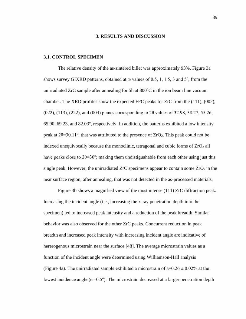
39
3. RESULTS AND DISCUSSION
3.1. CONTROL SPECIMEN
The relative density of the as-sintered billet was approximately 93%. Figure 3a
shows survey GIXRD patterns, obtained at ω values of 0.5, 1, 1.5, 3 and 5o, from the
unirradiated ZrC sample after annealing for 5h at 800oC in the ion beam line vacuum
chamber. The XRD profiles show the expected FFC peaks for ZrC from the (111), (002),
(022), (113), (222), and (004) planes corresponding to 2θ values of 32.98, 38.27, 55.26,
65.90, 69.23, and 82.03o, respectively. In addition, the patterns exhibited a low intensity
peak at 2θ=30.11o, that was attributed to the presence of ZrO2. This peak could not be
indexed unequivocally because the monoclinic, tetragonal and cubic forms of ZrO2 all
have peaks close to 2θ=30o; making them undistiguahable from each other using just this
single peak. However, the unirradiated ZrC specimens appear to contain some ZrO2 in the
near surface region, after annealing, that was not detected in the as-processed materials.
Figure 3b shows a magnified view of the most intense (111) ZrC diffraction peak.
Increasing the incident angle (i.e., increasing the x-ray penetration depth into the
specimen) led to increased peak intensity and a reduction of the peak breadth. Similar
behavior was also observed for the other ZrC peaks. Concurrent reduction in peak
breadth and increased peak intensity with increasing incident angle are indicative of
hererogenous microstrain near the surface [48]. The average microstrain values as a
function of the incident angle were determined using Williamson-Hall analysis
(Figure 4a). The unirradiated sample exhibited a microstrain of ε=0.26 ± 0.02% at the
lowest incidence angle (ω=0.5o). The microstrain decreased at a larger penetration depth

40
probed using ω=1, 1.5, 3 and 5o, suggesting that the region of highest strain is localized
within the first 20 nm of depth from the top surface. The main sources of microstrain
could be the difference in the molar volume and thermal expansion coefficient between
the major phase, ZrC, and the minor phase of ZrO2 that was detected; although some
residual microstrain could have been introduced during polishing steps used to prepare
the surfaces that were irradiated.
The formation of the oxide phase near the surface of the annealed ZrC was
confirmed by SEM observations (Figure 5). Annealing produced discrete nanosized
nodules distributed across the surface of annealed specimen that were not present in the
original polished surface. The nanoprecipitates ranged in sizes between 20 and 100 nm.
Energy dispersive spectroscopy (EDS) analysis indicated that Zr, C and O were the major
constituents on the top surface area of the annealed sample This suggests that the
nanoprecipitate nodules observed in the SEM images correspond to the nuclei of the
oxide phase detected by GIXRD measurements. Some precipitate-free zones were
observed near the grain boundaries of the substrate, which were also revealed due to
thermal etching during annealing.
Further analysis of the (111) ZrC reflection (Figure 3b) revealed that the location
of the diffraction maxima shifted to higher 2θ angles as ω decreased. This suggests that
the lattice parameter of ZrC was lower near the surface (Figure 4b), which could arise
from dissolution of adventitious oxygen into the ZrC lattice during annealing. Oxygen
uptake result, which is sometimes described as the formation of an oxycarbide (ZrCxOy)
compound, does not change the structure of ZrC, but decreases the lattice parameter [49].
The contraction of the unit cell results from the strengthening of the metal-non-metal

41
bonds upon incorporation of oxygen into vacant sites in the unit cell [50]. This agrees
with the previous work by Gendre, who showed the lattice size of ZrC decreased with
oxygen content up to a stoichiometry of around ZrC0.79O0.13 [51].
3.2. IRRADIATED SPECIMENS
Next, the results of the GIXD, TEM and Raman spectroscppy analyses for the
ion-irradiated samples are presented.
3.2.1. GIXRD and TEM Analysis. Figure 6a shows representative GIXRD
patterns of ZrC samples after irradiation with 10 MeV Au3+ at 800oC. The diffraction
patterns were acquired at ω=1.5o to probe a suitable artifact-free midrange region of the
implantation profile (see Figure 2). Similar to the control specimen, the main peaks
indexed to ZrC, and low intensity ZrO2 peaks were observed at 2θ=30.11o for the
irradiated specimens. Upon irradiation, three major changes were observed in the XRD
patterns: shifts of the diffraction maxima, peak broadening, and reduction in the
intensities. No evidence of amorphization was observed in any of the samples irradiated
at 800oC, confirming the outstanding stability of ZrC under irradiation. Similar results
have been previously reported in neutron and ion irradiation experiments of ZrC at both
room temperature and high temperature [30], [31], [32]. The most obvious effects of
increasing the irradiation dose are a decrease in ZrC peak intensity and an increase in
peak broadening. These changes occur due to the microstructural distortions and
heterogeneous microstrain associated with the formation of radiation-induced defects. In
this regard, the defects present in the irradiated materials distort the long range symmetry
of the ideal rock-salt crystal structure, resulting in a partial loss of the coherent scattering

42
and the concomitant decrease in peak intensity. On the other hand, the increased peak
broadening can also be ascribed to the accumulation of heterogeneous microstrain and/or
the reduction of the coherent scattering domain size.
Williamson-Hall analysis was applied to irradiated samples. W-H plots for the
irradited samples are shown in Figure 7(a). With the exception of the specimen irradiated
to 2.5 dpa (Figure 7b), no anisotropic peak broadening was observed along any specific
crystallographic direction in the diffraction pattern of the irradiated samples. The strong
peak broadening anisotropy at 2.5 dpa was accompanied by an increased diffuse
scattering and a signifcant reduction of the peak intensity. These concurrent changes are
indicative of an increased atomic disorder, which could be due to point defects and
dislocation loops. The scattering of X rays from point defects and clusters contribute to
diffuse scattering very close to the Bragg peak, which is known as Huang scattering [52].
This type of scattering can be evaluated to analyze the defects in the irradiated sample;
however, the GIXRD measurements in this study were conducted at room temperature
and the Huang scattering near the Bragg region is superimposed by thermal diffusion
scattering, making its evaluation difficult. Since the W-H analysis for the sample
irradiated to 2.5 dpa was confounded by these other effects, this specimen was not
considered in the subsequent line-broadening analysis. The W-H plots indicated that
grain size did not change significantly, but strain increased with increasing dose. This
indicates that the XRD peak broadening is primarily due to strain, rather than a reduction
in grain size. The average microstrain values for the irradiated samples obtained are
shown in Figure 8(a). It is noted that the average microstrain increased with the
irradiation dose and then saturated at doses above 5 dpa with 𝜀𝑠𝑎𝑡 ~2.2 × 10⁻³.

43
Saturation of the dislocation density at high doses could explain the microstrain
trend observed in this work. At low doses (0.5 dpa), the radiation-induced interstitial
clusters have sizes in the order of a few nanometer (< 5 nm) and their density is low.
Therefore, the microstrain value observed at 0.5 dpa is also low (~1.2 × 10⁻³). Figure 9a
shows an on-zone axis bright field TEM micrograph of the sample irradiated at 0.5 dpa.
The image reveals the presence of “black dot” defects, which are likely to be small
interstitial clusters formed by the ion irradiation. No dislocation loops, with or without
double arc-contrast, are observed in the micrograph. Similar results have been obtained in
previous TEM work of ion irradiated ZrC at low doses and high temperatures [30], [35].
On the other hand, at doses higher than 5 dpa, it can be hypothesized that ZrC has already
reached the saturation point in the coarsening-dominant regime. In other words, the rate
of dislocation loop nucleation has dropped to a steady state value ,and therefore the
radiation-induced dislocation structure does not undergo further coarsening. This
hypothesis is consistent with the previous in-situ TEM study by Ulmer et al. [35], which
noted that the microstructure of ZrC, irradiated with 1MeV Kr ions at 800oC, continued
to coarsen until doses of 5.1–7.7 dpa. Beyond this dose, a tangled dislocation network
formed, and little change was observed in the irradiated microstructure. In this work,
“cellular-like” dislocation networks were also observed in bright-field (BF) images of the
irradiated microstructure at doses above 5 dpa (Figure 9b and c). This suggests that at
high doses (>5 dpa), a balance was reached between irradiated-induced damage buildup
and dynamic annealing of defects at 800oC.
Figure 8b shows the evolution of the ZrC lattice parameter as a function of the
dose obtained by refinement of the peak shifts in the XRD patterns. Interestingly, the

44
evolution of the unit cell parameter in this study is not consistent with a single impact
mechanism for damage accumulation. This result differs from previous observations by
Gosset et al. [53], who reported a saturation of the cell parameter evolution for ZrC
irradiated with 4 MeV Au ions at room temperature. In the present study, the unit cell
parameter of ZrC exhibited a complex, non-monotonic behavior as a function of dose.
Initially, the unit cell parameter increased until reaching a dose of 2.5 dpa. Then, above
this critical dose, the lattice parameter decreased. The recovery of the unit cell parameter
is consistent with a two-step damage accumulation process, which has been previously
observed in single crystal ZrC and other non-amorphizable ceramics under irradiation in
the nuclear energy loss regime [54], [55] . According to this mechanism, a build-up of
elastic strain is observed at the early stages of the damage process due to the production
and clustering of Frenkel Pair (FP) defects. The accumulation of FPs leads rapidly to the
formation of dislocation loops that continue to grow in size as the dose level is increased.
Eventually, at the thresold dose, the dislocation loops come into contact with each other
and form an entangled dislocation network. This transformation in the defect structure is
accompanied by an elastic strain relaxation due to the plastic deformation associated with
the production of extended defects. According to Pellegrino et al [33], the critical fluence
for this transition is about 5×10¹⁸ ions/m2 (~2.2 dpa) for Au ions in ZrC. This value is
close to the transition dose for unit cell parameter recovery that is observed in this work.
However, another explanation will be required to account for the reduction of the unit
lattice parameter at higher doses, where the structure of the dislocation network is no
longer coarsening.

45
One possible explanation for the decrease of the lattice parameter at high doses
could be the uptake of adventitious oxygen during the irradiation process. As mentioned
above, the incorporation of oxygen into the crystaline structure of ZrC is accompanied by
a contraction of the unit cell parameter. Zirconium carbide is well known for its high
chemical sensititivity to oxygen impurities. Although the ion irradiations in this study
were conducted in high vacuum conditions (<10-6 Pa), some residual oxygen and other
hydrocarbon impurities are present in the irradiation chamber [56]. These impurities
could oxidize target materials that are oxygen-sensitive during ion irradiation studies.
ZrC has been reported to be subject to radiation-enhanced or radiation-induced oxidation
at room temperature, even under vacuum (on the order of 10-6 Pa) [53]. Oxygen
enrichment has also been observed in ZrC implanted with argon and xenon ions [57],
[58]. In the present work, the formation of ZrO2 phases in the irradiated samples was
supported by GIXRD measurements at low incident angles. Based on these findings, it is
possible that the diffusion of oxygen atoms may be enhaced during the high temperature
irradiation of ZrC. Radiation enhanced diffusion (RED) is assisted by a linear
superposition of different possible diffusion paths, such as monovacancies, divacancies,
and dislocation lines, among others. These diffusion pathways can facilitate the ingress of
oxygen atoms into the implantation layer, producing an oxycarbide compound that is
isostructural with ZrC. Gosset et al. [18] investigated the influence of oxygen content on
the radiation response of ZrC. They found that ZrC and ZrOxCy compounds follow the
same type of microstructural evolution under radiation conditions, with oxycarbides
showing a delay in the saturation fluence with respect to carbides. At high doses, such as
those used in this study, entangled dislocation networks and vacancies may favor the

46
dissolution of oxygen into ZrC. However, the exact mechanism of oxygen uptake under
irradiation conditions remains to be elucidated in future work.
3.2.2. Raman Spectroscopy. Figure 10 shows the Raman spectra of the control
and irradiated samples. The spectra exhibit four predominant Raman bands centered
around 200, 275, 515, and 600 cm-1. These spectra are very similar to those obtained in
single crystals of ZrC with sub-stoichiometric compositions [59], [60]. The first-order
Raman spectrum in ZrC1-x has been attributed to the presence of carbon vacancies that
destroy the local inversion symmetry of the ideal NaCl rock-salt structure, enabling
defect-induced Raman scattering to be observed. The vacancy-induced first-order Raman
spectrum resembles the phonon density of states (DOS) in ZrC. The low frequency
Raman peaks (transverse acoustic ~204 cm-1 and longitudinal ~275 cm-1) are produced by
acoustic phonons, while the high frequency peaks (transverse optic ~515 cm-1 and
longitudinal optic ~600 cm-1) are due to optical phonons.
A comparison of the unirradiated and as-irradiated spectra shows that the Raman
peaks associated with vacancy defects became more intense and broader when increasing
the radiation dose. Similar radiation-induced changes have been previously observed in
Raman studies of ion irradiated ZrC [60],[61].These variations of the peak properties
have been ascribed to the increasing number of carbon vacancies generated by
irradiation. Heavy ion irradiation of ZrC results in the formation of point defects that
distort the local structure of the material causing the appearance of the defect-induced
Raman scattering as described above. Previous ab initio calculations have shown that
carbon-related defects (Vc and Cis) have lower defect formation energy than other types
of point defects in ZrCx [62], [23]. Consequently, extended non-stoichiometric regions

47
with a high concentration of carbon vacancies are expected to occur under irradiation
conditions. For this reason, it is not surprising that a direct correlation exists between the
irradiation dose and the concentration of carbon vacancies, as indicated qualitatively by
the changes in the Raman spectra for the irradiated samples. Besides these variations in
vacancy-induced Raman bands, no new peaks are observed in the Raman spectrum of the
irradiated samples. The similarity between the spectra for the irradiated and unirradiated
specimens is indicative of the high microstructural stability of ZrCx under irradiation
conditions. This result is consistent with numerous computational and experimental
studies which have shown the excellent radiation amorphization resistance of ZrCx, [1],
[13], [18], [24], [26], [33], [35], [53].
4. CONCLUSIONS
The microstrutural evolution was examined for ZrCx irradiated with 10 MeV Au3+
ions at 800oC. No amorphization was observed in any of the irradiated samples,
confirming the superior radiation stability of ZrC. Oxidation of the near surface area of
the control and irradiated specimens was detected by GIXRD. Nanosized, discrete ZrO2
nodules were observed to grow over the surface. BFTEM micrographs revealed that
“black dot” defects were formed after irradiation to ~0.5 dpa. A further dose increase to 5
dpa produced coarsening of the microstructure and formation of tangled dislocation
networks. Beyond this dose, little change was observed in the irradiated microstructure,
which suggested that a balance had been reached between irradiation damage buildup and
dynamic annealing of defects. The dose dependence of the lattice parameter, and

48
microstrain, indicated that the defect structure changed at doses close to ~2.5 dpa. This
change could be ascribed to the coalescence of dislocation loops to form tangled
dislocation networks. Additionally, the evolution of the unit cell also showed that oxygen
uptake could occur in samples irradiated to high doses. The oxygen uptake at high doses
might be assisted by radiation-enhanced diffusion processes and by the changing
microstructure (i.e. pipe diffusion at high doses). Finally, Raman spectroscopy analysis
showed an increase in ZrCx non-stochiometry after irradiaton. This is due to an increase
in carbon vacancies produced by the irradiation.
The coupling of synergistic techniques used in this study provided a more
comprehensive view of the irradiation response of ZrCx ceramics in the operational range
of high temperature gas-cooled nuclear reactors. This work identified specific
relationships between dose and microstructure after irradiation, revealing the mechanisms
of damage production in ZrCx, i.e., black-spot nucleation, as well as formation and
evolution of dislocation loops. The results indicated that ZrCx is a promising candidate
for high temperature nuclear applications, although precautions must be taken to prevent
its oxidation during reactor operation.
ACKNOWLEDGEMENTS
This research was supported by a Nuclear Regulatory Commission Faculty
Development Grant NRC-HQ-84-15-G-0044 and by the Ceramics program of the U.S.
National Science Foundation as part of project DMR 1742086. The microscopy work was

49
conducted at the Electron Microscopy Center (EMC) of the University of Missouri
Columbia with partial funding through the EMC Excellence Microscopy Award.
Figure 1. Depth profile of damage level using SRIM Kinchin and Pease calculations, and
Au concentration as a function of depth for a fluence of 3.59×1015 cm-2.
Figure 2. The scattering depth, Λ, from which diffraction data was collected as a function
of the x-ray incident angle for two diffraction peaks, (111) and (400). The x-ray incident
angles used in this work are denoted by vertical dashed lines.

50
Figure 3. (a) GIXRD obtained from ZrC after thermal annealing in the ion irradiation
chamber at 800 oC, collected at various x-ray incident angles. (b) An enlarged view of the
most intense (111) ZrC diffraction maxima.
Figure 4. (a) Heterogeneous microstrain of control sample determined using Williamson–
Hall plots as a function of the X-ray incident angle. (b) Unit cell parameter of ZrC for the
control specimen as a function X-ray incident angle.

51
Figure 5. A secondary electron SEM image of the surface topography showing ZrO2
nanometric nodules.
Figure 6. GIXRD patterns of ZrC after irradiation with 10 MeV Au3+ ions to different
doses showing (a) the entire pattern and (b) an enlarged view of the (111) diffraction
peak.
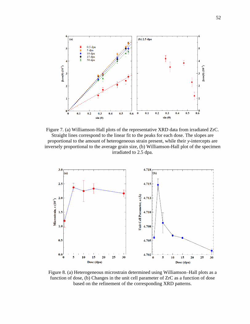
52
Figure 7. (a) Williamson-Hall plots of the representative XRD data from irradiated ZrC.
Straight lines correspond to the linear fit to the peaks for each dose. The slopes are
proportional to the amount of heterogeneous strain present, while their y-intercepts are
inversely proportional to the average grain size, (b) Williamson-Hall plot of the specimen
irradiated to 2.5 dpa.
Figure 8. (a) Heterogeneous microstrain determined using Williamson–Hall plots as a
function of dose, (b) Changes in the unit cell parameter of ZrC as a function of dose
based on the refinement of the corresponding XRD patterns.

53
Figure 9. (a) On-Zone STEM Bright Field Image of the specimen irradiated to 0.5 dpa
showing black dot defects, (b) Brigth Field Image of the specimen irradiated to 5 dpa
showing the tangle dislocation network. Some dislocation loops with bouble arc constrast
are indicated by white arrows, (c) Bright Field Image of the specimen irradiated to 30 dpa
showing the tangle dislocation network.

54
Figure 10. Raman spectra for ZrC irradiated at various doses.
REFERENCES
[1] H. F. Jackson and W. E. Lee, “Properties and characteristics of zrc,” in
Comprehensive Nuclear Materials, 2012.
[2] M. M. Opeka, I. G. Talmy, E. J. Wuchina, J. A. Zaykoski, and S. J. Causey,
“Mechanical, Thermal, and Oxidation Properties of Refractory Hafnium and
zirconium Compounds,” J. Eur. Ceram. Soc., vol. 19, no. 13–14, pp. 2405–2414,
1999.
[3] T. Ogawa and K. Ikawa, “Reaction of Pd with SiC and ZrC,” High Temp. Sci.,
1986.
[4] Y.-K. Yang and T. R. Allen, “The measurement of silver diffusivity in zirconium
carbide to study the release behavior of 110mAg in the ZrC TRISO-coated nuclear
fuel particle,” J. Nucl. Mater., vol. 470, pp. 76–83, 2016.

55
[5] Y. Katoh, G. Vasudevamurthy, T. Nozawa, and L. L. Snead, “Properties of
zirconium carbide for nuclear fuel applications,” J. Nucl. Mater., vol. 441, no. 1–3,
pp. 718–742, 2013.
[6] G. Vasudevamurthy, T. W. Knight, E. Roberts, and T. M. Adams, “Laboratory
production of zirconium carbide compacts for use in inert matrix fuels,” J. Nucl.
Mater., vol. 374, no. 1-2, pp. 241–247, 2008.
[8] X.D. Yang, Z.M. Xie, S. Miao, R. Liu, W.B. Jiang, T. Zhang, X.P. Wang, Q.F.
Fang, C.S. Liu, G.N. Luo, and X. Liu, “Tungsten-zirconium carbide-rhenium
alloys with extraordinary thermal stability,” Fusion Eng. Des., vol. 173, no. 2, pp.
200–209, 2016.
[9] K. Minato, T. Ogawa, K. Sawa, A. Ishikawa, T. Tomita, S. Iida, and H. Sekino,
“Irradiation Experiment on ZrC-Coated Fuel Particles for High-Temperature Gas-
Cooled Reactors,” Nucl. Technol., vol. 130, no. 3, pp. 272–281, 2000.
[10] K. Minato and T. Ogawa, “Advanced concepts in triso fuel,” R.J.M. Konings
(Ed.), Compr. Nucl. Mater., Elsevier, Oxford (2012), pp. 215-236.
[11] I. E. Porter, T. W. Knight, M. C. Dulude, E. Roberts, and J. Hobbs, “Design and
fabrication of an advanced TRISO fuel with ZrC coating,” Nucl. Eng. Des., vol.
259, pp. 180–186, 2013.
[12] G. Vasudemurthy, Y. Katoh, J. D. Hunn, and L. L. Snead, “Pre- and Post-
Irradiation Characterization and Properties Measurements of ZrC-coated Surrogate
TRISO Particles,” Current, 2010.
[13] L. L. Snead, Y. Katoh, and S. Kondo, “Effects of fast neutron irradiation on
zirconium carbide,” J. Nucl. Mater., vol. 399, no. 2–3, pp. 200–207, 2010.
[14] G. Vasudevamurthy, Y. Katoh, J. Aihara, K. Sawa, and L. L. Snead,
“Microstructure and mechanical properties of heat-treated and neutron irradiated
TRISO-ZrC coatings,” J. Nucl. Mater., vol. 464, pp. 245–255, 2015.
[15] D. Craciun, G. Socol, D. Simeone, S. Behdad, B. Boesl, B.S. Vasile, and V.
Craciun, “Structural and mechanical properties changes induced in nanocrystalline
ZrC thin films by Ar ion irradiation,” J. Nucl. Mater., vol. 468. pp. 78–83, 2016.
[16] S. Gomès, L. David, J.-P. Roger, G. Carlot, D. Fournier, C. Valot, and M.
Raynaud, , “Thermal conductivity degradation induced by heavy ion irradiation at
room temperature in ceramic materials,” Eur. Phys. J. Spec. Top., vol. 153, no. 1,
pp. 87–90, 2008.

56
[17] C. Jensen, M. Chirtoc, N. Horny, J. S. Antoniow, H. Pron, and H. Ban, “Thermal
conductivity profile determination in proton-irradiated ZrC by spatial and
frequency scanning thermal wave methods,” J. Appl. Phys., vol. 114, no. 13, p.
133509, 2013.
[18] D. Gosset, M. Dollé, D. Simeone, G. Baldinozzi, and L. Thomé, “Structural
behaviour of nearly stoichiometric ZrC under ion irradiation,” Nucl. Instruments
Methods Phys. Res. Sect. B Beam Interact. with Mater. Atoms, vol. 266, no. 12-13,
pp. 2801–2805, 2008.
[19] Y. Huang, B. R. Maier, and T. R. Allen, “Irradiation-induced effects of proton
irradiation on zirconium carbides with different stoichiometries,” Nucl. Eng. Des.,
vol. 277, pp. 55–63, 2014.
[20] S. Pellegrino, L. Thomé, A. Debelle, S. Miro, and P. Trocellier, “Damage
production in carbide single crystals irradiated with MeV heavy ions,” Nucl.
Instruments Methods Phys. Res. Sect. B Beam Interact. with Mater. Atoms, vol.
307, pp. 294-298, 2013.
[21] S. Agarwal, A. Bhattacharya, P. Trocellier, and S. J. Zinkle, “Helium induced
microstructure damage, nano-scale grain formation and helium retention behaviour
of ZrC,” Acta Mater., vol. 163, pp. 14–27, 2019.
[22] B. Wei, Y. Wang, H. Zhang, D. Wang, S. Peng, and Y. Zhou, “Microstructure
evolution of nonstoichiometric ZrC0.6 with ordered carbon vacancies under ion
irradiation,” Mater. Lett., vol. 228, pp. 254–257, 2018.
[23] S. Kim, I. Szlufarska, and D. Morgan, “Ab initio study of point defect structures
and energetics in ZrC,” J. Appl. Phys., vol. 107, no. 5, p. 053521, 2010.
[24] M.-J. Zheng, I. Szlufarska, and D. Morgan, “Defect kinetics and resistance to
amorphization in zirconium carbide,” J. Nucl. Mater., vol. 457, pp. 343–351,
2015.
[25] M. Jiang, J. W. Zheng, H. Y. Xiao, Z. J. Liu, and X. T. Zu, “A comparative study
of the mechanical and thermal properties of defective ZrC, TiC and SiC,” Sci.
Rep., vol. 7, no. 1, p. 9344, 2017.
[26] L. Van Brutzel and J. P. Crocombette, “Classical molecular dynamics study of
primary damage created by collision cascade in a ZrC matrix,” Nucl. Instruments
Methods Phys. Res. Sect. B Beam Interact. with Mater. Atoms, vol. 255, no. 1, pp.
141-145, 2007.
[27] G. S. Was, Fundamentals of Radiation Materials Science. New York, NY:
Springer New York, 2017.

57
[28] G. S. Was and R. S. Averback, “Radiation damage using ion beams,” Konings
(Ed.), Compr. Nucl. Mater., Elsevier, Oxford (2012), pp. 195-221.
[29] G. S. Was, “The Radiation Damage Event,” in Fundamentals of Radiation
Materials Science, New York, NY: Springer New York, 2017, pp. 3–76.
[30] J. Gan, Y. Yang, C. Dickson, and T. Allen, “Proton irradiation study of GFR
candidate ceramics,” J. Nucl. Mater., vol. 389, no. 2, pp. 317-325, 2009.
[31] C. J. Ulmer, A. T. Motta, and M. A. Kirk, “In situ ion irradiation of zirconium
carbide,” J. Nucl. Mater., vol. 466, pp. 606–614, 2015.
[32] J. Gan, M. Meyer, R. Birtcher, and T. Allen, “Microstructure Evolution in ZrC
Irradiated with Kr ions,” J. ASTM Int., vol. 3, no. 4, p. 12376, 2006.
[33] S. Pellegrino, J. P. Crocombette, A. Debelle, T. Jourdan, P. Trocellier, and L.
Thomé, “Multi-scale simulation of the experimental response of ion-irradiated
zirconium carbide: Role of interstitial clustering,” Acta Mater., vol. 102, pp. 79–
87, 2016.
[34] R. V. Sara, “The System Zirconium-Carbon,” J. Am. Ceram. Soc., vol. 48, no. 5,
pp. 243–247, 1965.
[35] C. J. Ulmer, A. T. Motta, and M. A. Kirk, “In situ ion irradiation of zirconium
carbide,” J. Nucl. Mater., vol. 466, pp. 606–614, 2015.
[36] S. J. Zinkle and J. T. Busby, “Structural materials for fission and fusion energy,”
Mater. Today, vol. 12, no. 11, pp. 12–19, 2009.
[37] S. J. Zinkle and G. S. Was, “Materials challenges in nuclear energy,” Acta Mater.,
vol. 61, no. 3, pp. 735–758, 2013.
[38] ASTM, “ASTM C373-14 Standard Test Method for Water Absorption, Bulk
Density, Apparent Porosity, and Apparent Specific Gravity of Fired Whiteware
Products,” Astm C373-88, 1999.
[39] Y. Zhang, M.L. Crespillo, H. Xue, K. Jin, C.H. Chen, C.L. Fontana, J.T. Graham,
and W.J. Weber, “New ion beam materials laboratory for materials modification
and irradiation effects research,” Nucl. Instruments Methods Phys. Res. Sect. B
Beam Interact. with Mater. Atoms, vol. 338, pp. 19-30, 2014.
[40] M. L. Crespillo, J. T. Graham, Y. Zhang, and W. J. Weber, “In-situ luminescence
monitoring of ion-induced damage evolution in SiO2 and Al2O3,” J. Lumin., vol.
172, pp. 208-218, 2016.

58
[41] M. L. Crespillo, J. T. Graham, Y. Zhang, and W. J. Weber, “Temperature
measurements during high flux ion beam irradiations,” Rev. Sci. Instrum., vol. 87,
no. 2, p. 024902, Feb. 2016.
[42] J. F. Ziegler, M. D. Ziegler, and J. P. Biersack, “SRIM - The stopping and range of
ions in matter (2010),” Nucl. Instruments Methods Phys. Res. Sect. B Beam
Interact. with Mater. Atoms, 2010.
[43] R. E. Stoller, M. B. Toloczko, G. S. Was, A. G. Certain, S. Dwaraknath, and F. A.
Garner, “On the use of SRIM for computing radiation damage exposure,” Nucl.
Instruments Methods Phys. Res. Sect. B Beam Interact. with Mater. Atoms, vol.
310, pp. 75–80, 2013.
[44] Y. Zhang et al., “Thermal stability and irradiation response of nanocrystalline
CoCrCuFeNi high-entropy alloy,” Nanotechnology, 2019.
[45] G. S. Was, Fundamentals of radiation materials science: Metals and alloys,
second edition. 2016.
[46] FullProf Team, “FullProf Suite,” FullProf Suite, 2006.
[47] W. A. Rachinger, “A Correction for the α1 and α2 Doublet in the Measurement of
Widths of X-ray Diffraction Lines,” J. Sci. Instrum., vol. 25, no. 7, pp. 254–255,
1948
[48] A. R. Stokes and A. J. C. Wilson, “The diffraction of X rays by distorted crystal
aggregates - I,” Proc. Phys. Soc., vol. 56, no. 3, pp. 174–181,1944.
[49] F. Réjasse, O. Rapaud, G. Trolliard, O. Masson, and A. Maître, “Experimental
investigation and thermodynamic evaluation of the C–Hf–O ternary system,” J.
Am. Ceram. Soc., vol. 100, no. 8, pp. 3757–3770, 2017.
[50] P. Barnier and F. Thévenot, “Synthesis and hot-pressing of single-phase ZrCxOy
and two-phase ZrCxOy-ZrO2 materials,” Int. J. High Technol. Ceram., vol. 2, no. 4,
pp. 291–307, 1986.
[51] M. Gendre, A. Maître, and G. Trolliard, “Synthesis of zirconium oxycarbide
(ZrCxOy) powders: Influence of stoichiometry on densification kinetics during
spark plasma sintering and on mechanical properties,” J. Eur. Ceram. Soc., vol. 31,
no. 13, pp. 2377–2385, 2011.
[52] B. C. Larson, “X-ray diffuse scattering near Bragg reflections for the study of
clustered defects in crystalline materials,” in Diffuse Scattering and the
Fundamental Properties of Materials, 2009.

59
[53] D. Gosset, M. Dollé, D. Simeone, G. Baldinozzi, and L. Thomé, “Structural
evolution of zirconium carbide under ion irradiation,” J. Nucl. Mater., vol. 373, no.
1–3, pp. 123–129, 2008.
[54] A. Debelle et al., “Lattice strain in irradiated materials unveils a prevalent defect
evolution mechanism,” Phys. Rev. Mater., vol. 2, no. 1, p. 013604, 2018.
[55] S. Moll et al., “Damage processes in MgO irradiated with medium-energy heavy
ions,” Acta Mater., vol. 88, pp. 2015, 2015.
[56] J. Wang et al., “Carbon Contamination During Ion Irradiation - Accurate Detection
and Characterization of its Effect on Microstructure of Ferritic/Martensitic Steels,”
Sci. Rep., vol. 7, no. 1, p. 15813, 2017.
[57] G. Gutierrez et al., “High temperature annealing of Xe implanted ZrC0.95O0.05
investigated by RBS, TEM and PAS-DBS,” Prog. Nucl. Energy, vol. 57, pp. 57–
61, 2012.
[58] C. Martin, K. H. Miller, H. Makino, D. Craciun, D. Simeone, and V. Craciun,
“Optical properties of Ar ions irradiated nanocrystalline ZrC and ZrN thin films,”
J. Nucl. Mater., vol. 488, pp. 16–21, 2017.
[59] H. Wipf, M. V. Klein, and W. S. Williams, “Vacancy-Induced and Two-Phonon
Raman Scattering in ZrCx, NbCx, HfCx, and TaCx,” Phys. status solidi, vol. 108,
no. 2, pp. 489–500, 1981.
[60] S. Pellegrino, L. Thomé, A. Debelle, S. Miro, and P. Trocellier, “Radiation effects
in carbides: TiC and ZrC versus SiC,” Nucl. Instruments Methods Phys. Res. Sect.
B Beam Interact. with Mater. Atoms, vol. 327, no. 1, pp. 103–107, 2014.
[61] W. Bao, J. Liu, X. Wang, H. Zhang, J. Xue, S. Sun, F. Xu, J. Xue, and G. Zhang,
“Structural evolution in ZrC-SiC composite irradiated by 4 MeV Au ions,” Nucl.
Instruments Methods Phys. Res. Sect. B Beam Interact. with Mater. Atoms, vol.
434, no. 1, pp. 23–28, 2018.
[62] Y. Zhang, J. Wang, B. Liu, J. Wang, and H. Zhang, “Understanding the Behavior
of Native Point Defects in ZrC by First-Principles Calculations,” J. Am. Ceram.
Soc., vol. 97, no. 12, pp. 4024–4030, 2014.

60
II. EARLY STAGE OXIDATION OF ZrCx UNDER ION-IRRADIATION
AT ELEVATED TEMPERATURES
Raul Floreza, Miguel L. Crespillob, Xiaoqing Hec,d, Tommi A. Whitec,e,
Gregory Hilmasf, William G. Fahrenholtzf, Joseph Grahama,f*
a. Nuclear Engineering Program, Missouri University of Science and Technology,
65409 Rolla, MO, United States
b. Department of Material Science and Engineering, University of Tennessee, 37996
Knoxville, TN, United States
c. Electron Microscopy Core, University of Missouri, Columbia,
Missouri 65211, United States
d. Department of Mechanical and Aerospace Engineering, University of Missouri,
Columbia, MO 65211, USA
e. Department of Biochemistry, University of Missouri, Columbia,
Missouri 65211, United States
f. Department of Materials Science and Engineering, Missouri University of Science
and Technology, 65409 Rolla, MO, United States
ABSTRACT
The effects of irradiation on the morphology and microstructure of the oxide
formed on the surface of ZrCx during irradiation with 10 MeV Au3+ ions at 800o C were
investigated. Nanosized oxide islands were observed on both unirradiated and irradiated
sample areas, indicating that the early stage oxidation of ZrCx proceeded via nucleation
and growth. The reduction in size and surface coverage of oxide nodules at high doses,
indicated that oxide dissolution was the predominant mechanism under irradiation

61
conditions. Nanometric cavities were observed in oxide islands for samples irradiated
above 2.5 dpa. The underlying mechanisms driving these changes were discussed.
Keywords: ZrC, ZrO2, Oxidation, Ion irradiation, Electron Microscopy, GIXRD.
* Corresponding author:
Email: [email protected]
1. INTRODUCTION
Zirconium carbide (ZrCx) is an ultra-high-temperature ceramic (UTHC) material
with outstanding mechanical strength, high thermal and electrical conductivity, and low
neutron absorption cross section [1], [2]. This unusual combination of properties makes
ZrCx an attractive material for a variety of applications, including nuclear reactors [2],
aerospace and propulsion devices [3], high power density microelectronics [4], and solar
power concentrators [5]. Particularly in the nuclear field, ZrCx ceramics have gained
significant interest as promising contenders for future advanced Generation-IV nuclear
reactors and fusion systems. In these type of nuclear reactors ZrCx could potentially be
used as an inert fuel matrix [6], a plasma facing component (PFC) [7], an oxygen getter
for microencapsulated fuels [8], an alternative cladding for advanced non-light water
reactors [9], and a fission product barrier in Tri-structural Isotropic (TRISO) fuel
particles [10]. As a potential in-core material for the next generation of nuclear systems,
ZrC would be subject to extreme operation conditions combining high radiation fluxes,
elevated temperatures, mechanical stresses, and aggressive chemical environments.

62
The primary coolant system considered for Gen-IV high-temperature and very-
high-temperature gas-cooled reactors (HTGRs and VHTRs) is helium gas, which is
known for its chemical inertness [11]. Although the primary coolant system of HTRs and
VHTRs is fitted with purification systems, impurities i including H2, CO, H2O, CO2,
CH4, O2, and N2 are inevitable in the coolant [12], [13], [14]. These impurities might arise
from different sources including leaks into the cooling system, gas desorption from the
nuclear fuel and other structural components, and nuclear fission reactions. Under
prototypic operation conditions for gas-cooled reactor, the concentrations of impurities in
the coolant system are in the part per million range [15]. Despite that, these impurities
can induce corrosion reactions at high temperatures (>500 oC), which can strongly affect
the properties of the in-core reactor materials [16]. Previous studies have demonstrated
that oxygen partial pressures (Po2) as low as 10-5 Pa can lead to the oxidation of ZrCx
ceramics at temperatures above 500o C [17]. As a result, the oxidizing impurities in the
helium coolant bear the risk of oxidation of the ZrC-based components during the
operation of gas-cooled reactors. In-service oxidation of ZrCx may induce significant
changes in thermophysical and mechanical properties of ZrCx [18]. Moreover, the in-
service oxidation of ZrCx can enhance the release of gaseous fission products such as
xenon (Xe) and helium (He) [19], [20]. Likewise, nanometric ZrO2 precipitates exhibit
catalytic properties towards water splitting and hydrocarbon cracking [21], [22], which
could enhance the uptake of other impurities into ZrCx. Since the properties of ZrCx can
be seriously compromised by in-service oxidation, it is of important to elucidate the
morphological and structural changes induced by oxidation of ZrCx.

63
The oxidation behavior of ZrCx ceramics at various experimental conditions has
been extensively studied by a number of investigators [23], [24], [25] [26], [27], [28],
[29], [30], [31]. When ZrCx is exposed to an oxidizing atmosphere at elevated
temperatures (> 500 oC), ZrO2 and C are formed according to the following reactions:
𝑍𝑟𝐶 +1
2(1 − 𝑥)𝑂2 → 𝑍𝑟𝐶𝑥𝑂1−𝑥 + (1 − 𝑥)𝐶 (1)
𝑍𝑟𝐶𝑥𝑂1−𝑥 +1
2(1 +
𝑥
2) 𝑂2 → 𝑍𝑟𝑂2 + (𝑥)𝐶𝑂 (2)
Previous studies have recognized four different temperature regimes of oxidation
for ZrCx [18]. The low temperature regime occurs between 400 and 600 oC. In this
regime, an oxide scale composed of amorphous ZrO2 and free carbon forms on the
surface of the unoxidized ZrCx matrix. Before the formation of ZrO2, ZrC goes through
an oxycarbide transformation phase as described by reactions (1) and (2). The formation
of the oxycarbide phase is quite rapid and the rate is controlled by the phase boundary
reaction. The second oxidation regime occurs between 600 oC and 800 oC. In this
temperature range, cubic zirconia (c-ZrO2) starts to nucleate from the amorphous zirconia
and the crystals begin to growth. Also, low levels of CO start to form by oxidation of free
carbon. The kinetics in this regime are controlled by diffusion of oxygen through the
scale with no significant stress on the c-ZrO2 grains. The third regime occurs between 800
oC and 1000 oC. At these temperatures, the c-ZrO2 crystals grow larger than 10 nm and
monoclinic and tetragonal ZrO2 polymorphs begin to appear. Nearly all the free carbon
inclusions are oxidized during this regime; therefore, a porous ZrO2 layer covers the
surface. The kinetics in the third regime are controlled by oxygen grain boundary
diffusion. Finally, at temperatures above 1200 oC, the zirconia layer (mostly m-ZrO2)

64
begins to sinter closing the pores created by CO2 effusion. Uncertainty exists on the
actual temperature and oxygen partial pressure values at which phase and rate controlling
mechanism transitions occur.
Although the high temperature oxidation behavior of ZrCx has been extensively
investigated during the last three decades, experimental data are lacking for the oxidation
of ZrC under normal operating conditions in high temperature gas-cooled reactors. Until
now, most of the published work has dealt with the oxidation of ZrCx following a loss of
coolant accident (LOCA) [26], [27]. Under LOCA conditions, an oxide scale is rapidly
formed on the surface of ZrCx due to the undesirable high-temperature exposure to an air-
steam atmosphere. In contrast, in-service oxidation of ZrCx does not occur in oxygen-rich
atmospheres; therefore, one can expect that the oxidation rate, surface composition and
oxide structures would be different from those observed during LOCA scenarios. Many
questions remain about the formation mechanism and the structure of the oxide formed
on ZrCx during in-service operation in high temperature gas-cooled reactors. Particularly,
the physical and chemical transformations that occur during the early stage of oxidation
of ZrCx are not understood. A recent study by Pipon et al [32] indicated that the early
stages of ZrCx oxidation are controlled by the nucleation and growth of discrete oxide
nuclei, which are particularly prominent at low oxygen partial pressure and high
temperatures. To the best of our knowledge, a detailed microstructural characterization of
the initial oxides formed on the ZrCx surface during the early stages of the oxidation is
not available. Therefore, elucidating the oxidation reaction and the microstructural
evolution of the oxide scale at the early stages is essential to mitigate ZrCx oxidation in
nuclear reactor systems. Additionally, the effects of radiation on the oxidation behavior
65
of ZrCx remain largely unknown. Most studies listed above have performed only out-pile
ZrCx oxidation experiments. The main limitation of out-pile oxidation experiments is the
absence of irradiation effects, which are ubiquitous in nuclear reactors. Radiation can
significantly modify the oxidation behavior of ZrCx compared to out-pile oxidation
experiments by changing the properties of the ceramic matrix, the oxide formed on the
surface, and the oxidizing environment [33],[34]. As far as we know, no previous studies
have focused on in-pile oxidation of ZrC.Consequently, more experiments must be
conducted to understand the effects of radiation on the oxidation behavior of ZrCx. To
this end, specimens must be irradiated under conditions of direct relevance to high
temperature gas-cooled reactors, while simultaneously exposed to an oxidizing
atmosphere with impurity levels similar to those encountered in the helium coolant of
HTRs and VHTRs.
The purpose of this paper was to investigate the microstructure of the oxides
formed on the surface of ZrCx during ion irradiation with Au3+ ions at 8000C. The oxides
were characterized for both the irradiated and unirradiated specimens to understand the
effect of irradiation on the morphology and microstructure of the oxide scale. The results
provide new insights into the early stage oxidation of ZrCx under in-pile conditions
relevant to high temperature gas-cooled nuclear reactors.

66
2. EXPERIMENTAL PROCEDURE
2.1. SAMPLE PREPARATION
A pellet of ZrC was prepared by hot-pressing commercial ZrC powder (Alfa
Aesar, Reactor Grade, USA). The as-received powder was hot pressed in a 25.4 mm
cylindrical graphite die lined with BN-coated (SP-180 Cerac, Milwaukie, WI) graphite
foil (2010-A; Mineral Seal Corp, Tucson, Arizona). Before hot pressing, the powder was
loaded into the die and cold compacted in a uniaxial press at ~2MPa. The powder was
then heated under vacuum to 1600 0C with an average heating rate of 20 0C/min. At that
time, the furnace was backfilled with helium and a uniaxial pressure of 32 MPa was
applied to the powder compact. The furnace was then heated at 50 0C/min to 2200 0C.
After 90 min, the furnace was cooled at ~50 0C/min. The load was removed when the die
temperature dropped below 1600 0C.
Following densification, specimens for microscopy and ion irradiations were cut
parallel to the hot pressing of the billet direction with a slow-speed diamond saw and then
ground and polished to mirror-finish. The metallographic preparation was carried out by
grinding the specimens with 100, 320, 600 and 1200 grit SiC pads with water as the
lubricant. Felt pads and water-based diamond slurry suspensions were used for abrasive
sizes from 3 µm to 0.25 µm. After polishing, the specimens were ultrasonically cleaned
with ethanol for 15 min at room temperature.
2.2. ION IRRADIATIONS
A rectangular ZrC foil (13 x 8 mm) was irradiated in the Ion Beam Materials
Laboratory (IBML UT-ORNL) at the University of Tennessee, Knoxville [35] with 10

67
MeV Au3+ ions at 800 C using a 3.0 MV tandem accelerator. Five different regions of the
ZrC foil (3x3 mm each) were irradiated to doses of 0.5, 2.5, 5, 10, and 15 dpa. The total
sample area comprised the five non-overlapping irradiated regions and one unirradiated
control spot. Adjustable beam slits were used to define the irradiation areas. The ion
beam was defocused and rastered in the horizontal and vertical directions with the aim of
producing a region that was homogeneously irradiated. Beam homogeneity was verified
by ion-induced luminescence from quartz targets and was found to be within 10%
throughout the irradiated area [36]. The flux was set at 1.0 ×1012 cm-2 s-1 for all fluences.
Low beam current densities in the range of 5 nA mm-2 were used to reduce any undesired
effect and charge accumulation on the samples [37]. The vacuum chamber pressure was
observed to be below 5 ×10⁻⁸ torr prior heating. Sample heating caused the pressure in
the irradiation chamber to rise initially, but it decreased into the range of 3-5 x10⁻⁷ torr
during irradiation. The maximum outgassing of the specimen was observed around 170o
C with vacuum pressure levels of 7.8 x 10⁻⁶ torr (Figure 1a). The Stopping and Range of
Ions in Matter binary collision approximation (BCA) code 2013 version (SRIM-2013)
[38] was used to estimate the displacement damage depth profile. Cascades were
performed in quick-cascade mode (simple Kinchin and Pease model) assuming a density
of 6.71 g/cm3 and threshold displacement energies of 37 eV for Zr and 16 eV for C [39]
and C respectively. To compare ion and neutron irradiation results, the use of the quick
Kinchin–Pease option in SRIM to compute radiation damage exposure has been
recommended within the nuclear community [40]. The damage profile estimated from
SRIM is determined by the sum of the predicted vacancy concentrations (using 'Knock-
Ons' from Au ions and 'Vacancies' from target elements of Zr and C, together with the

68
replacement collisions [41]. Assuming a bulk ZrC sample, the predicted damage profile
in displacements per atom (dpa) and the implanted Au ion profile are shown in Figure 1a.
The peak dose under 10 MeV Au irradiation was located around 1000 nm below the
surface. The conversion factor from ion fluence (1014 cm−2) to local dose in the ZrC foil
under quick simulation was 0.8343 dpa. The steady state temperature of the sample
surface was measured via a K-type (chromel-alumel) thermocouple (TC). The TC was
attached to the sample surface by molybdenum spring-loaded clips. Samples mounted on
the high temperature stage were conductively heated from the platen. The rear of the
platen was radiatively heated using a resistively heated tungsten filament. (ERH series
heater and EPS-500 power supply, Thermionics Northwest, Inc.). High performance
silver paste was used to improve the thermal contact between the bottom surface of the
sample and the platen. More details on the experimental apparatus are provided
elsewhere [35],[37]. Irradiations were performed with Au ions because of their relatively
inert nature and large nuclear stopping cross section, which allows for a high damage rate
per incident ion and minimal artifacts induced by the injected ions. It is worth noting that
10 MeV energy beam was chosen to obtain a relatively flat profile to a depth of 1 µm
without appreciable effects of implanted Au ions (Figure 1b). Moreover, intermediate
energy heavy ion irradiations produce a displacement cascade density and morphology
more similar to fission neutrons than light ions irradiation, which produces a more sparse
sub-cascade morphology [42]. The temperature and range of doses were selected with the
goal of studying radiation damage mechanisms in regimes relevant to the conditions in
Gen-IV high temperature gas-cooled reactors and advanced fission and fusion reactor
systems [43].

69
2.3. MATERIAL CHARACTERIZATION
This section presents a description of the different experimental techniques that
were used in the present work to examine the samples.
2.3.1. Density and Chemical Analysis. The bulk density of the hot-pressed billet
was measured by the Archimedes’ method using distilled water as the immersing
medium, according to ASTM C73-88 [44]. The relative density was calculated by
dividing the Archimedes’ density by the estimated theoretical density of ZrC (𝜌=6.71
g/cm3). The chemical analysis for carbon, oxygen and nitrogen contents of the billet was
conducted by direct combustion method using the infrared absorption detection
technique. Carbon (CS600; Leco, St. Joseph, MI), oxygen and nitrogen (TC500; Leco, St.
Joseph, MI) contents were measured by crushing dense specimens to ~200 mesh. Three
measurements were conducted for each element to establish repeatability.
2.3.2. Grazing Incidence X-Ray Diffraction. Grazing incidence X-ray
diffraction (GIXRD) measurements were performed to evaluate structural modifications
in the near surface region following high temperature ion irradiations. GIXRD profiles
were collected on a PANanlytical X’Pert Pro Multipurpose Diffractometer (MPD) fitted
with a Cu X-ray tube and a X’Celerator detector. The diffraction patterns were acquired
in grazing incidence geometry over the 2θ range 25 to 90 degrees with a step size of 0.030
and counting time of 0.5 s at each step. X-ray tube operation conditions were 40 kV and
40 mA.
2.3.3. Electron Microscopy. The surface morphology and composition were
examined for both pristine and irradiated by focused ion beam (FIB)- scanning electron
microscopy (FIB SEM, SciosTM DualBeamTM, FEI, Hillsboro, Oregon) coupled with

70
energy dispersive spectroscopy (EDS; Oxford Instrument Avignon UK). TEM specimens
were also prepared using focused-ion-beam (FIB) lift out technique with a SciosTM
DualBeamTM equipped with Ga focused ion beam. Before milling, a 2 µm thick Pt layer
was deposited the top surface of the specimen to protect it from ion beam induced
damage and unwanted surface milling during FIB preparation. Trenching was performed
at an ion beam voltage of 30 kV with a beam current of a few nanoamps. After lift -out,
thinning of the lamella was first conducted with a beam current of hundreds of
picoamps at 30 kV at 5 on both sides of the lamella using cleaning cross section
mode until the lamella was ~1 m thick. Voltages and currents were gradually
reduced, and the milling angles decreased as the lamella got thinner. To complete
preparation, a gentle polishing with Ga+ ions (5 keV and 48 pA) was used to remove
damage caused by higher energy Ga bombardment. Microstructure characterization was
performed using a 300 kV Technai F30 Supertwin transmission electron microscope
(TEM). High resolution transmission electron microscopy (HRTEM) was used to reveal
microstructural details of the oxide scale. Bright field (BF) imaging techniques were used
to elucidate the radiation induced microstructural defects. Energy dispersive X-ray
spectroscopy (EDX) and electron energy loss spectroscopy (EELS) were used for
chemical composition studies.

71
3. RESULTS
3.1. AS-SINTERED SAMPLE
The as-sintered ZrC pellet had a relative density of 93%. The carbon, oxygen and
nitrogen content were 11.62, 0.144, and 0.0251 wt % respectively. Before annealing, the
surface of the control specimen consisted of a homogeneous microstructure of ZrC grains
with some residual porosity characteristic of non-fully densified billets. The average
grain size was 5.1 ±1.8 µm.
3.2. ANNEALED UNIRRADIATED SAMPLE
GIXRD patterns obtained at ω=0.5o for the control specimen before and after
thermal annealing in the ion irradiation vacuum chamber are presented in Figure 2a. The
analyzed 2θ range included six peaks of the typical rock salt structure of ZrC (𝐹𝑚3̅𝑚)
and the expected diffraction reflections for ZrO2 polymorphs produced by the oxidation.
Before annealing, XRD analysis revealed that nominally pure ZrC was the only
crystalline phase present in the as-sintered billet. After annealing, new peaks
corresponding to ZrO2 polymorphs were observed in the XRD pattern. This result clearly
indicates that the near surface area of the specimen was oxidized after exposure to the
residual vacuum (<10-7 torr) of the ion accelerator chamber at 800 0C. The assignment of
type of ZrO2 polymorph could not be done unambiguously due to the closeness of the
XRD peak positions for monoclinic (m), tetragonal (t) and cubic (c) ZrO2 in the evaluated
2θ range. The peak at 2θ=300 is due to the presence of either t- or c-ZrO2 polymorph(s)
and/or oxygen-deficient m-ZrO2-x.
72
Figure 2b shows GIXRD patterns, obtained at ω values of 0.5, 1, 1.5, 3 and 5o,
from the unirradiated ZrC sample after annealing for 5h at 800o C. The scans were
recorded at several incident angles to probe microstructural changes at different
penetration depths. The intensity of the ZrO2 peaks decreased as the incident angle ω
increased, suggesting that the oxide phase was concentrated in the near surface region.
Further analysis of the ZrC reflections revealed changes in the broadening and position of
the peaks as a function of the incident angle ω. ZrC peaks shifted to higher angles when
the X-ray incident angle decreased. Peak shifting to higher 2θ angles is indicative of a
contraction of the unit cell parameter, which could be produced by compositional
changes across the probed area. In this case, the peak shifting could be attributed to the
incorporation of adventitious oxygen into the ZrC lattice to form zirconium oxycarbide
(ZrCxOy) [45]. The change in lattice parameter for ZrC is consistent with increasing
oxygen content closer to the surface of the specimen.
FESEM plain view micrographs of the unirradiated specimen after annealing
(Figure 3a) showed several morphological changes with respect to the original polished
surface. First, the grain boundaries of the specimen were revealed due to the preferential
thermal etching during annealing. Second, the surface was covered by discrete
nanoprecipitates distributed homogeneously across the grains of the underlying ZrCx. The
nanoprecipitates ranged in sizes between 20 and 100 nm. EDX elemental maps were
acquired in the box area marked in Figure 3a to analyze the composition after annealing.
The area selected for analysis included grain boundary regions where fewer of
precipitates was observed. The elemental maps indicated that Zr, C and O were the major
constituents on the surface area of the annealed sample (Figure 3b). The concentration of
73
zirconium and carbon was uniform across the analyzed area; whereas the concentration of
oxygen s was lower at the grain boundaries. This suggests that the nanoprecipitates
observed in the SEM images contain oxygen, which is consistent with the detection of
zirconium oxide by GIXRD. A standardless semi-quantitative EDX analysis of the
mapping area (Figure 3c) gave the composition of 51 at% C, 45 at% Zr, and 4 at% O.
Although oxygen enrichment is evident in the near surface area of oxidized specimen, the
EDX signal from the nanoprecipitates on the surface can be easily overcome by
contributions from the underlying ZrCx matrix due to the large interaction volume of 20
keV electrons. Moreover, an accurate quantification of oxygen and carbon is not possible
by EDX due to the low sensitivity of the technique for the light elements.
The density and sizes of the precipitates appeared to vary from grain to grain,
suggesting that the nucleation and growth of the oxide islands was influenced by the
crystallographic orientation of the underlying ZrCx. The oxide nanoprecipitates seem to
grow preferentially within the grain areas, while precipitate-denuded zones were
observed near the grain boundaries. In general, the oxide particles had a lenticular shape
with a faceted free surface and a rounded ZrC/ZrO2 interface (Figure S1a). The latter
suggested high wettability of the oxide phase on the underlaying ZrCx substrate.
Additionally, some of the oxide nanoislands began to coalesce with neighboring
precipitates leading to the formation of larger oxide islands (Figure S1b). The
coalescence indicated that coarsening of the oxide nanoprecipitates began at the early
stages of the oxidation process, even when the grain boundaries were free of of oxide
nodules.

74
Cross-sectional HRTEM images of the unirradiated specimen after annealing is
shown in Figure 4a. A multilayer structure was observed in the near region. The surface
of the ZrC specimen was covered by a nanocrystalline layer ~ 4 nm thick and, an
amorphous layer. The chemical composition of the amorphous and nanocrystalline layers
was probed by EELS The STEM-high angle annular dark filed (HAADF) image of the
analyzed region (Figure 4b) showed a dark layer (Point A) and a uniform gray layer
(Point B), which correspond to the amorphous and nanocrystalline layers observed in
Figure 4a . The EELS spectrum obtained at point A (Figure 4c) confirmed that the
amorphous layer was carbon rich. This carbon-rich layer could have been deposited on
the surface of the specimen during preparation for TEM analysis. On the other hand, the
EELS spectrum acquired at point B (Figure 4d) indicated that the nanocrystalline layer
was most likely ZrO2. Interestingly, the nanocrystalline ZrO2 layer showed conformal
coverage on the surface of ZrC (Figure S3). Two elemental EELS line profiles
reconstructed for O and Zr are shown in Figure 4e and 4f. Notably, the onsets of the O
and Zr agreed with each other and can be clearly linked with the interface between the
dark and the grey layers in the HAADF image. Furthermore, as shown in Figure 4f,
underneath the nanocrystalline ZrO2 layer (layer I) was a layer of crystalline ZrC (layer
II) that was 25 nm thick and oxygen rich compared to the bulk ZrC. The oxygen
content decreased continuously from the top surface towards the unoxidized ZrC matrix.
Such oxygen gradient suggested that the oxidation was promoted by the uptake of
residual oxygen from the ion accelerator chamber during the annealing experiment.
Figure 5a shows a HRTEM image of an area of the annealed unirradiated sample
where the continuity of the nanocrystalline oxide layer was interrupted by the formation

75
of larger nanosized islands. The chemical composition of the islands was consistent with
ZrO2 as confirmed by EELS analysis (Figure 5d). The oxide islands had a characteristic
elongated shape with the elongation direction roughly along the {110} direction of the
ZrC substrate. Additionally, the islands were partially embedded into the ZrC matrix
forming a sigmoidal interface between the oxide and the substrate. This interface
appeared to be regular, well adhered and coherent. No precipitates of amorphous and/or
crystalline carbon were observed at the interfacial region of the analyzed nanoislands.
The intruded regions of the oxide precipitates had contact angles with the ZrC substrate
ranging from 55 to 65º; whereas the protruded regions of the oxide nodule had wetting
angles between 30 and 55º.
A Fast Fourier Transform (FFT) pattern was acquired at the red squared region
indicated in Figure 5a. The obtained FFT pattern is shown in Figure 5b and can be well
indexed along the [-121] zone axis based on a tetragonal ZrO2 structure (Inorganic
Crystal Structure Database-66784). To confirm the validity of the indexing, a simulated
electron diffraction pattern of the ZrO2 tetragonal structure was obtained using the
CrystalmakerTM software (Figure 5c). Good agreement is obtained between the
experimental and simulated FFT patterns. Fig. 5e shows the FFT pattern acquired from
an area in Figure 5a that included both the nanoisland precipitate and the ZrC matrix. It is
noted that the precipitate was epitaxially grown on the ZrC surface with the epitaxial
relationship being ( 101− −
)T// (002)M and [121−
]T// [110]M.

76
3.3. IRRADIATED SAMPLES
The XRD patterns for the irradiated samples (Fig. S2) revealed the presence of
defective but crystalline ZrC phase at all doses. Additionally, weak peaks were observed
around 2θ=300 in some of the irradiated specimens; although the intensity of this peak
was too weak to be clearly deconvoluted from the background. The low intensity of the
ZrO2 peak in the irradiated samples could be because the volume fraction of ZrO2 was
too small to produce XRD peaks that were discernible from the background signal.
Another possibility is that the oxide phase amorphized during irradiation. The surfaces of
irradiated samples were analyzed as discussed below to characterize changes that occur
during irradiation.
Figure 6 presents high resolution SEM micrographs of the surface of the control
specimen and samples irradiated to 2.5, 10 and 15 dpa. Each image is shown together
with the histogram of the maximum diameter of ZrO2 nanoislands. Given the polyhedral
shape of the precipitates, the maximum diameter was considered to provide information
about both nanoisland size and shape. The morphological evolution of the oxide
nanoislands coverages as a function of irradiation dose is shown in Figure 6. After
annealing, the surface of control sample was decorated with large oxide islands with
complex shapes, reflecting some coalescence of the oxide precipitates as the thermal
annealing proceeded as discussed above. Irradiation shifted the distribution to finer sizes,
increased the circularity of the islands, and reduced the grain area that was covered
(Table 1). The shrinking and reshaping of the precipitates at higher doses suggested that
radiation influenced the stability of the nanoislands.

77
High resolution TEM images of the oxide islands formed at different doses were
taken from the [110] zone axis of the ZrC matrix (Figure 7.) Morphological and
interfacial changes were observed in the oxide nodules as the irradiation dose is
increased. At low doses (0.5 dpa), the oxide particles showed a double cap morphology
with approximately half of the oxide island semi-embedded into the ZrC matrix and the
other half protruded above the surface. Further analysis of the interfacial area revealed no
coherent relationship between the oxide nodule and the ZrC matrix. As dose increased,
the oxide islands tended to become more faceted and the interfacial region became more
diffuse (Figure 7c, d and e). Interestingly, the phases of ZrO2 tended to be monoclinic
above 2.5 dpa after analyzing all the HRTEM images acquired, suggesting that irradiation
affected the phase of the ZrO2 that formed. Moiré fringes were observed at the
oxide/matrix interface in some of the HRTEM images of irradiated samples. Faceted
regions were also observed within the ZrO2 islands irradiated above 2.5 dpa. Some of
these regions had a characteristic octahedral shape with sizes ranging between 3 and 10
nm. Overfocus/underfocus TEM analysis was conducted on oxide nodules with faceted
regions to elucidate the character of these microstructural features. Figure 8 shows the
Fresnel contrast change under different focusing conditions in an oxide nodule irradiated
to 5 dpa. The faceted regions appeared as white features in under-focused conditions and
black features in over-focused conditions. This contrast change is characteristic of
cavities, suggesting that the faceted regions could be voids or bubbles that formed under
irradiation conditions [46].

78
4. DISCUSSION
4.1. EARLY STAGE OXIDATION OF ZrC
As shown in Figure 1, the gas pressure in the irradiation chamber increased
substantially during heating of the target at temperatures between 150-170 0C. This
observation indicates that gases desorbed from the specimen during during this stage of
the heating processes. The chemical composition of the outgassing products could not be
identified in this study because the ion accelerator chamber at the IBML is not currently
fitted with a residual gas analyzer. However, the pressure increase was probably
produced by the release of carbon impurities and/or water vapor previously trapped or
adsorbed in the solid during metallurgical preparation steps and handling of the sample.
We speculate that these impurities could have played a role in the initial oxidation of
ZrC. Similar outgassing processes could occur during the start-up and refueling stages of
high temperature gas-cooled reactors [47]. Therefore, the experimental conditions inside
the irradiation chamber observed in this experiment are akin to those expected in the
nuclear reactor core.
The discrete oxide nanostructure observed on the surface of the unirradiated
sample after annealing indicates that the oxidation process was on going. At the early
stages, the oxidation of ZrC proceeds through nucleation and growth of oxide precipitates
as depicted in Figure 3 and 5. These results are similar to those obtained by Pipon et al.
[19] after annealing ZrC0.95O0.05 at 14000C in dynamic secondary vacuum (10-5 Pa) for 3
hours. The early oxidation of other UTHCs and metals has also been found to proceed via
nucleation and growth of oxide nanoislands under high temperature and vacuum

79
conditions [48], [49], [50]. Alternatively, the formation of oxide islands can be due to
dewetting of the thin oxide passivation layer formed at the early stages of the oxidation
process. Due to excess surface free energy, thin oxide films are unstable and when they
are heated, they will dewet or agglomerate to form islands [51]. Dewetting and
nanopattern formation can be further induced by ion-irradiation [52]. Future work In-situ
oxidation experiments in an environmental TEM instrument to confirm oxide dewetting
at the arly stages of ZrCx oxidation.
The double-layer structure of the oxide scale observed in the unirradiated
specimen after annealing (Figure 4) is consistent with the morphological changes
expected according to the oxidation mechanism proposed by Katoh [2]. In the present
work, an oxygen gradient was detected by EELS analysis in the near surface area of the
annealed specimen (Figure 4b). The decrease in oxygen content with increasing distance
from the surface suggests that oxygen dissolution occurred at the interface, forming an
oxycarbide compound in the near surface area of the sample. Because of the sub-
stoichiometric nature of the as-sintered billet used in this study (detected by Raman
measurements, not shown here), it is conceivable that oxygen diffused towards carbon
vacancies in ZrCx (Equation. 3)
𝑉𝐶 +1
2𝑂2 → 𝑂𝐶 (3)
Experimental work by Shimada and Ishil [23] showed that the ZrCx containing
dissolved oxygen becomes thermodynamically unstable after the oxygen concentration
exceeds the solubility limit. As a result, the oxycarbide solution decomposes into a layer
of amorphous zirconia and free carbon. Subsequently, ZrO2 crystallites nucleate and
growth from this amorphous layer and forms a continuous film at longer oxidation times.

80
Similar results were obtained in this study for the oxidation of the unirradiated sample.
Figure 4a shows that an outer thin layer of nanocrystalline ZrO2 (around 4 nm thickness)
was formed on the top surface of the unirradiated sample after high vacuum thermal
annealing.
Previous studies suggest that free carbon is retained in the amorphous layer below
8000 C and evolves as CO orCO2 at higher temperatures [23]. However, in all previous
studies ZrC was oxidized for longer times and with an abundance of oxygen. Those
conditions favor the formation of an oxide film that results in a uniform oxygen activity
macroscopically across the sample. The gradient in oxygen activity perpendicular to the
surface promotes the retention of carbon under the oxide scale as observed extensively in
previous work. However, in our case the oxidation has just been initiated and it is
unlikely that a global change in the oxygen activity occurs at such early stages of the
oxidation process.
Cross sectional TEM images of the oxide scale also revealed that the ZrO2
crystallites were partially embedded into the underlying ZrC matrix rather than lying on
the top surface (Figure 5a). This embedding behavior has been previously observed in the
early stage oxidation of other pure metals and alloys [53], [54], [55]. Embedding of the
oxide embryos suggests that the oxide islands are formed by a 3D nucleation
mechanism, which occurs when the surface mobility of oxygen is the dominant transport
mechanism for the initial oxide formation [56]. Under such conditions, atomic oxygen
diffuses over the surface and react with the underlying substrate atoms to form semi-
buried oxide embryos. The formation of an internal oxide/substrate interface could also

81
provide a fast pathway for oxygen diffusion into the matrix, which might contribute to
further embedding of the oxide island during the growth stage.
The formation of sub-stoichiometric zirconia seems possible considering the low
oxygen partial pressure and high temperature conditions used in this study. Ma et al. [57]
have previously reported the formation of sub-oxides ZrO2-x during the oxidation of Zr
under high vacuum conditions (PO2 <10-8 torr). Similarly, the occurrence of oxygen
deficient m-ZrO2 has been observed at the interfacial region between the carbide and
oxide during oxidation of ZrCx [26]. On the other hand, the presence of t/c-ZrO2
polymorph(s) cannot be dismissed either. Prior studies on ZrC oxidation have reported
the formation of metastable t/c-ZrO2 phases during the oxidation of ZrC [58][26]. The
stabilization of t/c-ZrO2 at temperatures below the conventional polymorphic stability
range of these phases could be caused by several factors including crystallite size, strain,
and structural defects. According to Garvie’s theory [59], the formation of t- ZrO2 is
favored below a critical crystallite size of 10 nm because of the lower surface free energy
of t- ZrO2 compared to m- ZrO2. Likewise, stabilization of t- ZrO2 could be induced by
strain effects [60]. Compressive stresses generated by Pilling-Bedworth ratio (PBR)
effect and heteroepitaxial growth of the oxide can increase the critical size of stabilized t-
ZrO2 up to 200 nm [61], [62]. The presence of structural defects has been also proposed
as a mechanism for t/c ZrO2 polymorphs stabilization. According to Shukla and Seal
[61], the stabilization of tetragonal and cubic ZrO2 can be attributed to the presence of
oxygen ion vacancies generated either at higher temperature, or in vacuum, or by doping
trivalent impurities. In our case, the oxide was formed under high temperature and
vacuum conditions, which are conducive for the formation of oxygen vacancies.

82
4.2. OXIDATION UNDER IRRADIATION CONDITIONS
For the irradiated samples, some of the large ZrO2 nanoislands exhibits a series of
structural defects (Figure 6); however, they remained crystalline even after irradiation at
the highest dose evaluated in this work (15 dpa). This result agrees with previous
experimental data [63], [64]and first principle simulations [65], [66], which indicate the
high amorphization resistance for ZrO2 polymorphs under irradiation conditions. The
high radiation tolerance of ZrO2 has been attributed to the large amount of native oxygen
vacancies that enhances the dynamic recovery of the radiation induced defects [67].
Under irradiation conditions, the oxide islands are subject to several radiation-
induced processes that determine their morphological and microstructural evolution
(Figure 9b). The protruded regions of the ZrO2 nodules are sputtered by the incident ion
beam. As shown in Figure 6, the protruded regions of the nanoislands tended to become
more faceted at higher doses. The reshaping of islands was more noticeable on the sides
parallel to ion beam direction, suggesting that preferential ion sputtering occurred along
this direction. Ballistic collisions with the Au3+ ions could also produce ion beam mixing
at the ZrO2/ZrC interface. As indicated by the yellow boxes in Figure 6, irradiation
tended to make the oxide/matrix interface more diffuse. Furthermore, Moiré fringes were
observed in some of the irradiated precipitates. These observations were indicative that
intermixing between the oxide particles and ZrC phases occurred during the ion
irradiation of the specimens. Surface sputtering and ballistic mixing could enhance the
dissolution of the oxide precipitates under radiation exposure. The atoms ejected out of
the oxide particles might undergo three different processes: (i) dissolve into the ZrC
matrix, (ii) diffuse back into the parent particle or being absorbed by other particles, and

83
(iii) re-nucleate to form new particles with other solute atoms in the ZrC matrix. The last
two process depend much on the diffusion of solute atoms, particularly oxygen atoms.
Interestingly, no “halo” effect (i.e. formation of smaller oxide nanoparticles around the
periphery the islands) was observed in the oxide/matrix interface for the irradiated
samples. This suggests that the local composition of oxygen ejected from the islands
does not exceed the solubility limit in the irradiated ZrC matrix. Thus, the nucleation and
growth of smaller oxide cluster around the island is not possible. The absence of
‘haloing’ may be also related to other radiation-induced effects. Firstly, the
supersaturation of defects created under irradiation conditions can increase the oxygen
solubility in the matrix [68]. Since the solubility increases during the irradiation, atoms
ejected by ballistic mixing may be in solution during irradiation. Secondly, the defect
supersaturation can produce enhancement of diffusion processes [69]. Radiation
enhanced diffusion of sufficiently mobile species might occur either through vacancies or
interstitials and can significantly alter the size and stoichiometry of the oxide islands.
Previous experimental studies on sub-stochiometric ZrCx indicate that the presence of
vacancies in the matrix can enhance the diffusion of oxygen towards the bulk [70]. It is
conceivable that the diffusion of oxygen atoms in substoichiometric ZrCx occur by an
octahedral vacancy mechanism as observed experimentally in other group-IV carbides
[71]. Additionally, other fast diffusion paths might be also operative under irradiation
conditions, including dislocation loops and planar defects introduced in the irradiated
microstructure as the dose increased.
As shown in Table 2, each of the irradiated areas in the ZrC foil endured different
annealing times before and after ion irradiation. In general, longer pre-annealing time and
84
lower doses lead to bigger oxide nodules on the surface of ZrC. It is noted that Increasing
the post annealing time (i.e after ion irradiation) at higher doses does not produce
coarsening of the oxide nanostructure. The region irradiated at the highest dose (15 dpa)
was covered by small oxide precipitates. This behavior suggested that the nucleation and
growth of the nanoislands is affected by the microstructure of the underlying ZrC
substrate. At higher doses, more defects are created in ZrC enhancing the dissolution of
oxygen towards the bulk ceramic. Similar effects have been observed in SiC [72].
Faceted pockets were also observed in the ZrO2 islands for specimens irradiated at
2.5 dpa and above doses (Figure 5d, f). These pockets were not observed in the oxide
nodules for the control and 0.5dpa-irradiated samples, indicating that radiation could
have played a role on their formation. Furthermore, the pockets exhibited the
characteristic Fresnel contrast of cavities in under-focus and over-focus BFTEM images
(Figure 8). This strongly suggested that pockets might be voids/bubbles that formed
within ZrO2 the islands under irradiation. Cavities were not expected from the published
temperature/fluence damage mechanism maps for ZrO2. A possible mechanism for the
formation and growth of cavities in the oxide nodules may be explained by oxygen
diffusion and vacancy clustering processes. Due to small defect formation and migration
barriers for oxygen compared to zirconium[73], the radiation response of ZrO2 is mostly
determined by the evolution of the surplus of oxygen point defects created during the
irradiation. In the case of the oxide islands, the highly mobile oxygen atoms could
migrate towards the free surface of the nodules and the ZrO2/ZrC interface. The oxygen
atoms that reach the free surface are no longer tightly bonded to the island and are lost;
whereas those atoms that migrate towards the interface are dissolved into ZrCx. Previous

85
studies on ion irradiation of nanometric ZrO2 indicate that a significant loss of oxygen
occurs as the dose is increased [74]. Therefore, an accumulation of oxygen vacancy is
expected in the ZrO2 nodule upon irradiation. A supersaturation of vacancies may
become the driving force for the nucleation and growth of cavities in ZrO2 nodules at
high doses. The process could be further assisted by the adsorption and absorption of
inert gases present in the irradiation chamber, which may act to stabilize the void embryo
and enhance their nucleation process. It can also be assumed that the voids are not
pressurized because gas filled voids tend to have more spherical shapes rather than
polyhedral ones.
The schematic model shown in Figure 9 summarizes the microstructural and
morphological changes of the oxide islands observed in this work. In the absence of
irradiation (Figure 9a), the oxidation of ZrC proceeds via nucleation and growth of ZrO2
islands. The oxide islands will growth and coalesce as the oxidation progresses, and
finally an oxide film will form on the surface at the later stages of the oxidation process.
On the other hand, the evolution of the early oxide nanostructure under irradiation
conditions (Figure 9b) is determined by a combination of radiation-induced processes
such as ballistic dissolution, surface sputtering and radiation-enhanced diffusion (RED).
The shrinkage of the oxide nodules under irradiation can be explained by the
enhancement of the oxygen solubility and diffusivity in the implantation layer during
irradiation due to the creation of radiation induced defects. More research is needed to
evaluate the mechanisms of oxygen diffusion in the irradiated microstructure and
determine the influence of defect evolution on the oxygen uptake process. Finally, the
formation of cavities at doses above 2.5 dpa could be associated with the loss of oxygen

86
from the irradiated oxide nodules and the concomitant vacancy supersaturation. The
nucleation and growth of vacancies could also be assisted by the adsorption of inert gases
present in the beamline vacuum chamber.
5. CONCLUSIONS
This study investigated the morphology and microstructure of the oxidation scale
formed on the surface of ZrC during irradiation with Au3+ ions at 800 oC. GIXRD and
electron microscopy (SEM/TEM) techniques were used to characterize the radiation
response of the oxide at doses ranging from 0.5 to 15 dpa. Subsequent analysis was used
to draw the following conclusions:
• The early stage oxidation of ZrCx under prototypical operation conditions of
high temperature gas-cooled reactors proceeds via nucleation and growth of
oxide islands rather than uniform oxide film growth. Cross-sectional TEM
analysis suggested that that the oxide nodules were formed by a 3D nucleation
mechanism.
• Radiation affected the stability of the oxide scale at the early stages of ZrCx
oxidation. Evidence of oxide dissolution was observed in samples that were
irradiated up to doses of 15 dpa. Morphological changes were also observed in
the irradiated oxide islands as a function of dose. At high doses (>2.5 dpa), the
oxide islands became more faceted and exhibited diffuse oxide/matrix
interfaces. These results indicated that radiation-induced processes could
enhance the dissolution of oxide precipitates under irradiation conditions.

87
Additionally, radiation introduced defects in the oxide nodules. Nucleation
and growth of cavities was observed within the oxide nodules irradiated to 2.5
dpa and above.
• The oxide formed in ZrCx has a high radiation-induced amorphization
resistance. Although defects were observed in the oxide nodules, no
amorphization of the ZrO2 precipitates was observed under irradiation up to
doses of 15 dpa. Some metastable phases of ZrO2 were observed in the
irradiated specimens.
ACKNOWLEDGEMENTS
This research was supported by Nuclear Regulatory Commission Faculty
Development Grant NRC-HQ-84-15-G-0044 and by the Ceramics program of the U.S.
National Science Foundation as part of project DMR 1742086. The microscopy work was
conducted at the Electron Microscopy Center (EMC) of the University of Missouri
Columbia with partial funding through the EMC Excellence Microscopy Award. Material
synthesis and X-ray diffraction measurements were performed using facilities of the
Materials Research Center (MRC) located at the Missouri University of Science and
Technology. Ion irradiations were performed at the Ion Beam Materials Laboratory
located at the University of Tennessee, Knoxville.

88
Table 1. Statistical data related to the morphology and distribution of the oxide
nanoislands as a function of irradiation dose.
Dose
(dpa)
Coverage (%) ±
10%
Circularity
±10%
0 32.78 0.86
2.5 29.37 0.89
10 26.75 0.93
15 24.24 0.96
Table 2. Pre-annealing, irradiation and post-annealing times for each specimen.
Region Dose
(dpa)
Pre-
annealing
[min]
Irradiation
[min]
Post-
Annealing
[min]
1 15 ~ 140 30 ~ 55
2 10 ~ 170 20 ~ 30
3 5 ~ 180 10 ~ 20
4 2.5 ~ 190 5 ~ 15
5 0.5 ~ 195 1 ~ 5
6 0 ~ 196 0 0

89
Figure 1. Pressure and temperature evolution of the ion chamber before to the onset of
ion irradiation.
Figure 2. (a) GIXRD patterns obtained from ZrC control sample before and after thermal
annealing in the ion irradiation chamber at 800 oC, (b) (a) GIXRD obtained from ZrC
control sample after thermal annealing collected at various x-ray incident angles.

90
Figure 3. (a) Secondary electron SEM image of the surface topography of the control
sample showing presence of oxide nodules after thermal annealing in the irradiation
chamber, (b) EDX compositional maps for C, Zr and O acquired in the box area in (a),
(c) EDX spectra and strandardless compositional quantification for the mapping area.
Figure 4. (a) HRTEM image of the near surface area of the control specimen after
annealing in the irradiation chamber (b) STEM-HAADF image with the EELS line
profile. Two EELS spectrum are extracted from the spot A and spot B from the line
profile, shown in the (c) and (d) respectively, confirming the amorphous C and
nanocrystalline ZrOx layer in (a). Elemental line profile of Zr I and O (f).

91
Figure 5. (a) HRTEM image of a precipitate embedded in the ZrC matrix. (b) FFT pattern
from the red squared region in a can be indexed to be tetragonal ZrO2 along its [121−
]
zone axis. (c) The simulated electron diffraction pattern based on the tetragonal structure
match well the experimental FFT. (d) EELS spectrum from the precipitate, confirming it
is ZrO2. I FFT pattern from both ZrC and precipitate ZrO2 showing the epitaxial
relationship between them.
Figure 6. Morphology of the nanostructureted ZrO2 nanoparticles obtained by SEM as a
function of irradiation dose (a) Control sample, (b) 2.5 dpa, (c) 10 dpa, (d) 15 dpa.
Statistical histograms of the oxide islands for each sample are reported below the SEM
micrographs.

92
Figure 7. HRTEM images of oxide island formed (a) control sample, and samples
irradiated to (b) 0.5 dpa, (c) and (d) 2.5 dpa, I 5 dpa, and (f) 15 dpa.
Figure 8. Cavity morphology in the ZrO2 island after irradiation to 5 dpa (a) in-focus, (b)
underfocused, and (c) overfocused BF-TEM images showing changes in Fresnel contrast
for the cavities.
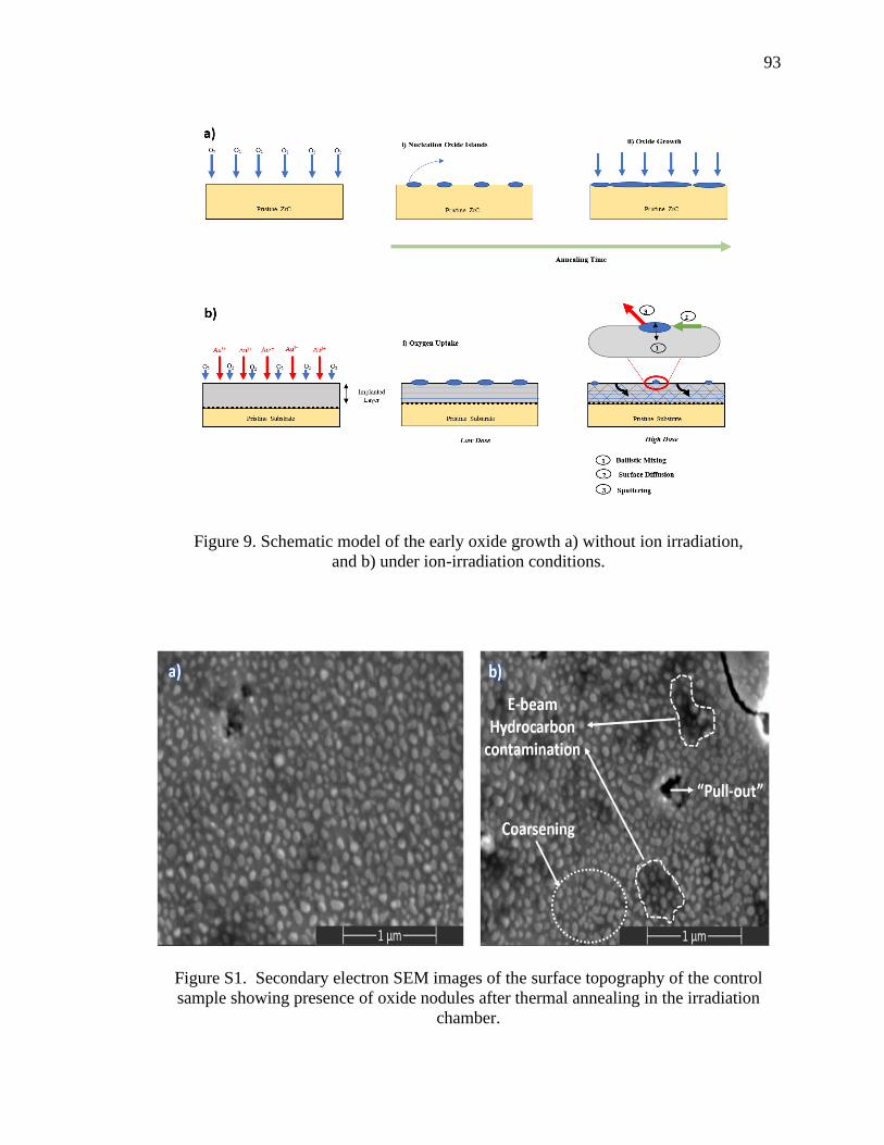
93
Figure 9. Schematic model of the early oxide growth a) without ion irradiation,
and b) under ion-irradiation conditions.
Figure S1. Secondary electron SEM images of the surface topography of the control
sample showing presence of oxide nodules after thermal annealing in the irradiation
chamber.

94
Figure S2. GIXRD patterns obtained from irradiated ZrC sample (ω=0.5o)
Figure S3. Conformal nanocrystalline ZrO2 layer formed on the top of the unirradiated
specimen after thermal annealing.

95
REFERENCES
[1] H. F. Jackson and W. E. Lee, “Properties and characteristics of ZrC,” R.J.M.
Konings (Ed.), Compr. Nucl. Mater., Elsevier, Oxford (2012), pp. 339-372
[2] Y. Katoh, G. Vasudevamurthy, T. Nozawa, and L. L. Snead, “Properties of
zirconium carbide for nuclear fuel applications,” J. Nucl. Mater., 441 (2013), pp.
718-742
[3] X. T. Shen, L. Liu, W. Li, and K. Z. Li, “Ablation behaviour of C/C-ZrC
composites in a solid rocket motor environment,” Ceram. Int., 41 (2015), pp.
11793-11803
[4] R. Ganter, R. J. Bakker, C. Gough, M. Paraliev, M. Pedrozzi, F. Le Pimpec, L.
Rivkin, A. Wrulich, “Nanosecond field emitted and photo-field emitted current
pulses from ZrC tips,” Nucl. Instruments Methods Phys. Res. Sect. A Accel.
Spectrometers, Detect. Assoc. Equip., 565 (2006), pp. 423-429
[5] B. Pierrat, M. Balat-Pichelin, L. Silvestroni, and D. Sciti, “High temperature
oxidation of ZrC-20%MoSi2 in air for future solar receivers,” Sol. Energy Mater.
Sol. Cells, 95 (2011), pp. 2228-2237
[6] G. Vasudevamurthy, T. W. Knight, E. Roberts, and T. M. Adams, “Laboratory
production of zirconium carbide compacts for use in inert matrix fuels,” J. Nucl.
Mater., 374 (2008), pp. 241-247
[7] R. Liu, Z. M. Xie, J. F. Yang, T. Zhang, T. Hao, X. P. Wang, Q. F. Fang, C. S.
Liu, “Recent progress on the R&D of W-ZrC alloys for plasma facing components
in fusion devices,” Nucl. Mater. Energy, 16 (2018), pp. 191–206
[8] D. Wongsawaeng, “Performance modeling of Deep Burn TRISO fuel using ZrC as
a load-bearing layer and an oxygen getter,” J. Nucl. Mater., 396 (2010), pp. 149-
158
[9] K. A. Terrani, “Accident tolerant fuel cladding development: Promise, status, and
challenges” J. Nucl. Mater., 501 (2018), pp. 13-30
[10] I. E. Porter, T. W. Knight, M. C. Dulude, E. Roberts, and J. Hobbs, “Design and
fabrication of an advanced TRISO fuel with ZrC coating,” Nucl. Eng. Des., 259
(2013), pp. 180–186

96
[11] R. Wright, J. Wright, and C. Cabet, “Material performance in helium-cooled
systems,” R.J.M. Konings (Ed.), Compr. Nucl. Mater., Elsevier, Oxford (2012),
Vol. 5, pp. 251-277
[12] J. Berka, T. Hlinčík, I. Víden, T. Hudský, and J. Vít, “The design and utilization of
a high temperature helium loop and other facilities for the study of advanced gas-
cooled reactors in the Czech Republic,” Prog. Nucl. Energy, 85 (2015), pp. 156-
163
[13] N. Sakaba, T. Furusawa, T. Kawamoto, Y. Ishii, and Y. Oota, “Short design
descriptions of other systems of the HTTR,” Nucl. Eng. Des., 233 (2004), pp. 147-
154
[14] H. Chang, Z. X. Wu, and H. J. Jia, “Experimental study on cryogenic adsorption of
methane by activated carbon for helium coolant purification of High-Temperature
Gas-cooled Reactor,” Ann. Nucl. Energy, 101 (2017), pp. 367-374
[15] S. Hamamoto, Y. Shimazaki, T. Furusawa, T. Nemoto, H. Inoi, and S. Takada,
“Investigation of chemical characteristics of primary helium gas coolant of HTTR
(high temperature engineering test reactor),” Nucl. Eng. Des., 271 (2014), pp. 487-
491
[16] V. Pauly, C. Tesch, J. Kern, M. Clark, D. Grierson, D.Singh, O. Ajayi, K.
Sridharan, “High-temperature tribological behavior of structural materials after
conditioning in impure-helium environments for high-temperature gas-cooled
reactor applications,” J. Nucl. Mater., 522 (2019), pp. 311-323
[17] G. Gutierrez, N.Toulhoat, N.Moncoffre, Y.Pipon, A.Maître, M.Gendre, A.Perrat-
Mabilon, “Thermal behaviour of xenon in zirconium carbide at high temperature:
Role of residual zirconia and free carbon,” J. Nucl. Mater., 416 (2011), pp. 94-98
[18] Y. Pipon, N. Toulhoat, N. Moncoffre, G. Gutierrez, A. Maître, and M. Gendre,
“Influence of the Oxygen content on the thermal migration of Xenon in ZrCxO1-x,”
J. Nucl. Mater., 440 (2013), pp. 546-552
[19] S. Agarwal, A. Bhattacharya, P. Trocellier, and S. J. Zinkle, “Helium induced
microstructure damage, nano-scale grain formation and helium retention behaviour
of ZrC,” Acta Mater., 163 (2019), pp. 14-27
[20] T. Yamaguchi, “Application of ZrO2 as a catalyst and a catalyst support,” Catal.
Today, 20 (1994), pp. 199-217
[21] M. V. Ganduglia-Pirovano, A. Hofmann, and J. Sauer, “Oxygen vacancies in
transition metal and rare earth oxides: Current state of understanding and
remaining challenges,” Surface Science Reports. 62 (2007), pp. 219-227

97
[22] S. Shimada and T. Ishil, “Oxidation Kinetics of Zirconium Carbide at Relatively
Low Temperatures,” J. Am. Ceram. Soc., 73 (1990), pp. 2804-2808
[23] S. Shimada, M. Yoshimatsu, M. Inagaki, and S. Otani, “Formation and
characterization of carbon at the ZrC/ZrO2 interface by oxidation of ZrC single
crystals,” Carbon, 36 (1998), pp. 1125-1131
[24] S. Shimada, “Oxidation and Mechanism of Single Crystal Carbides with
Formation of Carbon.,” J. Ceram. Soc. Japan, 109 (2001), pp. 33-42
[25] C. Gasparrini, R. J. Chater, D. Horlait, L. Vandeperre, and W. E. Lee, “Zirconium
carbide oxidation: Kinetics and oxygen diffusion through the intermediate layer,”
J. Am. Ceram. Soc., 101 (2018), pp. 2638-2652
[26] C. Gasparrini, R. Podor, D. Horlait, R. Chater, and W. E. Lee, “Zirconium Carbide
Oxidation: Maltese Cross Formation and Interface Characterization,” Oxid. Met.,
88 (2017), pp. 509–519
[27] G. A. Rama Rao and V. Venugopal, “Kinetics and mechanism of the oxidation of
ZrC,” J. Alloys Compd., 206 (1994), pp. 237-242
[28] D. Gozzi, M. Montozzi, and P. L. Cignini, “Oxidation kinetics of refractory
carbides at low oxygen partial pressures,” Solid State Ionics, 123 (1999), pp. 11-18
[29] A. Bellucci, D. Gozzi, T. Kimura, T. Noda, and S. Otani, “Zirconia growth on
zirconium carbide single crystals by oxidation,” Surf. Coatings Technol., 197
(2005), pp. 294–302
[30] B. Wei, D. Wang, Y. Wang, H. Zhang, S. Peng, C. Xu, G. Song and Yu Zhou.,
“Corrosion kinetics and mechanisms of ZrC1-x ceramics in high temperature water
vapor,” RSC Adv. 8 (2018), pp. 18163-74
[31] G.Gutierrez, N.Toulhoat, N.Moncoffre, Y.Pipon, N.Djourelov, A.Maître,
M.Gendre, P.Nedelec, “High temperature annealing of Xe implanted ZrC0.95O0.05
investigated by RBS, TEM and PAS-DBS,” Prog. Nucl. Energ, 57 (2012), pp. 57-
61
[32] X. Iltis, F. Lefebvre, and C. Lemaignan, “Microstructural study of oxide layers
formed on Zircaloy-4 in autoclave and in reactor Part i: Impact of irradiation on
the microstructure of the zirconia layer,” J. Nucl. Mater., 224 (1995), pp. 109-120
[33] A. Garner, F. Baxter, P. Frankel, M. Topping, A. Harte, T. Slater, P. Tejland, J.
Romero, E. Darby, A. Cole-Baker, M. Gass, M. Preuss, “Investigating the Effect
of Zirconium Oxide Microstructure on Corrosion Performance: A Comparison
between Neutron, Proton, and Nonirradiated Oxides,” in Zirconium in the Nuclear
Industry: 18th International Symposium, ASTM STP1597, R. J. Comstock and A.
T. Motta, Eds., ASTM International, West Conshohocken, PA, 2018, pp. 491–523

98
[34] Y. Zhang, M. L. Crespillo, H. Xue, K. Jin, C. H. Chen, C. L. Fontana, J. T.
Graham, W. J. Weber, “New ion beam materials laboratory for materials
modification and irradiation effects research,” Nucl. Instruments Methods Phys.
Res. Sect. B Beam Interact. with Mater. Atoms, 338 (2014), pp. 19-30
[35] M. L. Crespillo, J. T. Graham, Y. Zhang, and W. J. Weber, “In-situ luminescence
monitoring of ion-induced damage evolution in SiO2 and Al2O3,” J. Lumin., 172
(2016), pp. 208-218
[36] M. L. Crespillo, J. T. Graham, Y. Zhang, and W. J. Weber, “Temperature
measurements during high flux ion beam irradiations,” Rev. Sci. Instrum., 87
(2016), pp. 024902
[37] J. F. Ziegler, M. D. Ziegler, and J. P. Biersack, “SRIM - The stopping and range of
ions in matter (2010),” Nucl. Instruments Methods Phys. Res. Sect. B Beam
Interact. with Mater. Atoms, 268 (2010), pp. 1818-1823
[38] M. J. Zheng, I. Szlufarska, and D. Morgan, “Ab initio prediction of threshold
displacement energies in ZrC,” J. Nucl. Mater., 471 (2016), pp. 214–219
[39] R. E. Stoller, M. B. Toloczko, G. S. Was, A. G. Certain, S. Dwaraknath, and F. A.
Garner, “On the use of SRIM for computing radiation damage exposure,” Nucl.
Instruments Methods Phys. Res. Sect. B Beam Interact. with Mater. Atoms, 310
(2013), pp. 75–80
[40] Y. Zhang, M. A Tunes, M. L Crespillo, F. Zhang, W. L. Boldman, P. D Rack, L.
Jiang, C. Xu, G. Greaves, S. E. Donnelly, “Thermal stability and irradiation
response of nanocrystalline CoCrCuFeNi high-entropy alloy,” Nanotechnology, 30
(2019), pp. 294004
[41] G. S. Was, Fundamentals of radiation materials science: Metals and alloys,
second edition. 2016.
[42] S. J. Zinkle and G. S. Was, “Materials challenges in nuclear energy,” Acta
Mater.,61 (2013), pp. 735-758
[43] ASTM, “ASTM C373-14 Standard Test Method for Water Absorption, Bulk
Density, Apparent Porosity, and Apparent Specific Gravity of Fired Whiteware
Products,” Astm C373-88, 1999
[44] F. Réjasse, O. Rapaud, G. Trolliard, O. Masson, and A. Maître, “Experimental
investigation and thermodynamic evaluation of the C–O–Zr ternary system,” RSC
Adv., 100 (2016) pp. 100122-35

99
[45] M. L. Jenkins and M. A. Kirk, Characterization of Radiation Damage by
Transmission Electron Microscopy, Series in Microscopy in Materials Science,
Institute of Physics Publishing (2001)
[46] H. L. Brey and H. G. Olson, “The Fort St. Vrain high temperature gas-cooled
reactor. II. Helium circulators,” Nucl. Eng. Des., 53 (1979), pp. 125-131
[47] R. Bès, S. Gavarini, N. Millard-Pinard, S. Cardinal, A. Perrat-Mabilon, C.
Peaucelle, T. Douillard, “Influence of crystallographic orientation on the early
stages of oxidation of polycrystalline titanium nitride,” J. Nucl. Mater., 427
(2012), pp. 415-417
[48] S. Gavarini, R. Bes, N. Millard-Pinard, S. Cardinal, C. Peaucelle, A. Perrat-
Mabilon, V. Garnier, and C. Gaillard, “A comparative study of TiN and TiC:
Oxidation resistance and retention of xenon at high temperature and under
degraded vacuum,” J. Appl. Phys., 109 (2011), pp. 014906
[49] J. Baillet, S. Gavarini, N.Millard-Pinard, V. Garnier, C. Peaucelle, X. Jaurand, S.
Cardinal, A. Duranti, C. Bernard, R. Rapegno, L. Dernoncourt, T. De Echave,
“Influence of grain size and microstructure on oxidation rate and mechanism in
sintered titanium carbide under high temperature and low oxygen partial pressure,”
J. Eur. Ceram. Soc., 36 (2016), pp. 3099-3111
[50] R. V. Zucker, G. H. Kim, W. Craig Carter, and C. V. Thompson, “A model for
solid-state dewetting of a fully-faceted thin film,” Comptes Rendus Physique.14
(2013), pp. 564-577
[51] R. Lo Savio, L. Repetto, P. Guida, E. Angeli, G. Firpo, A. Volpe, V. Lerardi, U.
Valbusa , “Control of the micrometric scale morphology of silicon nanowires
through ion irradiation-induced metal dewetting,” Solid State Commun., 240
(2016), pp. 41-45
[52] L. Luo, Y. Kang, J. C. Yang, and G. Zhou, “Nucleation and growth of oxide
islands during the initial-stage oxidation of (100)Cu-Pt alloys,” J. Appl. Phys., 117
(2015), pp. 065305
[53] G. Zhou and J. C. Yang, “ Formation of Quasi-One-Dimensional Cu2O Structures
by in situ Oxidation of Cu(100) ,” Phys. Rev. Lett., 89 (2002), pp. 106101
[54] G. Zhou and J. C. Yang, “Initial oxidation kinetics of Cu(100), (110), and (111)
thin films investigated by in situ ultra-high-vacuum transmission electron
microscopy,” J. Mater. Res., 20 (2005), pp. 1684-1694
[55] G. Zhou, “Nucleation thermodynamics of oxide during metal oxidation,” Appl.
Phys. Lett., 94 (2009), pp. 201905

100
[56] W. Ma, F. W. Herbert, S. D. Senanayake, and B. Yildiz, “Non-equilibrium
oxidation states of zirconium during early stages of metal oxidation,” Appl. Phys.
Lett., 106 (2005), pp. 101603
[57] S. Shimada, “A thermoanalytical study on the oxidation of ZrC and HfC powders
with formation of carbon,” Solid State Ionics, 149 (2002), pp. 319-326
[58] R. C. Garvie, “The occurrence of metastable tetragonal zirconia as a crystallite size
effect,” J. Phys. Chem., 69 (1965), pp. 1238-1243
[59] Y. Kanno, “Stability of metastable tetragonal ZrO2 in compound powders and
nucleation arguments,” J. Mater. Sci., 25 (1990), pp. 1987–1990
[60] S. Shukla and S. Seal, “Mechanisms of room temperature metastable tetragonal
phase stabilisation in zirconia,” Int. Mater. Rev., 50 (2005), pp. 45-64
[61] T. Mitsuhashi, M. Ichihara, and U. Tatsuke, “Characterization and Stabilization of
Metastable Tetragonal ZrO2,” J. Am. Ceram. Soc., 57 (1974), pp. 97-101
[62] J. M. Costantini, F. Beuneu, and W. J. Weber, “Radiation damage in cubic-
stabilized zirconia,” J. Nucl. Mater., 440 (2013), pp. 508-514
[63] K. E. Sickafus, Hj. Matzke, Th. Hartmann, K.Yasuda, J.A.Valdez, P.Chodak III,
R.A.Verrall, “Radiation damage effects in zirconia,” J. Nucl. Mater., 274 (1999),
pp. 66-77
[64] D. S. Aidhy, Y. Zhang, and W. J. Weber, “Radiation damage in cubic ZrO2 and
yttria-stabilized zirconia from molecular dynamics simulations,” Scr. Mater., 98
(2015), pp. 16-19
[65] E. Zarkadoula, R. Devanathan, W. J. Weber, M. A. Seaton, I. T. Todorov, K.
Nordlund, M. T. Dove, and K. Trachenko, “High-energy radiation damage in
zirconia: Modeling results,” J. Appl. Phys., 115 (2014), pp. 083507
[66] P. Krasnochtchekov, R. S. Averback, and P. Bellon, “Precipitate stability and
morphology in irradiation environments,” JOM, 59 (2007), pp 46–50
[67] Allen T.R., Was G.S. (2007) Radiation-enhanced diffusion and radiation-
induced segregation. In: Sickafus K.E., Kotomin E.A., Uberuaga B.P. (eds)
Radiation Effects in Solids. NATO Science Series, vol 235. Springer,
Dordrecht
[68] W. Hu, J. Xiang, S. Liu, Y. Zhang, C. Chen, P. Wang, H. Wang, B. Xu, J. He, D.
Yu, Y. Tian, Z. Liu “Low-temperature diffusion of oxygen through ordered carbon
vacancies in Zr2Cx: the formation of ordered Zr2CxOy,” Inorg. Chem., 51 (2012),
pp. 5164-5172

101
[69] M. Schuhmacher and P. Eveno, “Oxygen diffusion in titanium carbide,” Solid
State Ionics, 12 (1984), pp. 263-270
[70] J.Baillet, S.Gavarini, N.Millard, Pinard, V. Garnier, C. Peaucelle X. Jaurand, A.
Duranti, C. Bernard, R. Rapegno, S. Cardinal, L. Escobar Sawa, T.De Echave, B.
Lanfant, Y.Leconte, “Surface damage on polycrystalline β-SiC by xenon ion
irradiation at high fluence,” J. Nucl. Mater., 503 (2018), pp. 140-150
[71] U. Brossmann, R. Würschum, U. Södervall, and H. E. Schaefer, “Oxygen diffusion
in ultrafine grained monoclinic ZrO2,” J. Appl. Phys., 85 (1999), pp. 7646
[72] P. D. Edmondson, Y. Zhang, F. Namavar, C. M. Wang, Z. Zhu, and W. J. Weber,
“Defect- and strain-enhanced cavity formation and Au precipitation at nano-
crystalline ZrO2/SiO2/Si interfaces,” Nucl. Instruments Methods Phys. Res. Sect. B
Beam Interact. with Mater. Atoms, 269 (2011), pp. 126-132

102
III. SEQUENTIAL ION-ELECTRON IRRADIATION OF ZIRCONIUM
CARBIDE CERAMICS: MICROSTRUCTURAL ANALYSIS
Raul Floreza, Xiaoqing Heb,c, Tommi A. Whitec,d, Miguel L. Crespilloe, Gregory Hilmasf,
William Fahrenholtzf, Joseph Grahama,f*
a. Nuclear Engineering Program, Missouri University of Science and Technology,
65409 Rolla, MO, United States
b. Electron Microscopy Core, University of Missouri, 65211 Columbia, MO,
United States
c. Department of Mechanical and Aerospace Engineering, University of Missouri, 65211
Columbia, MO, United States
d. Department of Biochemistry, University of Missouri, 65211, Columbia, MO,
United States
e. Department of Material Science and Engineering, University of Tennessee, 37996
Knoxville, TN, United States
f. Department of Materials Science and Engineering, Missouri University of Science and
Technology, 65409 Rolla, MO, United States
ABSTRACT
Zirconium Carbide (ZrCx) was irradiated with 10 MeV Au3+ ions to a dose of 10
displacements per atoms (dpa) and subsequently with 300 keV electrons in a transmission
electron microscope (TEM). After ion irradiation, dislocation loops were observed in the
microstructure and an increase in the number of carbon vacancies was revealed by Raman
spectroscopy. Grazing incidence X-ray diffraction (GIXRD) analysis showed that neither
amorphization nor oxidation occurred during ion irradiation of the specimen. Subsequent
electron irradiation of the pre-implanted ZrCx foil led to formation of nanosized tetragonal
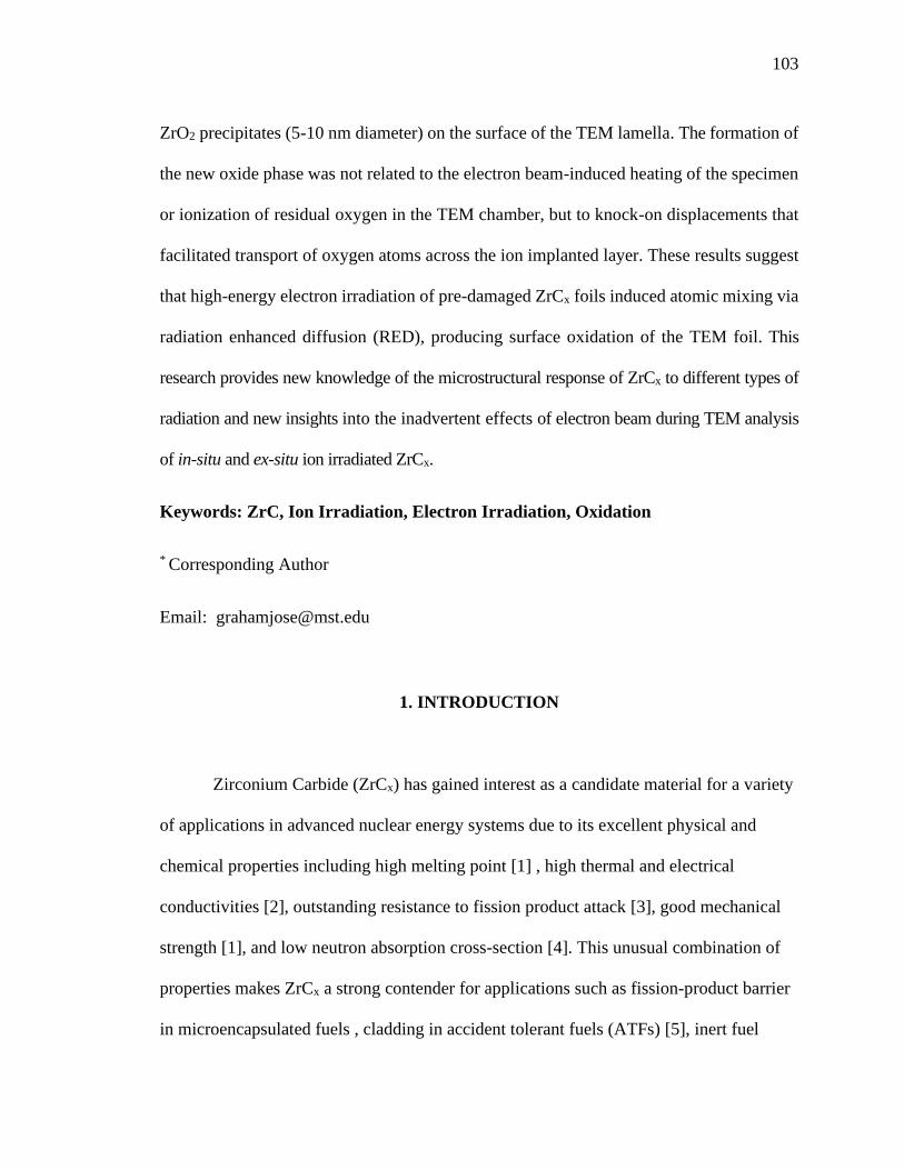
103
ZrO2 precipitates (5-10 nm diameter) on the surface of the TEM lamella. The formation of
the new oxide phase was not related to the electron beam-induced heating of the specimen
or ionization of residual oxygen in the TEM chamber, but to knock-on displacements that
facilitated transport of oxygen atoms across the ion implanted layer. These results suggest
that high-energy electron irradiation of pre-damaged ZrCx foils induced atomic mixing via
radiation enhanced diffusion (RED), producing surface oxidation of the TEM foil. This
research provides new knowledge of the microstructural response of ZrCx to different types of
radiation and new insights into the inadvertent effects of electron beam during TEM analysis
of in-situ and ex-situ ion irradiated ZrCx.
Keywords: ZrC, Ion Irradiation, Electron Irradiation, Oxidation
* Corresponding Author
Email: [email protected]
1. INTRODUCTION
Zirconium Carbide (ZrCx) has gained interest as a candidate material for a variety
of applications in advanced nuclear energy systems due to its excellent physical and
chemical properties including high melting point [1] , high thermal and electrical
conductivities [2], outstanding resistance to fission product attack [3], good mechanical
strength [1], and low neutron absorption cross-section [4]. This unusual combination of
properties makes ZrCx a strong contender for applications such as fission-product barrier
in microencapsulated fuels , cladding in accident tolerant fuels (ATFs) [5], inert fuel

104
matrix in Gen-IV fast nuclear reactors [6], and plasma facing material (PFM) in fusion
reactors [7]. In nuclear reactor systems, ZrCx will be exposed to different types of
radiation fields (gamma, neutron, ion and beta particles), which can change the
microstructure of ZrCx during reactor operation. The microstructural changes induced by
radiation damage affect the properties of ZrCx and its performance in the nuclear reactor.
This could eventually impact the safety of the reactor under operation and accident
conditions. Consequently, it is crucial to understand the behavior of ZrCx under
irradiation conditions for its successful implementation in the next generation of nuclear
energy systems.
Numerous studies have been conducted to investigate the effects of irradiation on
ZrCx [8-14]. Most of the previous work has aimed to identify and quantify the
microstructural defects in ion irradiated specimens as a function of the ion type, dose,
temperature, and stoichiometry. The current damage mechanism map indicates that the
radiation response of ZrCx at temperatures relevant to the operation of nuclear reactors
(20–1073 K) is driven by interstitial clustering [11]. This has been confirmed by
transmission electron microscopy (TEM) analysis of irradiated samples, showing the
progressive evolution from “black-dot” defects, to dislocation loops, to entangled
dislocation networks with increasing irradiation dose [8], [9]. In addition to the
microstructural defects, a secondary oxide phase is usually found during TEM analysis of
irradiated ZrCx. The oxide phase appears as nanosized precipitates, which are distributed
across the surface of the TEM lamella. Gan et al. [15] were the first ones to report the
formation of the new phase in ZrC irradiated with 1 MeV Kr2+ ions at the Intermediate
Voltage Electron Microscope (IVEM) facility. They observed diffraction rings in the

105
selected area electron diffraction (SAED) patterns for samples irradiated at 300 K and
1073 K. The authors concluded that the diffraction rings were produced by nanosized
precipitates having face centered cubic (FCC) symmetry with a lattice parameter of 0.506
nm (~8% larger than ZrC). Gosset et al. [9], [10] also reported the formation of a
secondary phase after irradiation of ZrC with 4 MeV Au3+ ions at room temperature
(RT). Based on the indexing of the diffraction rings, the secondary phase was identified
as tetragonal ZrO2 (a=3.61 Å and c=5.19 Å). Additionally, dark field images acquired
with part of the most intense diffraction ring revealed a high density of nanometric
precipitates located at the surface of the specimen. Recently, Ulmer et al. [16] also found
that oxide nanoprecipitates were formed during in-situ irradiation of ZrC with
1 MeV Kr2+ ions at temperatures within 20-1073 K. The indexing of the rings was
consistent with a 0.506 nm lattice parameter FCC structure, which is close to that of
cubic ZrO2. Interestingly, Ulmer also noted that the diffraction rings appeared in samples
irradiated at all temperatures, except 300 K and 473 K. This result contradicts Gan’s
work that found oxide precipitates in samples irradiated at 300 K. The discrepancy is
surprising considering that both authors conducted the irradiations experiments under
similar conditions (1 MeV Kr2+ at 300 K at the IVEM facility).
Although the formation of oxide precipitates seems to be one of the most
prominent radiation effects in ion irradiated ZrCx, the mechanism underlying their
formation is not fully understood. Given the high thermodynamic driving force for
oxidation of ZrCx [17], Gosset et al. [9] suggested that the precipitates were formed by
radiation-enhanced oxidation during ion implantation of ZrC foils. However, the
experimental evidence supporting this hypothesis is still inconclusive. For example, if

106
radiation-enhanced oxidation was the prevalent mechanism of oxide formation, a
systematic variation in the intensity of the diffraction rings would occur as the irradiation
dose increased. Yet, no systematic changes in the selected area electron diffraction
(SAED) patterns were observed for ZrC specimens irradiated with Kr-ions at different
doses [15], [16]. Furthermore, the hypothesis of radiation-enhanced oxidation also fails
to explain why oxide precipitates were formed in samples irradiated at cryogenic
temperatures, but not in those irradiated at RT [16]. This result is unexpected considering
that the diffusion of atoms and defects is significantly lower at cryogenic temperatures
than at RT. Another aspect of the oxidation process that needs further explanation is that
crystalline oxide nanoprecipitates formed only during in-situ for ion irradiated ZrC
specimens. For bulk sample irradiation, the studies showed that thin oxide layers formed
in ZrC after irradiation. The oxide layer was amorphous in specimens irradiated at RT
[18] and crystalline in those irradiated at a high temperature (1073 K) [19]. These
observations lead to the question: Why does the oxidation behavior differ between
samples irradiated ex-situ and in-situ, if the mechanism driving the transformation is the
same?. The absence of systematic changes of the SAED patterns in stand-alone studies
and the inconsistencies that arise when comparing the results from different research
groups, suggest that extrinsic factors might play a role in the formation of the oxide
precipitates during in-situ ion-irradiation of ZrC.
A major difference between in-situ and ex-situ ion irradiations is that energetic
electrons are simultaneously used during in-situ ion irradiations. The concurrent use of
electrons during ion irradiation can produce unintended effects, which could potentially
modify the microstructure of the material being investigated [21]. Previous work on

107
transition metal carbides indicated that prolonged exposure to energetic electrons in the
TEM can produce elemental segregation through the foil. Thus, it is possible that the
electrons used for imaging during in-situ ion irradiations can also be involved in the
formation of ZrO2 nanoprecipitates on ion implanted ZrC specimens. Therefore, the goal
of this study was to investigate the effects of electron irradiation during TEM
examination of an ion- irradiated ZrC foil to study possible segregation effects. Direct
evidence is provided that e-beam exposure produces surface oxidation of ion irradiated
ZrC foil leading to possible reaction schemes.
2. MATERIALS AND METHODS
2.1. SAMPLE PREPARATION
The following section describe the methodology used for the preparation of the
specimens used in this work.
2.1.1. Synthesis of ZrO2 precursor. High purity ZrO2 powders with low Hf
content were synthesized by a precipitation method using ZrCl4 powder (Reactor grade,
>99.5% metal basis, Alfa Aesar) and NH4OH (28 wt%, Alfa Aesar) as starting materials.
Precipitation was induced by dropwise addition of 28 wt% NH4OH to 0.4 M ZrCl4
solution until the pH reached 10. After aging for 30 minutes under strong stirring with a
magnetic stir bar, the precipitate was filtered and washed with an excess of deionized
water to remove chloride ions. The hydrous cake was then dried at 120 oC overnight.
Afterwards, the powder was calcined in a convection oven at 700 oC for 4 hours to

108
produce ZrO2. The obtained powder was lightly ground with a mortar and pestle and
passed through a 60 mesh sieve.
2.1.2. Synthesis of ZrC powder. The synthesized ZrO2 and carbon black (BP-
1100, Cabot Corporation, Alpharetta, GA, USA) were batched with a molar ratio of
ZrO2:C=1:3 based on the stoichiometry of Reaction 1 and then ball-milled using zirconia
milling media and acetone for 24 hours. Afterwards, the slurry was dried by rotary
evaporation (Rotavapor R-124; Buchi, Flawil, Germany) at a temperature of 80o C, under
low vacuum (~27 kPa), and a rotation speed of 120 rpm. The dried powder was passed
through a 50-mesh sieve and pelletized by uniaxial pressing before carbothermal
reduction.
Solid state carbothermal reduction was conducted in a graphite element furnace
(3060-FP20, Thermal Technology, Santa Rosa, CA, USA) under vacuum conditions. The
mixed powder was heated from room temperature to 1800o C at a heating rate of
10oC/min, and dwell time of 6 hours.
𝑍𝑟𝑂2 + (2 + 𝑥 − 𝑦)𝐶 → 𝑍𝑟(𝐶𝑥, 𝑂𝑦) + (2 − 𝑦)𝐶𝑂 ↑ (1)
2.1.3. Densification. A billet of ZrC was prepared by hot-pressing the synthesized
ZrC powder in a 25.4 mm cylindrical graphite die lined with BN-coated (SP-180 Cerac,
Milwaukie, WI) graphite foil (2010-A; Mineral Seal Corp, Tucson, Arizona). The powder
was loaded into the die and cold compacted in a uniaxial press at ~2MPa. The powder
was then heated under vacuum to 1600 0C with an average heating rate of 20 0C/min. At
that time, the furnace was backfilled with helium and a uniaxial pressure of 32 MPa was
applied. The furnace was then heated at 50 0C/min to 2200 0C. After 90 min at 2200°C,

109
the furnace was cooled at ~50 0C/min. The load was removed when the die temperature
dropped below 1600 0C.
Following densification, the specimens for microscopy and ion irradiations were
cut parallel to the hot pressing direction with a slow-speed diamond saw. The surface of
the ZrC foils were then polished to a 0.25 μm mirror-finish using successively finer
diamond abrasives. After polishing, the specimens were ultrasonically cleaned with
ethanol for 15 min at room temperature.
2.2. ION IMPLANTATION
A rectangular ZrC foil (12 x 4 mm) was irradiated in the Ion Beam Materials
Laboratory (IBML UT-ORNL) at the University of Tennessee, Knoxville [20] with 10
MeV Au3+ ions at room temperature using a 3.0 MV tandem accelerator. The central
region of the ZrC foil (7x4 mm) was irradiated to a dose of 10 dpa. The ion beam was
defocused and rastered in the horizontal and vertical directions with the aim of producing
a region that was homogeneously irradiated. Beam homogeneity was verified by ion-
induced luminescence from quartz targets and was found to be within 10% throughout
the irradiated area [21]. The ion flux was set at 7 ×1011 cm-2 s-1. Low beam current
densities in the range of 5 nA mm-2 were used to reduce any undesired effects or charge
accumulation on the samples [22]. The vacuum chamber pressure was below 10−7 torr
during ion irradiation. The Stopping and Range of Ions in Matter binary collision
approximation (BCA) code 2013 version (SRIM-2013) [23] was used to estimate the
displacement damage depth profile. Cascades were performed in quick-cascade mode
(simple Kinchin and Pease model) assuming a density of 6.71 g/cm3 for ZrC and

110
threshold displacement energies of 37 eV for Zr and 16 eV for C [24]. To compare ion
and neutron irradiation results, the use of the quick Kinchin–Pease option in SRIM to
compute radiation damage exposure has been recommended within the nuclear
community [25]. The damage profile estimated from SRIM is determined by the sum of
the predicted vacancy concentrations (using 'Knock-Ons' from Au ions and 'Vacancies'
from target elements of Zr and C, together with the replacement collisions [26].
Assuming a bulk ZrC sample, the predicted damage profile in displacements per atom
(dpa) and the implanted Au ion profile are shown in Figure 1. The peak dose under 10
MeV Au irradiation is located around 1000 nm. The conversion factor from ion fluence
(1014 cm−2) to local dose in the ZrC foil under quick simulation was 0.8343 dpa.
Irradiations were performed with Au ions because of their relatively inert nature and
large nuclear stopping cross section, which enables a high damage rate per incident ion
while minimizing artifacts induced by the injected ions. The beam energy of 10 MeV was
chosen to obtain a relatively flat profile to a depth of 1 µm without appreciable effects of
implanted Au ions (Figure 1). Moreover, intermediate energy heavy ion irradiations
produce a displacement cascade density and morphology more similar to fission neutrons
than irradiation using light ions, which produces a more sparse sub-cascade morphology
[27].
2.3. MATERIAL CHARACTERIZATION
The following subsections presents detailed information about the experimental
techniques that were used to investigate the specimens.

111
2.3.1. Density and Chemical Analysis. The bulk density of the hot-pressed billet
was measured by the Archimedes’ method performed according to ASTM C73 using
distilled water as the immersing medium, [28]. The relative density was calculated by
dividing the Archimedes’ density by the estimated theoretical density of ZrC (𝜌=6.71
g/cm3). Chemical analyses for carbon, oxygen and nitrogen content were conducted by
the direct combustion method using infrared absorption detection. Carbon (CS600; Leco,
St. Joseph, MI), oxygen and nitrogen (TC500; Leco, St. Joseph, MI) contents were
measured by grinding part of the dense specimen to ~200 mesh. Three measurements
were conducted for each element to establish repeatability.
2.3.2. Grazing Incidence X-Ray Diffraction (GIXRD). Grazing incidence X-ray
diffraction measurements were performed to evaluate structural modifications in the near
surface region following ion irradiation. GIXRD profiles were collected on a
PANanlytical X’Pert Pro Multipurpose Diffractometer (MPD) fitted with a Cu X-ray tube
and an X’Celerator detector. Diffraction patterns were acquired in grazing incidence
geometry over the 2θ range 25-900 with a step size of 0.030 and counting time of 0.5 s at
each step. The scans were recorded at several incident angles between 0.5 and 50 in order
to probe microstructural changes at different mean penetration depths from 0.6 to 1.5 µm.
X-ray tube operation conditions were 40 kV and 40 mA.
2.3.3. Raman Spectroscopy. Raman measurements were collected using a
HORIBA Jobin Yvon LabRAM ARAMIS microRaman spectrometer (Horiba, Edison,
NJ). The specimens were excited by a 632 nm He/Ne laser focused to a spot 2-3 µm in
size on the sample using a 50x microscope objective lens. Raman spectra were acquired
in the backscattering geometry. The laser power was below 2 mW to prevent local

112
heating of the sample. Five spectra were taken from each specimen, with all
measurements conducted at room temperature.
2.3.4. Electron Microscopy. A TEM lamella specimen was lifted out from the
center of the ion irradiated ZrC sample and mounted onto a copper Omniprobe TEM grid.
The TEM sample was prepared in a dual Focused Ion Beam-Scanning Electron
Microscope (FIB-SEM SciosTM DualBeamTM, FEI, Hillsboro, Oregon). A 15 μm
(width) × 10 μm (depth) rectangular lamella was then further thinned to electron
transparency by the FIB (~50 nm). The TEM lamella was investigated using a FEI Tecnai
TF30-FEG STwin STEM working at 300 kV. Bright field (BF) micrographs were
acquired to characterize the microstructure of the pristine and ion irradiated areas of the
specimen. In addition, energy dispersive X-ray spectroscopy (EDX) and electron energy
loss spectroscopy) (EELS) were used to characterize the element composition of the ion
implanted layer. For the electron irradiation experiments, the beam was stabilized at 9.5
A/cm2 and the column pressure remained at 1.18×10⁻⁵ Pa (8.9×10⁻⁸ torr). A beam
illumination area of 1.25 μm in diameter was used for e-beam irradiations. SAED
patterns were collected at various times to investigate the microstructural evolution
during electron irradiations. Centered dark field images were also captured using a
portion of the ring structure visible in the SAED patterns for the diffracted beam.

113
3. RESULTS
3.1. DENSITY AND CHEMICAL ANALYSIS
The as-sintered ZrC pellet had a relative density of 95%. The carbon, oxygen and
nitrogen contents were 11.53, 0.821, and 0.0251 wt %, respectively.
3.2. GRAZING INCIDENCE X-RAY DIFFRACTION
Figure 2a) shows survey GIXRD patterns obtained from the as-sinetered ZrC
specimen. The patterns were acquired at ω values of 0.5, 1, 1.5, 3 and 5o to probe
microstructural changes from a layer on the surface of the specimen that was ~2.0 µm
thick. This thickness was selected because it corresponded to the range of the 10 MeV
Au3+ ions used in this work (see Figure 1). At all ω values, ZrCx with Fm3̅m crystal
structure (JCPDF card 35-0784) was the only phase detected and no extra peaks were
apparent.
GIXRD patterns were also acquired from the irradiated specimens as shown in Figure
2b. No new peaks were observed in any of the diffraction patterns. The irradiated specimen
only exhibited the expected peaks for ZrC at all ω values. Consequently, extensive
formation of ZrO2 did not occur during heavy ion irradiation of ZrC. Peak broadening and a
decrease in the peak intensity were observed upon ion irradiation. These concurrent changes
were indicative of structural distortion and heterogeneous microstrain produced by the
radiation induced defects. No significant peak shifts were observed before and after
irradiation, indicating low volumetric swelling of the ion irradiated ZrC.
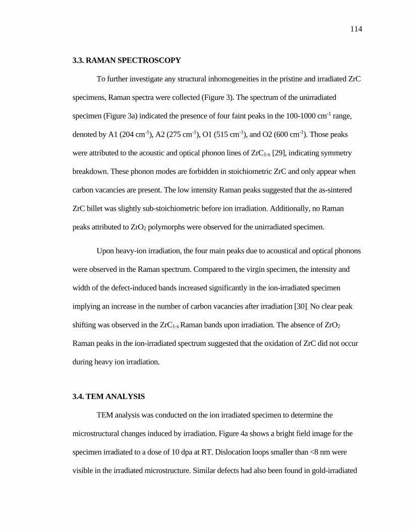
114
3.3. RAMAN SPECTROSCOPY
To further investigate any structural inhomogeneities in the pristine and irradiated ZrC
specimens, Raman spectra were collected (Figure 3). The spectrum of the unirradiated
specimen (Figure 3a) indicated the presence of four faint peaks in the 100-1000 cm-1 range,
denoted by A1 (204 cm-1), A2 (275 cm-1), O1 (515 cm-1), and O2 (600 cm-1). Those peaks
were attributed to the acoustic and optical phonon lines of ZrC1-x [29], indicating symmetry
breakdown. These phonon modes are forbidden in stoichiometric ZrC and only appear when
carbon vacancies are present. The low intensity Raman peaks suggested that the as-sintered
ZrC billet was slightly sub-stoichiometric before ion irradiation. Additionally, no Raman
peaks attributed to ZrO2 polymorphs were observed for the unirradiated specimen.
Upon heavy-ion irradiation, the four main peaks due to acoustical and optical phonons
were observed in the Raman spectrum. Compared to the virgin specimen, the intensity and
width of the defect-induced bands increased significantly in the ion-irradiated specimen
implying an increase in the number of carbon vacancies after irradiation [30]. No clear peak
shifting was observed in the ZrC1-x Raman bands upon irradiation. The absence of ZrO2
Raman peaks in the ion-irradiated spectrum suggested that the oxidation of ZrC did not occur
during heavy ion irradiation.
3.4. TEM ANALYSIS
TEM analysis was conducted on the ion irradiated specimen to determine the
microstructural changes induced by irradiation. Figure 4a shows a bright field image for the
specimen irradiated to a dose of 10 dpa at RT. Dislocation loops smaller than <8 nm were
visible in the irradiated microstructure. Similar defects had also been found in gold-irradiated

115
ZrCx to fluences above 1015 cm--2 [9],[16]. After irradiation to 10 dpa at RT, SAED showed
that the Fm3̅m crystal structure of ZrCx remained unchanged (Figure 5a), corroborating the
high radiation-induced- amorphization (RIA) resistance of this material. Aside from ZrC, no
distinguishable diffraction signals of nanocrystalline ZrO2 or other secondary phases were
apparent in the SAED pattern acquired immediately after focusing the electron beam in the
ion-irradiated area. However, diffuse rings started to appear in SAED patterns when the
analyzed area was continuously exposed to the electron beam. This indicated that
microstructural modifications occurred in the analyzed specimen during TEM examination.
3.4.1. Electron Beam Irradiations. The effect of the electron irradiation beam in
irradiated and unirradiated ZrC grains is discussed next.
3.4.1.1. Ion irradiated ZrC grain. To further evaluate the effects of the e-beam on
the TEM specimen, in situ electron irradiation experiments were conducted over different
areas of the irradiated sample. Figure 5 shows a sequence of SAED patterns acquired at
selected times during the electron irradiation of a ZrC grain implanted with 10 MeV Au3+
ions. The area selected for this experiment was located about 1 µm from the top surface
and far away from grain boundaries where defect-denuded zones are usually observed.
The first diffraction pattern (Figure 5a) was obtained immediately after focusing the
electron beam in the ion-irradiated area and was comprised only of ZrC diffraction spots.
No extra diffraction rings or spots were apparent in the SAED pattern at the beginning of
the e-beam irradiation. After 30 minutes of exposure to the electron beam, weak
diffraction rings were observed in the SAED pattern as illustrated in Figure 5b. Increased
beam time resulted in a sharpening of the diffraction rings (Figure 5c). From their relative
radii, the diffraction rings did not correspond to interplanar distances of the initial ZrC

116
cubic phase. Examination of the powder diffraction file database showed that the
interplanar distances matched well with tetragonal zirconia (t-ZrO2 , space group
P42/nmc, tetragonal crystal system with lattice parameters a=3.6 Å and b=5.19 Å)
according to the card PDF 050 1089. HRTEM and the corresponding Fast Fourier
Transform (FFT) images acquired from the electron irradiated area (Figure 6), further
confirmed the existence of t-ZrO2. The FFT pattern corresponding to the electron irradiated
area (Figure 6b) showed incomplete rings of dots that were indicative of nanocrystalline t-
ZrO2. The discretization of the diffraction rings suggested that the nanoprecipitates were
formed by homogeneous nucleation and were randomly oriented with respect to the ZrC
matrix. The oxide crystallite analyzed is indicated by the red box in Figure 6a. The
acquired FFT pattern (Figure 6c) matched well with the simulated diffraction pattern of
t-ZrO2.
In order to investigate the distribution of the t-ZrO2 precipitates in the specimen,
dark field (DF) images were acquired on the e-beam irradiated area. Figure 5d shows a DF
micrograph taken from a selected part of the diffraction ring as indicated by the circled zone in
the inset diffraction pattern. A high density of bright precipitates distributed throughout the
ZrC matrix could be observed upon e-beam irradiation. The t-ZrO2 precipitates had equiaxial
shapes with equivalent diameters between 5 and 10 nm. Unfortunately, detailed compositional
mapping of the nanoprecipitates could not be conducted via STEM/EDX due to the small size
of the precipitates (< 10 nm). However, EDX analysis on the irradiated area revealed the
presence of Zr, C and O in the specimen (Figure S1). Evidence of oxygen content was also
obtained by EELS analysis (Figure S2), which has a higher sensitivity for light elements.

117
Further changes were observed in the diffraction pattern after electron-irradiation
times of more than 1 hour. Figure 7a shows the SAED pattern obtained after about 100
min of electron irradiation. In addition to the oxide rings detected before, a new intense
ring was observed in the DP. The corresponding interplanar distance associated with this
new ring was 1.80 Å, which could be indexed to either t-ZrO2 (001) or graphite (102)
planes. The formation of graphite cannot be ruled out considering that e-beam induced
decarburization of transition metal carbides (TMCs) had been reported previously. [31].
A dark field image taken using a portion of the most intense diffraction ring, revealed a
high density of nanometric precipitates distributed across the e-beam irradiated area
(Figure 7b). Finally, to verify the extension of the microstructural changes induced by the
electron irradiation, diffraction analysis was conducted in the area immediately adjacent to
the e-beam irradiated region. The lack of diffraction rings in the SAED pattern acquired in
this area confirmed that the microstructural changes occurred only in the electron irradiated
area and did not extend beyond it (Figure 7c).
3.4.1.2. Unirradiated ZrC grain. The effects of e-beam irradiation were also
investigated in areas of the TEM foil that did not undergo ion-irradiation. In this case, the
region selected for e-beam exposure was a ZrC grain located about 5 µm below the ion
implantation range of the 10 MeV Au3+ ions (see SRIM profile in Figure 1). Figure 8a
shows a bright field image taken at the [110] zone axis of the unirradiated ZrC grain.
Although minor FIB damage was observed in some regions, most of the area looked
pristine without any type of dislocation loops. The FIB damage observed in the selected
grain appeared as small black dots (<4 nm) and had a low surface density (<1015 m-2).
This defect density was considered negligible compared to the defect density observed in

118
the ion-irradiated region. Figure 8 b), c), and d) show a sequence of SAED patterns
acquired at selected times during electron irradiation of the pristine grain. Aside from
ZrC, no distinguishable diffraction rings or extra diffraction spots were observed in the
SAED patterns as the e-beam irradiation progressed. This result suggested that no
secondary phases were formed in pristine grain after the e-beam exposure. Moreover, the
lattice parameter of ZrC did not measurably change during e-beam exposure, indicating
that minimum radiation damage was introduced in the pristine ZrC grain. Additionally,
EELS spectrum acquired on the grain after e-beam exposure showed characteristic peaks
for C and Zr; however, no discernible oxygen peak was observed in the spectrum (Figure
8b).
3.4.2. EELS Analysis. Possible changes in the local chemical environments of C
and Zr atoms induced by irradiation were investigated by EELS spectra obtained in the
energy range E=270-370 eV for three different areas of the FIB cut: 1) virgin ZrC grain,
2) an ion-irradiated ZrC grain, and 3) an ion and electron-irradiated grain (Figure 9). For
comparison purposes, each spectrum was normalized by dividing the whole spectrum by
the edge intensity at 294 eV as proposed by Jeanne-Rose et al. [32]. The carbon K-edge
presented a similar fine structure in the different areas. No changes in the onset of the
carbon K-edge position, nor in the post-edge shape were seen in the spectra. This
observation indicated that the binding energy of C atoms did not vary regardless of
irradiation. Previous work by Craven et al. [33] reported modifications in the C K-edge
shape for electron-irradiated transition metal carbides. These changes in peak shape were
attributed to variations in the relative hybridization (i.e., the (𝑠𝑝2
𝑠𝑝3) ratio) of the C atoms.
In the present work, minimal changes were observed in the C K-edge shape for the
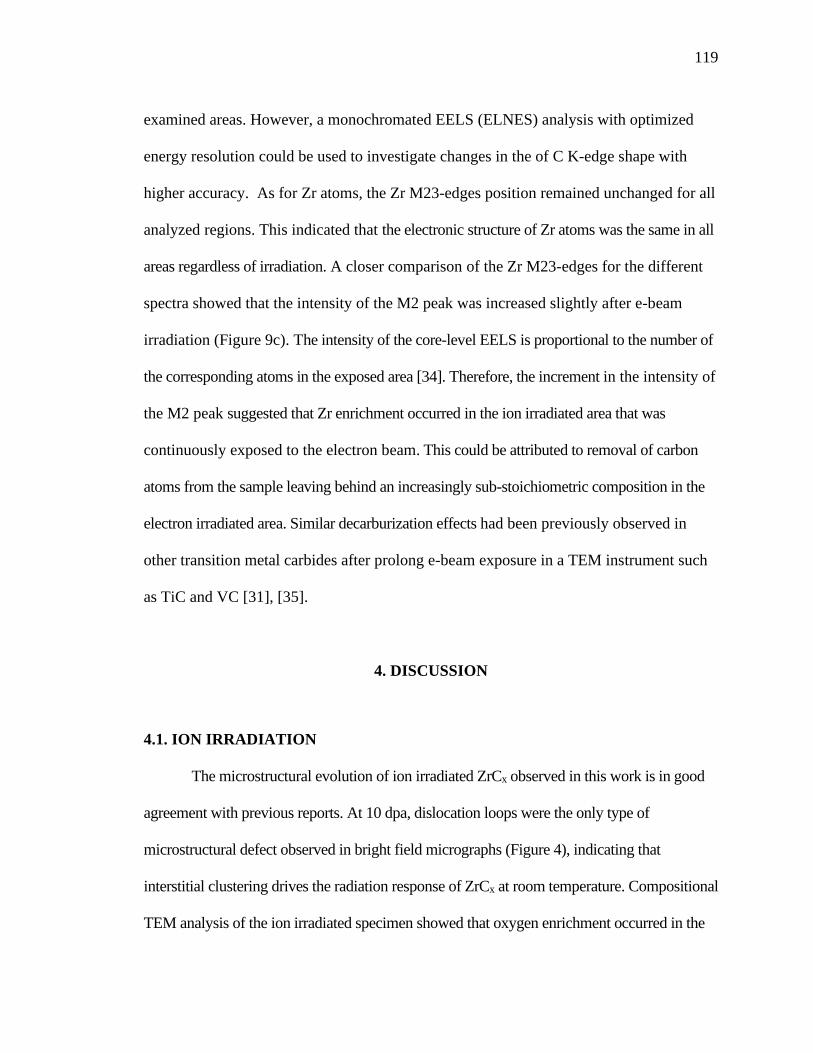
119
examined areas. However, a monochromated EELS (ELNES) analysis with optimized
energy resolution could be used to investigate changes in the of C K-edge shape with
higher accuracy. As for Zr atoms, the Zr M23-edges position remained unchanged for all
analyzed regions. This indicated that the electronic structure of Zr atoms was the same in all
areas regardless of irradiation. A closer comparison of the Zr M23-edges for the different
spectra showed that the intensity of the M2 peak was increased slightly after e-beam
irradiation (Figure 9c). The intensity of the core-level EELS is proportional to the number of
the corresponding atoms in the exposed area [34]. Therefore, the increment in the intensity of
the M2 peak suggested that Zr enrichment occurred in the ion irradiated area that was
continuously exposed to the electron beam. This could be attributed to removal of carbon
atoms from the sample leaving behind an increasingly sub-stoichiometric composition in the
electron irradiated area. Similar decarburization effects had been previously observed in
other transition metal carbides after prolong e-beam exposure in a TEM instrument such
as TiC and VC [31], [35].
4. DISCUSSION
4.1. ION IRRADIATION
The microstructural evolution of ion irradiated ZrCx observed in this work is in good
agreement with previous reports. At 10 dpa, dislocation loops were the only type of
microstructural defect observed in bright field micrographs (Figure 4), indicating that
interstitial clustering drives the radiation response of ZrCx at room temperature. Compositional
TEM analysis of the ion irradiated specimen showed that oxygen enrichment occurred in the

120
ion implanted layer. This is consistent with previous studies that have found evidence of
oxygen enrichment in the near surface of ion implanted ZrCx [36]. Despite the local
increase in oxygen content, no new oxide phases were formed during ion implantation. At
room temperature, the oxygen activity in the vacuum environment in which irradiation was
conducted is likely too low for oxidation, but high enough to allow dissolution of oxygen
atoms into the defective microstructure. The dissolved oxygen atoms presumably occupy to
carbon vacancies that were either generated during ion irradiation or present in the as-prepared
ceramic.
4.2. ELECTRON IRRADIATION
The results presented in Figure 5 indicated that t-ZrO2 nanocrystals formed during
electron beam exposure of the ion-irradiated ZrC foil. Interestingly, the oxide nanoprecipitates
only formed in pre-damaged areas of the TEM lamella that were continuously exposed to the
electron beam. This behavior suggests that both the electron beam and the microstructure of
the ZrCx matrix play a role in the formation of the oxide precipitates. To explain the
microstructural changes observed in this work, it is necessary to consider the effects of
electron-specimen interactions that may drive the oxidation process during electron
irradiation. These effects include radiolysis (ionization damage), electron beam heating, and
knock-on displacements. Due to the high electrical conductivity of ZrCx ceramics, radiolysis
damage is expected to be negligible during electron irradiation. Thus, only electron beam
heating and knock-on displacements effects are discussed below.
The inelastic scattering of electrons produces a local temperature increase in the
specimen during TEM observations [37]. This temperature rise can facilitate thermally-

121
activated processes such as diffusion and oxidation reactions. Given its high chemical
reactivity with oxygen, thermal oxidation of ZrCx can occur inside the TEM chamber, if
the temperature necessary for this process is reached in the microscope. Previous work on
thermal oxidation studies of ZrCx in low Po2 atmospheres has shown that oxidation
begins at ~300o C [17]. According to Fisher and Jencic’s model [38], the maximum
temperature rise ∆𝑇 associated with electron irradiation is given by:
∆𝑇 =𝐼
𝜋𝜅𝑒(
∆𝐸
𝑑) ln (
𝑏
𝑟𝑜) (2)
where 𝐼 is the beam current, 𝜅 is the thermal conductivity of the sample, 𝑒 is the electron
charge, 𝑟𝑜 is the effective radius of the heat sink, 𝑏 is the radius of the TEM sample, ∆𝐸
is the total energy loss by the electron in a sample of thickness 𝑑. Electron energy loss of
ZrC is 1.5 ev/nm at 300 keV, which is negligible compared to the initial energy of the
incident electrons. As a result, ∆𝐸
𝑑 is assumed to be constant and given by the stopping
power of the incident electrons 𝑑𝐸
𝑑𝑥. In this study, electron irradiations were conducted in
both ion-irradiated and pristine ZrCx grains that had very different microstructures
(Figure 4 and 8). Since the thermal properties depend on microstructure, different values
of thermal conductivity are expected for the ion-irradiated and pristine areas of the ZrCx
foil. To calculate the e-beam heating effect for the pristine region, a thermal conductivity
value of 𝜅𝑎𝑣 = 26 𝑊
𝑚𝐾 was used. This value corresponded to average of the thermal
conductivity values reported in the literature for near stoichiometric ZrC [39] [40]. Based
on this assumption, the maximum temperature increase in the pristine area was estimated
to be less than 1 𝐾 under the e-beam irradiation conditions used in this work (𝐼 = 6 𝑛𝐴,
𝑏 = 1.5 𝑚𝑚, 𝑟𝑜 = 100 𝑛𝑚, and 𝑑𝐸
𝑑𝑥= 1.055
𝑒𝑉
𝑛𝑚). On the other hand, a significant

122
reduction in the thermal conductivity of ZrCx is expected for the ion-implanted area
because of the high density of dislocation loops and carbon vacancies present in this
region (Figure 3 and 4). Previous studies have reported a reduction of more than 60% in
the thermal conductivity for ion irradiated ZrCx [41],[42]. If a similar level of thermal
degradation were assumed in this work, then the maximum temperature rise in the ion
implanted regions would be ~3 𝐾. Consequently, it was concluded that the temperature
increment induced by e-beam irradiation is insufficient to produce thermal oxidation of
ZrCx under irradiation with 300 keV electrons.
Alternatively, knock-on atomic displacements can also occur during TEM
examination with energetic electrons [37]. In this case, atoms might be permanently
displaced from their normal lattice positions, if the energy that they receive through
elastic collisions surpasses their threshold displacement energy 𝐸𝑑. According to the
elastic collision model, the maximum energy transferred from the electron beam to the
target atoms by elastic collisions is given by:
𝐸𝑚𝑎𝑥 =2𝐸(𝐸+2𝑚𝑐2)
𝑀𝑐2 (3)
where 𝐸 is the energy of the incident electron, 𝑚 is the mass of the electron, 𝑀 is the
mass of the atom, and 𝑐 is the speed of light. Figure 10a) shows the calculated 𝐸𝑚𝑎𝑥 for
Zr, C and O atoms over a range of incident electron energies up to 400 keV. Oxygen
atoms were included in the displacement calculations because EDX and EELS analyses
indicated the presence of oxygen in the ion implanted layer (Figure S1). The horizontal
lines 1 and 2 in Figure 10a correspond to the average displacement energy 𝐸𝑑 for the C
and Zr sublattice in ZrC determined by ab-initio methods [24]. The incident electron
beam used in this work had an energy of 300 keV, which could transfer a maximum

123
energy of 9 eV to Zr atoms and 71 eV to C atoms. Since the threshold displacement
energy for Zr atoms is much higher than that received under irradiation with 300 keV
electrons, the direct displacement of Zr atoms should not occur in ZrC during TEM
examination. On the other hand, the threshold displacement energy for carbon atoms is
lower than that transferred by elastic collision with 300 keV electrons. Hence, direct
knock-on displacement of carbon atoms is likely to happen when a ZrC foil is analyzed
with a 300 keV e-beam.
Concerning the oxygen atoms, no experimental or theoretical values of 𝐸𝑑 for
oxygen in zirconium oxycarbides (ZrCxOy) were found in the literature. However, as a
reference value, the threshold displacement energy for oxygen in most oxides falls at
values around 40 eV [43]. In contrast to most oxides, vacancy-enhanced displacement
occurs in transition metal carbides due to the presence of carbon vacancies. This mechanism
significantly reduces the threshold displacement energy of carbon atoms because they can
be transferred directly into neighboring vacant sites. Since oxygen atoms also occupy
carbon vacancy sites, it is reasonable to assume that 𝐸𝑑 for oxygen in zirconium
oxycarbides is lower than in oxides (< 40 eV). Thus, oxygen atoms can be also displaced
by elastic collision with 300 keV electrons.
The most energetic displaced carbon and oxygen atoms can, in turn, transfer
energy to zirconium atoms through cascade collisions. In this case, the maximum energy
transfer to zirconium atoms by primary carbon and oxygen recoils is given by:
𝐸𝑚𝑎𝑥𝑍𝑟 =
4𝑀𝑍𝑟𝑀𝑥
(𝑀𝑍𝑟+𝑀𝑥)2 𝐸𝑚𝑎𝑥𝑥 (4)
where 𝑀𝑍𝑟 is the mass of the zirconium atom, 𝑀𝑥 is the mass of carbon or oxygen atoms,
and 𝐸𝑚𝑎𝑥𝑥 is the maximum energy of carbon and oxygen atoms as calculated from Eqn.

124
(3). Figure 10b presents the maximum recoil energies for Zr atoms after secondary
collisions with primary displaced carbon and oxygen atoms. Based on these results, 300
keV electrons cannot displace Zr atoms through secondary collisions with primary carbon
and oxygen recoils. Thus, the energy received by zirconium atoms from the incident
electron beam will increase the temperature of the specimen, leaving the Zr sublattice
undisturbed.
The carbon and oxygen atoms that are displaced by the energetic electrons can
diffuse throughout the TEM specimen due to radiation-enhanced diffusion (RED) effects.
According to the RED theory, the diffusion of atoms is directly related to the
concentration of microstructural defects [44]. Therefore, it can be expected that the RED
effects will be enhanced in the ion implanted region of the ZrC foil, where a higher
concentration of vacancies and dislocations exists (Figure 3 and 4). This difference in
diffusion properties could explain why microstructural changes were observed only in the
ion implanted region of the TEM lamella during electron irradiation (Figure 5), and not in
the pristine areas (Figure 8). Because the TEM foil is essentially two-dimensional, the
displaced atoms can only diffuse and accumulate on the surface of the specimen. As a
result, oxygen and carbon enrichment might occur in regions near the foil’s surface as the
electron irradiation proceeds. Eventually, if the local oxygen concentration exceeds the
solubility limit in the matrix, radiation-induced precipitation occurs.
The e-beam induced precipitation of ZrO2 nanocrystals could also be influenced
by the level of oxygen in the electron irradiated area. In this study, a higher oxygen
content was detected in the ion implanted regions of the TEM foil compared to the
pristine areas (Figure S2). This implies that more oxygen atoms could be displaced and

125
diffuse towards the foil surface during e-beam irradiation of the ion-implanted areas.
With more oxygen atoms reaching the foil surface, it is more likely that the oxygen
solubility limit will be surpassed, and oxide will form after e-beam illumination for a
certain period of time.
During electron irradiation of the ion-implanted areas in the TEM foil, it was noted
that the oxide diffraction rings appeared diffuse at the beginning and became sharper as
the electron irradiation continued (Figure 5). This behavior suggests that the nucleation of
the oxide precipitates is probably assisted by electron induced crystallization. Radiation-
induced-crystallization (RIC) has been previously observed in amorphous ZrO2 [45],
[46]. The transition from amorphous domains to crystalline ZrO2 is likely promoted by
the atomic rearrangements induced by knock-on collisions and other electronic
excitations during e-beam irradiation. However, the details of this transition will be
studied in future work. The indexing of the diffraction rings also indicated that the oxide
precipitates were t-ZrO2. Previous work has shown that tetragonal zirconia is
energetically favorable as the grain size decreases below a critical value of 15 nm [47].
Interestingly, evidence of decarburization in the electron irradiated area was also
observed after prolonged exposure to the e- beam (> 60 min). A similar phenomenon was
reported in electron irradiated TiC by Das et al. [31]. Decarburization of transition metal
carbides can lead to the formation of ordered superstructures, which produce extra
diffraction spots in the SAED patterns. In this study, no extra diffraction spots were
observed during electron irradiation of the ion-implanted areas. This indicates that
carbon ordering did not take place during electron irradiation at room temperature, likely
due to the high density of microstructural defects present in ion-implanted areas. Lastly,

126
it is also worth noting that the formation of oxide precipitates occurred before the
decarburization of the foil. This suggests that the oxygen atoms diffuse faster towards the
surface of the foil than the carbon atoms. A possible explanation for this behavior can be
attributed to the presence of dislocations in the ion implanted area, which can provide fast
pathways for the diffusion of oxygen atoms. Furthermore, the dislocation loops and
carbon vacancies can also serve as a sink for the displaced carbon atoms and prevent their
transport towards the surface. This process might be assisted by electron Ionizing effects
that promote redistribution of atoms in different types of traps (defects, grain boundaries,
etc.) in ceramics materials.
5. CONCLUSIONS
Sequential ion-electron irradiations of ZrCx were conducted with 10 MeV Au3+ ions
and 300 keV electrons to investigate the effects of defects produced during ion irradiation
on the response of ZrCx to successive electron irradiation. After ion irradiation of bulk
ZrCx, TEM observations revealed that dislocations loops were formed in the ion
implanted layer. Additionally, Raman analysis showed an increase in the number of
carbon vacancies following ion irradiation. Subsequent electron irradiation of the pre-
implanted ZrCx foil resulted in the formation of nanosized tetragonal ZrO2 precipitates
(5-10 nm) on the surface of the TEM lamella. The discretization of the oxide diffraction
rings suggested that the nanoprecipitates were formed by homogeneous nucleation and
were randomly oriented with respect to the ZrC matrix. The mechanism leading to the
formation of ZrO2 precipitates was elucidated based on analysis of the electron-specimen

127
interactions. It is proposed that ZrO2 precipitates formed through a knock-on
displacement of the oxygen atoms present in the ion implanted layer. The displaced
atoms were subsequently transported towards the surface of the TEM foil, likely assisted
by radiation-enhanced diffusion effects and momentum transfer during e-beam
irradiation, where oxide precipitation occurs. The results highlight the electron beam
sensitivity of ion implanted ZrCx and indicate that high-energy electron irradiation of pre-
damaged ZrCx foils can induce further modification in the microstructure and chemical
composition of the specimen. The outcomes of this work increase the understanding of the
microstructural response of ZrCx ceramics to different types of radiation provide new insight
into the inadvertent effects of the electron beam during TEM analysis of in-situ and ex-situ
ion irradiated ZrCx.
ACKNOWLEDGEMENTS
This research was supported by Nuclear Regulatory Commission Faculty
Development Grant NRC-HQ-84-15-G-0044 and by the Ceramics program of the U.S.
National Science Foundation as part of project DMR 1742086. The microscopy work was
conducted at the Electron Microscopy Center (EMC) of the University of Missouri
Columbia with partial funding through the EMC Excellence Microscopy Award.
Material synthesis and X-ray diffraction measurements were performed using facilities of
the Materials Research Center (MRC) located at the Missouri University of Science and
Technology. Ion irradiations were performed at the Ion Beam Materials Laboratory
located at the University of Tennessee, Knoxville.

128
Figure 1. Depth profile of damage level using SRIM Kinchin and Pease calculations, and
Au concentration as a function of depth for a fluence of 3.59×1015 cm-2
Figure 2. GIXRD diffraction patterns obtained from ZrC a) before, and b) after ion
irradiation at room temperature.

129
Figure 3. Raman spectra for the pristine and ion irradiated specimens.
Figure 4. (a) Bright field overview of the ion irradiated ZrC along [110] zone axis, and
(b) magnified bright field image showing dislocation loops in the ion implanted layer.

130
Figure 5. SAD pattern from ion irradiated ZrC (a) initially, (b) after 30 min, and (c) after
60 min of electron irradiation; (d) dark field imageafter 60 min of electron beam exposure
showing some bright ZrO2 precipitates (indicated by arrows).
Figure 6. (a) HR-TEM image and ( b) FFT pattern of the ion irradiated area after 60 min
of electron beam exposure; (c) Experimental FFT of precipitate (red box) and simulated
electron diffraction pattern based on the tetragonal structure of ZrO2.

131
Figure 7. (a) SAD pattern from the ion irradiated ZrC area after 100 min of electron beam
exposure, (b) overview dark field image showing the precipitates formed after electron
irradiation; (c) SAD pattern acquired in the ion irradiated area adjacent to the e-beam
irradiated region.
Figure 8. (a) Bright field micrograph of the pristine ZrC grain showing minor FIB
damage; (b) EELS spectra of pristine ZrC grain after e-beam exposure; SAD pattern from
pristine (c) initially, (d) after 30 min, and (e) after 60 min of electron irradiation.

132
Figure 9. EELS spectrum from ZrC grains obtained (a) from the pristine area, (b) ion-
irradiated area, and (c) ion-implanted area after 100 min of electron beam exposure.
Figure 10. (a) Maximum energy transfer to atoms by electrons, (b) maximum energy
transfer to Zr atoms by primary carbon and oxygen recoils.

133
Figure S1. Elemental mapping of the ion implanted area obtained by STEM-EDX after
ion irradiation with 10 MeV Au3+ to 10 dpa.
Figure S2. EELS spectrum from ion irradiated ZrC grain after electron beam exposure.
134
REFERENCES
[1] R. W. Harrison and W. E. Lee, “Processing and properties of ZrC, ZrN and ZrCN
ceramics: a review,” Adv. Appl. Ceram., vol. 115, no. 5, pp. 294–307, 2016.
[2] L. N. Grossman, “High-Temperature Thermophysical Properties of Zirconium
Carbide,” J. Am. Ceram. Soc., vol. 48, no. 5, pp. 236–242, 1965.
[3] K. Fukuda, K. Ikawa, and K. Iwamoto, “Fission product diffusion in ZrC coated
fuel particles,” J. Nucl. Mater., vol. 87, no. 2-3, pp. 367–374, 1979.
[4] Y. Katoh, G. Vasudevamurthy, T. Nozawa, and L. L. Snead, “Properties of
zirconium carbide for nuclear fuel applications,” J. Nucl. Mater., vol. 441, no. 1–3,
pp. 718–742, 2013.
[5] R. Ding, H. Wang, Y. Jiang, R. Liu, K. Jing, M. Sun, R. Zhang, S. Qiu, Z. Xie, H.
Deng, X. Wang, M. Kong, W. Jiang, W. Fang, and C. Liu, “Effects of ZrC
addition on the microstructure and mechanical properties of Fe-Cr-Al alloys
fabricated by spark plasma sintering,” J. Alloys Compd., vol. 805, pp. 1025–1033,
2019.
[6] G. Vasudevamurthy, T. W. Knight, E. Roberts, and T. M. Adams, “Laboratory
production of zirconium carbide compacts for use in inert matrix fuels,” J. Nucl.
Mater., vol. 374, no. 1-2, pp. 241–247, 2008.
[7] R. Liu, Z. M. Xie, J. F. Yang, T. Zhang, T. Hao, X. P. Wang, Q. F. Fang, and C. S.
Liu, “Recent progress on the R&D of W-ZrC alloys for plasma facing components
in fusion devices,” Nucl. Mater. Energy, vol. 16, no. May, pp. 191–206, 2018.
[8] C. J. Ulmer, A. T. Motta, and M. A. Kirk, “In situ ion irradiation of zirconium
carbide,” J. Nucl. Mater., vol. 466, pp. 606–614, 2015.
[9] D. Gosset, M. Dollé, D. Simeone, G. Baldinozzi, and L. Thomé, “Structural
evolution of zirconium carbide under ion irradiation,” J. Nucl. Mater., vol. 373, no.
1–3, pp. 123–129, 2008.
[10] D. Gosset, M. Dollé, D. Simeone, G. Baldinozzi, and L. Thomé, “Structural
behaviour of nearly stoichiometric ZrC under ion irradiation,” Nucl. Instruments
Methods Phys. Res. Sect. B Beam Interact. with Mater. Atoms, vol. 266, no. 12–13,
pp. 2801-2805, 2008.
[11] S. Pellegrino, J. P. Crocombette, A. Debelle, T. Jourdan, P. Trocellier, and L.
Thomé, “Multi-scale simulation of the experimental response of ion-irradiated
zirconium carbide: Role of interstitial clustering,” Acta Mater., vol. 102, pp. 79–
87, 2016.

135
[12] S. Agarwal, A. Bhattacharya, P. Trocellier, and S. J. Zinkle, “Helium induced
microstructure damage, nano-scale grain formation and helium retention behaviour
of ZrC,” Acta Mater., vol. 163, pp. 14–27, Jan. 2019.
[13] Y. Yang, W.-Y. Lo, C. Dickerson, and T. R. Allen, “Stoichiometry effect on the
irradiation response in the microstructure of zirconium carbides,” J. Nucl. Mater.,
vol. 454, no. 1–3, pp. 130–135, 2014.
[14] L. L. Snead, Y. Katoh, and S. Kondo, “Effects of fast neutron irradiation on
zirconium carbide,” J. Nucl. Mater., vol. 399, no. 2–3, pp. 200–207, 2010.
[15] J. Gan, M. Meyer, R. Birtcher, and T. Allen, “Microstructure Evolution in ZrC
Irradiated with Kr ions,” J. ASTM Int., vol. 3, no. 4, p. 12376, 2006.
[16] C. J. Ulmer, A. T. Motta, and M. A. Kirk, “In situ ion irradiation of zirconium
carbide,” J. Nucl. Mater., vol. 466, pp. 606–614, 2015.
[17] S. Shimada and T. Ishil, “Oxidation Kinetics of Zirconium Carbide at Relatively
Low Temperatures,” J. Am. Ceram. Soc., vol. 73, no. 10, pp. 2804–2808, 1990.
[18] B. S. Vasile, D. Craciun, P. Ionescu, D. Pantelica, G. Dorcioman, and V. Craciun,
“Microstructure of 800 keV Ar ion irradiated thin ZrC films,” Appl. Surf. Sci., vol.
442, pp. 773–777, 2018.
[19] J. Gan, Y. Yang, C. Dickson, and T. Allen, “Proton irradiation study of GFR
candidate ceramics,” J. Nucl. Mater., vol. 389, no. 2, pp. 371-325, 2009.
[20] Y. Zhang, M.L. Crespillo, H. Xue, K. Jin, C.H. Chen, C.L. Fontana, J.T. Graham,
and W.J. Weber, “New ion beam materials laboratory for materials modification
and irradiation effects research,” Nucl. Instruments Methods Phys. Res. Sect. B
Beam Interact. with Mater. Atoms, vol. 338, pp. 19-30, 2014.
[21] M. L. Crespillo, J. T. Graham, Y. Zhang, and W. J. Weber, “In-situ luminescence
monitoring of ion-induced damage evolution in SiO2 and Al2O3,” J. Lumin., vol.
172, pp. 208-218, 2016.
[22] M. L. Crespillo, J. T. Graham, Y. Zhang, and W. J. Weber, “Temperature
measurements during high flux ion beam irradiations,” Rev. Sci. Instrum., vol. 87,
no. 2, p. 024902, 2016.
[23] J. F. Ziegler, M. D. Ziegler, and J. P. Biersack, “SRIM - The stopping and range of
ions in matter (2010),” Nucl. Instruments Methods Phys. Res. Sect. B Beam
Interact. with Mater. Atoms, vol. 268, no. 11-12, pp. 1818-1823, 2010.
[24] M. J. Zheng, I. Szlufarska, and D. Morgan, “Ab initio prediction of threshold
displacement energies in ZrC,” J. Nucl. Mater., vol. 471, pp. 214–219, 2016.
136
[25] R. E. Stoller, M. B. Toloczko, G. S. Was, A. G. Certain, S. Dwaraknath, and F. A.
Garner, “On the use of SRIM for computing radiation damage exposure,” Nucl.
Instruments Methods Phys. Res. Sect. B Beam Interact. with Mater. Atoms, vol.
310, pp. 75–80, 2013.
[26] Y. Zhang, M. A. Tunes, Matheus, M.L. Crespillo, F. Zhang, W. L. Boldman, P. D.
Rack, L. Jiang, C. Xu, G. Greaves, S. E. Donnelly, L. Wang, and W. J. Weber,
“Thermal stability and irradiation response of nanocrystalline CoCrCuFeNi high-
entropy alloy,” Nanotechnology, vol. 30, no. 29, p. 294004, 2019.
[27] G. S. Was, Fundamentals of radiation materials science: Metals and alloys,
second edition. 2016.
[28] ASTM, “ASTM C373-14 Standard Test Method for Water Absorption, Bulk
Density, Apparent Porosity, and Apparent Specific Gravity of Fired Whiteware
Products,” Astm C373-88, 1999.
[29] H. Wipf, M. V. Klein, and W. S. Williams, “Vacancy-Induced and Two-Phonon
Raman Scattering in ZrCx, NbCx, HfCx, and TaCx,” Phys. status solidi, vol. 108,
no. 2, pp. 489–500, 1981.
[30] S. Pellegrino, P. Trocellier, L. Thomé, S. Miro, J. M. Costantini, and E. Jouanny,
“Raman investigation of ion irradiated TiC and ZrC,” Nucl. Instruments Methods
Phys. Res. Sect. B Beam Interact. with Mater. Atoms, vol. 454, no. 1, pp. 61-67,
2019.
[31] G. Das, D. K. Chatterjee, and H. A. Lipsitt, “Electron irradiation damage in TiC,”
J. Mater. Sci., vol. 16, no. 12, pp. 3283–3291, 1981.
[32] V. Jeanne-Rose, V. Golabkan, J. L. Mansot, L. Largitte, T. Cesaire, and A.
Ouensanga, “An EELS-based study of the effects of pyrolysis on natural
carbonaceous materials used for activated charcoal preparation,” J. Microsc., vol.
210, no. 1, pp. 53–59, 2003.
[33] A. J. Craven and L. A. J. Garvie, “Electron Energy Loss Near Edge Structure
(ELNES) on the Carbon K-Edge in Transition Metal Carbides with the Rock Salt
Structure,” Microsc. Microanal. Microstruct., vol. 6, no. 1, pp. 89–98, 1995.
[34] K. A. Mkhoyan and J. Silcox, “Electron-beam-induced damage in wurtzite InN,”
Appl. Phys. Lett., vol. 82, no. 6, pp. 859-861, 2003.
[35] A. J. Craven, M. M. Cluckie, S. P. Duckworth, and T. N. Baker, “Analysis of
small vanadium carbide precipitates using Electron Energy Loss Spectroscopy,”
Ultramicroscopy, vol. 28, no. 1-4, pp. 330-334, 1989.

137
[36] Y. Pipon, N. Toulhoat, N. Moncoffre, G. Gutierrez, A. Maître, and M. Gendre,
“Influence of the Oxygen content on the thermal migration of Xenon in ZrCxO1−x,”
J. Nucl. Mater., vol. 440, no. 1–3, pp. 546–552, 2013.
[37] D. B. Williams and C. B. Carter, Transmission Electron Microscopy. Boston, MA:
Springer US, 2009.
[38] I. Jenc̆ic̆, M. W. Bench, I. M. Robertson, and M. A. Kirk, “Electron‐beam‐induced
crystallization of isolated amorphous regions in Si, Ge, GaP, and GaAs,” J. Appl.
Phys., vol. 78, no. 2, pp. 974–982, 1995.
[39] W. Lengauer, S. Binder, K. Aigner, P. Ettmayer, A. Guillou, G. Debuigne, and G.
Groboth, “Solid state properties of group IVb carbonitrides,” J. Alloys Compd.,
vol. 217, no. 1, pp. 137–147, 1995.
[40] R. E. Taylor and E. K. Storms, “Thermal Transport in Refractory Crabides,” 1976.
[41] C. Jensen, M. Chirtoc, N. Horny, J. S. Antoniow, H. Pron, and H. Ban, “Thermal
conductivity profile determination in proton-irradiated ZrC by spatial and
frequency scanning thermal wave methods,” J. Appl. Phys., vol. 114, no. 13, p.
133509, 2013.
[42] C. Jensen, M. Chirtoc, J. S. Antoniow, and H. Ban, “In-depth thermal-conductivity
profile of ion-irradiated zirconium carbide using scanning thermal microscopy,”
Int. J. Thermophys., vol. 34, no. 4, pp. 597–608, 2013.
[43] S. J. Zinkle and C. Kinoshita, “Defect production in ceramics,” J. Nucl. Mater.,
vol. 251, no. 11, pp. 200-217, 1997.
[44] G. J. Dienes and A. C. Damask, “Radiation Enhanced Diffusion in Solids,” J.
Appl. Phys., vol. 29, no. 12, pp. 1713–1721, 1958.
[45] A. G. Bagmut and V. M. Beresnev, “Kinetics of the electron beam induced
crystallization of amorphous ZrO2 films obtained via ion-plasma and laser
sputtering,” Phys. Solid State, vol. 59, no. 1, pp. 151–155, 2017.
[46] H. M. Naguib and R. Kelly, “The crystallization of amorphous ZrO2 by thermal
heating and by ion bombardment,” J. Nucl. Mater., vol. 35, no. 3, pp. 293-305,
1970.
[47] R. C. Garvie, “Stabilization of the tetragonal structure in zirconia microcrystals,”
J. Phys. Chem., vol. 82, no. 2, pp. 218–224, 1978.

138
SECTION
3. SUMMARY AND CONCLUSIONS
The purpose of this dissertation was to investigate the microstructural evolution of
ZrCx ceramics under ion and electron irradiation conditions. In the first part of the thesis,
efforts were made to characterize the microstructure of ZrCx irradiated with 10 MeV
Au3+ ions up to doses of 30 displacement per atoms (dpa) at 800 oC. To date, most of the
studies on irradiated ZrCx have only focused on the low dose (< 5 dpa), low temperature
(25 ºC) irradiation regime. Thus, the results of the first part of the dissertation contribute
to extend the current state of knowledge of the irradiation response of ZrCx at conditions
that are relevant to the operation of advanced Gen-IV gas-cooled nuclear reactors.
Post-irradiation examination (PIE) of the ion-irradiated specimens was conducted
using a complementary set of techniques (transmission electron microscopy, X-ray
diffraction, and Raman spectroscopy) to provide a more comprehensive view of the
irradiation response of ZrCx ceramics. The results indicated that ZrCx did not amorphize
at doses up to 30 dpa, confirming its superior radiation stability. Coarsening of the
defective microstructure, as a function of dose, was revealed by transmission electron
microscopy analysis. Black dot defects were observed at low doses (0.5 dpa), and tangled
dislocation networks were formed at 5 dpa. Beyond this dose, little change was observed
in the irradiated microstructure, which suggested that a balance had been reached
between irradiation damage buildup and dynamic annealing of defects. Diffraction
analysis showed a change in the defect structure occurred at doses close to ~2.5 dpa. This

139
change was attributed to coalescence of dislocation loops and formation of dislocation
networks. The evolution of lattice parameter with dose indicated that uptake of
adventitious oxygen could occur in specimens irradiated at high doses. Oxygen uptake
might be assisted by radiation-enhanced diffusion processes by the changing
microstructure (i.e. pipe diffusion at high doses). Raman spectroscopy analysis indicated
an increase in non-stochiometry after irradiaton, due to an increase in carbon vacancies
produced by the irradiation.
Additionally, concurrent oxidation of ZrCx occured during ion irradiation at
800 oC. Nanosized, discrete ZrO2 nodules were observed to grow over the surface of
ZrCx. No amorphization of the ZrO2 precipitates was observed at doses up to 15 dpa,
confirming the high radiation resistance of ZrO2 phase. Concomitant reduction in size
and surface coverage of the oxide nodules was observed at high doses, indicating that
radiation-induced processes could enhance the dissolution of oxide precipitates under
irradiation conditions. Morphological changes were also observed in the irradiated oxide
nodules as a function dose. At doses above 2.5 dpa, the oxide islands became more
faceted and exhibited diffuse oxide/matrix interfaces. Furthermore, nucleation and
growth of cavities was observed within the oxide nodules irradiated to 2.5 dpa and above.
These results shed light on the complex in-service oxidation of ZrCx in high temperature
nuclear reactors and provide information that will enable better design and safe operation
of the next generation of nuclear power systems.
In the second part of the dissertation, the microstructural evolution of ZrCx under
sequential ion-electron irradiation conditions was investigated. First, bulk ion irradiation
of ZrCx was conducted with 10 MeV Au3+ ions at room temperature. TEM analysis of the

140
ion-irradiated specimen revealed that dislocations loops were formed in the ion implanted
layer. Additionally, Raman analysis showed an increase in the number of carbon
vacancies following ion irradiation. Subsequent electron irradiation of the pre-implanted
ZrCx foil in the TEM instrument resulted in the formation of nanosized tetragonal ZrO2
precipitates (5-10 nm diameter) on the surface of the lamella. The discretization of the
oxide diffraction rings in the SAED patterns suggested that the nanoprecipitates were
formed by homogeneous nucleation and were randomly oriented with respect to the ZrCx
matrix. The mechanism leading to the formation of ZrO2 precipitates was elucidated based
on analysis of the electron-specimen interactions. It is proposed that ZrO2 precipitates
formed through a knock-on displacement of the oxygen atoms present in the ion
implanted layer. The displaced atoms are subsequently transported towards the surface of
the TEM foil, likely assisted by radiation-enhanced diffusion effects and momentum
transfer during e-beam irradiation, where oxide precipitation occurs.
Overall, the work presented in this dissertation led the authors to the following
conclusions:
1. Even though ZrCx ceramics exhibit high radiation resistance up to doses of 30 dpa
at 800 ºC, precautions must be taken to prevent its oxidation during reactor
operation. Given the high thermodynamic driving force for oxidation of ZrCx,
reactors components based on ZrCx will be oxidize when expose to impure helium
coolant. Thus, it would be necessary to develop composites with improved
oxidation resistance or suitable environmental barrier coatings that will be capable
of protecting the structural integrity of ZrCx under normal operation conditions of
Gen-IV gas-cooled reactors.

141
2. The results of the second part of the dissertation highlight the electron beam
sensitivity of ion implanted ZrCx. High-energy electron irradiation of pre-damaged
ZrCx foils can induce further modification in the microstructure and chemical
composition of the specimen. Therefore, precautions must be taken to prevent the
incorporation of inadvertent effects during TEM analysis of in-situ and ex-situ ion
irradiated ZrCx.

142
4. FUTURE WORK
Several suggestions are presented in this section for advancing understanding of
the radiation response of ZrCx ceramics:
1. It was discovered that oxygen uptake occurs during high temperature ion irradiation
of ZrCx. More research is needed to understand the mechanisms driving the oxygen
incorporation into the substrate. This effort will likely require the combination of
experiments and simulations. Understanding the mechanisms of oxygen-uptake
will be valuable for engineering optimal ion irradiation techniques that prevent
and/or alleviate oxygen uptake in sensitive materials such as ZrCx. Developing high
fidelity ion irradiations is essential to evaluate the response to irradiation of core
materials.
2. It has been shown that concurrent oxidation occurs during ion irradiation of ZrCx
at 800 ºC. It is recommended to conducting additional irradiation experiments at
various temperatures and doses to provide a better understanding of the oxidation
mechanism of ZrCx under irradiation conditions. Additionally, future analysis of
the oxidation islands should perform atomic force microscopy (AFM)
measurements to obtain a 3D reconstruction of the oxide islands. This will enable
evaluate the dimensions and faceting of the oxide nodules accurately. Such
parameters can be used as input/validation parameters in future simulations models
of ZrCx oxidation.
3. Raman analysis in transverse TEM lift-out specimens. In the current work, Raman
measurements were conducted on the surface of the ion-irradiated specimens. Since

143
the Raman penetration depth is strongly dependent on laser power and the
material’s optical density, it is difficult to know accurately if the Raman signal
originated from the near surface area, peak damage area, or non-irradiated area of
the ion-irradiated specimen. Therefore, to overcome this issue and obtain a more
accurate knowledge of the distribution of carbon vacancies along the implantation
profile, it is recommended to perform Raman analysis on transverse cross section
obtained by FIB lift-out.
4. The structure of the ion irradiated ZrCx was characterized by TEM analysis to a
limited extent. It is recommended to perform a detailed TEM analysis of the defect
population (e.g. dislocation type and nature) and change in chemical properties
(such as radiation induced segregation) as a function of dose. The knowledge of the
defect characteristics including loop nature, Burgers vectors, and habit or slip
planes, will constitute a significant step to better understand and predict the
behavior of ZrC under irradiation conditions.
5. It is also recommended to perform in-situ ion irradiation in thin foil ZrCx
specimens to investigate the mechanism of radiation-induced oxygen segregation.
144
APPENDIX
FABRICATION AND MICROSTRUCTURAL ANALYSIS OF HOT-PRESSED
ZrCX WITH LOW Hf-CONTENT
Raul Floreza Xiaoqing Heb,c, Tommi A. Whitec,d, Gregory Hilmase, William
Fahrenholtze, Joseph Grahama,e*
a. Nuclear Engineering Program, Missouri University of Science and Technology,
65409 Rolla, MO, United States
b. Electron Microscopy Core, University of Missouri, 65211 Columbia, MO, United
States
c. Department of Mechanical and Aerospace Engineering, University of Missouri, 65211
Columbia, MO, United States
d. Department of Biochemistry, University of Missouri, Columbia, MO, 65211, United
States
e. Department of Materials Science and Engineering, Missouri University of Science and
Technology, 65409 Rolla, MO, United States
ABSTRACT
Zirconium Carbide (ZrCx) powder with low Hf content (~400 ppm) was
synthesized by carbothermal reduction of ZrO2 with carbon black. The synthesized powder
was hot-pressed without any sintering additives at 2200 ºC to produce ZrCx ceramics with
relative density >95%. Microstructural analysis revealed ZrCx monoliths with a mean grain
size of 4.2 µm and residual carbon and oxycarbide inclusions. The formation of carbon and
oxygen-rich inclusions was attributed to the presence residual free carbon and oxide
contaminants in the starting ZrCx powder. Raman analysis evidenced structural

145
reorganization of free carbon into the disordered graphite inclusions during hot pressing.
Additionally, transmission electron microscopy analysis of the oxycarbide inclusions
showed a complex core-shell structure, which exhibited compositional differences between
the core and shell regions. The results of this work provide new insights into role of the
main impurities on the microstructural evolution of ZrCx ceramics during densification.
Keyworks: ZrCx, Hot Pressing, Microstructure, XRD, Raman, EBSD, TEM
* Corresponding author:
Email:[email protected]
1. INTRODUCTION
Zirconium Carbide (ZrCx) is a promising inert matrix fuel (IMF) matrix material
for advanced gas-cooled fast reactors (GFR) [1]. This type of Gen-IV nuclear reactor is
designed to operate at a nominal temperature of 1400 ºC and has the unique ability to
burn long-lived transuranic elements and fission products [2]. As a potential inert matrix
fuel for GFR, ZrCx exhibits several advantages over both oxide and metal matrix
alternatives. Foremost of these advantages include: high melting point (Tm=3420o C) [3],
outstanding mechanical properties [4], higher thermal and electrical conductivities than
SiC [5], resistance to fission product attack [6], low neutron absorption cross section [7],
and microstructural stability under irradiation conditions [8], [9], [10].
ZrCx is known for its poor sinterability due to its highly covalent bonding
character and low self-diffusion coefficients [11], [12], [13]. Consequently, high
temperatures (e.g., >2000°C) and pressure assisted methods are usually needed to

146
produce dense monolithic ZrCx ceramics with the required structural properties for
nuclear applications. Different sintering methods have been used to fabricate dense ZrCx
bodies including reactive and non-reactive hot-pressing [14], spark plasma sintering
(SPS) [15], pressureless sintering (PLS) [16] , and arc melting [17]. Among these
methods, SPS and hot-pressing of ZrCx powders produced by the carbothermal reduction
are the most suitable routes for large scale production. Examination of the microstructure
morphology, equilibrium phase behavior [18], thermomechanical properties [19],
[20],[21], fission product release [22], [23], and oxidation behavior [24], [25] of ZrCx
ceramics has been previously reported. Furthermore, several studies have been conducted
to understand the microstructural evolution of ZrCx ceramics under different types of
irradiation such as neutron [10], heavy ions [9], [26], [27] and protons [8], [28].
Certainly, the historic data on ZrCx have provided insightful into the behavior of ZrCx
that is pertinent to its use as inert matrix fuel in GFRs. However, a careful examination of
the literature shows that it lacked detailed structural and chemical compositional
assessment of the pre-irradiated ZrCx specimens, preventing a complete understanding of
irradiation behavior of ZrCx. Most of the previous work has been conducted on ZrC
ceramics produced from commercially available powders with quantitative analysis
rarely reported.
One of the main limitations of the previous work on ZrCx is the lack of detailed
chemical analysis for Hafnium (Hf) content. Hafnium is a ubiquitous substitutional
impurity in zirconium precursors that is difficult to separate because of its chemical
similarity to zirconium [29]. Application in GFRs have a stringent specification limit for
Hf content in inert fuel matrices due to its deleterious effects in the neutronic and thermal

147
properties of ZrCx ceramics. Hf has a high thermal neutron absorption cross-section and
resonance integral that affect the neutron economy in a nuclear reactor [30]. Moreover,
the presence of substitutional Hf impurities (HfZr) in ZrCx will degrade the phonon
contribution to the thermal conductivity due to the large mass difference between Hf and
Zr and resulting enhancement in phonon scattering [31], [32]. Microstructural changes
might also be induced by the presence of Hf impurities in ZrCx. In this regard, the
combination of Hf impurities in ZrCx and the temperatures typically used for synthesis
may either inhibit formation of other phases in the Zr-C system or result in relaxation to
disordered states that remain metastable when the system is cooled to room temperature.
Therefore, to provide a more fundamental understanding of the thermal and structural
properties of ZrCx before and after irradiation, it is essential to fabricate high purity ZrCx
ceramics with low Hf content and perform a comprehensive characterization of the
resulting microstructure.
The purpose of this study was to characterize the microstructure of hot-pressed ZrCx
ceramics with low Hf-content.
2. MATERIALS AND METHODS
2.1. SAMPLE PREPARATION
This section describes the preparation route of the powder and the densification
conditions used to fabricate the ZrC billets.
2.1.1 Synthesis of ZrO2 precursor. High purity ZrO2 powders with low Hf
content were synthesized by precipitation using ZrCl4 (Reactor grade, >99.5% metal

148
basis, Alfa Aesar) and NH4OH (28 %, Alfa Aesar) as starting materials. Precipitation
was induced by dropwise addition of 28% NH4OH to 0.4 M aqueous ZrCl4 solution until
the pH reached 10. After aging for 30 minutes under strong magnetic stirring, the
precipitate was filtered and washed with deionized water to remove chloride ions. The
hydrous cake was then dried at 120 oC overnight. Afterwards, the powder was calcined in
a convection oven at 700 oC for 4 hours to produce ZrO2. The obtained powder was
lightly ground with a mortar and pestle and passed through a 60 mesh sieve.
2.1.2. Synthesis of ZrC powder. The synthesized ZrO2 and carbon black (BP-
1100, Cabot Corporation, Alpharetta, GA, USA) powders were used as starting materials
for ZrC synthesis. The starting powders were batched with a molar ratio of ZrO2:C=1:3.
This composition was selected to produce a ZrC ceramics with a C/Zr=1 stoichiometry,
which is the target stoichiometry of the ZrC fuel development program in the United
States [10]. The powder mixture was ball-milled using zirconia milling media and
acetone for 24 hours. Afterwards, the slurry was dried by rotary evaporation (Rotavapor
R-124; Buchi, Flawil, Germany) at a temperature of 80 oC, under low vacuum (~27 kPa),
and at a rotation speed of 120 rpm. The dried powder was passed through a 50-mesh
sieve and pelletized by uniaxial pressing before carbothermal reduction.
Solid state carbothermal reduction was conducted in a graphite element furnace
(3060-FP20, Thermal Technology, Santa Rosa, CA, USA) under mild vacuum conditions
(~20 Pa). The mixed powder was heated from room temperature to 1800 oC at a heating
rate of 10 oC/min, and dwell time of 6 hours to promote the reaction:
𝑍𝑟𝑂2 + (2 + 𝑥 − 𝑦)𝐶 → 𝑍𝑟(𝐶𝑥, 𝑂𝑦) + (2 − 𝑦)𝐶𝑂 ↑ (1)

149
2.1.3. Densification. A pellet was prepared by hot-pressing the synthesized ZrC
powder. The powder was hot pressed in a 25.4 mm cylindrical graphite die lined with
BN-coated (SP-180 Cerac, Milwaukie, WI) graphite foil (2010-A; Mineral Seal Corp,
Tucson, Arizona). Before hot pressing, the powder was loaded into the die and cold
compacted in a uniaxial press at ~2MPa. The powder was then heated under vacuum (~20
Pa) to 1600 ºC with an average heating rate of 20 ºC/min. Upon reaching 1600 ºC, the
furnace was backfilled with helium and a uniaxial pressure of 32 MPa was applied to the
powder compact. The furnace was then heated at 50 ºC/min to 2200 0C. After 90 min, the
furnace was cooled at ~50 ºC/min. The load was removed when the die temperature
dropped below 1600 ºC.
Following densification, the specimens for microscopy analysis from the billet
parallel to the hot pressing with a slow-speed diamond saw. The surface of the ZrC foil
was then polished to a 0.25 μm mirror-finish using successively finer diamond abrasives.
After polishing, the specimens were ultrasonically cleaned in ethanol for 15 min at room
temperature.
2.2. MATERIAL CHARACTERIZATION
This section describes the experimental techniques that were used to examine the
microstructure of the as-fabricated specimens.
2.2.1. Density and Chemical Analysis. The bulk density of the hot-pressed billet
was measured by the Archimedes’ method performed in accordance with ASTM C73
using distilled water as the immersing medium [33]. The relative density was calculated
by dividing the Archimedes’ density by the estimated theoretical density of ZrC (𝜌=6.71

150
g/cm3). The Hf content in the as-fabricated billet was determined by instrumental neutron
activation analysis (NAA) performed at the Missouri University of Science and
Technology Reactor (MSTR). The details of the NAA experiment will be published in a
companion paper. Chemical analyses for carbon, oxygen and nitrogen content were
conducted by the direct combustion method using infrared absorption detection. Carbon
(CS600; Leco, St. Joseph, MI), oxygen and nitrogen (TC500; Leco, St. Joseph, MI)
contents were measured by grinding part of the dense specimen to ~200 mesh. Three
measurements were conducted for each element to establish repeatability.
2.2.2. X-Ray Diffraction. Phases analysis for the ZrO2 and ZrC powders was
performed using X-ray diffraction (XRD). The patterns were collected on a PANalytical
X’Pert3 Powder diffractometer (Malvern Panalytical Inc., Westborough, MA, USA)
fitted with Cu Kα radiation source (Åλ=1.5418Å). The powder pattern were acquired at
room temperature using a step size of 0.02626º with a counting time of 1 s over the 2θ
range 5-90º. Diffraction patterns were acquired over the 2θ range 25-90º. X-ray tube
operation conditions were 45 kV and 40 mA.
XRD analysis was also performed on polished cross section of the hot pressed billet
using a PANanlytical X’Pert Pro Multipurpose Diffractometer (MPD) fitted with a Cu X-
ray tube and an X’Celerator area detector. Diffraction patterns were acquired over the 2θ
range 5-90º with a step size of 0.03º and 0.5 s of exposure at each step. X-ray tube
operation conditions were 40 kV and 40 mA. XRD patterns were analyzed by the
Rietveld method (RIQAS, Materials Data, Inc., Livermore, CA, USA).
2.2.3. Raman Spectroscopy. Raman measurements were collected using a
HORIBA Jobin Yvon LabRAM ARAMIS microRaman spectrometer (Horiba, Edison,
151
NJ). The specimens were excited by a 632 nm He/Ne laser focused to a 2-3 µm spot
using a 50× microscope objective lens. Raman spectra were acquired in the
backscattering geometry. The laser power was below 2 mW to prevent local heating of
the sample. All measurements were conducted at room temperature.
2.2.4. Electron Microscopy. Microstructure of the as-fabricated pellet was
analyzed on polished cross sections by field emission scanning electron microscopy
(FIB-SEM SciosTM DualBeamTM, FEI, Hillsboro, Oregon). Key microstructural features
like content of secondary phases and residual porosity were evaluated from FESEM
micrographs acquired using an accelerating voltage of 5 keV. Electron backscattered
diffraction (EBSD), coupled with energy dispersive X-ray spectroscopy (EDS), was
performed using an Oxford HKL system and energy dispersive spectrometer in the FEI
Scios DualBeam scanning electron microscope. EBSD conditions utilized for the analysis
were a 20 kV accelerating voltage, 15 mm working distance and a 70° tilt. A 0.15 μm step
size was selected for the analysis. The specimen was analyzed using a single scan; with
an average area large enough to include more than 50 unique grains and thereby achieve
a larger statistical sample for determining grain size and grain boundary character [17].
The specimen for TEM analyses was prepared by the focused ion beam (FIB) lift-out
technique. A 15 μm (width) × 10 μm (depth) rectangular lamella was thinned to electron
transparency by the FIB (~50 nm). The TEM lamella was imaged using a FEI Tecnai
TF30-FEG Twin STEM (FEI, Hillsboro, OR, USA) working at 300 kV. Electron energy
loss spectroscopy (EELS) was used to characterize the local elemental composition.
High resolution transmission electron microscopy (HRTEM) was used to reveal
microstructural details of the inclusions.

152
3. RESULTS
From the XRD analysis of the synthetized ZrO2 powder (Fig. 1a), peaks for
monoclinic phase (JCPDS card 81-1314) and tetragonal phase (JPSD card 50-8019) were
identified. The peaks were broad, presumably due to the small crystallite size. Rietveld
analysis of the XRD data yielded tetragonal phase fractions of approximately 5 wt%. The
crystallite sizes estimated by Rietveld method were ~30 nm for both tetragonal and
monoclinic ZrO2 phases. Fig. 1b shows the XRD pattern for the ZrCx powder synthesized
using a starting ZrO2:C molar ra voltio 1:3 and heated to 1800 ºC. ZrCx, with Fm3̅m
crystal space group (JCPDF card 35-0784), was the only phase detected.
The as-sintered ZrCx pellet had a relative density of 95%. Gas fusion analysis
indicated that the as-fabricated ZrC pellet contained 11.53 wt% carbon, 1.01 wt% oxygen
and 0.204 wt % nitrogen. The oxygen and nitrogen impurities could come from the
starting powder used for carbothermal reduction or introduced during processing of the
billet. The hafnium content measured by NAA was about 400 parts per million (wppm).
Fig. 1c shows the XRD pattern obtained from the cross sectioned ZrCx pellet. The only
phase detected was ZrCx and no extra peaks were apparent. The empirical correlation
between lattice parameter and carbon content determined by Jackson and Lee [34] was
used to estimate the carbon content from the lattice parameter determined by Rietveld
refinement of the XRD pattern. The lattice parameter of the pellet determined by Rietveld
refinement was 4.689064 Å, corresponding to a carbon stoichiometry of ZrC0.92.
The microstructure of the as-sintered ZrC billet is depicted in Fig. 2. Individual
equiaxed ZrC grains were apparent in the micrograph due to channeling contrast. The

153
densified microstructure contained discrete porosity and secondary phases. These features
were discriminated based on their grey level intensity and morphological variances with
respect to each other and the ZrC matrix. The porosity appeared as round black inclusions
with charging around the edges. Small pores with diameters <1.5 µm were observed at
the grain boundaries and entrapped within the ZrC grains. No clustering of pores was
observed in the microstructure. The fraction of porosity calculated using computerized
image analysis was estimated to be less than 7 vol%; It should be mentioned, however,
that charging effects around the pores made accurate estimation of pore diameters
difficult. The measured fraction of porosity was in good agreement with the relative
densities determined by Archimedes’ method. In addition to porosity, traces of a
secondary phase were also identified in the as-sintered billet. This phase appeared black
in contrast with respect to ZrC grains and without charging, indicating that it is likely to
be carbon.
EBSD analysis was also conducted for phase identification and to determine grain
size distribution and grain boundary character. An inverse pole figure map from EBSD
measurements is shown in Fig. 4a. The collected Kikuchi maps were fit with
crystallographic information for ZrC, m-ZrO2, t-ZrO2, c-ZrO2, and C-graphite, which
could occur within the composition of interest. The EBSD analysis did not detect any
precipitates in the matrix, probably because of the large spot size used during the scan.
The white regions in the inverse pole figure map were points where the Kikuchi patterns
could not be indexed. They were most probably defects in the surface layer such as
residual porosity or precipitates that were extracted during ceramographic preparation.
According to the EBSD orientational map, the microstructure of the as-prepared ZrC

154
pellet was inhomogeneous and exhibited a multimodal grain size distribution (Fig 4b).
The average grain diameter was around 4.2 µm and an aspect ratio was 0.5. The
microstructure revealed large grains (10 μm) with porosity that was entrapped within the
grains. This is typical for ZrC sintered with no additives, which typically reach only 96–
98% of theoretical density due to rapid grain growth prior to complete densification
[35],[36].
Pole figure analysis (Fig. 4c) indicated that the microstructure of the as-sintered
pellet was not textured, in agreement with the XRD results. Additionally, the grain
boundary misorientation histogram (Fig 2d) showed that the pellet contained a large
fraction (>90%) of high angle grain boundaries (> 15o misorientation), which is
characteristic of polycrystalline materials. Analysis of the misorientation maps of the
grain boundaries also showed that the larger grains had relatively few boundaries with
low angle misorientation (Fig 5a). This suggested that the absorption of low angles grain
boundaries was the predominant mechanism activated during grain growth [37].
To gain further information about the spatial distribution and chemical
composition of the secondary phase, backscattered electron images and elemental
chemical maps were acquired (Fig. 3). The backscattered electron micrograph (Fig 2a)
showed dark inclusions randomly distributed within the lighter contrast ZrC matrix.
These dark inclusions appeared approximately uniform in size and shape. SEM/EDS
maps (Fig 3b-d) indicated the presence of carbon-enriched and oxygen-enriched
precipitates in the ZrC matrix.
Further analysis was done in the TEM to confirm EBSD findings and determine if
any additional phases were present in as-sintered pellet that were below the resolution of

155
the EBSD. An overview of the microstructure in the TEM lift-out is given in Fig. 6a. The
High Angle Annular Dark Field (HAADF) image of the specimen showed that local
heterogeneities existed at the nanoscale level within the ZrC matrix. Although most of
the grains appeared to be uniform in composition, some grains contained a few dark and
medium contrast inclusions with sizes ranging between 50 and 300 nm. These inclusions
were mainly inside the ZrCx grains, although some of them were also observed along the
grain boundaries. EELS point spectra were acquired at the inner and outer regions of one
of the inclusions (Fig. 6b, c, and d) to confirm its chemical composition. The results
indicated that the inner region was oxygen-rich compared to the outer region. Moreover,
detailed analysis of the EELS spectra revealed differences in the carbon K-edge between
inner and outer regions of the inclusion. The fine structure of carbon K-edge EELS
spectra acquired from the periphery of the inclusion (Figure 6b and c) was identical to
literature references for the C K-edge in ZrCx [38]. On the other hand, the carbon K-edge
obtained from the core of the inclusion (Fig. 6d) differed significantly from the C fine
structure of ZrCx. This suggested that either a partial zirconium oxycarbide phase formed
within the core area or, more likely, the core of the inclusion contained a mixture zirconia
and amorphous carbon.
To determine the phase of the inclusions, selected area electron diffraction
(SAED) analysis was performed. Fig. 7c shows a representative SAED pattern acquired
from one of the dark inclusions located inside a ZrCx grain (Fig 7a). Only one set of
diffraction spots was observed in the electron diffraction pattern from the area that
contained both matrix and inclusion. Indexing of the SAED pattern showed that the spots
were consistent with the ZrC phase along the [211] zone axis. This result suggested that

156
the inclusions had a very similar structure to the ZrC matrix. One possibility is that these
inclusions are simply ZrC with a higher dissolved oxygen content that is giving the
elemental contrast observed in the HAADF micrograph. Previous studies have indicated
that oxygen dissolution affects the lattice parameter of ZrCx [39]. However, the
difference in lattice parameter between the matrix and the inclusion might be so small
that it cannot be detected by SAED analysis.
The microstructure of the inclusions was also investigated in the HRTEM mode.
Fig. 8c shows a HRTEM image of the inclusion indicated in Fig. 8a. The micrograph
revealed that the inclusion had a complex core-shell structure. The core of the inclusion
contained a mixture of amorphous phase and nanosized crystals (<10 nm) as shown in
Fig. 8d. The fast Fourier transformation (FFT) pattern from the nanosized precipitates
present at the core of the inclusion was the same as the simulated pattern of tetragonal
ZrO2 phase in the 111 zone axis (Fig 8e and 8f). Therefore, there is conclusive evidence
that the core region of the inclusions contained oxide phase. The amorphous phase was
most likely carbon, which was detected by EELS analysis conducted at the core region
(Fig 8b). On the other hand, the shell region of the inclusion consisted of a crystalline
ZrC phase with a higher dissolved oxygen content than the ZrC matrix.
Raman spectroscopy was used to investigate the structure of the ZrC matrix and the
microscopic carbon inclusions that were visible in the fabricated pellet through optical
microscopy. The spectra acquired in ZrC grains (Fig 5a) showed Raman bands at
approximately 200, 275, 515 and 600 cm-1. These bands were assigned to defect related
modes induced by carbon vacancies in the ideal NaCl crystal structure of ZrC. The
spectrum obtained in this work was similar to those previously reported for

157
substochiometric ZrCx [40], [41], suggesting that carbon vacancies were present in the as-
sintered ZrC matrix. On the other hand, the Raman spectra for the carbon inclusions (Fig.
5b) were characterized by two first order prominent peaks: a Raman active 𝐸2𝑔 mode line
around 1590 cm-1 (known as G band), and the disorder induced peak at 1333 cm-1 (D band).
These peaks were due to sp2 and sp3carbon bonding respectively. The presence of both sp3
and sp2 hybridization is common for micron sized grains of graphite [42]. According to
previous studies [42], [43], the Raman intensity ratio (ID/IG) is related to the amount of
disorder in graphitic carbon. Peak fitting of the Raman spectra for 10 carbon inclusions
revealed an average D/G peak intensity ratio of 1.32. This ratio was above the standard
value for polycrystalline graphite (D/G=0.75) [43], indicating that the carbon inclusions
around the ZrC grains are disordered graphitic domains. The nature of the carbon
inclusions in the as-sintered ceramic differs from the commercial carbon black used for
carbothermal reduction. According to Raman analysis, the D/G ratio for carbon black
powder was 1.82, suggesting relatively more disordered structure characteristic of carbon
allotropes with amorphous structure.
4. DISCUSSION
The multimodal approach used in this work revealed heterogeneities at the micro
and nanoscale level in the densified ZrCx specimen. The simplified sketch in Fig. 10
summarizes the most important features and phases formed in the fabricated pellet.
Cross-sectional SEM analysis indicated that the specimen contained remnant
oxycarbide and carbon inclusions that were randomly distributed within the ZrCx grains

158
and along the grain boundaries. These secondary phases were not detected by XRD
analysis, likely due to being below the detection limit of this method. Some of the
residual carbon observed in the densified microstructure could be attributed to the free
carbon present in ZrC raw powder. Rejasse et al. [14] showed that samples corresponding
to the theoretical stoichiometric ZrC composition have some free carbon, regardless of
the carbothermal reduction synthesis temperature. According to previous work, the
presence of residual free carbon in the starting zirconium oxycarbide powders leads to the
appearance of graphitized intergranular inclusion after hot-pressing. Raman analysis of
the carbon inclusions supports the hypothesis that partial conversion of amorphous
carbon black into crystalline graphite occurred during the hot pressing. The presence of
carbon inclusions in the ZrC matrix is detrimental for applications in nuclear systems
because they reduce the mechanical performance by favoring microcrack displacements
and decrease the swelling resistance under irradiation conditions [7].
Besides carbon, isolated oxygen rich ZrCx inclusions were homogeneously
dispersed throughout the specimen as revealed by BSE contrast imaging and TEM
analysis. These inclusions were assumed to have originated from surface oxide impurities
in the ZrC powders. It is known that native oxide layers usually form on the outside of
fine ZrC particles when they are exposed to air. TEM analysis showed that the inclusions
had a characteristic core-shell structure. The core region was filled with tetragonal ZrO2
nanocrystals embedded within an amorphous phase containing oxygen, carbon, and
zirconium. The shell was made of crystalline zirconium carbide with higher oxygen
content compared to the matrix. The composite structure of the inclusions suggested that
they might be ZrO2 contaminants that were being slowly reduced during hot-pressing.

159
Previous studies have shown that ZrC reacts with ZrO2 at temperatures above 1600 ºC to
form oxycarbide solutions [44], [45],[46]. Since the sintering temperature used in the
present work was T=2200 ºC, it is conceivable that the residual oxygen impurities could
dissolve into the lattice during densification. A possible route for the reduction of
zirconia inclusions is given by:
𝑍𝑟𝑂2 + 𝑍𝑟𝐶 → 𝑍𝑟𝐶𝑥𝑂𝑦 + 𝐶𝑂(𝑔) (2)
As shown in Rxn. (2), the stabilization of ZrCxOy solutions will lead to evolution
of CO and the concomitant creation of porosity around ZrO2 inclusions [45] . However,
the existence of carbon vacancies in ZrCx, would reduce the CO yield because oxygen
atoms can directly occupy carbon vacancies instead of bonding with carbon atoms to
form CO and carbon vacancies [44]. In the present work, the fabricated ZrC matrix was
substoichiometric as indicated by Raman and XRD analysis. This could help to explain
why no porosity was observed around the oxycarbide inclusions. The addition of ZrO2
could slightly enhance the densification process. The added ZrO2 could also accelerate
grain boundary migration in ZrC grains.
Both XRD and Raman analysis showed that the ZrCx matrix was carbon deficient
after hot-pressing, even when enough carbon black was used to produce a fully
stoichiometric ZrC. This result was supported by the observation of carbon inclusions as
a secondary phase, as observed by microscopic and Raman analysis. The reason for this
limited carbon incorporation into the zirconium carbide phase is not obvious from the
results of the present study. However, similar lower carbon incorporation has been
previously reported in near stoichiometric ZrCx (x>0.9) compositions [47]. A possible

160
explanation for this behavior could be associated to the presence of residual oxygen and
nitrogen atoms in the carbide lattice. The incorporation of these impurities during
processing and sintering could produce a combination of carbon deficient ZrCx and
excess carbon that goes undetected by XRD and other typical characterization methods.
Moreover, the substitution of carbon atoms by oxygen and nitrogen in the zirconium
carbide lattice could lead to the stabilization of a higher density of carbon vacancies [48].
In this study, chemical analysis of the hot-pressed specimen indicated the presence of
residual oxygen and nitrogen. Thus, it is plausible these impurities could have played a
role in the stabilization of vacancies in the ZrC matrix, which would result in excess
carbon in the ceramic. To validate this hypothesis, a more accurate chemical analysis will
be needed to discriminate the occupancy in the carbon sublattice in ZrCx.
Although the processing and sintering conditions used in this work resulted in ZrC
specimens with potentially undesirable microstructural characteristics for nuclear
applications, the results presented here are still important because they provide insights
into what needs to be done to manufacture suitable ZrCx fuel matrices. For example,
refinement of the processing parameters is required to synthesize and hot-pressed ZrC
under conditions that prevent the solution of nitrogen and oxygen impurities, and the
precipitation of carbon. Additionally, it is recommended to implement a multimodal
methodology to evaluate the compositional homogeneity of monolithic ZrCx, since
residual amounts of secondary phases cannot be detected by XRD and other typical
characterization methods.

161
5. CONCLUSIONS
ZrCx powder with low Hf content was successfully synthesized by carbothermal
reduction of ZrO2 and carbon black powders at 1800 ºC. The synthesized ZrCx powder
was hot-pressed without any sintering additives at 2200 ºC and 32 MPa for 90 min. The
sintering conditions resulted in the formation of a pellet with a relative density of 95%,
providing enough porosity to accommodate fuel burnup. Besides ZrCx, no other phases
were identified by XRD analysis of the as-sintered specimen. EBSD revealed that
average grain sizes ranged from 2 to 10 µm. SEM/EDS analysis revealed that the hot-
pressed ZrCx billet contained detectable amounts of carbon and oxygen-rich secondary
phases. The formation of carbon and oxygen-rich inclusions was attributed to the
presence of residual free carbon and oxide contaminants in the starting ZrCx powder.
Raman examination of the carbon inclusions indicated that structural reorganization of
free carbon into the disordered graphite domains occurred during the sintering treatment.
Additionally, TEM examination of the hot-pressed pellet showed the presence of
nanometric core-shell oxycarbide inclusions in the ZrC matrix. Application of EELS and
HRTEM analysis indicated that the core regions of the inclusions were filled with
tetragonal ZrO2 nanocrystals embedded within an amorphous phase containing oxygen,
carbon, and zirconium; whereas the shell regions were made of crystalline zirconium
oxycarbide. The composite structure of the inclusions suggested that they were more
likely ZrO2 impurities that were being slowly reduced during hot-pressing. The study
demonstrated the influence that impurities introduced during powder processing have on
the densification of ZrC and the resulting microstructure.

162
ACKNOWLEDGEMENTS
This research was supported by Nuclear Regulatory Commission Faculty
Development Grant NRC-HQ-84-15-G-0044 and by the Ceramics program of the U.S.
National Science Foundation as part of project DMR 1742086. The microscopy work was
conducted at the Electron Microscopy Center (EMC) of the University of Missouri
Columbia with partial funding through the EMC Excellence Microscopy Award. Material
synthesis and X-ray diffraction measurements were performed using facilities of the
Materials Research Center (MRC) located at the Missouri University of Science and
Technology. The authors would also like to thank Craig Reisner at the Missouri
University of Science and Technology Reactor (MSTR) for his help during neutron
activation experiments.

163
Figure 1. X-ray diffraction patterns of (a) synthesized ZrO2 powder, (b) ZrCx powder
prepared by carbothermal reduction at 1800 ºC, and (c) ZrCx pellet after sintering at
2200 ºC.
Figure 2. SEM micrograph showing representative microstructure of HP ZrCx pellet.

164
Figure 3. (a) BSE SEM micrograph of HP ZrCx pellet showing inclusions with dark
contrast. EDS elemental maps of (b) Zirconium, (c) Carbon, and (d) Oxygen collected to
investigate the compositions of the inclusions.
Figure 4. (a) Representative EBSD inverse pole figure map of the HP ZrCx pellet, (b)
histogram of grain size distribution, (c) EBSD texture plots. (A color version of this
figure can be viewed on the web version of this article).

165
Figure 5. Grain boundary analysis of the HP ZrCx pellet. (a) distribution map of low-
angle (red color) and high-angle (black color) grain boundaries. (b) Histogram of the
measured misorientation angle distribution for the HP ZrCx pellet. (A color version of
this figure can be viewed on the web version of this article).
Figure 6. (a) HAADF-STEM micrograph showing the presence of inclusion pockets
within grains and along the grain boundaries. Background-subtracted EELS spectrum
from (b) point 1, (c) point 2, and (d) point 3 respectively.

166
Figure 7. (a) HAADF-STEM micrograph showing the presence of inclusion pockets
within ZrCx grains, (b) HRTEM image of the micrograph circle in (a) , and (c) indexed
SAED pattern of the area showed in (b).
Figure 8. (a) HAADF-STEM micrograph showing the presence of inclusion pockets
within ZrCx grains, (b) Background-subtracted EELS spectrum from red squared
inclusion in (a), (c) low magnification HRTEM image of inclusion, (d) HRTEM image
from the core region of the inclusion, (e) FFT pattern of the red squared region in the core
area of the inclusion, (f) simulated electron diffraction pattern based on the tetragonal
structure of ZrO2.

167
Figure 9. Representative Raman spectra from (a) individual ZrCx grains, (b) carbon
inclusions (blue) observed in the hot-pressed ZrCx specimen, and carbon black powder
(red) used for carbothermal reduction. ((A color version of this figure can be viewed on
the web version of this article).
Figure 10. Schematic showing the main microstructural features of the as-sintered ZrCx
specimen.

168
REFERENCES
[1] M. Dormeval et al., “Sintering and characterization of ceramics for GFR
applications,” in Proceedings of the American Nuclear Society - International
Congress on Advances in Nuclear Power Plants 2005, ICAPP’05, vol 4, pp. 2458-
2466, 2005.
[2] M. K. Meyer, R. Fielding, and J. Gan, “Fuel development for gas-cooled fast
reactors,” J. Nucl. Mater., vol. 371, no. 1–3, pp. 281–287, 2007.
[3] R. V. Sara, “The System Zirconium-Carbon,” J. Am. Ceram. Soc., vol. 48, no. 5,
pp. 243–247, May 1965.
[4] H. O. Pierson, “Carbides of Group IV,” in Handbook of Refractory Carbides and
Nitrides, Elsevier, 1996, pp. 55–80.
[5] L. N. Grossman, “High‐Temperature Thermophysical Properties of Zirconium
Carbide,” J. Am. Ceram. Soc., vol. 48, no. 5, pp. 236–242, 1965.
[6] K. Minato et al., “Fission product release from ZrC-coated fuel particles during
postirradiation heating at 1600°C,” J. Nucl. Mater., vol. 224, no. 1, pp. 85-92,
1995.
[7] Y. Katoh, G. Vasudevamurthy, T. Nozawa, and L. L. Snead, “Properties of
zirconium carbide for nuclear fuel applications,” J. Nucl. Mater., vol. 441, no. 1–3,
pp. 718–742, 2013.
[8] J. Gan, Y. Yang, C. Dickson, and T. Allen, “Proton irradiation study of GFR
candidate ceramics,” J. Nucl. Mater., vol. 389, no. 2, pp. 317-325, 2009.
[9] C. J. Ulmer, A. T. Motta, and M. A. Kirk, “In situ ion irradiation of zirconium
carbide,” J. Nucl. Mater., vol. 466, pp. 606–614, 2015.
[10] L. L. Snead, Y. Katoh, and S. Kondo, “Effects of fast neutron irradiation on
zirconium carbide,” J. Nucl. Mater., vol. 399, no. 2–3, pp. 200–207, 2010.
[11] H. J. Ryu, Y. W. Lee, S. Il Cha, and S. H. Hong, “Sintering behaviour and
microstructures of carbides and nitrides for the inert matrix fuel by spark plasma
sintering,” J. Nucl. Mater., vol. 352, no. 1–3, pp. 341–348, 2006.
[12] D. Sciti, S. Guicciardi, and M. Nygren, “Spark plasma sintering and mechanical
behaviour of ZrC-based composites,” Scr. Mater., vol. 59, no. 6, pp. 638–641,
2008.

169
[13] L. Feng, W. G. Fahrenholtz, G. E. Hilmas, J. Watts, and Y. Zhou, “Densification,
microstructure, and mechanical properties of ZrC–SiC ceramics,” J. Am. Ceram.
Soc., vol. 102, no. 10, pp. 5786–5795, 2019.
[14] C. Nachiappan, L. Rangaraj, C. Divakar, and V. Jayaram, “Synthesis and
densification of monolithic zirconium carbide by reactive hot pressing,” J. Am.
Ceram. Soc., vol. 93, no. 5, pp. 1341–1346, 2010.
[15] S.-K. Sun, G.-J. Zhang, W.-W. Wu, J.-X. Liu, T. Suzuki, and Y. Sakka, “Reactive
spark plasma sintering of ZrC and HfC ceramics with fine microstructures,” Scr.
Mater., vol. 69, no. 2, pp. 139–142, 2013.
[16] L. B. Nezhevenko, I. I. Spivak, P. V. Gerasimov, B. D. Gurevich, and V. N.
Rystsov, “Sintering of zirconium and niobium carbides with carbon additions,”
Sov. Powder Metall. Met. Ceram., vol. 19, no. 8, pp. 535-539, 1980.
[17] R. D. Carnahan, K. R. Janowski, and R. C. Rossi, “Elastic Behavior of Arc-Cast
Zirconium Carbide-Graphite Alloys,” J. Am. Ceram. Soc., vol. 52, no. 9, pp. 475–
477, 1969.
[18] F. Réjasse, O. Rapaud, G. Trolliard, O. Masson, and A. Maître, “Experimental
investigation and thermodynamic evaluation of the C–Zr–O ternary system,” RSC
Adv., no. 6, pp. 100122–100135, 2016.
[19] V. M. Baranov, V. I. Knyazev, and O. S. Korostin, “The temperature dependence
of the elastic constants of nonstoichiometric zirconium carbides,” Strength Mater.,
vol. 5, no. 9, pp. 1074–1077, 1973.
[20] B. Wei, C. Lei, W. Yujin, Z. Haibin, P. Shuming, O. Jiahu, W. Dong, and Z. Yu.,
“Densification, mechanical and thermal properties of ZrC1−x ceramics fabricated
by two-step reactive hot pressing of ZrC and ZrH2 powders,” J. Eur. Ceram. Soc.,
vol. 38, no. 2, pp. 411–419, 2018.
[21] D. L. Kohlstedt, “The temperature dependence of microhardness of the transition-
metal carbides,” J. Mater. Sci., vol. 8, no. 6, pp. 777–786, 1973.
[22] B. Maier, Y.-K. Yang, and T. R. Allen, “Silver diffusivity measurement in ZrC
with SIMS to study the release behavior of 110mAg for nuclear fuel applications,”
J. Nucl. Mater., vol. 478, pp. 135–143, 2016.
[23] K. Minato, T. Ogawa, T. Koya, H. Sekino, and T. Tomita, “Retention of fission
product caesium in ZrC-coated fuel particles for high-temperature gas-cooled
reactors,” J. Nucl. Mater., vol. 279, no. 2-3, pp. 181–188, 2000.
[24] C. Gasparrini, R. J. Chater, D. Horlait, L. Vandeperre, and W. E. Lee, “Zirconium
carbide oxidation: Kinetics and oxygen diffusion through the intermediate layer,”
J. Am. Ceram. Soc., vol. 101, no. 6, pp. 2638–2652, 2018.

170
[25] B. Wei, D. Wang, Y. Wang, H. Zhang, S. Peng, C. Xu, G. Song, and Y. Zhou.,
“Corrosion kinetics and mechanisms of ZrC 1−x ceramics in high temperature
water vapor,” RSC Adv., vol. 8, no. 32, pp. 18163–18174, 2018.
[26] D. Gosset, M. Dollé, D. Simeone, G. Baldinozzi, and L. Thomé, “Structural
evolution of zirconium carbide under ion irradiation,” J. Nucl. Mater., vol. 373, no.
1–3, pp. 123–129, 2008.
[27] D. Gosset, M. Dollé, D. Simeone, G. Baldinozzi, and L. Thomé, “Structural
behaviour of nearly stoichiometric ZrC under ion irradiation,” Nucl. Instruments
Methods Phys. Res. Sect. B Beam Interact. with Mater. Atoms, vol. 266, no. 12-13,
pp. 2801–2805, 2008.
[28] Y. Yang, C. A. Dickerson, H. Swoboda, B. Miller, and T. R. Allen,
“Microstructure and mechanical properties of proton irradiated zirconium
carbide,” J. Nucl. Mater., vol. 378, no. 3, pp. 341–348, 2008.
[29] D. Simon and B. Taylor, “Overcoming the deleterious effect of hafnium in
tungsten–zirconia catalysts: The use of doping and thermal treatments,” J. Catal.,
vol. 262, no. 1, pp. 127–133, 2009.
[30] R. Krishnan and M. K. Asundi, “Zirconium alloys in nuclear technology,” Proc.
Indian Acad. Sci. Sect. C Eng. Sci., vol. 4, no. 1, pp. 41–56, 1981.
[31] J. M. Lonergan, D. L. McClane, W. G. Fahrenholtz, and G. E. Hilmas, “Thermal
Properties of Hf-Doped ZrB2 Ceramics,” J. Am. Ceram. Soc., vol. 98, no. 9, pp.
2689–2691, 2015.
[32] J. M. Lonergan, W. G. Fahrenholtz, and G. E. Hilmas, “Zirconium diboride with
high thermal conductivity,” J. Am. Ceram. Soc., vol. 97, no. 6, pp. 1689–1691,
2014.
[33] ASTM, “ASTM C373-14 Standard Test Method for Water Absorption, Bulk
Density, Apparent Porosity, and Apparent Specific Gravity of Fired Whiteware
Products,” Astm C373-88, 1999.
[34] H. F. Jackson and W. E. Lee, “Properties and characteristics of ZrC,” R.J.M.
Konings (Ed.), Compr. Nucl. Mater., Elsevier, Oxford (2012), pp. 339-372.
[35] P. Barnier, C. Brodhag, and F. Thevenot, “Hot-pressing kinetics of zirconium
carbide,” J. Mater. Sci., vol. 21, no. 7, pp. 2547–2552, 1986.
[36] A. G. Lanin, E. V. Marchev, and S. A. Pritchin, “Non-isothermal sintering
parameters and their influence on the structure and properties of zirconium
carbide,” Ceram. Int., vol. 17, no. 5, pp. 301-307, 1991.

171
[37] K. D. Johnson and D. A. Lopes, “Grain growth in uranium nitride prepared by
spark plasma sintering,” J. Nucl. Mater., vol. 503, pp. 75-80, 2018.
[38] A. J. Craven and L. A. J. Garvie, “Electron Energy Loss Near Edge Structure
(ELNES) on the Carbon K-Edge in Transition Metal Carbides with the Rock Salt
Structure,” Microsc. Microanal. Microstruct., vol. 6, no. 1, pp. 89-98, 1995.
[39] F. Réjasse, O. Rapaud, G. Trolliard, O. Masson, and A. Maître, “Experimental
investigation and thermodynamic evaluation of the C–O–Zr ternary system,” RSC
Adv., vol. 100, no. 6, pp. 100122–100135, 2016.
[40] H. Wipf, M. V. Klein, and W. S. Williams, “Vacancy-Induced and Two-Phonon
Raman Scattering in ZrCx, NbCx, HfCx, and TaCx,” Phys. status solidi, vol. 108,
no. 2, pp. 489–500, 1981.
[41] S. Pellegrino, L. Thomé, A. Debelle, S. Miro, and P. Trocellier, “Radiation effects
in carbides: TiC and ZrC versus SiC,” Nucl. Instruments Methods Phys. Res. Sect.
B Beam Interact. with Mater. Atoms, vol. 327, no. 1, pp. 103–107, 2014.
[42] A. C. Ferrari and J. Robertson, “Interpretation of Raman spectra of disordered and
amorphous carbon,” Phys. Rev. B, vol. 61, no. 20, pp. 14095–14107, 2000.
[43] E. F. Antunes, A. O. Lobo, E. J. Corat, V. J. Trava-Airoldi, A. A. Martin, and C.
Veríssimo, “Comparative study of first- and second-order Raman spectra of
MWCNT at visible and infrared laser excitation,” Carbon N. Y., vol. 44, no. 11,
pp. 2202–2211, 2006.
[44] H.-L. Liu, Z.-Y. Man, J.-X. Liu, X.-G. Wang, and G.-J. Zhang, “Solid solution and
densification behavior of zirconium oxycarbide (ZrCxOy) ceramics via doping
ZrO2 and Zr in ZrC,” J. Alloys Compd., vol. 729, pp. 492–497, 2017.
[45] E. Min-Haga and W. D. Scott, “Sintering and mechanical properties of ZrC-ZrO2
composites,” J. Mater. Sci., vol. 23, no. 8, pp. 2865–2870, 1988.
[46] Y. Pipon, N. Toulhoat, N. Moncoffre, G. Gutierrez, A. Maître, and M. Gendre,
“Influence of the Oxygen content on the thermal migration of Xenon in ZrCxO1−x,”
J. Nucl. Mater., vol. 440, no. 1–3, pp. 546–552, 2013.
[47] G. W. Chinthaka Silva, A. A. Kercher, J. D. Hunn, R. C. Martin, G. E. Jellison,
and H. M. Meyer, “Characterization of zirconium carbides using electron
microscopy, optical anisotropy, Auger depth profiles, X-ray diffraction, and
electron density calculated by charge flipping method,” J. Solid State Chem., vol.
194, pp. 91-99, 2012.

172
[48] M. Gendre, A. Maître, and G. Trolliard, “Synthesis of zirconium oxycarbide
(ZrCxOy) powders: Influence of stoichiometry on densification kinetics during
spark plasma sintering and on mechanical properties,” J. Eur. Ceram. Soc., vol. 31,
no. 13, pp. 2377–2385, 2011.

173
REFERENCES
[1] U.S. EIA, “Annual Energy Outlook 2019 with projections to 2050,” Annu. Energy
Outlook 2019 with Proj. to 2050, 2019.
[2] T. R. Allen et al., “Materials challenges for generation IV nuclear energy
systems,” Nucl. Technol., 2008.
[3] D. Buckthorpe, “Introduction to Generation IV nuclear reactors,” in Structural
Materials for Generation IV Nuclear Reactors, 2016.
[4] S. J. Zinkle and G. S. Was, “Materials challenges in nuclear energy,” Acta Mater.,
2013.
[5] T. K. Kim et al., “Current Status and Future Prospective of Advanced Radiation
Resistant Oxide Dispersion Strengthened Steel (ARROS) Development for
Nuclear Reactor System Applications,” Nuclear Engineering and Technology.
2016.
[6] N. Oono, S. Ukai, S. Kondo, O. Hashitomi, and A. Kimura, “Irradiation effects in
oxide dispersion strengthened (ODS) Ni-base alloys for Gen. IV nuclear reactors,”
J. Nucl. Mater., 2015.
[7] R. L. Klueh, “Elevated temperature ferritic and martensitic steels and their
application to future nuclear reactors,” International Materials Reviews. 2005.
[8] C. Sun et al., “Microstructure, chemistry and mechanical properties of Ni-based
superalloy Rene N4 under irradiation at room temperature,” Acta Mater., 2015.
[9] T. Yano and B. Matović, “Advanced Ceramics for Nuclear Applications,” in
Handbook of Advanced Ceramics: Materials, Applications, Processing, and
Properties: Second Edition, 2013.
[10] Materials Science of Carbides, Nitrides and Borides. 1999.
[11] G. Vasudevamurthy, T. W. Knight, E. Roberts, and T. M. Adams, “Laboratory
production of zirconium carbide compacts for use in inert matrix fuels,” J. Nucl.
Mater., 2008.
[12] D. Wongsawaeng, “Performance modeling of Deep Burn TRISO fuel using ZrC as
a load-bearing layer and an oxygen getter,” J. Nucl. Mater., 2010.
[13] K. A. Terrani, “Accident tolerant fuel cladding development: Promise, status, and
challenges,” Journal of Nuclear Materials. 2018.

174
[14] I. E. Porter, T. W. Knight, M. C. Dulude, E. Roberts, and J. Hobbs, “Design and
fabrication of an advanced TRISO fuel with ZrC coating,” Nucl. Eng. Des., vol.
259, pp. 180–186, 2013.
[15] R. V. SARA, “The System Zirconium—Carbon,” J. Am. Ceram. Soc., 1965.
[16] W. G. Fahrenholtz, E. J. Wuchina, W. E. Lee, and Y. Zhou, Ultra-High
Temperature Ceramics: Materials for Extreme Environment Applications. 2014.
[17] H. F. Jackson and W. E. Lee, “Properties and characteristics of zrc,” in
Comprehensive Nuclear Materials, 2012.
[18] M. M. Opeka, I. G. Talmy, E. J. Wuchina, J. A. Zaykoski, and S. J. Causey,
“Mechanical, Thermal, and Oxidation Properties of Refractory Hafnium and
zirconium Compounds,” J. Eur. Ceram. Soc., 2002.
[19] K. Minato et al., “Fission product release from ZrC-coated fuel particles during
postirradiation heating at 1600°C,” J. Nucl. Mater., 1995.
[20] Y. Katoh, G. Vasudevamurthy, T. Nozawa, and L. L. Snead, “Properties of
zirconium carbide for nuclear fuel applications,” J. Nucl. Mater., 2013.
[21] R. W. Harrison and W. E. Lee, “Processing and properties of ZrC, ZrN and ZrCN
ceramics: a review,” Advances in Applied Ceramics. 2016.
[22] “Zrconium Carbide Crystal Structure.” [Online]. Available:
https://en.wikipedia.org/wiki/Zirconium_carbide. [Accessed: 10-Jun-2109].
[23] Y. Zhang, B. Liu, and J. Wang, “Self-assembly of Carbon Vacancies in Sub-
stoichiometric ZrC1-x,” Sci. Rep., 2015.
[24] C. H. De Novion and V. Maurice, “ORDER AND DISORDER IN CARBIDES
AND NITRIDES.,” J Phys Colloq, 1977.
[25] I. Karimov et al., “NEUTRON DIFFRACTION INVESTIGATION OF
ZIRCONIUM CARBIDES.,” Phys. Met. Metallogr., 1976.
[26] W. Hu et al., “Superstructural nanodomains of ordered carbon vacancies in
nonstoichiometric ZrC 0.61,” J. Mater. Res., 2012.
[27] Y. Zhang, B. Liu, J. Wang, and J. Wang, “Theoretical investigations of the effects
of ordered carbon vacancies in ZrC1-x on phase stability and thermo-mechanical
properties,” Acta Mater., 2016.
[28] A. Maitre and P. Lefort, “Solid state reaction of zirconia with carbon,” Solid State
Ionics, 1997.

175
[29] A. D. Mazzoni and M. S. Conconi, “Synthesis of Group IVB Metals Oxicarbides
by Carboreduction Reactions,” Mater. Res., 2002.
[30] M. Dollé, D. Gosset, C. Bogicevic, F. Karolak, D. Simeone, and G. Baldinozzi,
“Synthesis of nanosized zirconium carbide by a sol-gel route,” J. Eur. Ceram.
Soc., 2007.
[31] Y. Wang, Q. Liu, J. Liu, L. Zhang, and L. Cheng, “Deposition mechanism for
chemical vapor deposition of zirconium carbide coatings,” J. Am. Ceram. Soc.,
2008.
[32] J. Aihara et al., “TEM/STEM observation of ZrC-coating layer for advanced high-
temperature gas-cooled reactor fuel,” J. Am. Ceram. Soc., 2007.
[33] J. David, G. Trolliard, M. Gendre, and A. Maître, “TEM study of the reaction
mechanisms involved in the carbothermal reduction of zirconia,” J. Eur. Ceram.
Soc., 2013.
[34] S. Cetinkaya, “Synthesis of fine zirconium carbide powder by carbothermal
reaction of carbon-coated zirconia particles,” J. Am. Ceram. Soc., 2017.
[35] M. Gendre, A. Maître, and G. Trolliard, “Synthesis of zirconium oxycarbide
(ZrCxOy) powders: Influence of stoichiometry on densification kinetics during
spark plasma sintering and on mechanical properties,” J. Eur. Ceram. Soc., 2011.
[36] P. Matteazzi and G. Le Caër, “Room‐Temperature Mechanosynthesis of Carbides
by Grinding of Elemental Powders,” J. Am. Ceram. Soc., 1991.
[37] Y. Zhou, T. W. Heitmann, W. G. Fahrenholtz, and G. E. Hilmas, “Synthesis of
ZrC x with controlled carbon stoichiometry by low temperature solid state
reaction,” J. Eur. Ceram. Soc., 2019.
[38] J. B. Holt and S. D. Dunmead, “Self-heating synthesis of materials,” Annu. Rev.
Mater. Sci., 1991.
[39] J. Xie, Z. Fu, Y. Wang, S. W. Lee, and K. Niihara, “Synthesis of nanosized
zirconium carbide powders by a combinational method of sol-gel and pulse current
heating,” J. Eur. Ceram. Soc., 2014.
[40] C. Ang, T. Williams, A. Seeber, H. Wang, and Y. B. Cheng, “Synthesis and
evolution of zirconium carbide via Sol-Gel route: Features of nanoparticle oxide-
carbon reactions,” J. Am. Ceram. Soc., 2013.
[41] T. KURAUCHI and K. INAGAWA, “Preparation of ZrC Film by Activated
Reactive Evaporation.,” J. Surf. Finish. Soc. Japan, 1993.

176
[42] A. Gilewicz et al., “Structural, mechanical and tribological properties of ZrC thin
films deposited by magnetron sputtering,” Vacuum, 2019.
[43] A. G. Turchanin and V. V. Fesenko, “Thermodynamic characteristics of refractory
carbides in their homogeneity regions,” Sov. Powder Metall. Met. Ceram., 1969.
[44] MORRISON BH and STURGESS LL, “Thermal diffusivity and conductivity of
zirconium carbide and niobium carbide from 100 to 2,500 K,” Res Int Hautes
Temp Refract, 1970.
[45] H. F. Jackson and W. E. Lee, Properties and Characteristics of ZrC, book section
2.13. 2012.
[46] L. L. Snead, Y. Katoh, and S. Kondo, “Effects of fast neutron irradiation on
zirconium carbide,” J. Nucl. Mater., vol. 399, no. 2–3, pp. 200–207, 2010.
[47] G. W. Keilholtz, R. E. Moore, and M. F. Osborne, “Fast-Neutron Effects on the
Carbides of Titanium, Zirconium, Tantalum, Niobium, and Tungsten,” Nucl. Appl.,
1968.
[48] G. H. Reynolds, J. C. Janvier, J. L. Kaae, and J. P. Morlevat, “Irradiation behavior
of experimental fuel particles containing chemically vapor deposited zirconium
carbide coatings,” J. Nucl. Mater., 1976.
[49] Y. Yang, C. A. Dickerson, H. Swoboda, B. Miller, and T. R. Allen,
“Microstructure and mechanical properties of proton irradiated zirconium
carbide,” J. Nucl. Mater., vol. 378, no. 3, pp. 341–348, 2008.
[50] J. Gan, Y. Yang, C. Dickson, and T. Allen, “Proton irradiation study of GFR
candidate ceramics,” J. Nucl. Mater., 2009.
[51] Y. Huang, B. R. Maier, and T. R. Allen, “Irradiation-induced effects of proton
irradiation on zirconium carbides with different stoichiometries,” Nucl. Eng. Des.,
vol. 277, pp. 55–63, 2014.
[52] J. Gan, M. K. Meyer, R. C. Birtcher, and T. R. Allen, “Microstructure evolution in
ZrC irradiated with Kr ions,” J. ASTM Int., 2006.
[53] C. J. Ulmer, A. T. Motta, and M. A. Kirk, “In situ ion irradiation of zirconium
carbide,” J. Nucl. Mater., vol. 466, pp. 606–614, 2015.
[54] S. Pellegrino, L. Thomé, A. Debelle, S. Miro, and P. Trocellier, “Damage
production in carbide single crystals irradiated with MeV heavy ions,” Nucl.
Instruments Methods Phys. Res. Sect. B Beam Interact. with Mater. Atoms, 2013.

177
[55] S. Pellegrino, L. Thomé, A. Debelle, S. Miro, and P. Trocellier, “Radiation effects
in carbides: TiC and ZrC versus SiC,” Nucl. Instruments Methods Phys. Res. Sect.
B Beam Interact. with Mater. Atoms, vol. 327, no. 1, pp. 103–107, 2014.
[56] M. J. Zheng, I. Szlufarska, and D. Morgan, “Ab initio prediction of threshold
displacement energies in ZrC,” J. Nucl. Mater., vol. 471, pp. 214–219, 2016.
[57] M. Jiang et al., “A comparative study of low energy radiation responses of SiC,
TiC and ZrC,” Acta Mater., 2016.
[58] M. J. Zheng, I. Szlufarska, and D. Morgan, “Defect kinetics and resistance to
amorphization in zirconium carbide,” J. Nucl. Mater., 2015.
[59] C. Jiang, M. J. Zheng, D. Morgan, and I. Szlufarska, “Amorphization driven by
defect-induced mechanical instability,” Phys. Rev. Lett., 2013.
[60] H. Haque, “Consequences of delayed air ingress following a depressurization
accident in a high temperature reactor,” Nucl. Eng. Des., 2008.
[61] J. J. Lee, T. K. Ghosh, and S. K. Loyalka, “Oxidation rate of nuclear-grade
graphite IG-110 in the kinetic regime for VHTR air ingress accident scenarios,” J.
Nucl. Mater., 2014.
[62] R. E. Bullock and J. L. Kaae, “Performance of coated UO2 particles gettered with
ZrC,” J. Nucl. Mater., 1983.
[63] J. B. Quinn and I. K. Lloyd, “Comparison of methods to determine the fracture
toughness of three glass-ceramics at elevated temperatures,” J. Am. Ceram. Soc.,
2000.
[64] T. Ogawa and K. Ikawa, “Crushing strengths of SiC-Triso and ZrC-Triso coated
fuel particles,” J. Nucl. Mater., 1981.
[65] G. A. Rama Rao and V. Venugopal, “Kinetics and mechanism of the oxidation of
ZrC,” J. Alloys Compd., 1994.
[66] S. Shimada, M. Nishisako, M. Inagaki, and K. Yamamoto, “Formation and
Microstructure of Carbon‐Containing Oxide Scales by Oxidation of Single
Crystals of Zirconium Carbide,” J. Am. Ceram. Soc., 1995.
[67] J. B. Berkowitz-Mattuck, “High-Temperature Oxidation: IV. Zirconium and
Hafnium Carbides,” J. Electrochem. Soc., 1967.
[68] C. Gasparrini, R. J. Chater, D. Horlait, L. Vandeperre, and W. E. Lee, “Zirconium
carbide oxidation: Kinetics and oxygen diffusion through the intermediate layer,”
J. Am. Ceram. Soc., 2018.

178
[69] R. F. Voitovich and E. A. Pugach, “High-temperature oxidation characteristics of
the carbides of the Group VI transition metals,” Sov. Powder Metall. Met. Ceram.,
1973.
[70] S. Shimada and T. Ishil, “Oxidation Kinetics of Zirconium Carbide at Relatively
Low Temperatures,” J. Am. Ceram. Soc., 1990.
[71] A. S. Shevchenko, R. A. Lyutikov, R. A. Andrievskii, and V. A. Terekhova,
“Oxidation of zirconium and niobium carbides,” Sov. Powder Metall. Met. Ceram.,
1980.
[72] P. BARNIER and F. THEVENOT, “ChemInform Abstract: A Comparative Study
of the Oxidation Resistance of Zirconium Carbide and Zirconium Oxide Carbide.,”
ChemInform, 1989.
[73] X. M. Hou and K. C. Chou, “Investigation of the effects of temperature and
oxygen partial pressure on oxidation of zirconium carbide using different kinetics
models,” J. Alloys Compd., 2011.

179
VITA
Raul F. Florez Meza was born in Sincelejo, Colombia in 1989. He studied at
Universidad Nacional de Colombia (UNAL) in Medellin from January 2006 until July
2011 and he graduated with honors with a Bachelor of Science in Chemical Engineering.
Later in the same year, he was awarded the Youth Research Fellowship Grant by the
Colombian research agency COLCIENCIAS. In 2012, Raul joined the Electrochemical
Engineering research group “GRIEQUI” at UNAL, where he conducted fundamental
research on solid oxide fuel cells. Raul enrolled as a graduate student at Missouri
University of Science and Technology with the Nuclear Engineering program in 2014. He
received his master’s degree in Nuclear Engineering in July 2016. Raul published two
scientific papers from his master’s work on new cementitious materials for gamma and
neutron shielding in dry cask applications. After completing his master, Raul continued
with his doctoral studies in Nuclear Engineering. His Ph.D. research focused on
investigating the microstructural evolution of ZrCx ceramics under irradiation conditions.
During his Ph.D. studies, Raul delivered several oral presentations at major national
materials science conferences and collaborated with respected researchers at other major
institutions in the United States. He was also awarded fellowships and participated in
summer schools both in the United States and Europe. Raul successfully defended his
doctoral dissertation in October 2019 and received his Ph.D. in Nuclear Engineering in
December 2019 from Missouri University of Science and Technology.