Embed Size (px)
Citation preview

1
1. INTRODUCTION OF AMBA
1.1 Overview of the AMBA specification
The Advanced Microcontroller Bus Architecture (AMBA) specification defines an on chip
communications standard for designing high-performance embedded microcontrollers [1].
Three distinct buses are defined within the AMBA specification:
• the Advanced High-performance Bus (AHB)
• the Advanced System Bus (ASB)
• the Advanced Peripheral Bus (APB).
A test methodology is included with the AMBA specification which provides an infrastructure for
modular macrocell test and diagnostic access.
1.1.1 Advanced High-performance Bus (AHB)
The AMBA AHB is for high-performance, high clock frequency system modules. The AHB acts
as the high-performance system backbone bus. AHB supports the efficient connection of
processors, on-chip memories and off-chip external memory interfaces with low-power peripheral
macrocell functions. AHB is also specified to ensure ease of use in an efficient design flow using
synthesis and automated test techniques.
1.1.2 Advanced System Bus (ASB)
The AMBA ASB is for high-performance system modules. AMBA ASB is an alternative system
bus suitable for use where the high-performance features of AHB are not required. ASB also
supports the efficient connection of processors, on-chip memories and off-chip external memory
interfaces with low-power peripheral macrocell functions.
1.1.3 Advanced Peripheral Bus (APB)
The AMBA APB is for low-power peripherals. AMBA APB is optimized for minimal power
consumption and reduced interface complexity to support peripheral functions. APB can be used
in conjunction with either version of the system bus.
1.2 Objectives of the AMBA specification
The AMBA specification has been derived to satisfy four key requirements:

2
•to facilitate the right-first-time development of embedded microcontroller products with
one or more CPUs or signal processors
•to be technology-independent and ensure that highly reusable peripheral and system
macrocells can be migrated across a diverse range of IC processes and be appropriate for
full-custom, standard cell and gate array technologies
•to encourage modular system design to improve processor independence, providing a
development road-map for advanced cached CPU cores and the development of
peripheral libraries
•to minimize the silicon infrastructure required to support efficient on-chip and off-chip
communication for both operation and manufacturing test.
1.3 A typical AMBA-based microcontroller
An AMBA-based microcontroller typically consists of a high-performance system backbone bus
(AMBA AHB or AMBA ASB), able to sustain the external memory bandwidth, on which the
CPU, on-chip memory and other Direct Memory Access (DMA) devices reside. This bus provides
a high-bandwidth interface between the elements that are involved in the majority of transfers.
Also located on the high-performance bus is a bridge to the lower bandwidth APB, where most of
the peripheral devices in the system are located (see Figure 1-1).
Figure 1-1 A typical AMBA system
“Courtesy: AMBA Specification 2.0”

3
1.4 Introducing the AMBA AHB AHB is a new generation of AMBA bus which is intended to address the requirements of high-
performance synthesizable designs. It is a high-performance system bus that supports multiple bus
masters and provides high-bandwidth operation.
AMBA AHB implements the features required for high-performance, high clock frequency
systems including:
• burst transfers
• split transactions
• single-cycle bus master handover
• single-clock edge operation
• non-tristate implementation
• wider data bus configurations (64/128 bits).
Bridging between this higher level of bus and the current ASB/APB can be done efficiently to
ensure that any existing designs can be easily integrated. An AMBA AHB design may contain
one or more bus masters, typically a system would contain at least the processor and test interface.
However, it would also be common for a Direct Memory Access (DMA) or Digital Signal
Processor (DSP) to be included as bus masters. The external memory interface, APB bridge and
any internal memory are the most common AHB slaves. Any other peripheral in the system could
also be included as an AHB slave. However, low-bandwidth peripherals typically reside on the
APB.
A typical AMBA AHB system design contains the following components:
AHB master A bus master is able to initiate read and write operations
by providing an address and control information. Only
one bus master is allowed to actively use the bus at any
one time.
AHB slave A bus slave responds to a read or write operation within
a given address-space range. The bus slave signals back

4
to the active master the success, failure or waiting of the
data transfer.
AHB arbiter The bus arbiter ensures that only one bus master at a time
is allowed to initiate data transfers. Even though the
arbitration protocol is fixed, any arbitration algorithm,
such as highest priority or fair access can be
implemented depending on the application requirements.
An AHB would include only one arbiter, although this
would be trivial in single bus master systems.
AHB decoder The AHB decoder is used to decode the address of each
transfer and provide a select signal for the slave that is
involved in the transfer. A single centralized decoder is
required in all AHB implementations.
1.5 Introducing the AMBA ASB
ASB is the first generation of AMBA system bus. ASB sits above the current APB and
implements the features required for high-performance systems including:
• burst transfers
• pipelined transfer operation
• multiple bus master.
A typical AMBA ASB system may contain one or more bus masters. For example, atleast the
processor and test interface. However, it would also be common for a Direct Memory Access
(DMA) or Digital Signal Processor (DSP) to be included as bus masters.
The external memory interface, APB bridge and any internal memory are the most
common ASB slaves. Any other peripheral in the system could also be included as an ASB slave.
However, low-bandwidth peripherals typically reside on the APB.
An AMBA ASB system design typically contains the following components:
ASB master A bus master is able to initiate read and write operations
by providing an address and control information. Only
one bus master is allowed to actively use the bus at any
one time.

5
ASB slave A bus slave responds to a read or write operation within
a given address-space range. The bus slave signals back
to the active master the success, failure or waiting of the
data transfer.
ASB decoder The bus decoder performs the decoding of the transfer
addresses and selects slaves appropriately. The bus
decoder also ensures that the bus remains operational
when no bus transfers are required.
A single centralized decoder is required in all ASB
implementations.
ASB arbiter The bus arbiter ensures that only one bus master at a time
is allowed to initiate data transfers. Even though the
arbitration protocol is fixed, any arbitration algorithm,
such as highest priority or fair access can be
implemented depending on the application requirements.
An ASB would include only one arbiter, although this
would be trivial in single bus master systems.
1.6 Introducing the AMBA APB
The APB is part of the AMBA hierarchy of buses and is optimized for minimal power
consumption and reduced interface complexity. The AMBA APB appears as a local secondary
bus that is encapsulated as a single AHB or ASB slave device. APB provides a low-power
extension to the system bus which builds on AHB or ASB signals directly. The APB Bridge
appears as a slave module which handles the bus handshake and control signal retiming on behalf
of the local peripheral bus. By defining the APB interface from the starting point of the system
bus, the benefits of the system diagnostics and test methodology can be exploited.
The AMBA APB should be used to interface to any peripherals which are low bandwidth and do
not require the high performance of a pipelined bus interface. The latest revision of the APB is
specified so that all signal transitions are only related to the rising edge of the clock. This
improvement ensures the APB peripherals can be integrated easily into any design flow, with the
following advantages:
• high-frequency operation easier to achieve
• performance is independent of the mark-space ratio of the clock

6
• static timing analysis is simplified by the use of a single clock edge
• no special considerations are required for automatic test insertion
• many Application Specific Integrated Circuit (ASIC) libraries have a better selection of
rising edge registers
• easy integration with cycle-based simulators.
These changes to the APB also make it simpler to interface it to the new AHB. An AMBA APB
implementation typically contains a single APB bridge which is required to convert AHB or ASB
transfers into a suitable format for the slave devices on the APB. The bridge provides latching of
all address, data and control signals, as well as providing a second level of decoding to generate
slave select signals for the APB peripherals.
All other modules on the APB are APB slaves. The APB slaves have the following interface
specification:
•address and control valid throughout the access (unpipelined)
•zero-power interface during non-peripheral bus activity (peripheral bus is static when
not in use)
•timing can be provided by decode with strobe timing (unclocked interface)
•write data valid for the whole access (allowing glitch-free transparent latch
implementations).
1.7 Terminology
The following terms are used throughout this specification.
Bus cycle A bus cycle is a basic unit of one bus clock period and
for the purpose of AMBA AHB or APB protocol
descriptions is defined from rising-edge to rising-edge
transitions. An ASB bus cycle is defined from falling-
edge to falling-edge transitions. Bus signal timing is
referenced to the bus cycle clock.
Bus transfer An AMBA ASB or AHB bus transfer is a read or write
operation of a data object, which may take one or more
bus cycles. The bus transfer is terminated by a
completion response from the addressed slave.

7
The transfer sizes supported by AMBA ASB include
byte (8-bit), halfword (16-bit) and word (32-bit). AMBA
AHB additionally supports wider data transfers,
including 64-bit and 128-bit transfers. An AMBA APB
bus transfer is a read or writes operation of a data object,
which always requires two bus cycles.
Burst operation A burst operation is defined as one or more data
transactions, initiated by a bus master, which have a
consistent width of transaction to an incremental region
of address space. The increment step per transaction is
determined by the width of transfer (byte, halfword,
word). No burst operation is supported on the APB.
1.8 Choosing the right bus for your system
Before deciding on which bus or buses you should use in your system, you should consider the
following:
• Choice of system bus
• System bus and peripheral bus
• When to use AMBA AHB/ASB or APB
1.8.1 Choice of system bus
Both AMBA AHB and ASB are available for use as the main system bus. Typically the choice of
system bus will depend on the interface provided by the system modules required.
The AHB is recommended for all new designs, not only because it provides a higher bandwidth
solution, but also because the single-clock-edge protocol results in a smoother integration with
design automation tools used during a typical ASIC development.
1.8.2 System bus and peripheral bus
Building all peripherals as fully functional AHB or ASB modules is feasible but may not always
be desirable:
• In designs with a large number of peripheral macrocells the increased bus loading
may increase power dissipation and sacrifice performance.

8
• Where timing analysis is required, the slowest element on the bus will limit the
maximum performance.
• Many simple peripheral macrocells need latched addresses and control signals as
opposed to the high-bandwidth macrocells which benefit from pipelined
signalling.
• Many peripheral functions simply require a selection strobe which conveys
macrocell selection and read/write bus operation, without the requirement to
broadcast the high-frequency clock signal to every peripheral.
1.8.3 When to use AMBA AHB/ASB or APB
A full AHB or ASB interface is used for:
• Bus masters
• On-chip memory blocks
• External memory interfaces
• High-bandwidth peripherals with FIFO interfaces
• DMA slave peripherals.
A simple APB interface is recommended for:
• Simple register-mapped slave devices
• Very low power interfaces where clocks cannot be globally routed.
• grouping narrow-bus peripherals to avoid loading the system bus.
1.9 AMBA Signals
1.9.1 AMBA signal names
All AMBA signals are named such that the first letter of the name indicates
which bus the signal is associated with. A lower case n in the signal name
indicates that the signal is active LOW, otherwise signal names are always all
upper case.
Test signals have a prefix T regardless of the bus type.
.
1.9.1.1 AHB signal prefixes
H indicates an AHB signal.
For example, HREADY is the signal used to indicate that the data portion of an
AHB transfer can complete. It is active HIGH.

9
1.9.1.2 ASB signal prefixes
A is a unidirectional signal between ASB bus masters and the
arbiter
B is an ASB signal
D is a unidirectional ASB decoder signal.
For example, BnRES is the ASB reset signal. It is active LOW.
1.9.1.3 APB signal prefixes
P indicates an APB signal.
For example, PCLK is the main clock used by the APB.
1.9.2 AMBA AHB signal list
This section contains an overview of the AMBA AHB signals[2]. A full description of
each of the signals can be found in later sections of this document.
All signals are prefixed with the letter H, ensuring that the AHB signals are differentiated
from other similarly named signals in a system design.
• HCLK The clock is an input to all elements in an AHB system and is assumed to come
from some external clock generator. All AHB logic is rising edge triggered. The AHB
specification does not define any particular clock frequency for AHB, but
implementations above about 200MHz are pretty uncommon. If multiple AMBA clock
domains are necessary in the system, then it is necessary to build multiple AHB buses
with asynchronous AHB2AHB bridges to connect them together. Note that it is allowed
(and common) for devices to use other clocks - it is only their AHB interface that must
use HCLK.
• HRESETn This active low signal is an input to all elements in AHB. It is typically
asserted low for a few (recommended to be at least 16) cycles. It is suggested that devices
which require more than one or two cycles of reset have this fact documented.
• HADDR[31:0] A 32 bit bus, output from the master, which indicates the address to be
used for a transfer. It is used as an input to the decoder and to all slaves. The decoder
typically uses the most significant bytes of the address to decode which slave to select.
The slave uses the remaining bits to decode which address within the slave (eg a
particular register or memory location). The arbiter is allowed to use the address

10
information as part of the arbitration scheme, but this is relatively uncommon. The
address should be aligned according to the transfer size (HSIZE), even for IDLE transfers.
( i.e. Word sized accesses must have HADDR[1:0]=0b00.)
• HSIZE[2:0] This master output indicates the size of the read or write transfer to be
performed. The protocol supports up to 1024 bit transfers, but masters & slaves typically
use 8, 16 and 32 bit sizes (and 64/128 in higher performance systems with larger databus
widths).
• HTRANS[1:0] An output from the master (input to slave) which shows the type of
transfer to be done. The allowable types are Non-Sequential, Sequential, Idle and Busy.
Idle means that no transfer will be performed. The system is required to respond to idle
transfers with HREADY=1 and HRESP=OKAY. Busy cycles occur as part of a burst and
indicate that the master is unable to perform the next transfer in the burst on the current
cycle. Non-sequential indicates that this transfer is unrelated to previous transfers (ie a
single transfer, or the first of a burst) and Sequential indicates the second or subsequent
transfer of a burst. For sequential transfers, the control signals may not change value
compared to the previous transfer and there are rules about how the address relates to the
previous address (depending upon the type of burst).
• HWRITE An output from the master which shows the direction of data transfer (a write -
from master to slave; a read - from slave to master)
• HBURST[2:0] The master generates this bus to tell the system about the kind of burst it
is performing - a single transfer, or a fixed, incrementing (incr) or wrapping burst. It can
also give information to the slave about the length of the burst (1, 4, 8, 16 or undefined
length). HBURST may potentially be an input to an arbiter, also.
• HPROT[3:0]This allows the master to tell the slave characteristics of the transfer
including whether it is privileged/non-privileged, opcode or data and about the cacheable
and write buffer properties of the access. Not all slaves need to make use of this bus.
• HWDATA[n-1:0] The master output which contains the data it wants to write to an
address in a slave. The databus width is not fixed by the protocol but is typically 32 or 64
bits.
• HRDATA[n-1:0] The slave output (input to the master) which contains data that is read
from a slave.
• HSELx A set of system-specific decoder outputs, generated combinatorially from the
decoder's HADDR input (ie no register should be used). It produces a group of select
signals, one for each slave.
• HRESP[1:0] An output from the slave (input to the master) which indicates whether the
transfer was successful (the slave gives the OKAY response). Other responses are
ERROR (there was a problem with the transfer), RETRY (the master should attempt the

11
access again) and SPLIT. This allows the slave to perform a slow transfer offline, without
locking up the bus and requires the master to retry the access when it is next granted the
bus when the split access completes.
• HREADY This is an output from each slave which shows when the transfer is completed.
Holding HREADY low is effectively wait-stating the transfer. Note that slaves will also
have an HREADY input so that they can see when previous transfers from other slaves
have completed. The protocol does not enforce any quality-of-service or deadlock
requirements, so if a slave holds HREADY permanently low, it can deadlock the AHB
system.
• HBUSREQx An output from a master, input to the arbiter, requesting that the master is
granted control of the bus.
• HGRANTx An output from the arbiter, input to the master, indicating that the master has
been given the bus.
• HLOCK/HMASTLOCK In a full AHB system, a master will output HLOCK to show
that the following transfer is locked and the arbiter will produce a corresponding
HMASTLOCK signal, with same timing as HMASTER. In an AHB-lite system, the
master will often output HMASTLOCK directly (or will need a small amount of
additional logic to do so). A series of locked transfers are atomic, which means that no
other transfer from an other master may occur during the locked sequence - the arbiter
should not change grant while this happens. This is typically used to implement mutexes
or semaphores for control of shared resources in multi-master systems.
• HMASTER[3:0] An arbiter output, in a full AHB system, showing the number of the
currently selected master. This is used to control the muxes which route the selected
master to the slaves and is also used by SPLIT-capable slaves to record the number of the
master which performed an access. The width of 4 bits allows 16 masters to be supported.
Systems typically have far fewer than 16 masters.
• HSPLIT[15:0] An output from split-capable slaves, to show the arbiter which masters are
currently waiting a response from that slave and so should not be granted until that split
transfer is ready to be restarted.
1.9.3 AMBA ASB signal list
• AGNTx(Bus grant) A signal from the bus arbiter to a bus master x which indicates that
the bus master will be granted the bus when BWAIT is LOW. There is an AGNTx signal
for each bus master in the system, as well as an associated bus request signal, AREQx.

12
• AREQx(Bus request) A signal from bus master x to the bus arbiter which indicates that
the bus master requires the bus. There is an AREQx signal for each bus master in the
system, as well as an associated bus grant signal, AGNTx.
• BA[31:0](Address bus) The system address bus, which is driven by the active bus master.
• BCLK(Bus clock) This clock times all bus transfers. Both the LOW phase and HIGH
phase of BCLK are used to control transfers on the bus.
• BD[31:0](Data bus) This is the bidirectional system data bus. The data bus is driven by
the current bus master during write transfers and by the selected bus slave during read
transfers.
• BERROR(Error response) A transfer error is indicated by the selected bus slave using the
BERROR signal. When BERROR is HIGH a transfer error has occurred, when
BERROR is LOW then the transfer is successful. This signal is also used in combination
with the BLAST signal to indicate a bus retract operation. When no slave is selected this
signal is driven by the bus decoder.
• BLAST(Last response) This signal is driven by the selected bus slave to indicate if the
current transfer should be the last of a burst sequence. When BLAST is HIGH the
decoder must allow sufficient time for address decoding. When BLAST is LOW, the next
transfer may continue a burst sequence. This signal is also used in combination with the
BERROR signal to indicate a bus retract operation. When no slave is selected this signal
is driven by the bus decoder.
• BLOK(Locked transfers) When HIGH this signal indicates that the current transfer and
the next transfer are to be indivisible and no other bus master should be given access to
the bus. This signal is used by the bus arbiter. This signal is driven by the active bus
master.
• BnRES(Reset) The bus reset signal is active LOW and is used to reset the system and the
bus. This is the only active LOW signal.
• BPROT[1:0](Protection control) The protection control signals provide additional
information about a bus access and are primarily intended for use by a bus decoder when
acting as a basic protection unit. The signals indicate if the transfer is an opcode fetch or
data access, as well as if the transfer is a privileged mode access or user mode access. The
signals are driven by the active bus master and have the same timing as the address bus.
• BSIZE[1:0](Transfer size) The transfer size signals indicate the size of the transfer,
which may be byte, halfword or word. The signals are driven by the active bus master and
have the same timing as the address bus.

13
• BTRAN[1:0](Transfer type) These signals indicate the type of the next transaction,
which may be ADDRESS-ONLY, NONSEQUENTIAL or SEQUENTIAL. These signals
are driven by a bus master when the appropriate AGNTx signal is asserted.
• BWAIT(Wait response) This signal is driven by the selected bus slave to indicate if the
current transfer may complete. If BWAIT is HIGH a further bus cycle is required, if
BWAIT is LOW then the transfer may complete in the current bus cycle. When no slave
is selected this signal is driven by the bus decoder.
• BWRITE(Transfer direction) When HIGH this signal indicates a write transfer and when
LOW a read transfer. This signal is driven by the active bus master and has the same
timing as the address bus.
• DSELx(Slave select) A signal from the bus decoder to a bus slave x which indicates that
the slave device is selected and a data transfer is required. There is a DSELx signal for
each ASB bus slave.
1.9.4 AMBA APB signal list
All AMBA APB signals use the single letter P prefix. Some APB signals, such as the clock, may
be connected directly to the system bus equivalent signal.
• PCLK(Bus clock) The rising edge of PCLK is used to time all transfers on the APB.
• PRESETn(APB reset) The APB bus reset signal is active LOW and this signal will
normally be connected directly to the system bus reset signal.
• PADDR[31:0](APB address bus) This is the APB address bus, which may be up to 32-
bits wide and is driven by the peripheral bus bridge unit.
• PSELx(APB select) A signal from the secondary decoder, within the peripheral bus
bridge unit, to each peripheral bus slave x. This signal indicates that the slave device is
selected and a data transfer is required. There is a PSELx signal for each bus slave.
• PENABLE (APB strobe) This strobe signal is used to time all accesses on the peripheral
bus. The enable signal is used to indicate the second cycle of an APB transfer. The rising
edge of PENABLE occurs in the middle of the APB transfer.
• PWRITE(APB transfer direction) When HIGH this signal indicates an APB write access
and when LOW a read access.
• PRDATA(APB read data bus) The read data bus is driven by the selected slave during
read cycles (when PWRITE is LOW). The read data bus can be up to 32-bits wide.

14
2. LITERATURE SURVEY
A microcontroller (also MCU or µC) is a small computer on a single integrated circuit [3]
consisting of a relatively simple CPU combined with support functions such as a crystal
oscillator, timers, serial and analog I/O etc. Program memory in the form of NOR flash or OTP
ROM is also often included on chip, as well as a, typically small, read/write memory. The
majority of computer systems in use today are embedded in other machinery, such as
automobiles, telephones, appliances, and peripherals for computer systems. These are called
embedded systems. While some embedded systems are very sophisticated, many have minimal
requirements for memory and program length, with no operating system, and low software
complexity.
Bus architecture [4] uses common data signaling paths for multiple devices, rather than have
separate connections between each set of devices that need to communicate. For example, a data
bus can be used for data to and from dynamic RAM, to and from mass storage, and to and from
peripheral devices, rather than having one set of wires from the CPU for memory, another set for
I/O, and so forth. There is often a mechanism for devices to signal when they need to use the bus,
while it is in use, and what is the nature of the use (data/instructions/controls/etc). Bus control can
become quite complicated when numerous asynchronous processes are attempting to share the
bus efficiently.
Early computer buses were bundles of wire that attached memory and peripherals. They were
named after electrical buses. Almost always, there was one bus for memory, and another for
peripherals, and these were accessed by separate instructions, with completely different timings
and protocols. Second generation bus system[5] typically separated the computer into two
"worlds", the CPU and memory on one side, and the various devices on the other, with a bus
controller in between. This allowed the CPU to increase in speed without affecting the bus. This
also moved much of the burden for moving the data out of the CPU and into the cards and
controller, so devices on the bus could talk to each other with no CPU intervention. This led to
much better "real world" performance, but also required the cards to be much more complex. An
increasing number of external devices started employing their own bus systems as well. When
disk drives were first introduced, they would be added to the machine with a card plugged into the
bus, which is why computers have so many slots on the bus. "Third generation" buses have been
emerging into the market since about 2001, including HyperTransport and InfiniBand. They also
tend to be very flexible in terms of their physical connections, allowing them to be used both as
internal buses, as well as connecting different machines together. This can lead to complex

15
problems when trying to service different requests, so much of the work on these systems
concerns software design, as opposed to the hardware itself.
2.1 MOTIVATION: As the demand for more powerful and flexible computing devices
increases, more and more Systems-on-Chip (SoC) are being developed. Many SoCs comprise
Application Specific Integrated Circuits (ASICs) that are offered by several companies. AMBA is
an open standard, on-chip bus specification that details a strategy for the interconnection and
management of functional blocks that makes up a SoC. AMBA defines a signal protocol for the
connection of multiple blocks in a SoC. It facilitates the development of embedded processors
(e.g., ARM microprocessors) with multiple peripherals. AMBA enhances a reusable design
methodology by defining a common bus structure for SoC modules. A signal transition is allowed
to occur only in loads required for transferring bus signals by isolating loads on a bus signal
transfer path requiring the signal transition from the other loads, so that the power consumption
can be reduced. This flexibility of AMBA motivates for details study of AMBA bus architecture.

16
3. AMBA AHB
3.1 Bus interconnection
The AMBA AHB bus protocol [6] is designed to be used with a central multiplexor
interconnection scheme. Using this scheme all bus masters drive out the address and control
signals indicating the transfer they wish to perform and the arbiter determines which master has
its address and control signals routed to all of the slaves. A central decoder is also required to
control the read data and response signal multiplexor, which selects the appropriate signals from
the slave that is involved in the transfer.
Figure 3-1 illustrates the structure required to implement an AMBA AHB design with three
masters and four slaves.
Figure 3-1 Multiplexor interconnection
“Courtesy: AMBA Specification 2.0”

17
3.2 Overview of AMBA AHB operation
Before an AMBA AHB transfer can commence the bus master must be granted access to the bus.
This process is started by the master asserting a request signal to the arbiter. Then the arbiter
indicates when the master will be granted use of the bus.
A granted bus master starts an AMBA AHB transfer by driving the address and control signals.
These signals provide information on the address, direction and width of the transfer, as well as an
indication if the transfer forms part of a burst. Two different forms of burst transfers are allowed:
• incrementing bursts, which do not wrap at address boundaries
• wrapping bursts, which wrap at particular address boundaries.
A write data bus is used to move data from the master to a slave, while a read data bus is used to
move data from a slave to the master.
Every transfer consists of:
• an address and control cycle
• one or more cycles for the data.
The address cannot be extended and therefore all slaves must sample the address during this time.
The data, however, can be extended using the HREADY signal. When LOW this signal causes
wait states to be inserted into the transfer and allows extra time for the slave to provide or sample
data.
During a transfer the slave shows the status using the response signals, HRESP[1:0]:
OKAY The OKAY response is used to indicate that the transfer is progressing
normally and when HREADY goes HIGH this shows the transfer has
completed successfully.
ERROR The ERROR response indicates that a transfer error has occurred and the
transfer has been unsuccessful.
RETRY and SPLIT Both the RETRY and SPLIT transfer responses indicate that the
transfer cannot complete immediately, but the bus master should continue
to attempt the transfer.
In normal operation a master is allowed to complete all the transfers in a particular burst before
the arbiter grants another master access to the bus. However, in order to avoid excessive

18
arbitration latencies it is possible for the arbiter to break up a burst and in such cases the master
must re-arbitrate for the bus in order to complete the remaining transfers in the burst.
3.3 Basic transfer
An AHB transfer consists of two distinct sections:
• The address phase, which lasts only a single cycle.
• The data phase, which may require several cycles. This is achieved using the HREADY
signal.
Figure 3-2 Simple transfer
“Courtesy: AMBA Specification 2.0”
In a simple transfer with no wait states:
• The master drives the address and control signals onto the bus after the rising
edge of HCLK.

19
• The slave then samples the address and control information on the next rising
edge of the clock.
• After the slave has sampled the address and control it can start to drive the
appropriate response and this is sampled by the bus master on the third rising
edge of the clock.
3.4 Transfer type Every transfer can be classified into one of four different types, as indicated by the
HTRANS[1:0] signals as shown in next page.
HTRANS[1:0] Description
00 IDLE Indicates that no data transfer is required. The IDLE transfer type is used
when a bus master is granted the bus, but does not wish to perform a data
transfer. Slaves must always provide a zero wait state OKAY response to
IDLE transfers and the transfer should be ignored by the slave.
01 BUSY The BUSY transfer type allows bus masters to insert IDLE cycles in the
middle of bursts of transfers. This transfer type indicates that the bus
master is continuing with a burst of transfers, but the next transfer cannot
take place immediately. When a master uses the BUSY transfer type the
address and control signals must reflect the next transfer in the burst. The
transfer should be ignored by the slave. Slaves must always provide a
zero wait state.
OKAY response, in the same way that they respond to IDLE transfers.
10 NONSEQ Indicates the first transfer of a burst or a single transfer.
Single transfers on the bus are treated as bursts of one and therefore the
transfer type is NONSEQUENTIAL.
11 SEQ The remaining transfers in a burst are SEQUENTIAL.
The control information is identical to the previous transfer. The address
is equal to the address of the previous transfer plus the size (in bytes). In
the case of a wrapping burst the address of the transfer wraps at the
address boundary equal to the size (in bytes) multiplied by the number of
beats in the transfer (either 4, 8 or 16).

20
3.5 Arbitration
The arbitration mechanism is used to ensure that only one master has access to the bus at any one
time. The arbiter performs this function by observing a number of different requests to use the bus
and deciding which is currently the highest priority master requesting the bus. The arbiter also
receives requests from slaves that wish to complete SPLIT transfers.
Any slaves which are not capable of performing SPLIT transfers do not need to be aware of the
arbitration process, except that they need to observe the fact that a burst of transfers may not
complete if the ownership of the bus is changed.
3.5.1 Signal description
A brief description of each of the arbitration signals is given in next page:
HBUSREQx The bus request signal is used by a bus master to request access
to the bus. Each bus master has its own HBUSREQx signal to
the arbiter and there can be up to 16 separate bus masters in any
system.
HLOCKx The lock signal is asserted by a master at the same time as the
bus request signal. This indicates to the arbiter that the master is
performing a number of indivisible transfers and the arbiter must
not grant any other bus master access to the bus once the first
transfer of the locked transfers has commenced. HLOCKx must
be asserted at least a cycle before the address to which it refers,
in order to prevent the arbiter from changing the grant signals.
HGRANTx The grant signal is generated by the arbiter and indicates that the
appropriate master is currently the highest priority master
requesting the bus, taking into account locked transfers and
SPLIT transfers.
A master gains ownership of the address bus when HGRANTx
is HIGH and HREADY is HIGH at the rising edge of HCLK.
HMASTER[3:0] The arbiter indicates which master is currently granted the bus
using the HMASTER[3:0] signals and this can be used to

21
controlthe central address and control multiplexor. The master
number is also required by SPLIT-capable slaves so that they
can indicate to the arbiter which master is able to complete a
SPLIT transaction.
HMASTLOCK The arbiter indicates that the current transfer is part of a locked
sequence by asserting the HMASTLOCK signal, which has the
same timing as the address and control signals.
HSPLIT[15:0] The 16-bit Split Complete bus is used by a SPLIT-capable slave
to indicate which bus master can complete a SPLIT transaction.
This information is needed by the arbiter so that it can grant the
master access to the bus to complete the transfer.
3.6 Slave transfer responses
After a master has started a transfer, the slave then determines how the transfer should progress.
No provision is made within the AHB specification for a bus master to cancel a transfer once it
has commenced.
Whenever a slave is accessed it must provide a response which indicates the status of the transfer.
The HREADY signal is used to extend the transfer and this works in combination with the
response signals, HRESP[1:0], which provide the status of the transfer.
The slave can complete the transfer in a number of ways. It can:
• complete the transfer immediately
• insert one or more wait states to allow time to complete the transfer
• signal an error to indicate that the transfer has failed
• delay the completion of the transfer, but allow the master and slave to back off the bus,
leaving it available for other transfers.
3.6.1 Transfer done
The HREADY signal is used to extend the data portion of an AHB transfer. When LOW the
HREADY signal indicates the transfer is to be extended and when HIGH indicates that the
transfer can complete. Every slave must have a predetermined maximum number of wait states
that it will insert before it backs off the bus, in order to allow the calculation of the latency of

22
accessing the bus. It is recommended, but not mandatory, that slaves do not insert more than 16
wait states to prevent any single access locking the bus for a large number of clock cycles.
3.6.2 Transfer response
A typical slave will use the HREADY signal to insert the appropriate number of wait states into
the transfer and then the transfer will complete with HREADY HIGH and an OKAY response,
which indicates the successful completion of the transfer.
The ERROR response is used by a slave to indicate some form of error condition with the
associated transfer. Typically this is used for a protection error, such as an attempt to write to a
read-only memory location.
The SPLIT and RETRY response combinations allow slaves to delay the completion of a transfer,
but free up the bus for use by other masters. These response combinations are usually only
required by slaves that have a high access latency and can make use of these response codes to
ensure that other masters are not prevented from accessing the bus for long periods of time.
The encoding of HRESP[1:0], the transfer response signals, and a description of each response
are shown.
HRESP[1] HRESP[0] Response Description
0 0 OKAY When HREADY is HIGH this
transfer has completed successfully.
The OKAY response is also used for any
additional cycles that are inserted, with
HREADY LOW, prior to giving one of
the three other responses.
0 1 ERROR This response shows an error has
occurred. The error condition should be
signalled to the bus master so that it is
aware the transfer has been unsuccessful.
A two-cycle response is required for an
error condition.
1 0 RETRY The RETRY response shows

23
the transfer has not yet completed, so the
bus master should retry the transfer. The
master should continue to retry the
transfer until it completes. A two-cycle
RETRY response is required.
1 1 SPLIT The transfer has not yet
completed successfully. The bus master
must retry the transfer when it is next
granted access to the us. The slave will
request access to the bus on behalf of the
master when the transfer can complete.
A two-cycle SPLIT response is required.
When it is necessary for a slave to insert a number of wait states prior to deciding what response
will be given then it must drive the response to OKAY.
3.7 Split and retry
The SPLIT and RETRY responses provide a mechanism for slaves to release the bus when they
are unable to supply data for a transfer immediately. Both mechanisms allow the transfer to finish
on the bus and therefore allow a higher-priority master to get access to the bus.
The difference between SPLIT and RETRY is the way the arbiter allocates the bus after a SPLIT
or a RETRY has occurred:
• For RETRY the arbiter will continue to use the normal priority scheme and
therefore only masters having a higher priority will gain access to the bus.
• For a SPLIT transfer the arbiter will adjust the priority scheme so that any other
master requesting the bus will get access, even if it is a lower priority. In order for
a SPLIT transfer to complete the arbiter must be informed when the slave has the
data available.
The SPLIT transfer requires extra complexity in both the slave and the arbiter, but has the
advantage that it completely frees the bus for use by other masters, whereas the RETRY case will
only allow higher priority masters onto the bus.

24
A bus master should treat SPLIT and RETRY in the same manner. It should continue to request
the bus and attempt the transfer until it has either completed successfully or been terminated with
an ERROR response.
3.8 About the AHB data bus width
One way to improve bus bandwidth without increasing the frequency of operation is to make the
data path of the on-chip bus wider. Both the increased layers of metal and the use of large on-chip
memory blocks (such as Embedded DRAM) are driving factors which encourage the use of wider
on-chip buses.
Specifying a fixed width of bus will mean that in many cases the width of the bus is not optimal
for the application. Therefore an approach has been adopted which allows flexibility of the width
of bus, but still ensures that modules are highly portable between designs.
The protocol allows for the AHB data bus to be 8, 16, 32, 64, 128, 256, 512 or 1024-bits wide.
However, it is recommended that a minimum bus width of 32 bits is used and it is expected that a
maximum of 256 bits will be adequate for almost all applications.
For both read and write transfers the receiving module must select the data from the correct byte
lane on the bus. Replication of data across all byte lanes is not required.
3.9 AHB arbiter
The role of the arbiter in an AMBA system is to control which master has access to the bus. Every
bus master has a REQUEST/GRANT interface to the arbiter and the arbiter uses a prioritization
scheme to decide which bus master is currently the highest priority master requesting the bus.
Each master also generates an HLOCKx signal which is used to indicate that the master requires
exclusive access to the bus.The detail of the priority scheme is not specified and is defined for
each application. It is acceptable for the arbiter to use other signals, either AMBA or non-AMBA,
to influence the priority scheme that is in use.

25
Figure3-3 AHB arbiter interface diagram
“Courtesy: AMBA Specification 2.0”

26
4. AMBA ASB
4.1 AMBA SPECIFICATIONS
The Advanced System Bus (ASB) specification [6] defines a high-performance bus that can be
used in the design of high performance 16 and 32-bit embedded microcontrollers. AMBA ASB
supports the efficient connection of processors, on-chip memories and offchip external memory
interfaces with low-power peripheral macrocell functions. The bus also provides the test
infrastructure for modular macrocell test and diagnostic access.
4.2 AMBA ASB description
The ASB is a high-performance pipelined bus, which supports multiple bus masters.
The basic flow of the bus operation is:
1. The arbiter determines which master is granted access to the bus.
2. When granted, a master initiates transfers on the bus.
3. The decoder uses the high order address lines to select a bus slave.
4. The slave provides a transfer response back to the bus master and data is transferred
between the master and slave.
There are three types of transfer that can occur on the ASB:
NONSEQUENTIAL
Used for single transfers or for the first transfer of a burst.
SEQUENTIAL
Used for transfers in a burst. The address of a SEQUENTIAL transfer is
always related to the previous transfer.
ADDRESS-ONLY
Used when no data movement is required. The three main uses for
ADDRESS-ONLY transfers are for IDLE cycles, for bus master
HANDOVER cycles, and for speculative address decoding without
committing to a data transfer.

27
4.3 Address decode
In an ASB-based AMBA system the address decoding is performed by a centralized decoder. The
decoder uses the type of each transfer to determine which of the following functions should be
performed:
• For an ADDRESS-ONLY transfer the decoder will respond with a DONE transfer
response and no slaves will be selected. During ADDRESS-ONLY transfers the decoder
performs an address decode speculatively in case the ADDRESS-ONLY transfer is
followed immediately by a SEQUENTIAL transfer.
• For NONSEQUENTIAL transfers (or when the previous transfer was terminated with a
LAST transaction response) the decoder will insert a single wait state at the start of the
transfer to allow sufficient time for address decoding (although the additional wait state
may not be required in all systems).
The additional wait state inserted by the decoder is referred to as a DECODE cycle and during the
DECODE cycle no select signals, DSELx, are asserted.
In the second cycle of the transfer the decoder will either select the appropriate slave or provide
an ERROR transfer response.
An ERROR response is provided in the following circumstances:
• There are no slaves present at the address of the transfer
• The transfer is to a protected region of memory
• The alignment of the transfer is not supported by the memory system.
In the more usual case of a valid transfer, the decoder will assert the appropriate slave DSELx
signal and allow the selected slave to provide the transfer response for the remaining cycles of the
transfer.
For SEQUENTIAL transfers the decoder asserts the appropriate DSELx signal and the selected
slave provides the transfer response. It is not necessary for thedecoder to decode the address as
this will have been performed in a previous NONSEQUENTIAL or ADDRESS-ONLY transfer.
As the decoder does not perform an address decode on SEQUENTIAL transfers it is necessary for
the slave to provide a LAST transfer response if a transfer is about to cross a memory boundary.

28
The decoder is also responsible for generating an internal version of the LAST signal when the
decoder detects that a SEQUENTIAL transfer will cross a memory boundary.
The insertion of a DECODE cycle on NONSEQUENTIAL transfers can be used to improve the
performance of the system. In a typical design the time required for address decoding will
increase the critical path of an access to a slave and often result in the need for additional wait
states. The decoder can be used to reduce this overhead by automatically inserting a DECODE
cycle on NONSEQUENTIAL transfers only, but allowing SEQUENTIAL transfers to complete
without additional wait states.
In some systems, typically those with a low clock frequency, additional wait states are not
required for address decoding and in such systems the decoder may be simplified, such that both
SEQUENTIAL and NONSEQUENTIAL transfers occur without the addition of a DECODE
cycle.
4.4 Multi-master operation
The AMBA bus specification supports multiple bus masters on the high-performance ASB. A
simple two-wire request and grant mechanism is implemented between the arbiter and each bus
master. The arbiter ensures that only one bus master is active on the bus and also ensures that
when no masters are requesting the bus a default master is granted. The specification also
supports a shared lock signal. This allows bus masters to indicate that the current transfer should
not be separated from the following transfer and will prevent other bus masters from gaining
access to the bus until the locked transfers have completed.
Efficient arbitration is important to reduce dead-time between successive masters being active on
the bus. The bus protocol supports pipelined arbitration, such that arbitration for the next transfer
is performed during the current transfer.
The arbitration protocol is defined, but the prioritization is flexible and left to the application.
Typically, however, the test interface would be given the highest priority to ensure test access
under all conditions. Every system must also include a default bus master, which is granted the
bus when no bus masters are requesting it.

29
The request signal, AREQx, from each bus master to the arbiter indicates that the busmaster
requires the bus. The grant signal from the arbiter to the bus master, AGNTx,indicates that the
bus master is currently the highest priority master requesting the bus.
The bus master:
• must drive the BTRAN signals during BCLK HIGH when AGNTx is HIGH
• will become granted when AGNTx is HIGH and BWAIT is LOW on a rising
edge of BCLK.
The shared bus lock signal, BLOK, indicates to the arbiter that the following transfer is
indivisible from the current transfer and that no other bus master should be given access to the
bus.
A bus master must always drive a valid level on the BLOK signal when granted the bus to ensure
that the arbitration process can continue, even if the bus master is not performing any transfers.
4.5 Transfer size
BSIZE[1:0] encodes the size of a transfer (see Table 4-1). Byte, halfword and word are all
defined, with the final encoding being reserved for future use.
Table 4-1 BSIZE encoding
“Courtesy: AMBA Specification 2.0”

30
When performing transfers that are narrower than the data bus, such as a byte or halfword
transfer, the bus master may replicate the data across the bus, making the bus master effectively
bi-endian. When responding to read cycles, a typical slave will not replicate the data on the bus
and therefore it is important that the master is expecting data on the same byte lane as that which
the slave is driving.
4.6 Bus retract
Slaves that cannot guarantee to complete transfers in a small number of wait states can potentially
block the bus and stop higher priority transfers occurring. To prevent such slaves impacting the
overall system latency a RETRACT mechanism is provided which allows a slave to indicate that
a transfer is unable to complete at present, but the operation should be retried until it is able to
complete successfully.
4.7 ASB decoder
The decoder in an AMBA system is used to perform a centralized address decoding function,
which gives two main advantages:
• It improves the portability of peripherals, by making them independent of the
system memory map.
• It simplifies the design of bus slaves, by centralizing the address decoding and
bus control functions.
The three main tasks of the decoder are:
• address decoder
• default transfer response
• protection unit.
An ASB decoder generates a select signal for each slave on the ASB bus and, under certain
circumstances, will not select any slaves and provide the transaction response itself. The decoder
greatly simplifies the slave interface and removes the need for the slave to understand the
different types of transfer that may occur on the bus. An important feature of the decoder is that it
is able to improve the performance of a system by providing DECODE cycles for address
decoding. As the decoder is able to recognize if the transfer is SEQUENTIAL or

31
NONSEQUENTIAL it is a simple task for the decoder to only add a DECODE cycle when
required.
The decoder actually helps to significantly improve the system performance. In a non- AMBA
system the critical path of, for example, a read transfer would be as follows:
1. Address out from master.
2. Address decode to select slave.
3. Data out and response from slave back to bus master.
However, in an AMBA system it is possible to remove the middle stage whenever the bus master
is performing a SEQUENTIAL transfer, because it is known that the slave that is selected will be
the same as the previous transfer. The decoder can use this fact to improve the system
performance by only inserting a wait state for address decoding when needed, which is for
NONSEQUENTIAL transfers. This is known as inserting a DECODE cycle.
In designs where the clock frequency is low enough that an additional wait state is not required
for address decoding, then the role of the decoder is simplified.
The decoder is also used to provide a number of bus maintenance functions. Firstly, the decoder
can act as a simple protection unit, which can issue an ERROR response to a bus master which
attempts to access an illegal or protected area of the memory map.
The decoder also provides a transfer response during ADDRESS-ONLY transfers, when no slave
is selected.
4.8 ASB arbiter
The role of the arbiter in an AMBA system is to control which master has access to the bus. Every
bus master has a two wire REQUEST and GRANT interface to the arbiter and on every cycle the
arbiter uses a prioritization scheme to decide which bus master is currently the highest priority
master requesting the bus.
A shared bus lock signal, BLOK, driven by the currently granted bus master is used to indicate
that the current transfer is indivisible from the following transfer and no other master should be
granted the bus. The detail of the priority scheme is not specified and is defined for each
application. It is acceptable for the arbiter to use other signals, either AMBA or non-AMBA, to
influence the priority scheme that is in use.

32
4.8.1 Arbiter description
The bus can be re-arbitrated on every clock cycle. The arbiter samples all the request signals,
AREQx, on the falling edge of BCLK and during the LOW phase of BCLKthe arbiter asserts the
appropriate AGNTx signal using the internal priority scheme and the value of BLOK.
As the arbitration can change every cycle, it is possible that during an extended transfer, the
highest priority bus master may change several times before the transfer eventually completes.
The bus master that has AGNT asserted when the transfer completes will become the next active
bus master.
Figure 4-1 ASB arbiter interface diagram
“Courtesy: AMBA Specification 2.0”

33
5. AMBA APB
5.1 State diagram
The state diagram [6], shown in Figure 5.1, can be used to represent the activity of the peripheral
bus.
Figure 5-1 State diagram
“Courtesy: AMBA Specification 2.0”
Operation of the state machine is through the three states described below:
IDLE The default state for the peripheral bus.
SETUP When a transfer is required the bus moves into the SETUP state, where
the appropriate select signal, PSELx, is asserted. The bus only remains in
the SETUP state for one clock cycle and will always move to the
ENABLE state on the next rising edge of the clock.

34
ENABLE In the ENABLE state the enable signal, PENABLE is asserted. The
address, write and select signals all remain stable during the transition
from the SETUP to ENABLE state.The ENABLE state also only lasts for
a single clock cycle and after this state the bus will return to the IDLE
state if no further transfers are required. Alternatively, if another transfer
is to follow then the bus will move directly to the SETUP state.
It is acceptable for the address, write and select signals to glitch during a
transition from the ENABLE to SETUP states.
5.2 APB bridge
The APB bridge is the only bus master on the AMBA APB. In addition, the APB bridge is also a
slave on the higher-level system bus.
Figure 5-2 APB bridge interface diagram
“Courtesy: AMBA Specification 2.0”
5.2.1 APB bridge description The bridge unit converts system bus transfers into APB transfers and performs the following
functions:
• Latches the address and holds it valid throughout the transfer.
• Decodes the address and generates a peripheral select, PSELx. Only one select
signal can be active during a transfer.
• Drives the data onto the APB for a write transfer.

35
• Drives the APB data onto the system bus for a read transfer.
• Generates a timing strobe, PENABLE, for the transfer.
5.3 APB slave APB slaves have a simple, yet flexible, interface. The exact implementation of the interface will
be dependent on the design style employed and many different options are possible.
5.3.1APB slave description
The APB slave interface is very flexible. For a write transfer the data can be latched at the
following points:
• on either rising edge of PCLK, when PSEL is HIGH
• on the rising edge of PENABLE, when PSEL is HIGH.
The select signal PSELx, the address PADDR and the write signal PWRITE can be combined to
determine which register should be updated by the write operation. For read transfers the data can
be driven on to the data bus when PWRITE is LOW and both PSELx and PENABLE are HIGH.
While PADDR is used to determine which register should be read.
Figure 5-3 APB slave interface description
“Courtesy: AMBA Specification 2.0”

36
6. PRACTICAL IMPLEMENTATIONS OF AMBA
6.1 Transaction-Level Models for AMBA Bus Architecture Using
SystemC 2.0[4] The concept of a SOC platform architecture introduces the concept of a communication
infrastructure. In the transaction-level a finite set of architecture components (memories,
arithmetic units, address generators, caches, etc) communicate among each other over shared
resources (buses). Until recently, modeling architectures required pin-level hardware descriptions,
typically coded in RTL. Great effort is required to design and verify the models, and simulation at
this level of detail is tediously slow. Transaction level modeling is the solution. Transaction level
models (TLMs) effectively create an executable platform model that simulates orders of
magnitude faster than a RTL model. SystemC 2.0 introduces a new set of features for generalized
modeling of communication and synchronization. These are: channels, interfaces and events. An
interface defines a set of methods, but does not implement these methods. It is a pure functional
object without any data in order not to anticipate implementation details. A channel implements
one or more interfaces. A port enables a module and hence its processes, accessing a channel’s
interface. A port is defined in terms of an interface type, which means that the port can be used
only with channels implementing that interface type. With channels, there is a distinction between
so-called primitive channels and hierarchical channels.
Figure 6-1: AMBA model classes’ structure
“Courtesy : Transaction-Level Models for AMBA Bus Architecture Using
SystemC 2.0 published in Design, Automation and Test in Europe Conference
and Exhibition,2003 Publication Date: 2003 On page 28”

37
The vertical line with a triangle denotes class inheritance. An arrowhead line is used to represent
aggregate dependency between classes, i.e. one class is composed in part from another class. This
aggregation can be further redefined. Reference aggregation, graphically denoted as a black
rhombus, means the whole object maintains a pointer or a reference to its part, while value
aggregation, graphically denoted as a white rhombus, means the whole object is included. Starting
from the high level, we declared a bus like a template class that uses template arguments as the
ones used for the related interface. The user defines such arguments, and adds further attributes
that can be used by higher-level communications, in order to implement custom transfer over the
physical AMBA protocol. Notice that the programmer cannot use a completely user-defined class
for the attributes, because at least the controls of protocol must be declared inside it.
The Bus class is at the top level of the hierarchy and is used as interface with the ports that
connect the user’s test bench with the Bus Class. The Bus class provides all the constructs that
make the communication between behaviors possible. In particular, we use dynamic instantiation
that creates a new class X_channel (where X represents bus protocol) for every master or slave
port instantiated into the model. That is, we create a Bus as an object that contains several
channels (X_channel is not a SC_channel, it is a normal C++ object), just to respect the
modularity of an object oriented reuse specification. The Bus class inherits the class Bus Base
Channel, where we perform several activities, first of all a mechanism of data transfer totally
hidden to the user, which is used just to simulate the data transfer in a clock-accurate manner.
Finally, the class Bus base channel inherits the (SystemC 2.0) SC_channel that is a base class for
all the SystemC 2.0 hierarchical channels, and is where the data transfer is really performed. The
Bus Class is used also to declare the X_process() function (inside Bus class, where X represents
bus protocol), implemented as a SC_method. The X_process() method, that is, the bus core,
performs the bus operations and manages the complete protocol. For the AMBA model
development, we used the two-phase synchronization scheme, so, the X_process() method is
sensible to negative edge of the clock. This because certain modules (masters and slaves) are
active on the rising edge of the clock, while other modules (bus) are active on the falling edge.
Because the Bus now executes on the falling edge of the clock, we can be sure that by the time the
bus executes it has gathered all of the requests for this bus cycle, since all masters execute on the
rising edge, assuring deterministic design.
The TLMs of AMBA Architecture provide some important results for SOC modeling. First, we
showed that with a higher level of abstraction than RTL, we gain two orders of magnitude in
simulation speed. Assuming the same simulation is performed on the same machine, if SystemC

38
2.0 TLM requires a day to run, the SystemC 2.0 RTL model requires almost one hundred days.
This very important result removes any residual doubt in TL modeling effectiveness. Second, in a
bus implementation, the de-scheduling feature, implemented by dynamic sensitivity, allows the
simulation to run faster, avoiding useless function calls, showing that it can become a must in bus
modeling.
This paper Transaction-Level Models for AMBA Bus Architecture Using SystemC 2.0 was
published in Design, Automation and Test in Europe Conference and Exhibition,2003
Publication Date: 2003 On page(s): 26- 31 suppl.
6.2 A Beyond-l GHz AMBA High-speed Bus for SoC DSP Platforms [5] An on-chip interconnection infrastructure based on ARM ‘s AHB standard to obtain a bus
working beyond one gigahertz. All major design blocks necessary to implement reliable
interconnect infrastructures for DSP platforms are presented. This interconnect infrastructure is
implemented as a hard IP module to get the maximum performance out of TSMC's 0.18 pm
CMOS technology. As a result, a bus operating at 1.4 GHz capable of transferring 2.8 giga data
items per second was successfully designed.
The proposed solution guarantees a high performance access to all modules sharing the high-
speed AHB. An AHB interface supporting all the basic features of the standard is provided to
facilitate modules integration with the high-performance communication infrastructure, as show
in Figure 6-2 In this example, the system is partitioned in two clock domains. The computational
elements are sitting onto the low frequency domain whereas the high performance bus with the
interleaved memory resides in the fast clock domain. With a bus operating at I .4 GHz, it is
possible to guarantee a bandwidth of 87.5 MHz with a 1 cycle latency delivery time to up to 16
processors.
A high-performance AHB-compliant communication infrastructure for high end DSP platforms. It
uses a multiplexed high-speed bus to interconnect modules operating at variable frequencies.
Means to create a high-throughput interleaved memory serving the high-speed bus were
discussed. In addition, a simple, yet powerful, arbitration mechanism was designed to provide
good quality-of-service under real-time constraints. The SOC platform is reconfigurable by
altering the content of the arbiter's memory. Support for multiple outstanding data streams is
possible. Finally, our goal to push the clock rate above the GHz was successfully achieved since

39
our communication infrastructure operates at 1.4 GHz. Several protocol alterations were adopted
to facilitate the speeding-up of the circuits.
This paper A Beyond-l GHz AMBA High-speed Bus for SoC DSP Platforms was published in
the proceedings of International Conference on Microelectronics 2004, ICM 2004 Publication
Date 6-8 Dec.
The heart of the high-speed bus is derived from the AHB standard. However, to get the fastest
possible speed out of this interconnect medium, it is necessary to leverage all superfluous signals
to the shared-memory to simplify the logical circuits. Finally, the number of pipelining levels of a
standard AHB is increased from 2 to 8 levels to allow more time to the high-throughput
interleaved memory for data delivery. So overall structure of the proposed communication
infrastructure is given on the next page as figure 6-2.

40
Figure 6-2. Overall structure of the proposed communication infrastructure.
“ Courtesy : A Beyond-l GHz AMBA High-speed Bus for SoC DSP Platforms
Microelectronics, 2004. ICM 2004 Proceedings. The 16th International Conference
on Published in 6-8 Dec. 2004 On page:47”

41
6.3 Intelop announces TCP-Offload Engine SoC IP with integrated
GEMAC, ARP module and AMBA 2.0 interf [6]
Intelop Corporation, a leading high end IP developer, customization & electronic engineering
design services provider, today announced delivery of their second generation TCP offload engine
SoC solution integrated with ARP hardware module, G Bit Ethernet MAC and AMBA 2.0 bus
interface running at 2 Gbps sustained rates. It is the only module that integrates so many functions
in hardware. It is a new paradigm and new level of integration in networking hardware
acceleration. It implements control plane and data plane processing of TCP/IP in hardware that is
at least 20 times faster than TCP/IP software stack. In addition, it the architecture provides, as an
option, an ability to integrate other interfaces e.g. PCIe x 4. Intelop designed, verified and
implemented this SoC in Altera’s high speed FPGA. Because of its advanced scalable
architecture, it can be customized to implement differentiated features and performance
requirements to meet customer’s specifications e.g. misc. protocol processing and monitoring at
G-bit line rate, in addition to TCP/IP, ARP module, number of simultaneous connections, TCP/IP
performance tuning based upon type of network/traffic and application usage, scalable packet
FIFO size, scalable size of Session Management table, Session Parameters, scalable size of direct
store Packet memories, integrated DDR/SSRAM controllers, choice of PHY interface - XGMII or
Serial and more. This Integrated TOE+GEMAC+AHB silicon IP with customizable features
provides enhanced functionality in all networking equipment including; Layer-2-5
Switches/Routers, IPS/IDS appliances and Network Security appliances, Severs and NICs.
Advanced architecture with built in scalability allows customers to target it to many silicon
libraries from 0.18 um-0.090 nm ASIC, SOC or FPGA without compromising performance/
functionality.
“We utilized our expertise in designing highly successful and advanced technology Multi-Giga bit
Enterprise-class IDS/IPS, Network Security appliances employing SOCs also designed by intelop
in defining the architecture of this TOE engine,” said Kelly Masood. Intelop also integrated many
of these IPs with other standard blocks in SOCs and developed necessary software as a total turn
key solutions for their customers. “We are excited about this new crown jewel and the ability to
develop value-added networking silicon and total solutions for our customers.” said Kevin Moore
of Intelop. Intelop Corporation is a custom IP developer, SoC/ASIC/FPGA integrator and
engineering services provider for Networking, Network Security, storage and Embedded Systems.
They offer silicon proven semiconductor IP and services with comprehensive hardware and
software experience.
This implementation is referring to the news published in PRLog (Press Release) – Jan 26, 2009
– Santa Clara. http://www.prlog.org/10172596-intelop-announces-tcp-offload-engine-soc-ip-with-
integrated-gemac-arp-module-and-amba-20-interf.html

42
7. CONCLUSION
The system can allow simultaneous access to all of the memory devices without interfering with
one another. Aside from the simultaneous access issue, we have eliminated the inherent difficulty
in getting the bus structure to run fast enough and limiting the system bandwidth. This is a
problem that must be solved on many fronts, but we have reduced the burden of driving large
capacitances on each data transaction and we have facilitated the easy scaling of memory
subsystem frequencies. As AMBA is technology-independent and ensures that highly reusable
peripheral and system macrocells can be migrated across a diverse range of IC processes, it is
appropriate for full-custom, standard cells and gate array technologies. It also minimizes the
silicon infrastructure required to support efficient on-chip and off-chip communication. On the
implementation aspect of AMBA, clock rate more than gigahertz has successfully achieved since
our communication infrastructure operates at 1.4 GHz. As well as using transaction level
modeling of AMBA, it showed that with a higher level of abstraction than RTL, there is a gain of
two orders of magnitude in simulation speed

43
8. REFERENCES
1. ARM Corp. (2009, April). AMBA Overview. Retrieved from
http://www.arm.com/products/solutions/AMBAHomePage.html
2. AHB Signals. (2008, August, 8). Retrieved from Riveywood:
http://www.riveywood.com/ahbsignals.html
3. Microcontroller. (2009, April, 14). Retrieved from Wikipedia:
http://en.wikipedia.org/wiki/Microcontroller
4. What is Single Bus Architecture? (2009). Retrieved from Wikianswers:
http://wiki.answers.com/Q/What_is_single_bus_architecture
5. Bus(computing). (2009, April, 13). Retrieved from Wiipedia:
http://en.wikipedia.org/wiki/Bus_(computing)
6. ARM Corp. (2001). AMBA™ Specification(Rev 2.0).
7. Caldari, M., Conti, M., Coppola, M., Curaba, S., Pieralisi, L., & Turchetti, C. (2003).
Transaction-Level Models for AMBA Bus Architecture Using SystemC 2.0. Design,
Automation and Test in Europe Conference and Exhibition, (pp. 26-31 suppl).
8. Landry, A., Savaria, Y., & Nekili, M. (6-8 Dec., 2004). A Beyond-l GHz AMBA High-
speed Bus for SoC DSP Platforms. The 16th International Conference on
Microelectronics, (pp. 46-49).
9. Intelop announces TCP-Offload Engine SoC IP with integrated GEMAC, ARP module
and AMBA 2.0 interf. (2009, Jan). Retrieved from PRLog Free Press Release:
http://www.prlog.org/10172596-intelop-announces-tcp-offload-engine-soc-ip-with-
integrated-gemac-arp-module-and-amba-20-interf.html
44
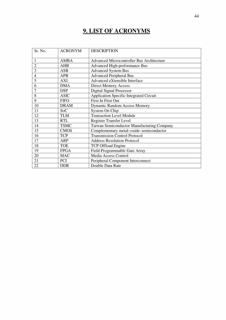
9. LIST OF ACRONYMS
Sr. No. ACRONYM DESCRIPTION
1 AMBA Advanced Microcontroller Bus Architecture
2 AHB Advanced High-performance Bus
3 ASB Advanced System Bus
4 APB Advanced Peripheral Bus
5 AXI Advanced eXtensible Interface
6 DMA Direct Memory Access
7 DSP Digital Signal Processor
8 ASIC Application Specific Integrated Circuit
9 FIFO First In First Out
10 DRAM Dynamic Random Access Memory
11 SoC System On Chip
12 TLM Transaction Level Module
13 RTL Register Transfer Level
14 TSMC Taiwan Semiconductor Manufacturing Company
15 CMOS Complementary metal–oxide–semiconductor
16 TCP Transmission Control Protocol
17 ARP Address Resolution Protocol
18 TOE TCP Offload Engine
19 FPGA Field-Programmable Gate Array
20 MAC Media Access Control
21 PCI Peripheral Component Interconnect
22 DDR Double Data Rate


![Introduction - interoperability.blob.core.windows.netMS-OFFDI]-160914.docx · Web view, by using Microsoft Word 2013, Microsoft Word 2010, Microsoft Office Word 2007, Microsoft](https://img.pdfslide.us/doc/110x75/5d51318488c993b0478b9899/introduction-ms-offdi-160914docx-web-view-by-using-microsoft-word-2013-microsoft.jpg)


![[MS-OFFDI]: Microsoft Office File Format Documentation … · 2017-09-19 · Microsoft Word 97 Microsoft Word 2000 Microsoft Word 2002 Microsoft Office Word 2003 Microsoft Office](https://img.pdfslide.us/doc/110x75/5edde022ad6a402d66691993/ms-offdi-microsoft-office-file-format-documentation-2017-09-19-microsoft-word.jpg)