Embed Size (px)
Citation preview
1
MMiiccrroossoofftt EExxcchhaannggee SSeerrvveerr 22000077 UUnniiffiieedd MMeessssaaggiinngg
PPBBXX CCoonnffiigguurraattiioonn NNoottee::
RRoollmm 99775511
wwiitthh DDiiaallooggiicc®® 11000000 MMeeddiiaa GGaatteewwaayy SSeerriieess
((DDMMGG11000088RRLLMMDDNNII)) uussiinngg DDiiggiittaall SSeett EEmmuullaattiioonn
By : Dialogic
Updated Since : 12/19/2007
READ THIS BEFORE YOU PROCEED
This document is for informational purposes only and is provided “AS IS”. Microsoft, its partners and vendors cannot verify the accuracy of this information and take no responsibility for the content of this document. MICROSOFT, ITS PARTNERS AND VENDORS MAKE NO WARRANTIES, EXPRESS, IMPLIED OR STATUTORY, AS TO THE INFORMATION IN THIS DOCUMENT.
2
Content This document describes the configuration required to setup Rolm 9751 and Dialogic® 1000 Media Gateway
Series (DMG1008RLMDNI) using digital set emulation as the telephony signaling protocol. It also contains
the results of the interoperability testing of Microsoft Exchange 2007 Unified Messaging based on this setup.
Intended Audience This document is intended for Systems Integrators with significant telephony knowledge.
Technical Support The information contained within this document has been provided by Microsoft partners or equipment manufacturers and is provided AS IS. This document contains information about how to modify the configuration of your PBX or VoIP gateway. Improper configuration may result in the loss of service of the PBX or gateway. Microsoft is unable to provide support or assistance with the configuration or troubleshooting of components described within. Microsoft recommends readers to engage the service of an Microsoft Exchange 2007 Unified Messaging Specialist or the manufacturers of the equipment(s) described within to assist with the planning and deployment of Exchange Unified Messaging.
Microsoft Exchange 2007 Unified Messaging (UM) Specialists These are Systems Integrators who have attended technical training on Exchange 2007 Unified Messaging conducted by Microsoft Exchange Engineering Team. For contact information, visit here.
Version Information
Date of Modification Details of Modification
December 19, 2007 Initial version of this document.
3
1. Components Information
1.1. PBX or IP-PBX
PBX Vendor Rolm
Model 9751
Software Version 9005
Telephony Signaling Digital set emulation
Additional Notes N/A
1.2. VoIP Gateway
Gateway Vendor Dialogic Corporation
Model Dialogic® 1000 Media Gateway Series (DMG1008RLMDNI)
Software Version 5.0.42
VoIP Protocol SIP
1.3. Microsoft Exchange Server 2007 Unified Messaging
Version RTM
2. Prerequisites
2.1. Gateway Requirements
The gateway needs to support RP400 (Rolmphone 400) digital station set emulation.
2.2. PBX Requirements
To support the 2-wire station interface as documented, you need the RLI-90678 line card.
2.3. Cabling Requirements
No specific cabling requirements have been noted.
4
3. Summary and Limitations
A check in this box indicates the UM feature set is fully functional when using the PBX/gateway
in question.
4. Gateway Setup Notes
During the initial setup of the gateway using the serial port, you must: • Assign the gateway a Unique IP address, subnet mask and network gateway address (if the
latter is required). • Configure the gateway to use the SIP VoIP protocol. • Configure the gateway for the Rolm integration.
During the solution-specific setup of the gateway using the web interface, you must: • Configure the gateway with at least a single IP endpoint pointing to your messaging server. If
multiple IP endpoints are to be used, then ensure they are configured as well. • Activate fault tolerance and load balancing as required by the application and system
requirements. • Specify the required audio coders as required by the application. • Set the hunt group extension number to the extension number you will be using for your
primary DN in the PBX programming. • Configure the SIP Transport for TCP.
5
5. PBX Setup Notes
The basic steps of setting up the PBX for use with this gateway and Exchange UM are as follows: • Setting up each gateway station port. • Defining hunt group to act as a central point for incoming calls to the gateway. • Setting up subscriber station sets.
The basic commands that you will encounter on the PBX to perform these actions are:
• MOD and CREATE
5.1. Setting Up Each Gateway Station Port
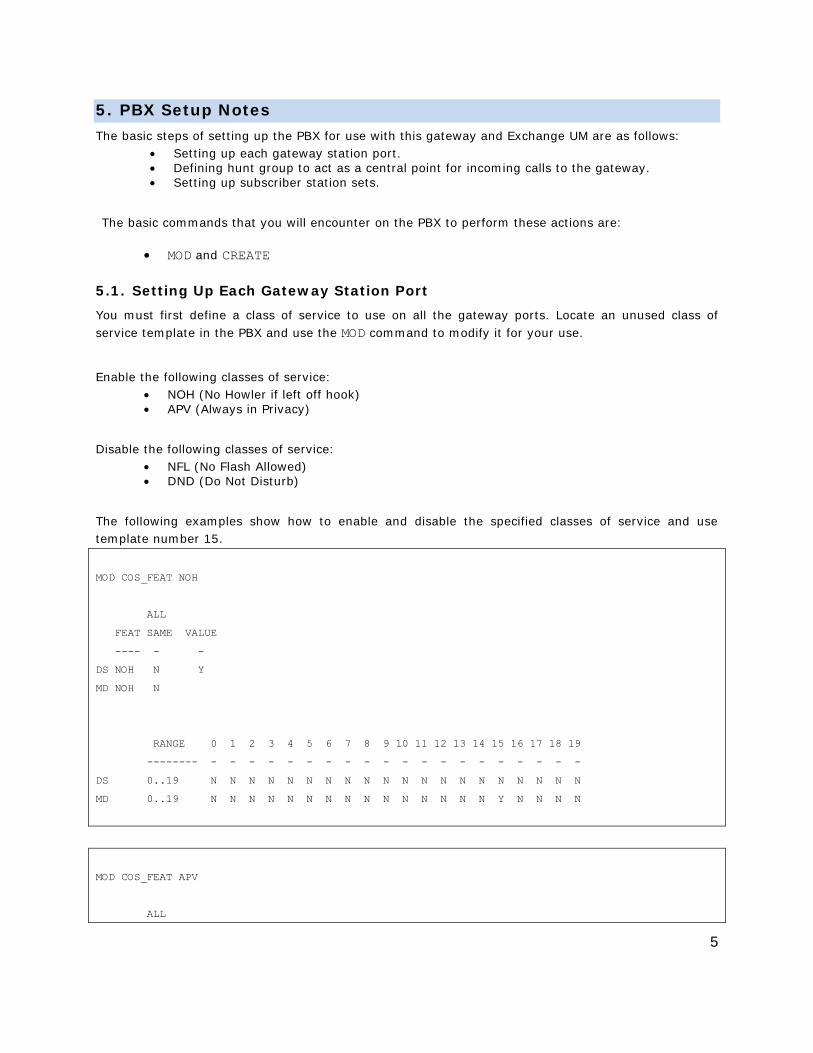
You must first define a class of service to use on all the gateway ports. Locate an unused class of service template in the PBX and use the MOD command to modify it for your use.
Enable the following classes of service: • NOH (No Howler if left off hook) • APV (Always in Privacy)
Disable the following classes of service: • NFL (No Flash Allowed) • DND (Do Not Disturb)
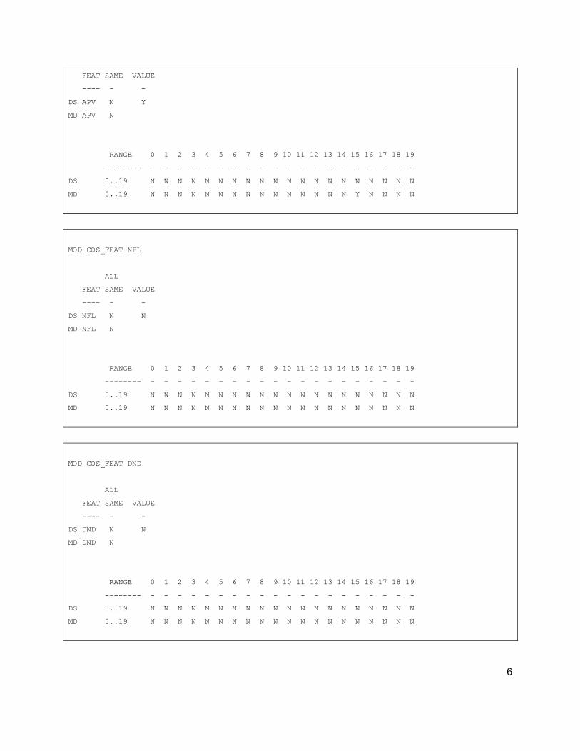
The following examples show how to enable and disable the specified classes of service and use template number 15.
MOD COS_FEAT NOH
ALL
FEAT SAME VALUE
---- - -
DS NOH N Y
MD NOH N
RANGE 0 1 2 3 4 5 6 7 8 9 10 11 12 13 14 15 16 17 18 19
-------- - - - - - - - - - - - - - - - - - - - -
DS 0..19 N N N N N N N N N N N N N N N N N N N N
MD 0..19 N N N N N N N N N N N N N N N Y N N N N
MOD COS_FEAT APV
ALL
6
FEAT SAME VALUE
---- - -
DS APV N Y
MD APV N
RANGE 0 1 2 3 4 5 6 7 8 9 10 11 12 13 14 15 16 17 18 19
-------- - - - - - - - - - - - - - - - - - - - -
DS 0..19 N N N N N N N N N N N N N N N N N N N N
MD 0..19 N N N N N N N N N N N N N N N Y N N N N
MOD COS_FEAT NFL
ALL
FEAT SAME VALUE
---- - -
DS NFL N N
MD NFL N
RANGE 0 1 2 3 4 5 6 7 8 9 10 11 12 13 14 15 16 17 18 19
-------- - - - - - - - - - - - - - - - - - - - -
DS 0..19 N N N N N N N N N N N N N N N N N N N N
MD 0..19 N N N N N N N N N N N N N N N N N N N N
MOD COS_FEAT DND
ALL
FEAT SAME VALUE
---- - -
DS DND N N
MD DND N
RANGE 0 1 2 3 4 5 6 7 8 9 10 11 12 13 14 15 16 17 18 19
-------- - - - - - - - - - - - - - - - - - - - -
DS 0..19 N N N N N N N N N N N N N N N N N N N N
MD 0..19 N N N N N N N N N N N N N N N N N N N N
7
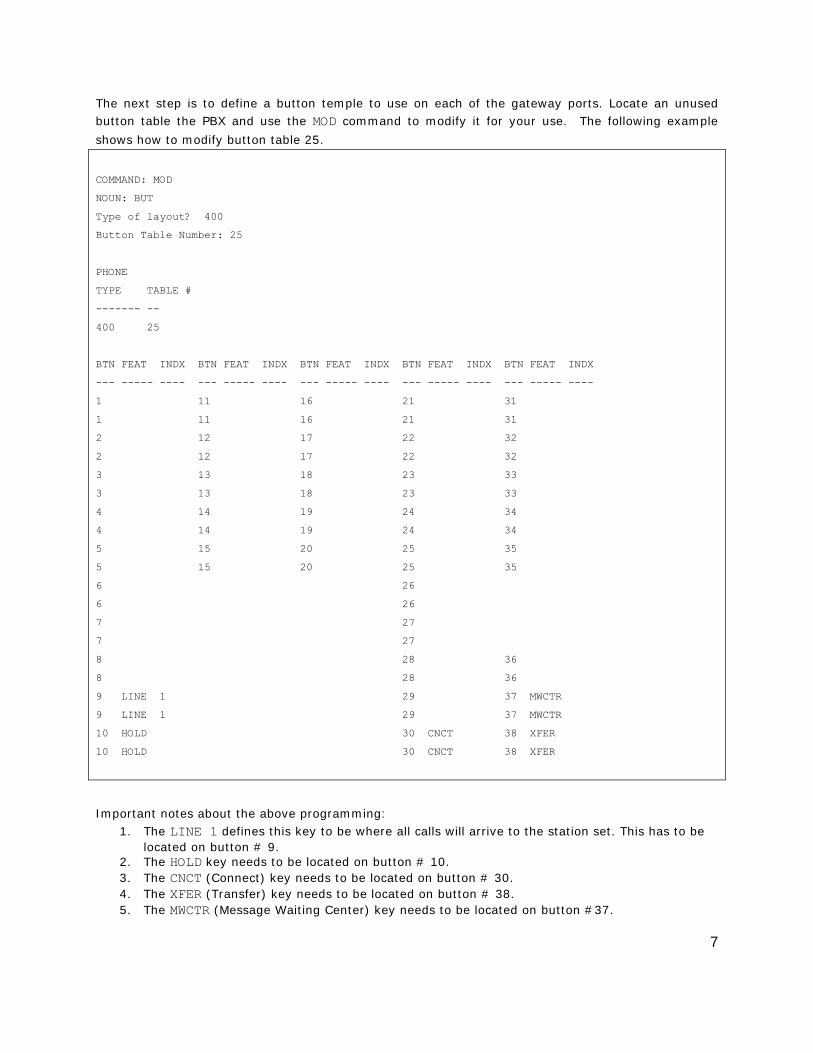
The next step is to define a button temple to use on each of the gateway ports. Locate an unused button table the PBX and use the MOD command to modify it for your use. The following example
shows how to modify button table 25.
COMMAND: MOD
NOUN: BUT
Type of layout? 400
Button Table Number: 25
PHONE
TYPE TABLE #
------- --
400 25
BTN FEAT INDX BTN FEAT INDX BTN FEAT INDX BTN FEAT INDX BTN FEAT INDX
--- ----- ---- --- ----- ---- --- ----- ---- --- ----- ---- --- ----- ----
1 11 16 21 31
1 11 16 21 31
2 12 17 22 32
2 12 17 22 32
3 13 18 23 33
3 13 18 23 33
4 14 19 24 34
4 14 19 24 34
5 15 20 25 35
5 15 20 25 35
6 26
6 26
7 27
7 27
8 28 36
8 28 36
9 LINE 1 29 37 MWCTR
9 LINE 1 29 37 MWCTR
10 HOLD 30 CNCT 38 XFER
10 HOLD 30 CNCT 38 XFER
Important notes about the above programming: 1. The LINE 1 defines this key to be where all calls will arrive to the station set. This has to be
located on button # 9. 2. The HOLD key needs to be located on button # 10. 3. The CNCT (Connect) key needs to be located on button # 30. 4. The XFER (Transfer) key needs to be located on button # 38. 5. The MWCTR (Message Waiting Center) key needs to be located on button #37.
8
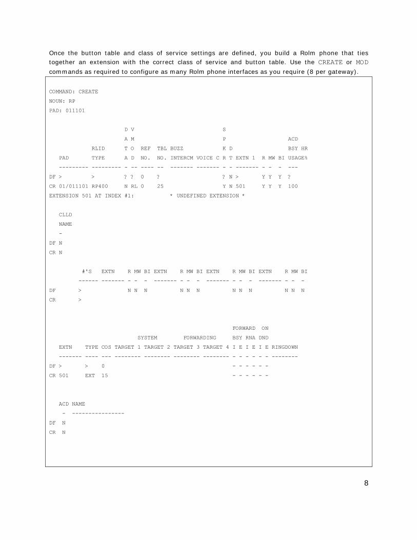
Once the button table and class of service settings are defined, you build a Rolm phone that ties together an extension with the correct class of service and button table. Use the CREATE or MOD
commands as required to configure as many Rolm phone interfaces as you require (8 per gateway).
COMMAND: CREATE
NOUN: RP
PAD: 011101
D V S
A M P ACD
RLID T O REF TBL BUZZ K D BSY HR
PAD TYPE A D NO. NO. INTERCM VOICE C R T EXTN 1 R MW BI USAGE%
--------- --------- - -- ---- -- ------- ------- - - ------- - - - ---
DF > > ? ? 0 ? ? N > Y Y Y ?
CR 01/011101 RP400 N RL 0 25 Y N 501 Y Y Y 100
EXTENSION 501 AT INDEX #1: * UNDEFINED EXTENSION *
CLLD
NAME
-
DF N
CR N
#'S EXTN R MW BI EXTN R MW BI EXTN R MW BI EXTN R MW BI
------ ------- - - - ------- - - - ------- - - - ------- - - -
DF > N N N N N N N N N N N N
CR >
FORWARD ON
SYSTEM FORWARDING BSY RNA DND
EXTN TYPE COS TARGET 1 TARGET 2 TARGET 3 TARGET 4 I E I E I E RINGDOWN
------- ---- --- -------- -------- -------- -------- - - - - - - --------
DF > > 0 - - - - - -
CR 501 EXT 15 - - - - - -
ACD NAME
- ----------------
DF N
CR N
9
Important notes about the above programming:
1. The station RLID TYPE section defines the type of station you are configuring. It must be set to RP400.
2. The TBL NO section sets the station to use the button table you want to use for this station. 3. The EXTN 1 section defines the extension number this station is going to be given. 4. The EXTN section defines the extension that is going to appear on the first line appearance. 5. The TYPE of the appearance must be configured as EXT, meaning that it is a physical
extension. 6. The COS section defines the class of service you wish your station to use.
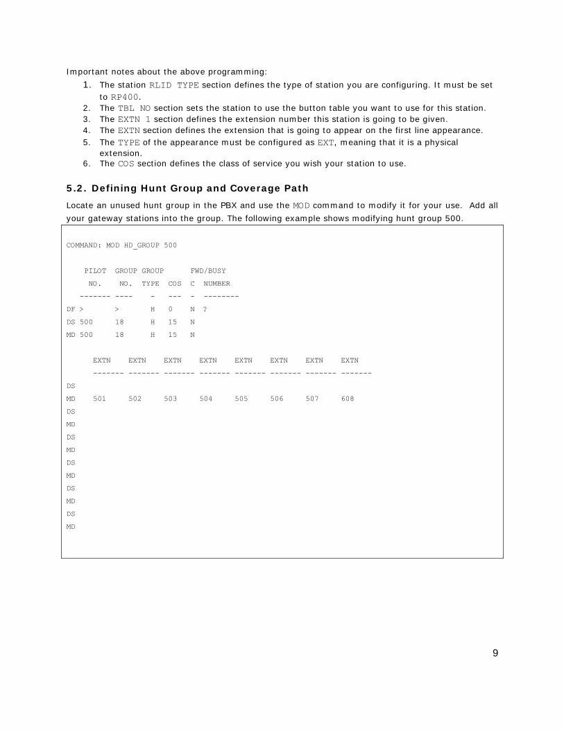
5.2. Defining Hunt Group and Coverage Path
Locate an unused hunt group in the PBX and use the MOD command to modify it for your use. Add all
your gateway stations into the group. The following example shows modifying hunt group 500.
COMMAND: MOD HD_GROUP 500
PILOT GROUP GROUP FWD/BUSY
NO. NO. TYPE COS C NUMBER
------- ---- - --- - --------
DF > > H 0 N ?
DS 500 18 H 15 N
MD 500 18 H 15 N
EXTN EXTN EXTN EXTN EXTN EXTN EXTN EXTN
------- ------- ------- ------- ------- ------- ------- -------
DS
MD 501 502 503 504 505 506 507 608
DS
MD
DS
MD
DS
MD
DS
MD
DS
MD
10
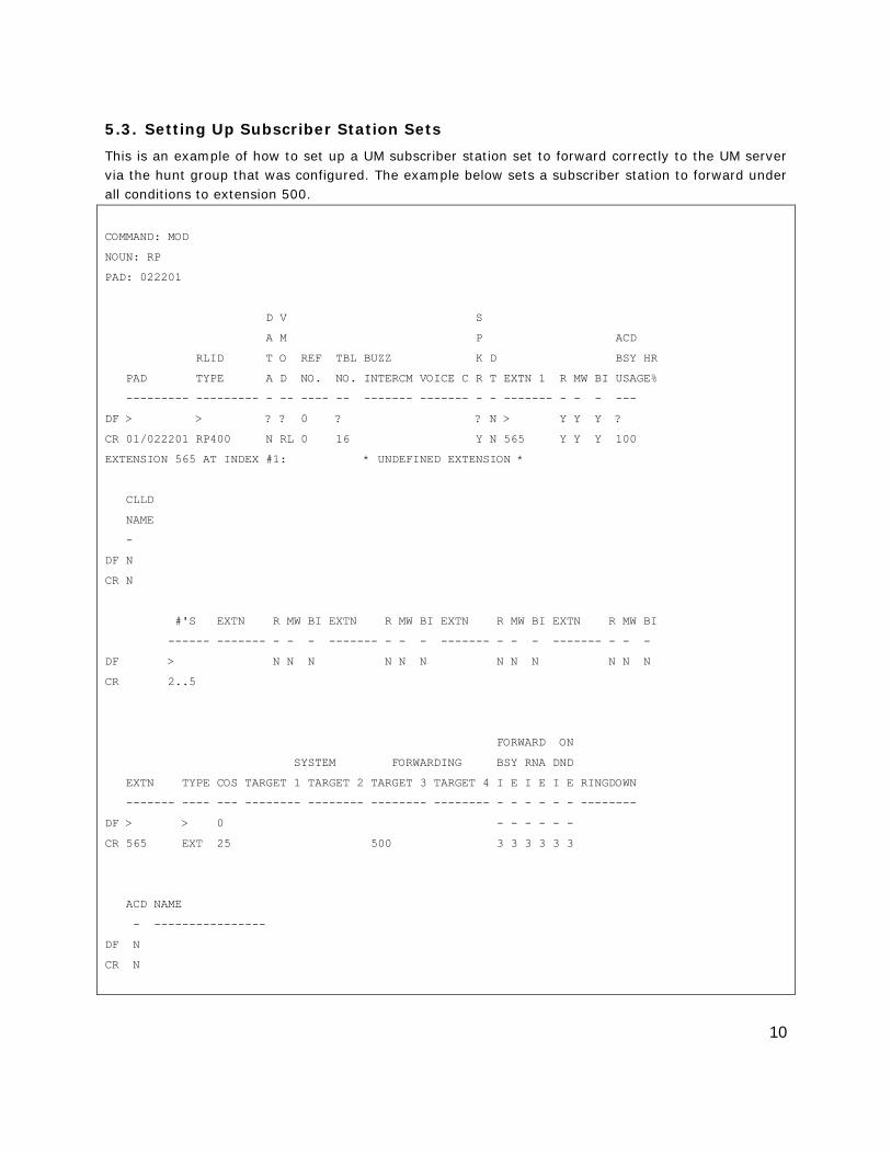
5.3. Setting Up Subscriber Station Sets
This is an example of how to set up a UM subscriber station set to forward correctly to the UM server via the hunt group that was configured. The example below sets a subscriber station to forward under all conditions to extension 500.
COMMAND: MOD
NOUN: RP
PAD: 022201
D V S
A M P ACD
RLID T O REF TBL BUZZ K D BSY HR
PAD TYPE A D NO. NO. INTERCM VOICE C R T EXTN 1 R MW BI USAGE%
--------- --------- - -- ---- -- ------- ------- - - ------- - - - ---
DF > > ? ? 0 ? ? N > Y Y Y ?
CR 01/022201 RP400 N RL 0 16 Y N 565 Y Y Y 100
EXTENSION 565 AT INDEX #1: * UNDEFINED EXTENSION *
CLLD
NAME
-
DF N
CR N
#'S EXTN R MW BI EXTN R MW BI EXTN R MW BI EXTN R MW BI
------ ------- - - - ------- - - - ------- - - - ------- - - -
DF > N N N N N N N N N N N N
CR 2..5
FORWARD ON
SYSTEM FORWARDING BSY RNA DND
EXTN TYPE COS TARGET 1 TARGET 2 TARGET 3 TARGET 4 I E I E I E RINGDOWN
------- ---- --- -------- -------- -------- -------- - - - - - - --------
DF > > 0 - - - - - -
CR 565 EXT 25 500 3 3 3 3 3 3
ACD NAME
- ----------------
DF N
CR N
11
Important notes about the above programming: 1. To set the forwarding destination of the station set, modify a station’s Forwarding Target
setting to direct calls to the hunt group extension created. 2. To define the forwarding pattern for the subscriber station, set the various forwarding patterns
(Forward BSY, RNA, DND) to use the target you defined for internal or external calls under each condition.
5.4. Additional Comments
You will notice that depending upon the various revisions of the 9005 software, the commands and screens may vary slightly. Consult your PBX programming guide for a complete listing of commands as needed. This document shows the basic steps needed, however, your actual commands may vary slightly.
12
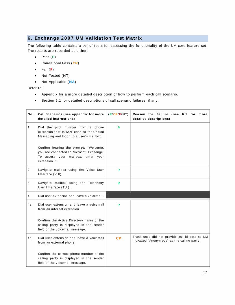
6. Exchange 2007 UM Validation Test Matrix
The following table contains a set of tests for assessing the functionality of the UM core feature set. The results are recorded as either:
• Pass (P)
• Conditional Pass (CP)
• Fail (F)
• Not Tested (NT)
• Not Applicable (NA)
Refer to:
• Appendix for a more detailed description of how to perform each call scenario.
• Section 6.1 for detailed descriptions of call scenario failures, if any.
No. Call Scenarios (see appendix for more detailed instructions)
(P/CP/F/NT) Reason for Failure (see 6.1 for more detailed descriptions)
1 Dial the pilot number from a phone extension that is NOT enabled for Unified Messaging and logon to a user’s mailbox.
Confirm hearing the prompt: “Welcome, you are connected to Microsoft Exchange. To access your mailbox, enter your extension…”
P
2 Navigate mailbox using the Voice User Interface (VUI).
P
3 Navigate mailbox using the Telephony User Interface (TUI).
P
4 Dial user extension and leave a voicemail.
4a Dial user extension and leave a voicemail from an internal extension.
Confirm the Active Directory name of the calling party is displayed in the sender field of the voicemail message.
P
4b Dial user extension and leave a voicemail from an external phone.
Confirm the correct phone number of the calling party is displayed in the sender field of the voicemail message.
CP Trunk used did not provide call id data so UM indicated “Anonymous” as the calling party.
13
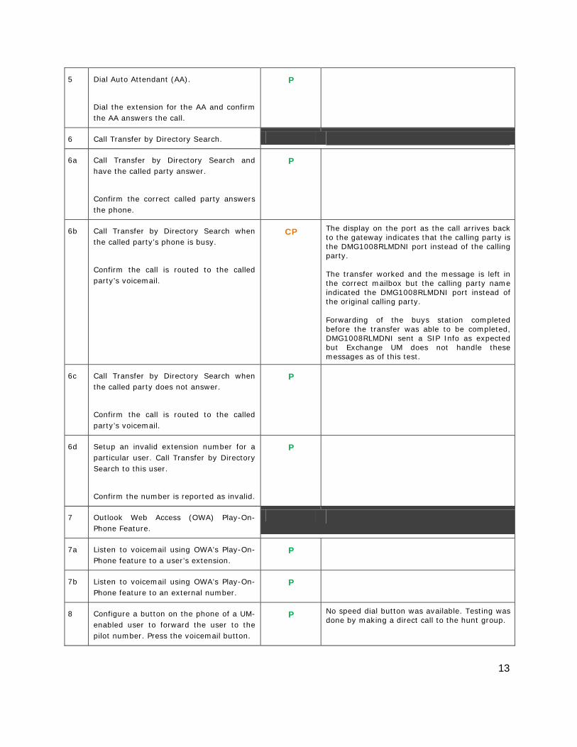
5 Dial Auto Attendant (AA).
Dial the extension for the AA and confirm the AA answers the call.
P
6 Call Transfer by Directory Search.
6a Call Transfer by Directory Search and have the called party answer.
Confirm the correct called party answers the phone.
P
6b Call Transfer by Directory Search when the called party’s phone is busy.
Confirm the call is routed to the called party’s voicemail.
CP The display on the port as the call arrives back to the gateway indicates that the calling party is the DMG1008RLMDNI port instead of the calling party. The transfer worked and the message is left in the correct mailbox but the calling party name indicated the DMG1008RLMDNI port instead of the original calling party. Forwarding of the buys station completed before the transfer was able to be completed, DMG1008RLMDNI sent a SIP Info as expected but Exchange UM does not handle these messages as of this test.
6c Call Transfer by Directory Search when the called party does not answer.
Confirm the call is routed to the called party’s voicemail.
P
6d Setup an invalid extension number for a particular user. Call Transfer by Directory Search to this user.
Confirm the number is reported as invalid.
P
7 Outlook Web Access (OWA) Play-On-Phone Feature.
7a Listen to voicemail using OWA’s Play-On-Phone feature to a user’s extension.
P
7b Listen to voicemail using OWA’s Play-On-Phone feature to an external number.
P
8 Configure a button on the phone of a UM-enabled user to forward the user to the pilot number. Press the voicemail button.
P No speed dial button was available. Testing was done by making a direct call to the hunt group.
14
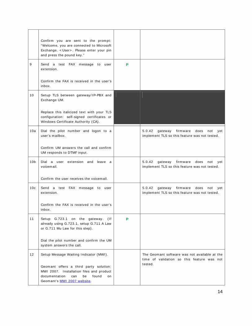
Confirm you are sent to the prompt: “Welcome, you are connected to Microsoft Exchange. <User>. Please enter your pin and press the pound key.”
9 Send a test FAX message to user extension.
Confirm the FAX is received in the user’s inbox.
P
10 Setup TLS between gateway/IP-PBX and Exchange UM.
Replace this italicized text with your TLS configuration: self-signed certificates or Windows Certificate Authority (CA).
10a Dial the pilot number and logon to a user’s mailbox.
Confirm UM answers the call and confirm UM responds to DTMF input.
5.0.42 gateway firmware does not yet implement TLS so this feature was not tested.
10b Dial a user extension and leave a voicemail.
Confirm the user receives the voicemail.
5.0.42 gateway firmware does not yet implement TLS so this feature was not tested.
10c Send a test FAX message to user extension.
Confirm the FAX is received in the user’s inbox.
5.0.42 gateway firmware does not yet implement TLS so this feature was not tested.
11 Setup G.723.1 on the gateway. (If already using G.723.1, setup G.711 A Law or G.711 Mu Law for this step).
Dial the pilot number and confirm the UM system answers the call.
P
12 Setup Message Waiting Indicator (MWI).
Geomant offers a third party solution: MWI 2007. Installation files and product documentation can be found on Geomant’s MWI 2007 website.
The Geomant software was not available at the time of validation so this feature was not tested.
15
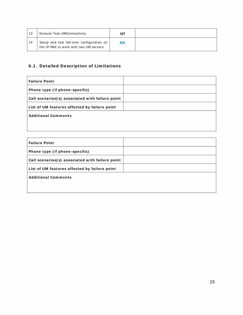
13 Execute Test-UMConnectivity. NT
14 Setup and test fail-over configuration on the IP-PBX to work with two UM servers.
NA
6.1. Detailed Description of Limitations
Failure Point
Phone type (if phone-specific)
Call scenarios(s) associated with failure point
List of UM features affected by failure point
Additional Comments
Failure Point
Phone type (if phone-specific)
Call scenarios(s) associated with failure point
List of UM features affected by failure point
Additional Comments
16
7. Troubleshooting
7.1. Important Debugging Tools
• Ethereal/Wireshark – Used to view and analyze the network captures provided by the Dialogic® gateway diagnostic firmware.
• Adobe Audition -- Used to review and analyze the audio extracted from the network captures to troubleshoot any audio-related issues.
7.2. Important Gateway Trace Masks
These keys are helpful during troubleshooting scenarios and should be considered keys to activate by default for all troubleshooting cases.
• voip prot and voip code – this allows the collection of all SIP-related messages as they are sent from and received by the gateway. This data is important in cases where you feel that the gateway is not able to communicate properly with the messaging server.
• tel event and tel code – This allows the collection of circuit-side activity of the emulated station set, such as display updates, key presses, light transitions and hook state changes. This data is important in the following scenarios:
o Call control problems (dropped calls, failing transfers, etc…)
o Integration problems (incorrect mailbox placement, missed auto-attendant greetings etc…)
These keys are helpful during specific issues and can be enabled for targeted troubleshooting of very specific cases. Activation of these keys may generate large amounts of data on busy systems and increase the size of the collected log files, but should not harm system performance.
• dspcpi (all keys) – This allows the collection of tone-related data. This data is helpful in cases where you think you have problems detecting specific tones that should be, should not be, or are expected to be present at specific times during the call. If you do not suspect a tone-related issue, this key may be left disabled. This data is important in the following scenarios:
o Failing transfers
o Failing outbound calls (play to phone)
o Dropped calls (callers cut off while leaving messages, etc…)
• adept (all keys) – This allows the collection of rule-parsing data. This data is required in the troubleshooting of integration-related issues.
NOTE: Turning on all traces is not recommended. Doing this floods the debug stream with significant amounts of information that can cause delays in determining the root cause of a problem.
17
Appendix
1. Dial Pilot Number and Mailbox Login
• Dial the pilot number of the UM server from an extension that is NOT enabled for UM.
• Confirm hearing the greeting prompt: “Welcome, you are connected to Microsoft Exchange. To access your mailbox, enter your extension...”
• Enter the extension, followed by the mailbox PIN of an UM-enabled user.
• Confirm successful logon to the user’s mailbox.
2. Navigate Mailbox using Voice User Interface (VUI)
• Logon to a user’s UM mailbox.
• If the user preference has been set to DTMF tones, activate the Voice User Interface (VUI) under personal options.
• Navigate through the mailbox and try out various voice commands to confirm that the VUI is working properly.
• This test confirms that the RTP is flowing in both directions and speech recognition is working properly.
3. Navigate Mailbox using Telephony User Interface (TUI)
• Logon to a user’s UM mailbox.
• If the user preference has been set to voice, press “#0” to activate the Telephony User Interface (TUI).
• Navigate through the mailbox and try out the various key commands to confirm that the TUI is working properly.
• This test confirms that both the voice RTP and DTMF RTP (RFC 2833) are flowing in both directions.
4. Dial User Extension and Leave Voicemail
• Note: If you are having difficulty reaching the user’s UM voicemail, verify that the coverage path for the UM-enabled user’s phone is set to the pilot number of the UM server.
a. From an Internal Extension
• From an internal extension, dial the extension for a UM-enabled user and leave a voicemail message.
• Confirm the voicemail message arrives in the called user’s inbox.
• Confirm this message displays a valid Active Directory name as the sender of this voicemail.
18
b. From an External Phone
• From an external phone, dial the extension for a UM-enabled user and leave a voicemail message.
• Confirm the voicemail message arrives in the called user’s inbox.
• Confirm this message displays the phone number as the sender of this voicemail.
5. Dial Auto Attendant(AA)
• Create an Auto Attendant using the Exchange Management Console:
• Under the Exchange Management Console, expand “Organizational Configuration” and then click on “Unified Messaging”.
• Go to the Auto Attendant tab under the results pane.
• Click on the “New Auto Attendant…” under the action pane to invoke the AA wizard.
• Associate the AA with the appropriate dial plan and assign an extension for the AA.
• Create PBX dialing rules to always forward calls for the AA extension to the UM server.
• Confirm the AA extension is displayed in the diversion information of the SIP Invite.
• Dial the extension of Auto Attendant.
• Confirm the AA answers the call.
6. Call Transfer by Directory Search
• Method one: Pilot Number Access
• Dial the pilot number for the UM server from a phone that is NOT enabled for UM.
• To search for a user by name:
• Press # to be transferred to name Directory Search.
• Call Transfer by Directory Search by entering the name of a user in the same Dial Plan using the telephone keypad, last name first.
• To search for a user by email alias:
• Press “#” to be transferred to name Directory Search
• Press “# #” to be transferred to email alias Directory Search
• Call Transfer by Directory Search by entering the email alias of a user in the same Dial Plan using the telephone keypad, last name first.
• Method two: Auto Attendant
• Follow the instructions in appendix section 5 to setup the AA.
• Call Transfer by Directory Search by speaking the name of a user in the same Dial Plan. If the AA is not speech enabled, type in the name using the telephone keypad.
19
• Note: Even though some keys are associated with three or four numbers, for each letter, each key only needs to be pressed once regardless of the letter you want. Ignore spaces and symbols when spelling the name or email alias.
a. Called Party Answers
• Call Transfer by Directory Search to a user in the same dial plan and have the called party answer.
• Confirm the call is transferred successfully.
b. Called Party is Busy
• Call Transfer by Directory Search to a user in the same dial plan when the called party is busy.
• Confirm the calling user is routed to the correct voicemail.
c. Called Party does not Answer
• Call Transfer by Directory Search to a user in the same dial plan and have the called party not answer the call.
• Confirm the calling user is routed to the correct voicemail.
d. The Extension is Invalid
• Assign an invalid extension to a user in the same dial plan. An invalid extension has the same number of digits as the user’s dial plan and has not been mapped on the PBX to any user or device.
• UM Enable a user by invoking the “Enable-UMMailbox” wizard.
• Assign an unused extension to the user.
• Do not map the extension on the PBX to any user or device.
• Call Transfer by Directory Search to this user.
• Confirm the call fails and the caller is prompted with appropriate messages.
7. Play-On-Phone
• To access play-on-phone:
• Logon to Outlook Web Access (OWA) by going to URL https://<server name>/owa.
• After receiving a voicemail in the OWA inbox, open this voicemail message.
• At the top of this message, look for the Play-On-Phone field ( Play on Phone...).
• Click this field to access the Play-On-Phone feature.
a. To an Internal Extension
• Dial the extension for a UM-enabled user and leave a voicemail message.
• Logon to this called user’s mailbox in OWA.
20
• Once it is received in the user’s inbox, use OWA’s Play-On-Phone to dial an internal extension.
• Confirm the voicemail is delivered to the correct internal extension.
b. To an External Phone number
• Dial the extension for a UM-enabled user and leave a voicemail message.
• Logon to the UM-enabled user’s mailbox in OWA.
• Confirm the voicemail is received in the user’s mailbox.
• Use OWA’s Play-On-Phone to dial an external phone number.
• Confirm the voicemail is delivered to the correct external phone number.
• Troubleshooting:
• Make sure the appropriate UMMailboxPolicy dialing rule is configured to make this call. As an example, open an Exchange Management Shell and type in the following commands:
• $dp = get-umdialplan -id <dial plan ID>
• $dp.ConfiguredInCountryOrRegionGroups.Clear()
• $dp.ConfiguredInCountryOrRegionGroups.Add("anywhere,*,*,")
• $dp.AllowedInCountryOrRegionGroups.Clear()
• $dp.AllowedInCountryOrRegionGroups.Add(“anywhere")
• $dp|set-umdialplan
• $mp = get-ummailboxpolicy -id <mailbox policy ID>
• $mp.AllowedInCountryGroups.Clear()
• $mp.AllowedInCountryGroups.Add("anywhere")
• $mp|set-ummailboxpolicy
• The user must be enabled for external dialing on the PBX.
• Depending on how the PBX is configured, you may need to prepend the trunk access code (e.g. 9) to the external phone number.
8. Voicemail Button
• Configure a button on the phone of a UM-enabled user to route the user to the pilot number of the UM server.
• Press this voicemail button on the phone of an UM-enabled user.
• Confirm you are sent to the prompt: “Welcome, you are connected to Microsoft Exchange. <User Name>. Please enter your pin and press the pound key.”
• Note: If you are not hearing this prompt, verify that the button configured on the phone passes the user’s extension as the redirect number. This means that the user extension should appear in the diversion information of the SIP invite.
21
9. FAX
• Use the Management Console or the Management Shell to FAX-enable a user.
• Management Console:
• Double click on a user’s mailbox and go to Mailbox Features tab.
• Click Unified Messaging and then click the properties button.
• Check the box “Allow faxes to be received”.
• Management Shell - execute the following command:
• Set-UMMailbox –identity UMUser –FaxEnabled:$true
• To test fax functionality:
• Dial the extension for this fax-enabled UM user from a fax machine.
• Confirm the fax message is received in the user’s inbox.
• Note: You may notice that the UM server answers the call as though it is a voice call (i.e. you will hear: “Please leave a message for…”). When the UM server detects the fax CNG tones, it switches into fax receiving mode, and the voice prompts terminate.
• Note: UM only support T.38 for sending fax.
10. TRANSPORT SECURITY LAYER (TLS)
• Setup TLS on the gateway/IP-PBX and Exchange 2007 UM.
• Import/Export all the appropriate certificates.
a. Dial Pilot Number and Mailbox Login
• Execute the steps in scenario 1 (above) with TLS turned on.
b. Dial User Extension and Leave a Voicemail
• Execute the steps in scenario 4 (above) with TLS turned on.
c. FAX
• Execute the steps in scenario 9 (above) with TLS turned on.
11. G.723.1
• Configure the gateway to use the G.723.1 codec for sending audio to the UM server.
• If already using G.723.1 for the previous set of tests, use this step to test G.711 A Law or G.711 Mu Law instead.
• Call the pilot number and verify the UM server answers the call.
• Note: If the gateway is configured to use multiple codecs, the UM server, by default, will use the G.723.1 codec if it is available.
22
12. Message Waiting Indicator (MWI)
• Although Exchange 2007 UM does not natively support MWI, Geomant has created a 3rd party solution - MWI2007. This product also supports SMS message notification.
• Installation files and product documentation can be found on Geomant’s MWI 2007 website.
13. Test-UMConnectivity
• Run the Test-UMConnectivity diagnostic cmdlet by executing the following command in Exchange Management Shell:
• Test-UMConnectivity –UMIPGateway:<Gateway> -Phone:<Phone> |fl
• <Gateway> is the name (or IP address) of the gateway which is connected to UM, and through which you want to check the connectivity to the UM server. Make sure the gateway is configured to route calls to UM.
• <Phone> is a valid UM extension. First, try using the UM pilot number for the hunt-group linked to the gateway. Next, try using a CFNA number configured for the gateway. Please ensure that a user or an AA is present on the UM server with that number.
• The output shows the latency and reports if it was successful or there were any errors.
14. Test Fail-Over Configuration on IP-PBX with Two UM Servers
• This is only required for direct SIP integration with IP-PBX. If the IP-PBX supports fail-over configuration (e.g., round-robin calls between two or more UM servers):
• Provide the configuration steps in Section 5.
• Configure the IP-PBX to work with two UM servers.
• Simulate a failure in one UM server.
• Confirm the IP-PBX transfers new calls to the other UM server successfully.


![[School] Magazine: Unused Images](https://img.pdfslide.us/doc/110x75/558e49c91a28ab75518b4747/school-magazine-unused-images.jpg)