Embed Size (px)
Citation preview
INSTRUCTIONS
DP73MICROSCOPE DIGITAL CAMERA
This instruction manual is for the Olympus Microscope Digital Camera Model DP73. To ensure the safety, obtain optimum performance and familiarize yourself fully with the use of this camera, we recommend that you study this manual thoroughly before operating the camera.For image operations including recording, editing and saving, please refer to the online manual for the cellSens / OLYMPUS Stream Software.Retain this instruction manual in an easily accessible place near the work desk for future reference.
A X 8 0 8 0

This device complies with the requirements of both directive 2004/108/EC concerning electro-
magnetic compatibility and directive 2006/95/EC concerning low voltage.
In accordance with European Directive 2002/96/EC on Waste Electrical and Electronic Equip-
ment, this symbol indicates that the product must not be disposed of as unsorted municipal
waste, but should be collected separately.
Refer to your local Olympus distributor in EU for return and/or collection systems available in your
country.
NOTE: This equipment has been tested and found to comply with the limits for a Class A digital device,
pursuant to Part 15 of the FCC Rules. These limits are designed to provide reasonable protection
against harmful interference when the equipment is operated in a commercial environment. This
equipment generates, uses, and can radiate radio frequency energy and, if not installed and used in
accordance with the instruction manual, may cause harmful interference to radio communications.
Operation of this equipment in a residential area is likely to cause harmful interference in which case
the user will be required to correct the interference at his own expense.
FCC WARNING: Changes or modifications not expressly approved by the party responsible for compliance
could void the user’s authority to operate the equipment.

DP73
CONTENTS
IMPORTANT — Be sure to read this chapter for safe use of the equipment. — 1-11
1 Intended Use ...........................................................................................................................................................................................................................................................5
2 Conformity of the System .........................................................................................................................................................................................................................5
3 Handling Precautions ...................................................................................................................................................................................................................................13
4 Maintenance and Storage ......................................................................................................................................................................................................................14
1 SYSTEM CHART ....................................................................................................................................................................................................15
2 NOMENCLATURE ...............................................................................................................................................................................................16
2-1 DP73/DP73 (For Desktop Computer) ................................................................................................................................................................................................16
2-2 [OPTIONAL] DP-PXU PCIe Extension Unit (For Laptop Computer) ............................................................................................................18
3 HARDWARE INSTALLATION ....................................................................................................................................................................19
1 Installing the Low-Profile Bracket ...................................................................................................................................................................................................19
2 Installing the PCIe Interface Board ..............................................................................................................................................................................................19
3 Installing the Camera Head ..................................................................................................................................................................................................................23
4 Connecting the Cables ..............................................................................................................................................................................................................................25
DP73
4 SOFTWARE INSTALLATION ......................................................................................................................................................................29
5 IMAGE ACQUISITION PROCEDURE ..........................................................................................................................................31
6 EXTERNAL TRIGGERING ..........................................................................................................................................................................33
7 SPECIFICATIONS ..................................................................................................................................................................................................35
9 TROUBLESHOOTING GUIDE ..............................................................................................................................................................40
1
The DP73 microscope digital camera is designed to be connected to a camera adapter mounted on an
Olympus UIS2/UIS series of optical microscope (not applicable to the LB series) for use in recording of
microscopic magnified images at high speed and highest resolution while maintaining high picture quality
and high color reproduction. The DP73 incorporates a variety of functions for supporting image recording
under optimum conditions.
When the DP73 microscope digital camera is used with a camera adapter or a microscope from a
manufacturer other than Olympus, the optical performance may not be manifested fully.
IMPORTANT
If the equipment is used in a manner not specified by this manual, the safety of the user may be endangered.
In addition, the equipment may also be damaged. Always use the equipment as outlined in this instruction
manual.
The following symbols are used to set off text in this instruction manual.
CAUTION : Indicates a potentially hazardous situation which, if not avoided, may result in minor or moderate injury or damage to the equipment or other property. It may also be used to alert against unsafe practices.
: Indicates commentary (for ease of operation and maintenance).
2
DP73
Never connect or disconnect the interface cable while the standby switch of the computer is set to
ON. Otherwise, malfunction may result.
1. Before connecting or disconnecting the interface cable, make sure that the standby switch of the com-
puter is set to OFF.
When connecting the interface cable, push in the connector all the way and ensure that the connector will
not slip out before setting the standby switch to ON.
Do not move the computer or apply an impact to it while it is powered ON.
2. The cords and interface cables are vulnerable to bends or twists. Do not apply excessive force to them.
3. To prevent the microscope from toppling down, avoid using microscope attachments that may make the total
height of the microscope above 1 meter when they are attached.
4. When installing the PCIe interface board, be sure to hold it by the edge. Never touch the board surface
directly, as this will lead to malfunction.
CAUTION
SAFETY PRECAUTIONS
3
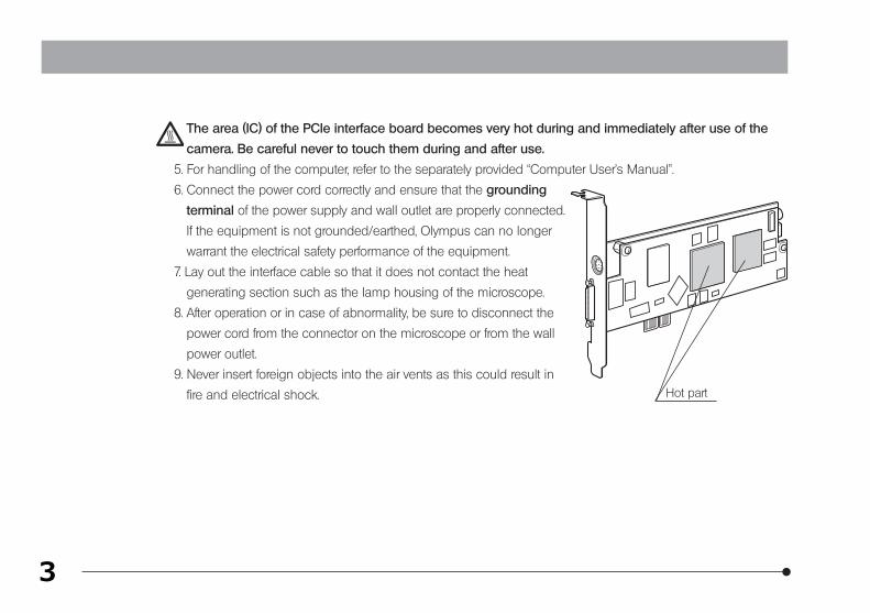
The area (IC) of the PCIe interface board becomes very hot during and immediately after use of the
camera. Be careful never to touch them during and after use.
5. For handling of the computer, refer to the separately provided “Computer User’s Manual”.
6. Connect the power cord correctly and ensure that the grounding
terminal of the power supply and wall outlet are properly connected.
If the equipment is not grounded/earthed, Olympus can no longer
warrant the electrical safety performance of the equipment.
7. Lay out the interface cable so that it does not contact the heat
generating section such as the lamp housing of the microscope.
8. After operation or in case of abnormality, be sure to disconnect the
power cord from the connector on the microscope or from the wall
power outlet.
9. Never insert foreign objects into the air vents as this could result in
fire and electrical shock. Hot part
4
DP73
Computer and Software
The computer data may be destroyed by an unexpected event. Be sure to keep a backup of the data.
1. Olympus will not assume any liabilities for any damage incurred due to the use or non-usability of this
system, including compensation for the lost data.
2. The computer used with this system should set up and run Microsoft Windows 7 Professional or Ultimate.
For the OS in the computer, the user is requested to create a backup and retain it carefully. (Olympus does
not support the matters related to the OS including its backup.)
For details on the computer and Microsoft Windows 7, refer to their respective manuals.
3. Olympus guarantees the quality of this product in the factory shipment condition.
Olympus will not assume any liabilities for the operation errors and functional faults incurred due to the altera-
tion of the environmental setup (including BIOS change), installation of other software or addition of hardware
to the computer by the user.
4. When the HDD free space reduces, the data processing speed may slow extremely or errors may occur
frequently. To prevent this, delete unnecessary data files frequently. For how to delete data files, refer to the
manuals for Microsoft Windows 7.
5. Never attempt to delete or rename the folders and files installed by the provided installer software. Otherwise,
the software may get unable to be started up.
5
6. Do not open the housing of the computer and touch the power supply or the circuit board’s heat generating
section right after use as it may burn your hand. Wait until the internal temperature drops sufficiently.
7. Sharp edges inside the computer may cut your fingers, so take extra care.
8. Use a computer that complies with the safety standards of your country.
1 Intended Use
This device is intended to be used for the capture of digital images for non-clinical diagnostic purposes.
Restrictions in Use
1. The applicable camera adapter is the U-TV0.5XC-3, U-TV0.63XC-1-2, MVX-TV0.63XC, U-TV1XC or the combina-
tion of U-TV1X-2 and U-CMAD3.
The U-TV0.5XC should not be used because it deteriorates the image flatness.
A camera adapter with a magnification below 0.5X cannot be used because part of image will be obscured.
2. When the DP73 is connected to the rear port of the U-DPT(double port tube) or U-MPH(multi port head), the
peripheral part of the recorded image may be deteriorated due to the optical performance of the U-DPT or
U-MPH.
2 Conformity of the System
6
DP73
3. When the U-TV0.5/C-2/U-TV0.5/C-3/U-TV0.63XC-1-2(C mount camera adapter) is used, using two or more
intermediate attachments* may obscure the peripheral part of the field of view or may make flare noticeable.
* Example of two intermediate attachments with BX microscope :
Reflected light illuminator + intermediate attachment equivalent to the U-CA.
4. Under fluorescent ring illumination or other AC-driven illumination such as a phase control light intensity
adjusting illumination system, the following phenomena may be observed by illumination light flickering
because of high light intensity and shortened exposure time :
· Flickering of the displayed image.
· Instability in exposure.
· Hatching patterns in pixel shift recording (4800 x 3600 or 2400 x 1800 pixels, 3CCD mode).
However, provided that the brightness can be adjusted using the light intensity control knob or ND filters, the
above phenomena may be attenuated by adjusting the brightness so that the exposure time exceeds 1/50
sec.
For details on the microscope models using AC-driven illumination, contact Olympus.
5. Combinations of this product and non-Olympus microscopes have not been evaluated extensively.
Non-Olympus microscopes and commercially available C-mount lenses can be used provided that they
match a CCD with a size of no less than 1/1.8 inch and the lens projection length from the C-mount body
attaching section is no more than 4.5 mm. However, problems due to optical adaptability, such as shading,
may be observed.
7
6. When the specimen has a low contrast (near transparent) or high reflectance (mirror status) and the aperture
iris diaphragm is stopped down near the smallest aperture, spot flare may be noticeable.
7. When the edge of a non-transmitting object is observed under the STM6 (small measuring microscope)
transmitted illumination, flare may be noticeable due to the difference in brightness between the transmitted
sections (over-exposure) and non-transmitting sections (under-exposure). To reduce the flare, set a lower
exposure using the exposure correction function or setting the exposure manually.
8. When a low-power objective (below 4X) is used, the peripheral part of the field of view may be obscured. In
this case, use an ultralow-magnification condenser (U-ULC-2).
9. When the U-CFU (real time confocal unit) is used, it is required to set the exposure to a longer period than
1/30 sec. using the manual exposure mode and control the brightness by engaging or disengaging ND
filters.
10. When the specimen has large difference in brightness, particularly when the bright part of the specimen
comes on the upper part of the image, red and horizontal flare may be observed. It is noticeable when the
AS is being closed. The flare will get unnoticeable when the AS is being opened, though the flare may not be
completely removed.
11. When a specimen with high reflectivity is observed with reflected light brightfield observation through the
beam splitter of the eyepiece/camera light path of a trinocular tube in combination with the U-TV0.5XC
camera adapter, the image in the area outside the CCD’s effective image pickup area may be observed as
vague ghosts in the peripheral area of the visual field of eyepiece.
8
DP73
12. Flare may be produced during reflected light darkfield observation under overexposure To reduce the flare,
use the exposure correction function or reduce the exposure with manual exposure control.
13. During image acquisition with pixel shifting (4800 x 3600 or 2400 x 1800 pixels, 3CCD mode), the image may
be disturbed if the specimen is moved.
14. If the camera or microscope is vibrated during image acquisition with pixel shifting (44800 x 3600 or 2400 x
1800 pixels, 3CCD mode), the image will be disturbed. There are several causes for the vibration which are,
the operation of keyboard/mouse on the same table where microscope equipped with the camera is placed,
vibration from the instrument erquipped with air cooling fan, etc.
Operating Environment
Temperature: 10 to 35°C.
Humidity: 20% to 85% (without condensation).
See page 39 for details.
Recommended Monitor Specifications
· A monitor with the 1280 x 1024 or larger full-color display capability.
· An Adobe RGB compatible monitor, provided that the camera head is used in the Adobe RGB mode.
9
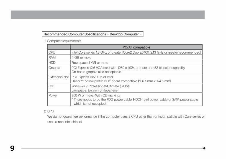
Recommended Computer Specifications – Desktop Computer –
1. Computer requirements
PC/AT compatible
CPU Intel Core series 1.8 GHz or greater [Core2 Duo E6400, 2.13 GHz or greater recommended]
RAM 4 GB or more
HDD Free space 1 GB or more
Graphic PCI Express X16 VGA card with 1280 x 1024 or more and 32-bit color capability.On-board graphic also acceptable.
Extension slot PCI Express Rev. 1.0a or later.Half-size or low-profile PCIe board compatible (106.7 mm x 174.6 mm)
OS Windows 7 Professional/Ultimate (64 bit)Language: English or Japanese
Power 250 W or more. (With CE marking)* There needs to be the FDD power cable, HDD(4-pin) power cable or SATA power cable
which is not occupied.
2. CPU
We do not guarantee performance if the computer uses a CPU other than or incompatible with Core series or
uses a non-Intel chipset.
10
DP73
3. HDD free space
The HDD free space (the value 1GB or more in Page 9) is the space that does not cause a special problem
when the system is installed or run. The space required for saving an image file in the HDD is slightly more
than 5.6 MB with a 1600 x 1200-pixel (24-bit) non-compressed image and slightly more than 50 MB with a
4800 x 3600-pixel (24-bit) non-compressed image. In consequence, the HDD should also provide a consider-
ably large space for saving these image files.
When saving movies in the HDD stack, the space required for saving a movie is about 80 MB (max.) per
second. The movie recording time is limited according to the HDD free space.
4. RAM
If a RAM other than a PC2700 or greater, dual-channel RAM is used, the full-size live frame rate may drop.
5. Monitor
Us an Adobe RGB compatible monitor when using the camera head in the Adobe RGB mode.
Optimum color reproduction is not available if the sRGB/Adobe RGB setting of the camera head does not
match the setting of the monitor.
6. Sequential connection of PCIe units
Up to two PCIe units including the DP73 and a PCI interface board of the DP72/DP71/DP70/DP30BW or
FV1000 (FV10-ASW-V1.5 or later) can be connected in series. Series connection of the FV300/FV500 is not
possible.
However, their simultaneous operation is not available so it is required to select either PCI interface operation.
11
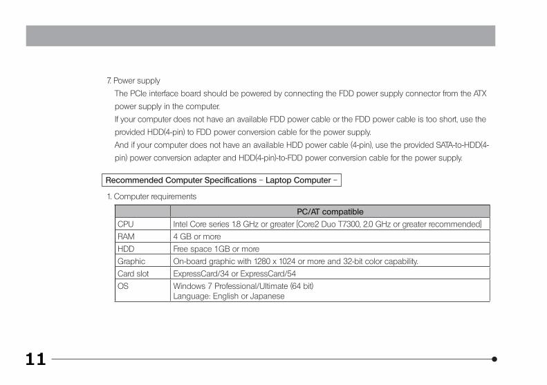
7. Power supply
The PCIe interface board should be powered by connecting the FDD power supply connector from the ATX
power supply in the computer.
If your computer does not have an available FDD power cable or the FDD power cable is too short, use the
provided HDD(4-pin) to FDD power conversion cable for the power supply.
And if your computer does not have an available HDD power cable (4-pin), use the provided SATA-to-HDD(4-
pin) power conversion adapter and HDD(4-pin)-to-FDD power conversion cable for the power supply.
Recommended Computer Specifications – Laptop Computer –
1. Computer requirements
PC/AT compatible
CPU Intel Core series 1.8 GHz or greater [Core2 Duo T7300, 2.0 GHz or greater recommended]
RAM 4 GB or more
HDD Free space 1GB or more
Graphic On-board graphic with 1280 x 1024 or more and 32-bit color capability.
Card slot ExpressCard/34 or ExpressCard/54
OS Windows 7 Professional/Ultimate (64 bit)Language: English or Japanese
12
DP73
2. CPU
We do not guarantee performance if the computer uses a CPU other than or incompatible with Core series or
uses a non-Intel chipset.
3. HDD free space
The HDD free space (the value 1GB or more in Page 9) is the space that does not cause a special problem
when the system is installed or run. The space required for saving an image file in the HDD is slightly more
than 5.6 MB with a 1600 x 1200-pixel (24-bit) non-compressed image and slightly more than 50 MB with a
4800 x 3600-pixel (24-bit) non-compressed image. In consequence, the HDD should also provide a consider-
ably large space for saving these image files.
When saving movies in the HDD stack, the space required for saving a movie is about 80 MB (max.) per
second. The movie recording time is limited according to the HDD free space.
4. RAM
If a RAM other than a PC2700 or greater, dual-channel RAM is used, the full-size live frame rate may drop.
5. Monitor
Us an Adobe RGB compatible monitor when using the camera head in the Adobe RGB mode.
Optimum color reproduction is not available if the sRGB/Adobe RGB setting of the camera head does not
match the setting of the monitor.
6. ExpressCard
The ExpressCard tends to slip out easily from the computer. Be sure not to disconnect the ExpressCard
during operation. For protection from possible damage, do not apply exessive force to the ExpressCard.
Insert or remove the ExpressCard after the PC is shut down.
13
1. This camera head is a precision instrument. Handle it with care and avoid subjecting it to a sudden or severe
impact.
2. The image displayed on the monitor may be affected when it is used at a place close to equipment
generating strong electromagnetic waves. This is not a malfunction and will not affect the actual image being
recorded. To avoid interference during operation, keep the system far from any source of electromagnetic
waves.
3. As the camera head is heavy, hold it carefully not to drop when mounting or storing.
4. Do not use the camera in areas where it may be subjected to direct sunlight, high temperature, humidity,
dust, or vibrations. (For the operating environment conditions, see chapter 8, “SPECIFICATIONS“ on page 35.)
5. Be sure to install the PCIe Extension Unit without blocking the opening for ventilation provided on it.
6. The camera head needs to be calibrated periodically (approx. every 3 months) for the level variations caused
by the influence of cosmic rays. For the calibration method, refer to the CCD Calibration in the online manual
for the cellSens or OLYMPUS Stream software.
7. As a countermeasure against computor virus infection, it is recommended to install an anti-virus software
on the PC. Operation speeds of the cellSens/OLYMPUS Stream may slow down depending on the anti-virus
software.
3 Handling Precautions
14
DP73
1. To clean the lenses and other glass components, simply blow away dirt using a commercially available
blower and wipe gently using a piece of cleaning paper (or clean gauze).
If a lens is stained with fingerprints or oil smudges, wipe it with gauze slightly moistened with commercially
available absolute alcohol.
Since the absolute alcohol is highly flammable, it must be handled carefully. To prevent fire ignition, be
sure to keep it away from open flames or potential sources of electric sparks – for example, electrical
equipment that is being switched on or off.
Also remember to always use these chemicals only in a well-ventilated room.
2. Parts other than the glass components should be cleaned by wiping with a clean cloth. Do not use organic
solvents to remove major stains. Use a soft cloth slightly moistened with a neutral detergent solution.
3. Do not disassemble any part of the camera as this could result in malfunction or reduced performance.
4. When the camera is removed from microscope for storage, be sure to put the C-mount cap included in the
camera, which is necessary to protect the IR cut filter provided inside.
5. When the camera is stored, be sure to keep the C-mount portion downward, since it tends to roll over.
6. When disposing of this product, check your local regulations and rules and be sure to observe them strictly.
CAUTION
4 Maintenance and Storage
15
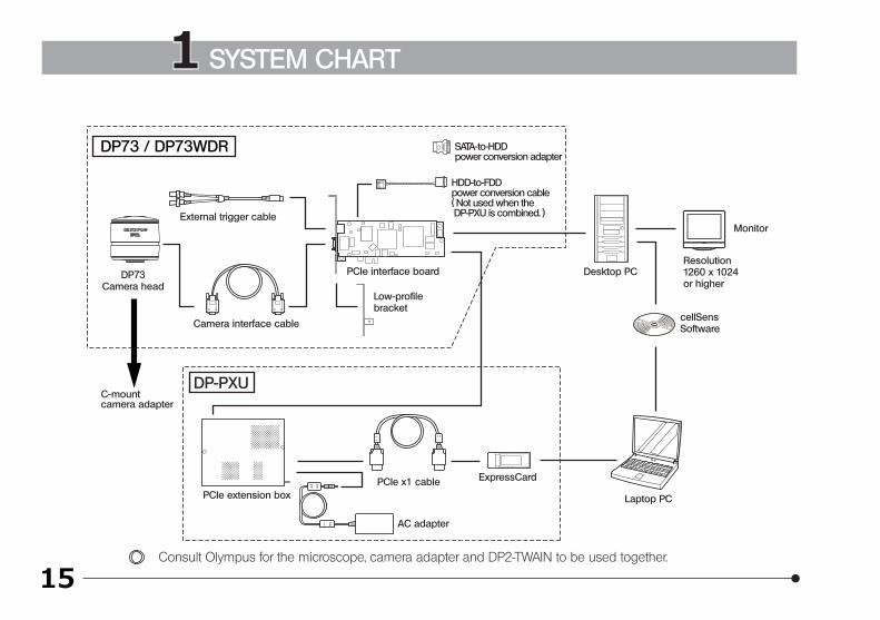
DP73 / DP73WDR
PCIe interface board
Low-profilebracket
HDD-to-FDD power conversion cable( Not used when the DP-PXU is combined. )
DP73Camera head
AC adapter
DP-PXU
PCIe extension boxPCIe x1 cable ExpressCard
Laptop PC
C-mountcamera adapter
External trigger cable
Camera interface cable
Desktop PCResolution1260 x 1024or higher
Monitor
cellSensSoftware
SATA-to-HDD power conversion adapter
Consult Olympus for the microscope, camera adapter and DP2-TWAIN to be used together.
1 SYSTEM CHART
16
DP732 NOMENCLATURE
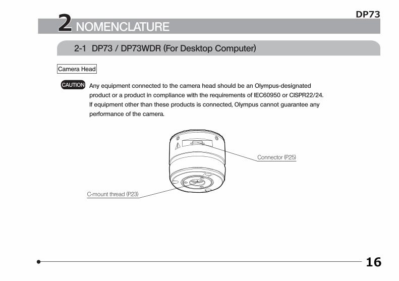
2-1 DP73 / DP73WDR (For Desktop Computer)
Any equipment connected to the camera head should be an Olympus-designated
product or a product in compliance with the requirements of IEC60950 or CISPR22/24.
If equipment other than these products is connected, Olympus cannot guarantee any
performance of the camera.
CAUTION
Camera Head
Connector (P.25)
C-mount thread (P.23)
17
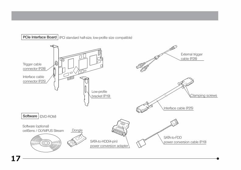
(DVD-ROM)Software
DongleSoftware (optional) cellSens / OLYMPUS Stream
(PCI standard half-size, low-profile size compatible)PCIe Interface Board
External trigger cable (P.28)
Clamping screwsLow-profilebracket (P.19)
Interface cable (P.25)
SATA-to-FDDpower conversion cable (P.19)
Interface cable connector (P.25)
Trigger cable connector (P.28)
SATA-to-HDD(4-pin)power conversion adapter
18
DP73
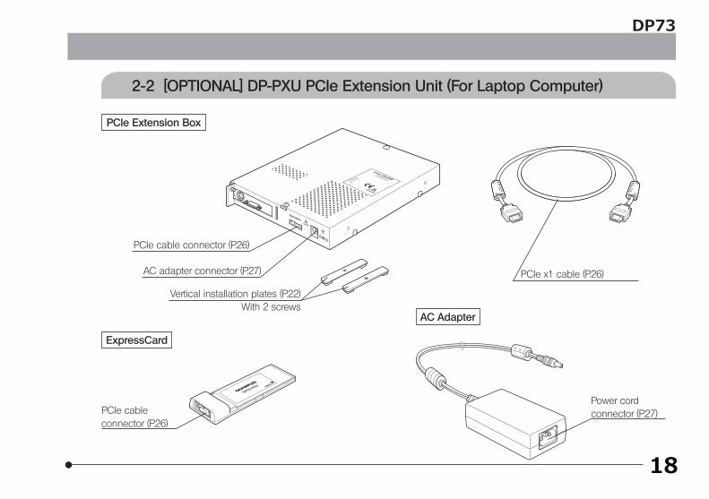
2-2 [OPTIONAL] DP-PXU PCIe Extension Unit (For Laptop Computer)
PCIe Extension Box
PCIe cable connector (P.26)
AC adapter connector (P.27) PCIe x1 cable (P.26)
ExpressCard
AC Adapter
PCIe cable connector (P.26)
Power cord connector (P.27)
Vertical installation plates (P.22) With 2 screws
19
Fig. 1
3 HARDWARE INSTALLATION
a
b
c1
1
2
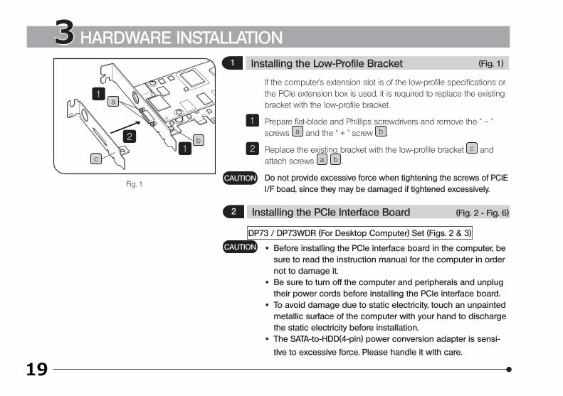
If the computer’s extension slot is of the low-profile specifications or the PCIe extension box is used, it is required to replace the existing bracket with the low-profile bracket.
Prepare flat-blade and Phillips screwdrivers and remove the “ – ” screws a and the “ + ” screw b .
Replace the existing bracket with the low-profile bracket c and attach screws a b .
Do not provide excessive force when tightening the screws of PCIE I/F boad, since they may be damaged if tightened excessively.
1
2
CAUTION
DP73 / DP73WDR (For Desktop Computer) Set (Figs. 2 & 3)
· Before installing the PCIe interface board in the computer, be sure to read the instruction manual for the computer in order not to damage it.
· Be sure to turn off the computer and peripherals and unplug their power cords before installing the PCIe interface board.
· To avoid damage due to static electricity, touch an unpainted metallic surface of the computer with your hand to discharge the static electricity before installation.
· The SATA-to-HDD(4-pin) power conversion adapter is sensi-
tive to excessive force. Please handle it with care.
CAUTION
(Fig. 1)
(Fig. 2 - Fig. 6)
1 Installing the Low-Profile Bracket
2 Installing the PCIe Interface Board
20
Fig. 2
Fig. 3
DP73
1
2
3 4
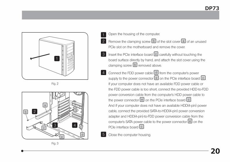
Open the housing of the computer.
Remove the clamping screw b of the slot cover a of an unused
PCIe slot on the motherboard and remove the cover.
Insert the PCIe interface board c carefully without touching the
board surface directly by hand, and attach the slot cover using the
clamping screw b removed above.
Connect the FDD power cable d from the computer’s power
supply to the power connector e on the PCIe interface board c .
If your computer does not have an available FDD power cable or
the FDD power cable is too short, connect the provided HDD-to-FDD
power conversion cable from the computer’s HDD power cable to
the power connector e on the PCIe interface board c .
And if your computer does not have an available HDD(4-pin) power
cable, connect the provided SATA-to-HDD(4-pin) power conversion
adapter and HDD(4-pin)-to-FDD power conversion cable from the
computer’s SATA power cable to the power connector e on the
PCIe interface board c .
Close the computer housing.
1
2
3
4
5
b
c
de
a
21
Fig. 4
2 5
1
3
4b
d
c
e
fa
a
a
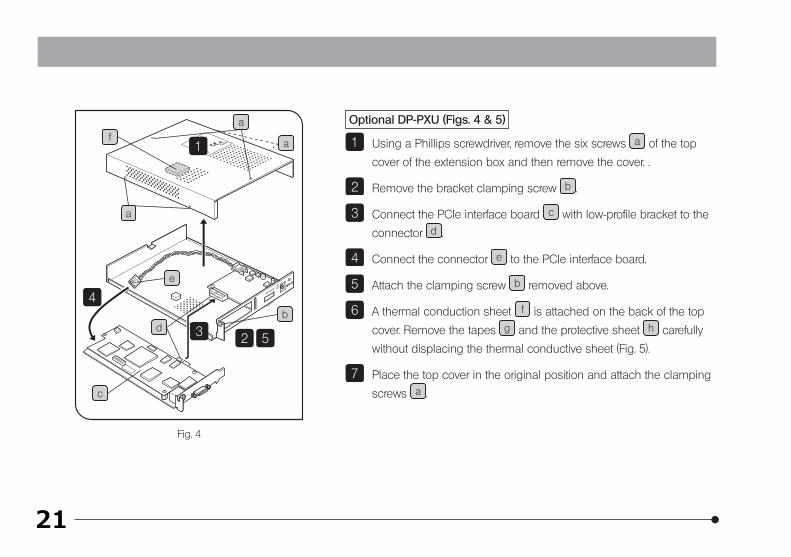
Optional DP-PXU (Figs. 4 & 5)
Using a Phillips screwdriver, remove the six screws a of the top
cover of the extension box and then remove the cover. .
Remove the bracket clamping screw b .
Connect the PCIe interface board c with low-profile bracket to the
connector d .
Connect the connector e to the PCIe interface board.
Attach the clamping screw b removed above.
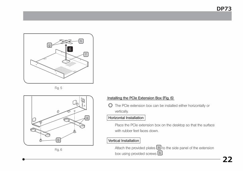
A thermal conduction sheet f is attached on the back of the top
cover. Remove the tapes g and the protective sheet h carefully
without displacing the thermal conductive sheet (Fig. 5).
Place the top cover in the original position and attach the clamping
screws a .
1
2
3
4
5
6
7
22
Fig. 5
Fig. 6
DP73
gh
6f
Installing the PCIe Extension Box (Fig. 6)
The PCIe extension box can be installed either horizontally or
vertically.
Horizontal Installation
Place the PCIe extension box on the desktop so that the surface
with rubber feet faces down.
Vertical Installation
Attach the provided plates a to the side panel of the extension
box using provided screws b .
a
b
23
Fig. 7
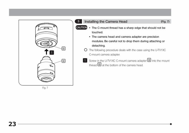
· The C-mount thread has a sharp edge that should not be
touched.
· The camera head and camera adapter are precision
modules. Be careful not to drop them during attaching or
detaching.
The following procedure deals with the case using the U-TV1XC
C-mount camera adapter.
Screw in the U-TV1XC C-mount camera adapter a into the mount
thread b at the bottom of the camera head.
CAUTION
1
1
a
b
(Fig. 7)3 Installing the Camera Head
24
DP73
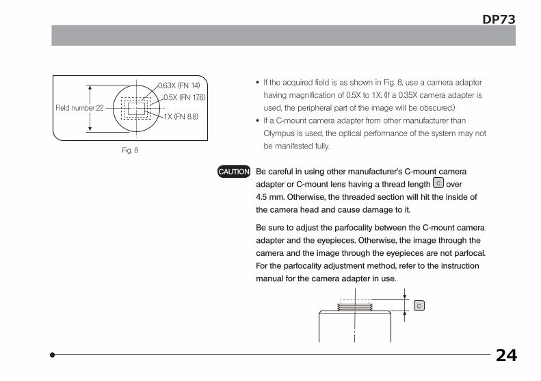
· If the acquired field is as shown in Fig. 8, use a camera adapter
having magnification of 0.5X to 1X. (If a 0.35X camera adapter is
used, the peripheral part of the image will be obscured.)
· If a C-mount camera adapter from other manufacturer than
Olympus is used, the optical performance of the system may not
be manifested fully.
Be careful in using other manufacturer’s C-mount camera
adapter or C-mount lens having a thread length c over
4.5 mm. Otherwise, the threaded section will hit the inside of
the camera head and cause damage to it.
Be sure to adjust the parfocality between the C-mount camera
adapter and the eyepieces. Otherwise, the image through the
camera and the image through the eyepieces are not parfocal.
For the parfocality adjustment method, refer to the instruction
manual for the camera adapter in use.
CAUTION
Fig. 8
0.63X (FN 14)
0.5X (FN 17.6)
1X (FN 8.8)Field number 22
c
25
Fig. 9
Fig. 10
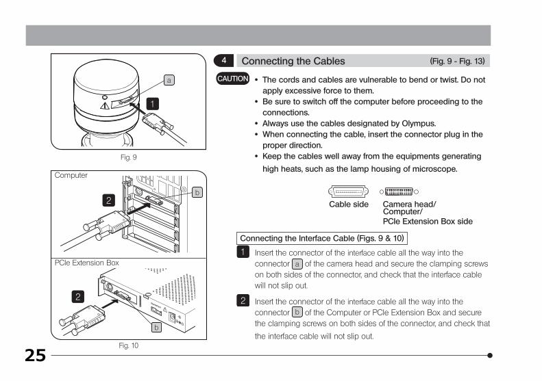
· The cords and cables are vulnerable to bend or twist. Do not apply excessive force to them.
· Be sure to switch off the computer before proceeding to the connections.
· Always use the cables designated by Olympus. · When connecting the cable, insert the connector plug in the
proper direction. · Keep the cables well away from the equipments generating
high heats, such as the lamp housing of microscope.
Cable side Camera head/ Computer/
PCIe Extension Box side
Connecting the Interface Cable (Figs. 9 & 10)
Insert the connector of the interface cable all the way into the connector a of the camera head and secure the clamping screws on both sides of the connector, and check that the interface cable will not slip out.
Insert the connector of the interface cable all the way into the connector b of the Computer or PCIe Extension Box and secure the clamping screws on both sides of the connector, and check that
the interface cable will not slip out.
CAUTION
1
22
1
2
2
b
b
a
Computer
PCIe Extension Box
(Fig. 9 - Fig. 13)4 Connecting the Cables
26
Fig. 11
DP73
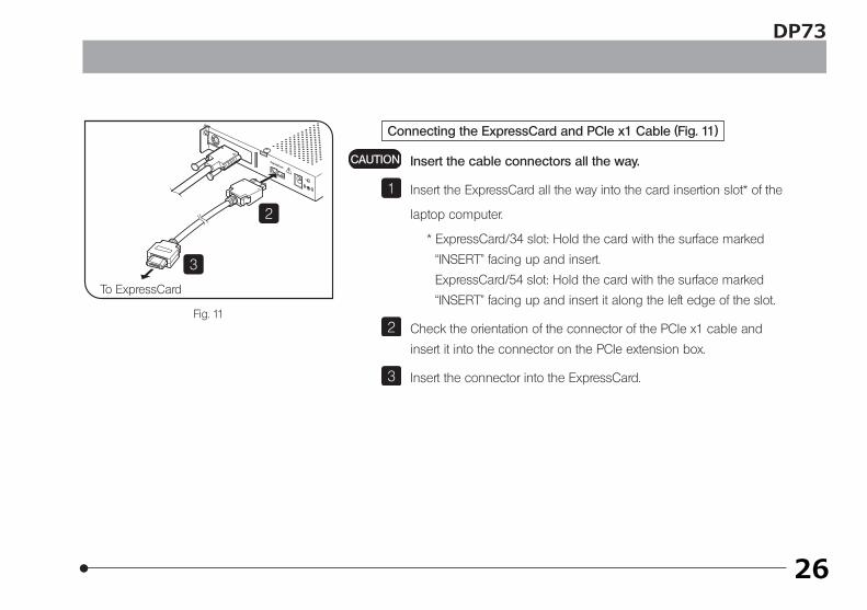
Connecting the ExpressCard and PCIe x1 Cable (Fig. 11)
Insert the cable connectors all the way.
Insert the ExpressCard all the way into the card insertion slot* of the
laptop computer.
* ExpressCard/34 slot: Hold the card with the surface marked
“INSERT” facing up and insert.
ExpressCard/54 slot: Hold the card with the surface marked
“INSERT” facing up and insert it along the left edge of the slot.
Check the orientation of the connector of the PCIe x1 cable and
insert it into the connector on the PCIe extension box.
Insert the connector into the ExpressCard.
CAUTION
1
2
3
2
3
To ExpressCard
27
Fig. 12
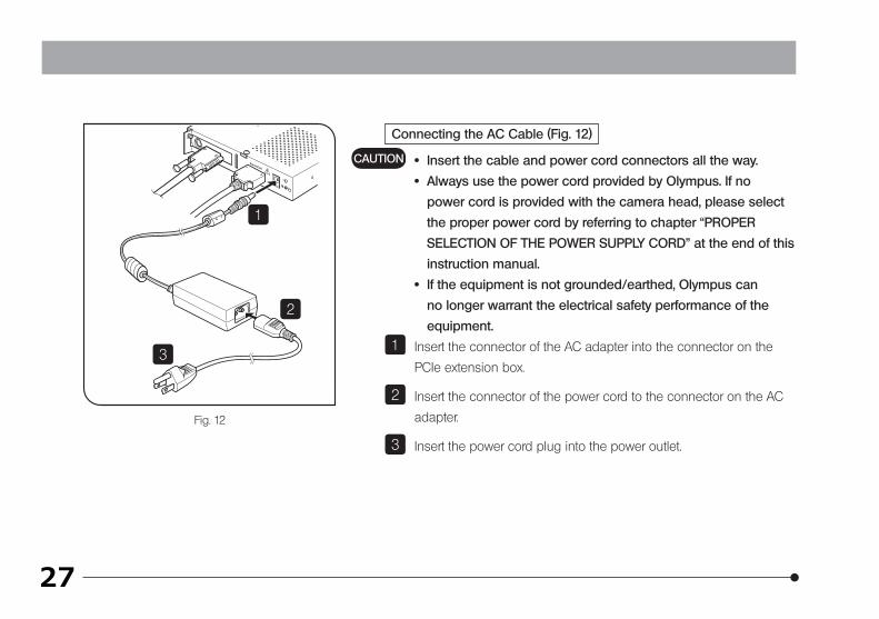
Connecting the AC Cable (Fig. 12)
· Insert the cable and power cord connectors all the way.
· Always use the power cord provided by Olympus. If no
power cord is provided with the camera head, please select
the proper power cord by referring to chapter “PROPER
SELECTION OF THE POWER SUPPLY CORD” at the end of this
instruction manual.
· If the equipment is not grounded/earthed, Olympus can
no longer warrant the electrical safety performance of the
equipment.
Insert the connector of the AC adapter into the connector on the
PCIe extension box.
Insert the connector of the power cord to the connector on the AC
adapter.
Insert the power cord plug into the power outlet.
CAUTION
1
2
3
1
2
3
28
Fig. 13
DP73
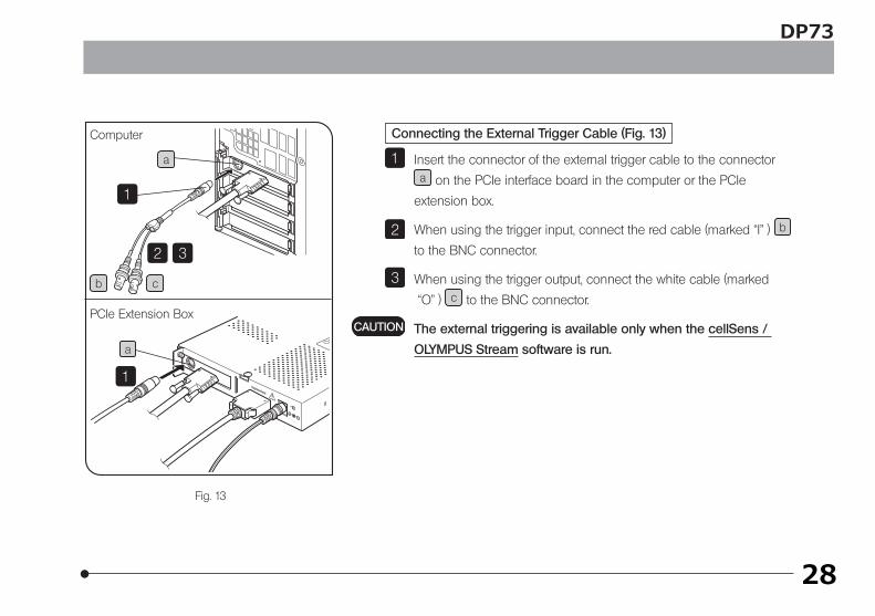
Connecting the External Trigger Cable (Fig. 13)
Insert the connector of the external trigger cable to the connector a on the PCIe interface board in the computer or the PCIe
extension box.
When using the trigger input, connect the red cable (marked “I” ) b to the BNC connector.
When using the trigger output, connect the white cable (marked
“O” ) c to the BNC connector.
The external triggering is available only when the cellSens /
OLYMPUS Stream software is run.
1
2
3
CAUTION
1
1
2 3
Computer
PCIe Extension Box
a
a
b c
29
4 SOFTWARE INSTALLATION
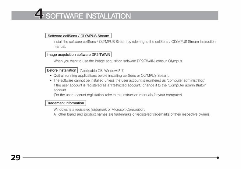
Software cellSens / OLYMPUS Stream
Install the software cellSens / OLYMPUS Stream by referring to the cellSens / OLYMPUS Stream instruction manual.
Image acquisition software DP2-TWAIN
When you want to use the Image acquisition software DP2-TWAIN, consult Olympus.
Before Installation (Applicable OS: Windows® 7) · Quit all running applications before installing cellSens or OLYMPUS Stream. · The software cannot be installed unless the user account is registered as “computer administrator.”
If the user account is registered as a “Restricted account,” change it to the “Computer administrator” account. (For the user account registration, refer to the instruction manuals for your computer.)
Trademark Information
Windows is a registered trademark of Microsoft Corporation.All other brand and product names are trademarks or registered trademarks of their respective owners.

30
DP73
Selection of the devices for DP-PC-S/DP-PC and DP-PCWDR
Refer to the following windows at the selection of devices in the cellSens / OLYMPUS Stream. Device list is
displayed at a time of first start up of the software. Device list can be also displayed by clicking the tabs of
[Acquire], [Devices] and then [Device list] on the Menu bar.
In case DP73 is used In case DP73WDR is used
31
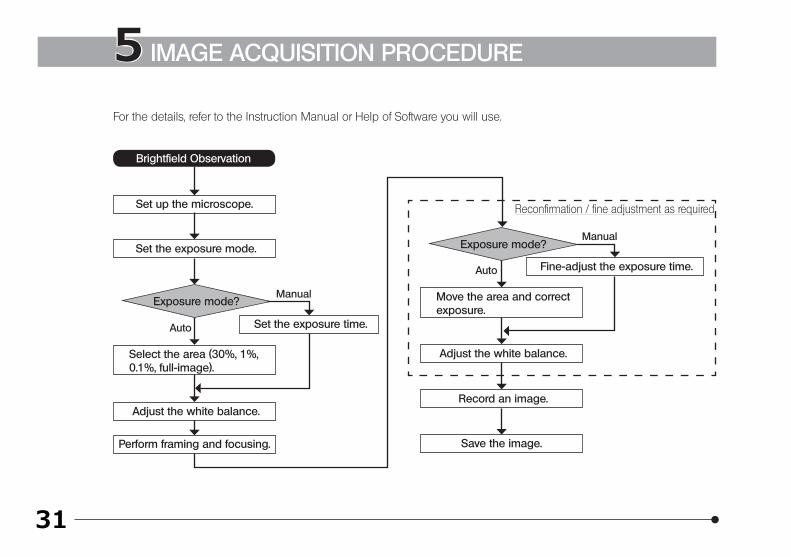
Brightfield Observation
Set up the microscope.
Perform framing and focusing.
Set the exposure mode.
Move the area and correct exposure.
Adjust the white balance.
Record an image.
Select the area (30%, 1%, 0.1%, full-image).
Set the exposure time.
Exposure mode?Manual
Auto
Save the image.
Fine-adjust the exposure time.
Exposure mode?Manual
Auto
For the details, refer to the Instruction Manual or Help of Software you will use.
Adjust the white balance.
Reconfirmation / fine adjustment as required
5 IMAGE ACQUISITION PROCEDURE
32
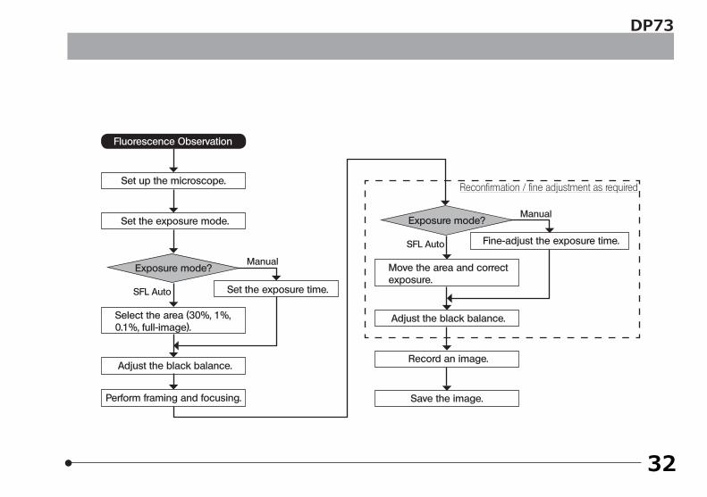
Fluorescence Observation
Set up the microscope.
Perform framing and focusing.
Set the exposure mode.
Move the area and correct exposure.
Adjust the black balance.
Record an image.
Select the area (30%, 1%, 0.1%, full-image).
Set the exposure time.
Exposure mode?Manual
SFL Auto
Save the image.
Fine-adjust the exposure time.
Exposure mode?Manual
SFL Auto
Adjust the black balance.
Reconfirmation / fine adjustment as required
DP73
33
100μsec. or less
Trigger input
Exposure
Readout & transfer to PC
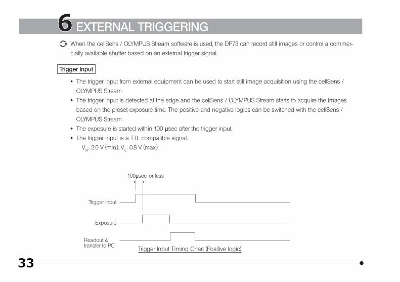
6 EXTERNAL TRIGGERINGWhen the cellSens / OLYMPUS Stream software is used, the DP73 can record still images or control a commer-
cially available shutter based on an external trigger signal.
Trigger Input
· The trigger input from external equipment can be used to start still image acquisition using the cellSens /
OLYMPUS Stream.
· The trigger input is detected at the edge and the cellSens / OLYMPUS Stream starts to acquire the images
based on the preset exposure time. The positive and negative logics can be switched with the cellSens /
OLYMPUS Stream.
· The exposure is started within 100 μsec after the trigger input.
· The trigger input is a TTL compatible signal.
VIH: 2.0 V (min.). VIL: 0.8 V (max.).
Trigger Input Timing Chart (Positive logic)
34
Exposure time lag
Trigger output
Exposure
Readout & transfer to PC
DP73
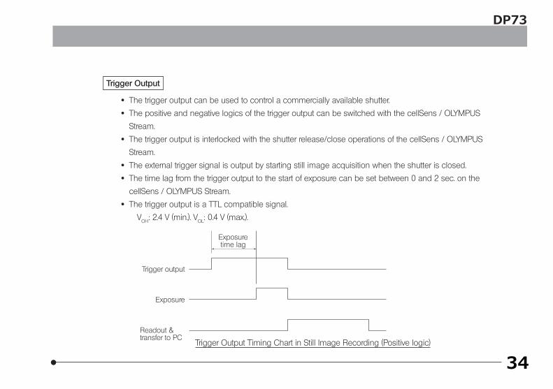
Trigger Output
· The trigger output can be used to control a commercially available shutter.
· The positive and negative logics of the trigger output can be switched with the cellSens / OLYMPUS
Stream.
· The trigger output is interlocked with the shutter release/close operations of the cellSens / OLYMPUS
Stream.
· The external trigger signal is output by starting still image acquisition when the shutter is closed.
· The time lag from the trigger output to the start of exposure can be set between 0 and 2 sec. on the
cellSens / OLYMPUS Stream.
· The trigger output is a TTL compatible signal.
VOH: 2.4 V (min.). VOL: 0.4 V (max.).
Trigger Output Timing Chart in Still Image Recording (Positive logic)
35
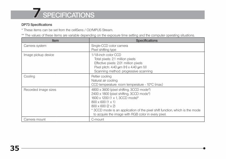
7 SPECIFICATIONSDP73 Specifications
* These items can be set from the cellSens / OLYMPUS Stream.
** The values of these items are variable depending on the exposure time setting and the computer operating situations.
Item Specifications
Camera system Single-CCD color cameraPixel shifting type
Image pickup device 1/1.8-inch color CCD Total pixels: 2.1 million pixels Effective pixels: 2.01 million pixels Pixel pitch: 4.40 μm (H) x 4.40 μm (V) Scanning method: progressive scanning
Cooling Peltier coolingNatural air coolingCCD temperature: room temperature - 10°C (max.)
Recorded image sizes 4800 x 3600 (pixel shifting, 3CCD mode*)2400 x 1800 (pixel shifting, 3CCD mode*)1600 x 1200 (1 x 1, 3CCD mode)*800 x 600 (1 x 1)800 x 600 (2 x 2)* 3CCD mode is an application of the pixel shift function, which is the mode
to acquire the image with RGB color in every pixel.
Camera mount C-mount
36
DP73
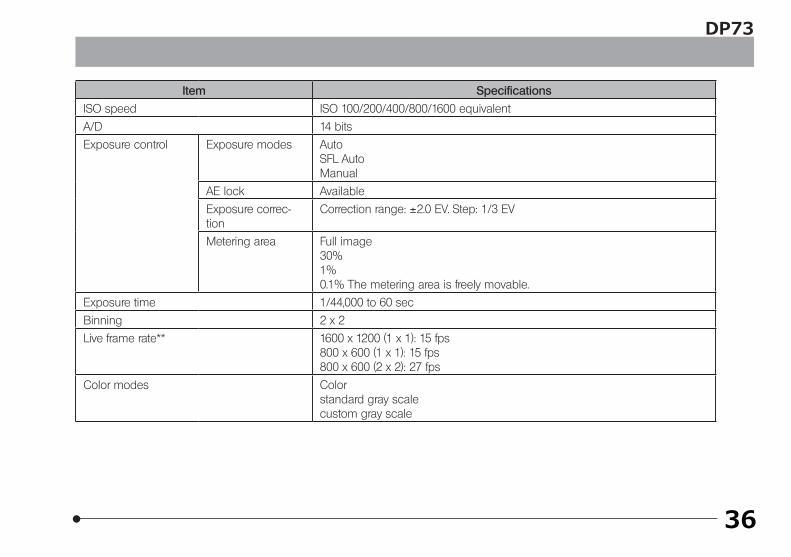
Item Specifications
ISO speed ISO 100/200/400/800/1600 equivalent
A/D 14 bits
Exposure control Exposure modes AutoSFL AutoManual
AE lock Available
Exposure correc-tion
Correction range: ±2.0 EV. Step: 1/3 EV
Metering area Full image30%1%0.1% The metering area is freely movable.
Exposure time 1/44,000 to 60 sec
Binning 2 x 2
Live frame rate** 1600 x 1200 (1 x 1): 15 fps800 x 600 (1 x 1): 15 fps800 x 600 (2 x 2): 27 fps
Color modes Colorstandard gray scalecustom gray scale
37
Item Specifications
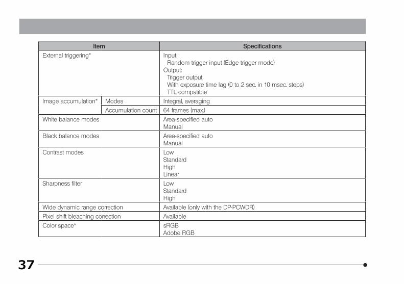
External triggering* Input:Random trigger input (Edge trigger mode)
Output:Trigger outputWith exposure time lag (0 to 2 sec. in 10 msec. steps) TTL compatible
Image accumulation* Modes Integral, averaging
Accumulation count 64 frames (max.)
White balance modes Area-specified autoManual
Black balance modes Area-specified autoManual
Contrast modes LowStandardHighLinear
Sharpness filter LowStandardHigh
Wide dynamic range correction Available (only with the DP-PCWDR)
Pixel shift bleaching correction Available
Color space* sRGBAdobe RGB
38
DP73
Item Specifications
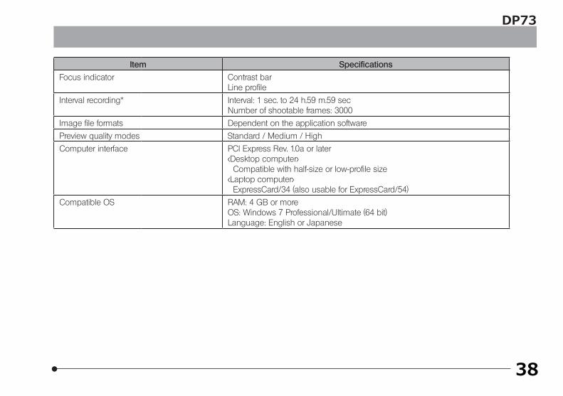
Focus indicator Contrast barLine profile
Interval recording* Interval: 1 sec. to 24 h.59 m.59 secNumber of shootable frames: 3000
Image file formats Dependent on the application software
Preview quality modes Standard / Medium / High
Computer interface PCI Express Rev. 1.0a or later<Desktop computer>
Compatible with half-size or low-profile size<Laptop computer>
ExpressCard/34 (also usable for ExpressCard/54)
Compatible OS RAM: 4 GB or moreOS: Windows 7 Professional/Ultimate (64 bit)Language: English or Japanese
39
Item Specifications
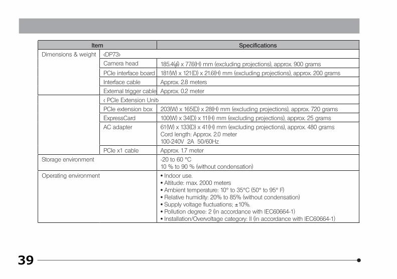
Dimensions & weight <DP73>
Camera head 185.4( ) x 77.6(H) mm (excluding projections), approx. 900 grams
PCIe interface board 181(W) x 121(D) x 21.6(H) mm (excluding projections), approx. 200 grams
Interface cable Approx. 2.8 meters
External trigger cable Approx. 0.2 meter
< PCIe Extension Unit>
PCIe extension box 203(W) x 165(D) x 28(H) mm (excluding projections), approx. 720 grams
ExpressCard 100(W) x 34(D) x 11(H) mm (excluding projections), approx. 25 grams
AC adapter 61(W) x 133(D) x 41(H) mm (excluding projections), approx. 480 gramsCord length: Approx. 2.0 meter100-240V 2A 50/60Hz
PCIe x1 cable Approx. 1.7 meter
Storage environment -20 to 60 °C10 % to 90 % (without condensation)
Operating environment · Indoor use.· Altitude: max. 2000 meters· Ambient temperature: 10° to 35°C (50° to 95° F)· Relative humidity: 20% to 85% (without condensation)· Supply voltage fluctuations; ±10%.· Pollution degree: 2 (in accordance with IEC60664-1)· Installation/Overvoltage category: II (in accordance with IEC60664-1)
40
DP73
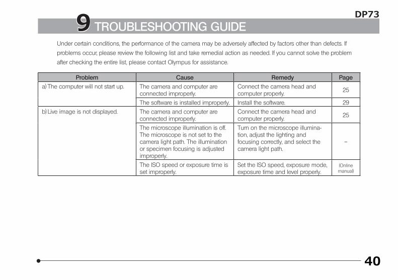
Under certain conditions, the performance of the camera may be adversely affected by factors other than defects. If problems occur, please review the following list and take remedial action as needed. If you cannot solve the problem
after checking the entire list, please contact Olympus for assistance.
Problem Cause Remedy Page
a) The computer will not start up. The camera and computer are connected improperly.
Connect the camera head and computer properly. 25
The software is installed improperly. Install the software. 29
b) Live image is not displayed. The camera and computer are connected improperly.
Connect the camera head and computer properly. 25
The microscope illumination is off. The microscope is not set to the camera light path. The illumination or specimen focusing is adjusted improperly.
Turn on the microscope illumina-tion, adjust the lighting and focusing correctly, and select the camera light path.
–
The ISO speed or exposure time is set improperly.
Set the ISO speed, exposure mode, exposure time and level properly.
(Online manual)
9 TROUBLESHOOTING GUIDE
41
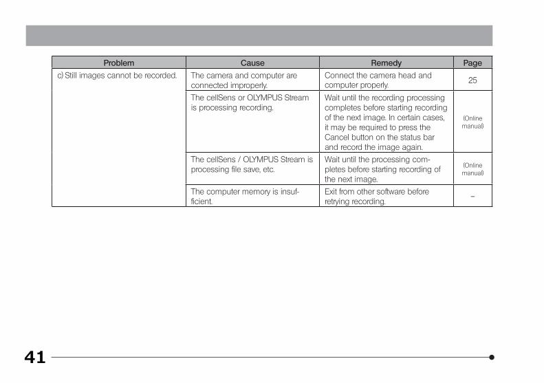
Problem Cause Remedy Page
c) Still images cannot be recorded. The camera and computer are connected improperly.
Connect the camera head and computer properly. 25
The cellSens or OLYMPUS Stream is processing recording.
Wait until the recording processing completes before starting recording of the next image. In certain cases, it may be required to press the Cancel button on the status bar and record the image again.
(Online manual)
The cellSens / OLYMPUS Stream is processing file save, etc.
Wait until the processing com-pletes before starting recording of the next image.
(Online manual)
The computer memory is insuf-ficient.
Exit from other software before retrying recording.
–
42
DP73
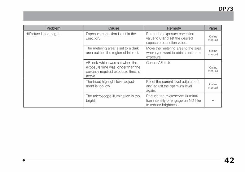
Problem Cause Remedy Page
d) Picture is too bright. Exposure correction is set in the + direction.
Return the exposure correction value to 0 and set the desired exposure correction value.
(Online manual)
The metering area is set to a dark area outside the region of interest.
Move the metering area to the area where you want to obtain optimum exposure.
(Online manual)
AE lock, which was set when the exposure time was longer than the currently required exposure time, is active.
Cancel AE lock.(Online manual)
The input highlight level adjust-ment is too low.
Reset the current level adjustment and adjust the optimum level again.
(Online manual)
The microscope illumination is too bright.
Reduce the microscope illumina-tion intensity or engage an ND filter to reduce brightness.
–
43
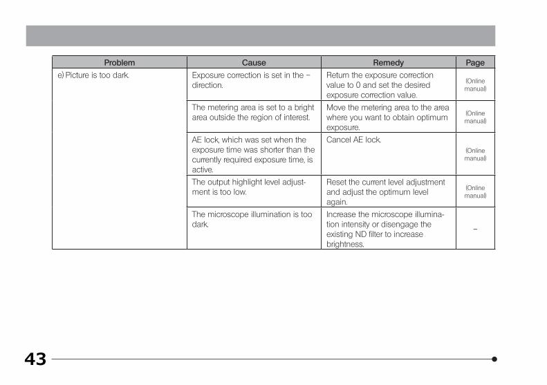
Problem Cause Remedy Page
e) Picture is too dark. Exposure correction is set in the – direction.
Return the exposure correction value to 0 and set the desired exposure correction value.
(Online manual)
The metering area is set to a bright area outside the region of interest.
Move the metering area to the area where you want to obtain optimum exposure.
(Online manual)
AE lock, which was set when the exposure time was shorter than the currently required exposure time, is active.
Cancel AE lock.(Online manual)
The output highlight level adjust-ment is too low.
Reset the current level adjustment and adjust the optimum level again.
(Online manual)
The microscope illumination is too dark.
Increase the microscope illumina-tion intensity or disengage the existing ND filter to increase brightness.
–
44
DP73
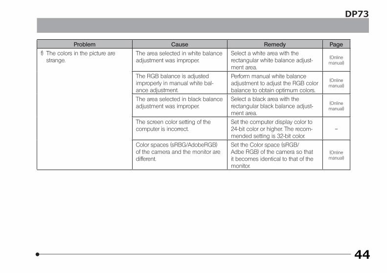
Problem Cause Remedy Page
f) The colors in the picture are strange.
The area selected in white balance adjustment was improper.
Select a white area with the rectangular white balance adjust-ment area.
(Online manual)
The RGB balance is adjusted improperly in manual white bal-ance adjustment.
Perform manual white balance adjustment to adjust the RGB color balance to obtain optimum colors.
(Online manual)
The area selected in black balance adjustment was improper.
Select a black area with the rectangular black balance adjust-ment area.
(Online manual)
The screen color setting of the computer is incorrect.
Set the computer display color to 24-bit color or higher. The recom-mended setting is 32-bit color.
–
Color spaces (sRBG/AdobeRGB) of the camera and the monitor are different.
Set the Color space (sRGB/ Adbe RGB) of the camera so that it becomes identical to that of the monitor.
(Online manual)
45
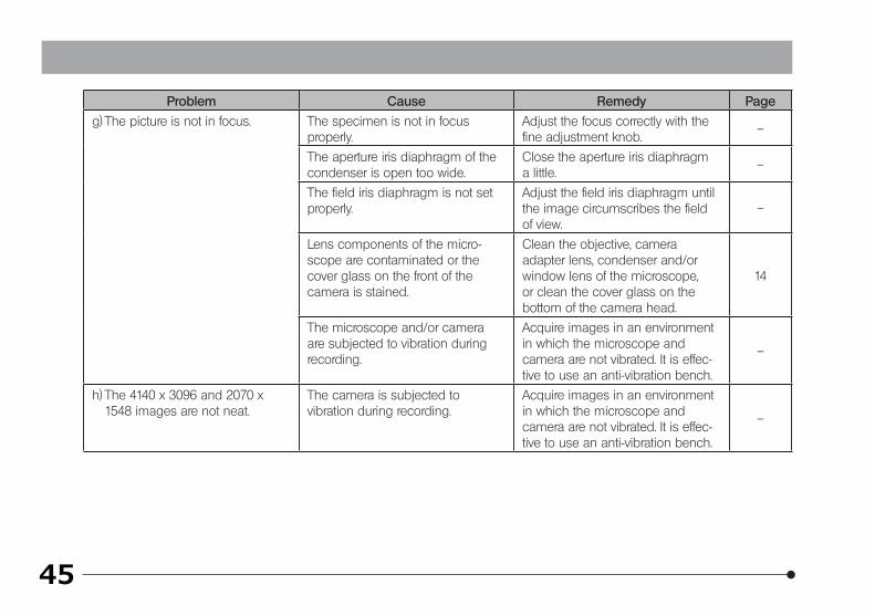
Problem Cause Remedy Page
g) The picture is not in focus. The specimen is not in focus properly.
Adjust the focus correctly with the fine adjustment knob.
–
The aperture iris diaphragm of the condenser is open too wide.
Close the aperture iris diaphragm a little.
–
The field iris diaphragm is not set properly.
Adjust the field iris diaphragm until the image circumscribes the field of view.
–
Lens components of the micro-scope are contaminated or the cover glass on the front of the camera is stained.
Clean the objective, camera adapter lens, condenser and/or window lens of the microscope, or clean the cover glass on the bottom of the camera head.
14
The microscope and/or camera are subjected to vibration during recording.
Acquire images in an environment in which the microscope and camera are not vibrated. It is effec-tive to use an anti-vibration bench.
–
h) The 4140 x 3096 and 2070 x 1548 images are not neat.
The camera is subjected to vibration during recording.
Acquire images in an environment in which the microscope and camera are not vibrated. It is effec-tive to use an anti-vibration bench.
–
46
DP73
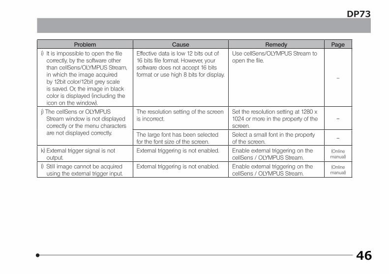
Problem Cause Remedy Page
i) It is impossible to open the file correctly, by the software other than cellSens/OLYMPUS Stream, in which the image acquired by 12bit color/12bit grey scale is saved. Or, the image in black color is displayed (including the icon on the window).
Effective data is low 12 bits out of 16 bits file format. However, your software does not accept 16 bits format or use high 8 bits for display.
Use cellSens/OLYMPUS Stream to open the file.
–
j) The cellSens or OLYMPUS Stream window is not displayed correctly or the menu characters are not displayed correctly.
The resolution setting of the screen is incorrect.
Set the resolution setting at 1280 x 1024 or more in the property of the screen.
–
The large font has been selected for the font size of the screen.
Select a small font in the property of the screen.
–
k) External trigger signal is not output.
External triggering is not enabled. Enable external triggering on the cellSens / OLYMPUS Stream.
(Online manual)
l) Still image cannot be acquired using the external trigger input.
External triggering is not enabled. Enable external triggering on the cellSens / OLYMPUS Stream.
(Online manual)
47
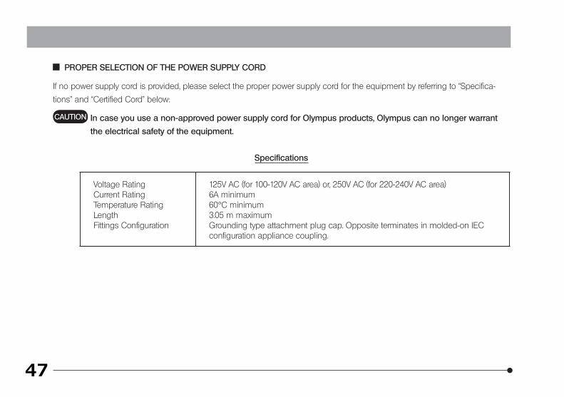
PROPER SELECTION OF THE POWER SUPPLY CORD
If no power supply cord is provided, please select the proper power supply cord for the equipment by referring to “Specifica-
tions” and “Certified Cord” below:
In case you use a non-approved power supply cord for Olympus products, Olympus can no longer warrant
the electrical safety of the equipment.
Specifications
Voltage RatingCurrent RatingTemperature RatingLengthFittings Configuration
125V AC (for 100-120V AC area) or, 250V AC (for 220-240V AC area)6A minimum60°C minimum3.05 m maximumGrounding type attachment plug cap. Opposite terminates in molded-on IEC configuration appliance coupling.
CAUTION
48
DP73
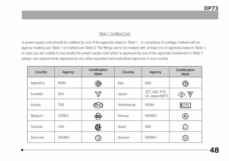
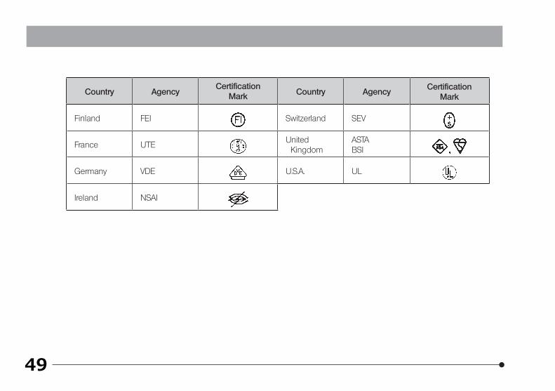
Table 1 Certified Cord
A power supply cord should be certified by one of the agencies listed in Table 1 , or comprised of cordage marked with an
agency marking per Table 1 or marked per Table 2. The fittings are to be marked with at least one of agencies listed in Table 1.
In case you are unable to buy locally the power supply cord which is approved by one of the agencies mentioned in Table 1,
please use replacements approved by any other equivalent and authorized agencies in your country.
Country AgencyCertification
Mark Country AgencyCertification
Mark
Argentina IRAM Italy IMQ
Australia SAA JapanJET, JQA, TÜV,UL Japan/METI
Austria ÖVE Netherlands KEMA
Belgium CEBEC Norway NEMKO
Canada CSA Spain AEE
Denmark DEMKO Sweden SEMKO
49
Country AgencyCertification
Mark Country AgencyCertification
Mark
Finland FEI Switzerland SEV
France UTEUnited Kingdom
ASTABSI
Germany VDE U.S.A. UL
Ireland NSAI
50
DP73
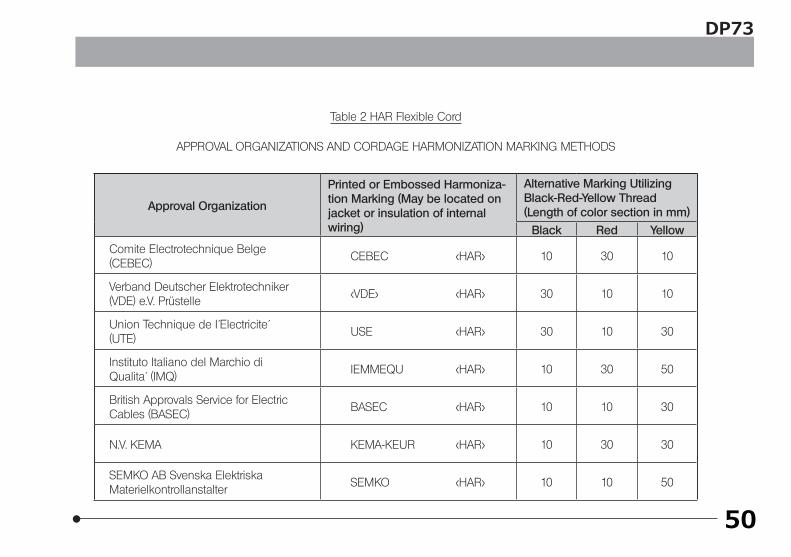
Table 2 HAR Flexible Cord
APPROVAL ORGANIZATIONS AND CORDAGE HARMONIZATION MARKING METHODS
Approval Organization
Printed or Embossed Harmoniza-tion Marking (May be located on jacket or insulation of internal wiring)
Alternative Marking Utilizing Black-Red-Yellow Thread (Length of color section in mm)
Black Red Yellow
Comite Electrotechnique Belge(CEBEC)
CEBEC <HAR> 10 30 10
Verband Deutscher Elektrotechniker(VDE) e.V. Prüstelle
<VDE> <HAR> 30 10 10
Union Technique de I´Electricite´(UTE)
USE <HAR> 30 10 30
Instituto Italiano del Marchio diQualita´ (IMQ)
IEMMEQU <HAR> 10 30 50
British Approvals Service for ElectricCables (BASEC)
BASEC <HAR> 10 10 30
N.V. KEMA KEMA-KEUR <HAR> 10 30 30
SEMKO AB Svenska ElektriskaMaterielkontrollanstalter
SEMKO <HAR> 10 10 50
51
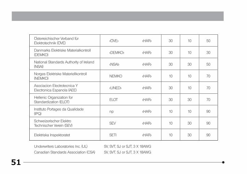
Österreichischer Verband fürElektrotechnik (ÖVE)
<ÖVE> <HAR> 30 10 50
Danmarks Elektriske Materialkontroll(DEMKO)
<DEMKO> <HAR> 30 10 30
National Standards Authority of Ireland (NSAI)
<NSAI> <HAR> 30 30 50
Norges Elektriske Materiellkontroll(NEMKO)
NEMKO <HAR> 10 10 70
Asociacion Electrotecnica YElectronica Espanola (AEE)
<UNED> <HAR> 30 10 70
Hellenic Organization forStandardization (ELOT)
ELOT <HAR> 30 30 70
Instituto Portages da Qualidade(IPQ)
np <HAR> 10 10 90
Schweizerischer ElektroTechnischer Verein (SEV)
SEV <HAR> 10 30 90
Elektriska Inspektoratet SETI <HAR> 10 30 90
Underwriters Laboratories Inc. (UL) SV, SVT, SJ or SJT, 3 X 18AWG
Canadian Standards Association (CSA) SV, SVT, SJ or SJT, 3 X 18AWG

DP73MEMO

MEMO

DP73MEMO

Printed in Japan on October 07, 2011 M 020–02