Embed Size (px)
Citation preview

Microscale combustion & power generationMicroscale combustion & power generation
Jeongmin Ahn, James Kuo, Francisco Ochoa, Lars Sitzki, Jeongmin Ahn, James Kuo, Francisco Ochoa, Lars Sitzki, Craig Eastwood, Paul RonneyCraig Eastwood, Paul Ronney
Dept. of Aerospace & Mechanical EngineeringDept. of Aerospace & Mechanical EngineeringUniv. of Southern California, Los Angeles, CAUniv. of Southern California, Los Angeles, CA
http://ronney.usc.edu/Research/MicroFIREhttp://ronney.usc.edu/Research/MicroFIRE
Supported by DARPA Microsystems Technology Office Supported by DARPA Microsystems Technology Office
and NASA-Glennand NASA-Glenn

• Energy storage density of hydrocarbon fuels (e.g. propane, Energy storage density of hydrocarbon fuels (e.g. propane, 46.4 MJ/kg) >> batteries (≈ 0.5 MJ/kg for Li-ion)46.4 MJ/kg) >> batteries (≈ 0.5 MJ/kg for Li-ion)
• Methanol 2.3x lower, formic acid 8.9x lowerMethanol 2.3x lower, formic acid 8.9x lower• Mesoscale or microscale fuel Mesoscale or microscale fuel electrical power conversion electrical power conversion
device would provide much higher energy/weight than device would provide much higher energy/weight than batteries for low-power applications, even with very low batteries for low-power applications, even with very low efficiencyefficiency
• Problems at micro-scalesProblems at micro-scales• Heat losses to walls - flame quenching, efficiency lossHeat losses to walls - flame quenching, efficiency loss• Friction losses in devices with moving partsFriction losses in devices with moving parts• Precision manufacturing and assembly difficultPrecision manufacturing and assembly difficult
Micro-scale combustion & power generationMicro-scale combustion & power generation
Swiss roll

What is microcombustion?What is microcombustion?
• PDR’s definition: microcombustion occurs in small-PDR’s definition: microcombustion occurs in small-scale flames whose physics is qualitatively different scale flames whose physics is qualitatively different from conventional flames used in macroscopic power from conventional flames used in macroscopic power generation devices, specificallygeneration devices, specifically• The Reynolds numbers is too small for the flow to be The Reynolds numbers is too small for the flow to be
turbulent and thus allow the flame reap the benefits of flame turbulent and thus allow the flame reap the benefits of flame acceleration by turbulence ANDacceleration by turbulence AND
• The flame dimension is too small (i.e. smaller than the The flame dimension is too small (i.e. smaller than the quenching distance, Pe < 40), thus some additional measure quenching distance, Pe < 40), thus some additional measure (heat recirculation, catalytic combustion, reactant (heat recirculation, catalytic combustion, reactant preheating, etc.) is needed to sustain combustionpreheating, etc.) is needed to sustain combustion

• Cox Tee Dee .010 Cox Tee Dee .010 Application: model airplanesApplication: model airplanesWeight: Weight: 0.49 oz.0.49 oz.Bore: Bore: 0.237” = 6.02 mm0.237” = 6.02 mmStroke: Stroke: 0.226” = 5.74 mm0.226” = 5.74 mmDisplacement: 0.00997 cu inDisplacement: 0.00997 cu in
(0.163 cm3)(0.163 cm3)RPM: RPM: 30,00030,000Power:Power: 5 watts5 watts
• Poor performancePoor performance• Low efficiency (4-5%)Low efficiency (4-5%)• Emissions & noise unacceptable for indoor applicationsEmissions & noise unacceptable for indoor applications
• Not “microscale”Not “microscale”• Re = Ud/Re = Ud/ ≈ (2 x 0.6cm x (30000/60s)) (0.6cm) / (0.15 ≈ (2 x 0.6cm x (30000/60s)) (0.6cm) / (0.15
cmcm22/s) = 2400 - high enough for turbulence (barely)/s) = 2400 - high enough for turbulence (barely)• Size > quenching distance even at 1 atm, nowhere near Size > quenching distance even at 1 atm, nowhere near
q.d. at post-compression conditionq.d. at post-compression condition
Smallest existing combustion engineSmallest existing combustion engine

Some power MEMS conceptsSome power MEMS concepts
Wankel rotary engineWankel rotary engine(Berkeley)(Berkeley)QuickTime™ and a
GIF decompressorare needed to see this picture.
Free-piston Free-piston enginesengines(U. Minn,(U. Minn,
Georgia Tech) Georgia Tech)
QuickTime™ and a decompressor
are needed to see this picture.

Some power MEMS concepts - gas turbine (MIT)Some power MEMS concepts - gas turbine (MIT)
• Friction & heat losses • Made from silicon - very
high thermal conductivity - heat transfer along casing heat transfer along casing & rotor, from turbine to & rotor, from turbine to compressorcompressor
• Very high rotational speed (≈ 2 million RPM) needed for compression (speed of sound doesn’t scale!)
• Manufacturing tolerances• Not microscale according Not microscale according
to PDR’s definition: Re ≈ to PDR’s definition: Re ≈ 1000, combustor scale > 1000, combustor scale > quenching distancequenching distance
• Mixing time vs. chemical Mixing time vs. chemical time - mixing time scales time - mixing time scales with combustor size but with combustor size but reaction time does not - reaction time does not - need larger relative need larger relative chamber size as scale chamber size as scale decreases …decreases …

HH22 PEM fuel cells - CWRU - Savinell et al. PEM fuel cells - CWRU - Savinell et al.
• Up to 5 mW/cmUp to 5 mW/cm22 demonstrated demonstrated• Can use borohydride solutions for HCan use borohydride solutions for H22 storage: ≈ 7 mass % H storage: ≈ 7 mass % H22
• NaBHNaBH44 + 2 H + 2 H22O O NaBO NaBO22 + 3 H + 3 H22
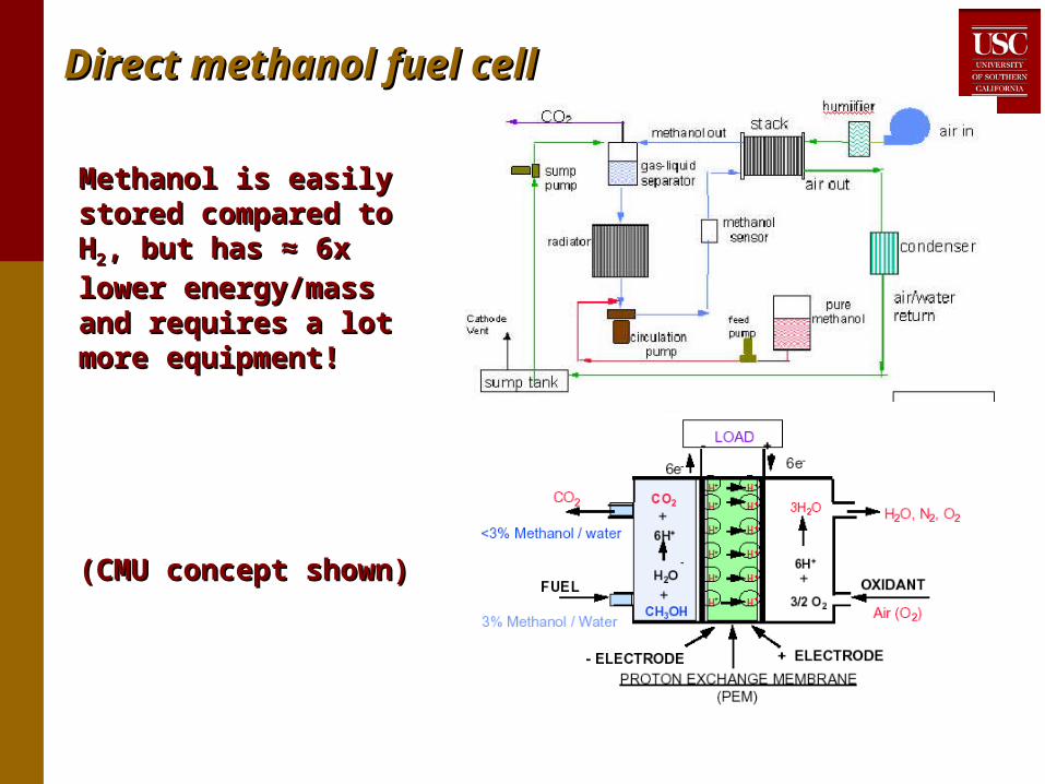
Direct methanol fuel cellDirect methanol fuel cell
Methanol is easily Methanol is easily stored compared to Hstored compared to H22, ,
but has ≈ 6x lower but has ≈ 6x lower energy/mass and energy/mass and requires a lot more requires a lot more equipment!equipment!
(CMU concept shown)(CMU concept shown)

Scaling of micro power generationScaling of micro power generation
• Heat losses vs. heat generationHeat losses vs. heat generation• Heat loss / heat generation ≈ 1/Heat loss / heat generation ≈ 1/ at limit ( at limit ( = non- = non-
dimensional activation energy)dimensional activation energy)• Premixed flames in tubes or channels: PePremixed flames in tubes or channels: PeSSLLd/d/ ≈ 40 - ≈ 40 -
as d as d , need S, need SLL (stronger mixture) to avoid quenching (stronger mixture) to avoid quenching• SSLL = 40 cm/s, = 40 cm/s, = 0.2 cm = 0.2 cm22/s /s quenching distance ≈ 2 mm quenching distance ≈ 2 mm
for stoichiometric HC-airfor stoichiometric HC-air• Note Note ~ P ~ P-1-1, but roughly S, but roughly SLL ~ P ~ P-0-0, thus can use weaker , thus can use weaker
mixture at higher Pmixture at higher P• Also: Pe = 40 assumes cold walls - less quenching Also: Pe = 40 assumes cold walls - less quenching
problem with higher wall temperature (obviouslyproblem with higher wall temperature (obviously))
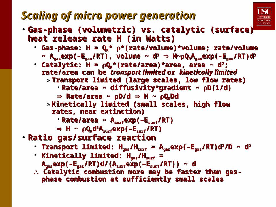
Scaling of micro power generationScaling of micro power generation• Gas-phase (volumetric) vs. catalytic (surface) heat Gas-phase (volumetric) vs. catalytic (surface) heat
release rate H (in Watts)release rate H (in Watts)• Gas-phase: H = QGas-phase: H = QRR* * *(rate/volume)*volume; rate/volume ~ *(rate/volume)*volume; rate/volume ~
AAgasgasexp(–Eexp(–Egasgas/RT), volume ~ d/RT), volume ~ d33 H~ H~QQRRAAgasgasexp(–Eexp(–Egasgas/RT)d/RT)d33
• Catalytic: H = Catalytic: H = QQRR*(rate/area)*area, area ~ d*(rate/area)*area, area ~ d22; rate/area can be ; rate/area can be transport limited transport limited or or kinetically limitedkinetically limited
» Transport limited (large scales, low flow rates)Transport limited (large scales, low flow rates)• Rate/area ~ diffusivity*gradient ~ Rate/area ~ diffusivity*gradient ~ D(1/d) D(1/d) Rate/area ~ Rate/area ~ D/d D/d H ~ H ~ QQRRDd Dd
» Kinetically limited (small scales, high flow rates, near Kinetically limited (small scales, high flow rates, near extinction)extinction)
• Rate/area ~ ARate/area ~ Asurfsurfexp(–Eexp(–Esurfsurf/RT) /RT) H ~ H ~ QQRRdd22AAsurfsurfexp(–Eexp(–Esurfsurf/RT) /RT)
• Ratio gas/surface reactionRatio gas/surface reaction• Transport limited: HTransport limited: Hgasgas/H/Hsurfsurf = A = Agasgasexp(–Eexp(–Egasgas/RT)d/RT)d22/D ~ d/D ~ d22
• Kinetically limited: HKinetically limited: Hgasgas/H/Hsurfsurf = = AAgasgasexp(–Eexp(–Egasgas/RT)d/(A/RT)d/(Asurfsurfexp(–Eexp(–Esurfsurf/RT)) ~ d/RT)) ~ d
Catalytic combustion more may be faster than gas-phase Catalytic combustion more may be faster than gas-phase combustion at sufficiently small scalescombustion at sufficiently small scales

Scaling of micro power generationScaling of micro power generation• Flame quenching revisitedFlame quenching revisited
• Heat loss (by conduction) ~ Heat loss (by conduction) ~ gg(Area)(Area)T/d ~ T/d ~ ggdd22T/d ~ dT/d ~ d• Heat loss / heat generation Heat loss / heat generation
~ d~ d-2-2 (gas-phase combustion) (gas-phase combustion)~ d~ d-1-1 (surface, transport limited) (surface, transport limited)~ d~ d00 (surface, kinetically limited, relevant to (surface, kinetically limited, relevant to
microcombustion)microcombustion)Catalytic combustion may be necessary at small scales Catalytic combustion may be necessary at small scales
to avoid quenching by heat losses!to avoid quenching by heat losses!

Scaling of micro power generationScaling of micro power generation• Turbulence (example: IC engine, bore = stroke = d)Turbulence (example: IC engine, bore = stroke = d)
• Re = URe = Uppd/d/ ≈ (2dN)d/ ≈ (2dN)d/ = 2d = 2d22N/N/UUpp = piston speed; N = engine rotational speed (rev/min) = piston speed; N = engine rotational speed (rev/min)
• Minimum Re ≈ several 1000 for turbulent flowMinimum Re ≈ several 1000 for turbulent flow• Need N ~ 1/dNeed N ~ 1/d22 or U or Upp ~ 1/d to maintain turbulence (!) ~ 1/d to maintain turbulence (!) • Typical auto engine at idle: Re ≈ (2 x (10 cm)Typical auto engine at idle: Re ≈ (2 x (10 cm)22 x (600/60s)) / x (600/60s)) /
(0.15 cm(0.15 cm22/s) = 13000 - high enough for turbulence/s) = 13000 - high enough for turbulence• Cox Tee Dee: Re ≈ (2 x (0.6 cm)Cox Tee Dee: Re ≈ (2 x (0.6 cm)22 x (30000/60s)) / (0.15 cm x (30000/60s)) / (0.15 cm22/s) /s)
= 2400 - high enough for turbulence (barely) (maybe)= 2400 - high enough for turbulence (barely) (maybe)• Why need turbulence? Increase burning rate - but how Why need turbulence? Increase burning rate - but how
much?much?» Turbulent burning velocity (STurbulent burning velocity (STT) ≈ turbulence intensity (u’)) ≈ turbulence intensity (u’)
» u’ ≈ 0.5 Uu’ ≈ 0.5 Upistonpiston (Heywood, 1988) ≈ dN (Heywood, 1988) ≈ dN
» ≈ ≈ 67 cm/s > S67 cm/s > SLL (auto engine at idle, much more at higher (auto engine at idle, much more at higher
N)N)» ≈ ≈ 300 cm/s >> S300 cm/s >> SLL (Cox Tee Dee) (Cox Tee Dee)

Scaling of micro power generationScaling of micro power generation
• Fricton due to fluid flow in piston/cylinder gapFricton due to fluid flow in piston/cylinder gap• Shear stress (Shear stress () = µ) = µoiloil(du/dy) = µ(du/dy) = µoiloilUUpp/h/h• Friction power = Friction power = x area x velocity = 4µ x area x velocity = 4µoiloilUUppLL22/h = /h =
4µ4µoiloilReRe2222/h /h • Thermal power = mass flux x CThermal power = mass flux x Cpp x x TTcombustion combustion = = SSTTdd22CCppT = T = (U(Upp/2)d/2)d22CCppT = T = Re)dCRe)dCppT/2T/2
• Friction power / thermal power = [8µFriction power / thermal power = [8µoiloil(Re)(Re)]/[]/[CCppThd)] ≈ Thd)] ≈ 0.002 for macroscale engine0.002 for macroscale engine
• ImplicationsImplications» Need Re ≥ ReNeed Re ≥ Reminmin to have turbulence to have turbulence» Material properties µMaterial properties µoiloil, , , , CCpp,, T essentially fixedT essentially fixed For geometrically similar engines (h ~ d), importance For geometrically similar engines (h ~ d), importance
of friction losses ~ 1/dof friction losses ~ 1/d22 ! !• What is allowable h? Need to have sufficiently small leakageWhat is allowable h? Need to have sufficiently small leakage
» Simple fluid mechanics: volumetric leak rate = (Simple fluid mechanics: volumetric leak rate = (P)hP)h33/3µ/3µ» Rate of volume sweeping = UdRate of volume sweeping = Ud22 - must be >> leak rate - must be >> leak rate» Need h << (3Need h << (3dRedReminmin//P)P)1/31/3
» Don’t need geometrically similar engine, but still need h ~ Don’t need geometrically similar engine, but still need h ~ dd1/31/3, thus importance of friction loss ~ 1/d, thus importance of friction loss ~ 1/d4/34/3!!

• Three projects at USC Three projects at USC • Thermoelectric power generation (DARPA)Thermoelectric power generation (DARPA)• Single-chamber solid-oxide fuel cell (DARPA)Single-chamber solid-oxide fuel cell (DARPA)• Microscale jet or rocket engine (NASA)Microscale jet or rocket engine (NASA)• Common themesCommon themes
» No moving partsNo moving parts» Use common fuels in airUse common fuels in air» Spiral counterflow heat exchanger / combustor (“Swiss Spiral counterflow heat exchanger / combustor (“Swiss
roll”) for thermal managementroll”) for thermal management» Catalytic combustionCatalytic combustion» Thermal transpiration for pumping of fuel and airThermal transpiration for pumping of fuel and air» Non-traditional fabrication and materialsNon-traditional fabrication and materials
Micro-scale combustion & power generationMicro-scale combustion & power generation

• ““Swiss roll” heat recirculating burner - Swiss roll” heat recirculating burner - minimizes heat losses minimizes heat losses
Toroidal 3D geometry:Toroidal 3D geometry:further reduces losses - further reduces losses - minimizes external temperature minimizes external temperature on all surfaceson all surfaces
Thermal managementThermal management
1D counterflow heat exchanger and combustor
Products
Reactants
Combustion
volume
1600 1200 400 300 K500
1400 600 5007001600
Products
Reactants
Combustion
volume
1600 1200 400 300 K500
1400 600 5007001600
2D “Swiss roll” combustor(Weinberg, 1970’s)

Approach for thermal-fluid designApproach for thermal-fluid design• Test macroscale versions of mesoscale combustorTest macroscale versions of mesoscale combustor• Use experiments to calibrate/verify CFD simulations at Use experiments to calibrate/verify CFD simulations at
various Reynolds number (Re)various Reynolds number (Re)Re Re Uw/ Uw/; U = inlet velocity, w = channel width, ; U = inlet velocity, w = channel width, = viscosity = viscosity
• DemonstrateDemonstrate• Scale down process (macro Scale down process (macro meso or micro) meso or micro)• Ability to model (macro, meso) over a range of ReAbility to model (macro, meso) over a range of Re
• Use CFD models to optimize meso- and micro-scale Use CFD models to optimize meso- and micro-scale devices (difficult to use diagnostics at small scales)devices (difficult to use diagnostics at small scales)
• Key issuesKey issues• Extinction limits, especially at low ReExtinction limits, especially at low Re• Catalytic vs. gas-phase combustionCatalytic vs. gas-phase combustion• Control of temperature, mixture & residence time for Control of temperature, mixture & residence time for
thermoelectric or solid oxide fuel cell generatorthermoelectric or solid oxide fuel cell generator

Swiss roll experimentsSwiss roll experiments• Initial 2-D inconel designs - high thermal conductivity Initial 2-D inconel designs - high thermal conductivity
(poor low-Re performance) & thermal expansion (poor low-Re performance) & thermal expansion coefficient (warpage)coefficient (warpage)
• Titanium - 2x lower conductivity & expansion than inconel, Titanium - 2x lower conductivity & expansion than inconel, improved performanceimproved performance
• Bare metal Pt catalyst in center of burnerBare metal Pt catalyst in center of burner• Implementation of experimentsImplementation of experiments
• 3.5 turn 2-D rectangular Swiss rolls3.5 turn 2-D rectangular Swiss rolls• PC control and data acquisition using LabViewPC control and data acquisition using LabView• Mass flow controllers for fuel Mass flow controllers for fuel (propane)(propane) & air & air• Thermocouples - 1 in each inlet & outlet turn (7 total) Thermocouples - 1 in each inlet & outlet turn (7 total)

Macroscale experimentsMacroscale experiments
Mass Flow
Controllers
Air
PC with LabView
Fuel O2 or N2
Flashback
arrestor
NI-DAQ board
Gas ChromatographPC with PeakSimple
Thermocouples
Outgoing
products
Incoming reactants

Macroscale experimentsMacroscale experiments
1
32
45
67
INLET EXHAUST
CATALYSTPLACEMENT
(Area ≈ 30 cm2)
7 cm
0.35 cm
• 3.5 mm channel width, 0.5 mm wall 3.5 mm channel width, 0.5 mm wall thicknessthickness
• Top & bottom sealed with ceramic blanket Top & bottom sealed with ceramic blanket insulationinsulation

Quenching limitsQuenching limits
0.1
1
10
1 10 100 1000
Eq
uiv
ale
nc
e R
ati
o
Reynolds Number
Out-of-centerreaction zone
(cat. & gas-phase)
Catalytic combustion
only
Nocombustion
Nocombustion
NH3
conditioned catalytic
combustiononly
Catalytic orgas-phasecombustion
3.5 turn macroscale inconel burnerPropane-air mixturesPt catalyst where noted

Quenching limitsQuenching limits• Gas-phase extinction limitsGas-phase extinction limits
• ≈ ≈ symmetrical about symmetrical about = 1 = 1• Minimum Re ≈ 40Minimum Re ≈ 40
• CatalyticCatalytic• Low ReLow Re
» Very low Re (≈ 1) possibleVery low Re (≈ 1) possible» Lean limit rich of stoichiometric (!), limits very asymmetrical Lean limit rich of stoichiometric (!), limits very asymmetrical
about about = 1 - due to need for excess fuel to scrub O = 1 - due to need for excess fuel to scrub O22 from from
catalyst surface (consistent with computations - later…)catalyst surface (consistent with computations - later…)» Conditioning Pt catalyst by burning NHConditioning Pt catalyst by burning NH33 very beneficial, very beneficial,» Rearranging catalyst or 4x increase in area: Rearranging catalyst or 4x increase in area: practically no practically no
effect! - not transport limitedeffect! - not transport limited• Intermediate Re: only slight improvement with catalystIntermediate Re: only slight improvement with catalyst• Still higher Re: no effect of catalystStill higher Re: no effect of catalyst
• Near stoichiometric, higher Re: strong combustion, heat Near stoichiometric, higher Re: strong combustion, heat recirculation not needed, reaction zone not centered, not recirculation not needed, reaction zone not centered, not stable (same result with or without catalyst)stable (same result with or without catalyst)
““Flameless combustion”Flameless combustion”• Combustion usually occurs in “flameless” mode - no visible flame Combustion usually occurs in “flameless” mode - no visible flame
even in darkened room, even without catalysteven in darkened room, even without catalyst• Also seen in highly preheated air combustion (Wünning and Also seen in highly preheated air combustion (Wünning and
Wünning (1997), Katsuki & Hasegawa (1998), Maruta et al (2000))Wünning (1997), Katsuki & Hasegawa (1998), Maruta et al (2000))• Residence times longer than in conventional flameResidence times longer than in conventional flame• Reaction zone broader than conventional flame Reaction zone broader than conventional flame • More like plug-flow reactor (consistent with measured temperatures)More like plug-flow reactor (consistent with measured temperatures)
Out-of-center combustion regimeOut-of-center combustion regime• Near-stoich. mixtures, high Re: heat recirculation not neededNear-stoich. mixtures, high Re: heat recirculation not needed• Blue reaction zone propagates upstream (“flashback”), becomes Blue reaction zone propagates upstream (“flashback”), becomes
conventional flame, unstableconventional flame, unstable• Non-catalytic: flame extinguishes, cannot be re-establishedNon-catalytic: flame extinguishes, cannot be re-established• With catalystWith catalyst
• Reaction can be re-established Reaction can be re-established - catalyst helps flame stabilization and recovery - catalyst helps flame stabilization and recovery from off-nominal operationfrom off-nominal operation
• Pulsating mode Pulsating mode under moderately rich conditions: gas-phase flame flashes under moderately rich conditions: gas-phase flame flashes upstream to inlet, leaves behind ultra-rich mixture that only burns catalytically, upstream to inlet, leaves behind ultra-rich mixture that only burns catalytically, when fresh incoming mixture reaches catalyst, gas-phase flame flashes when fresh incoming mixture reaches catalyst, gas-phase flame flashes upstream again…upstream again…

0
200
400
600
800
1000
1200
1 10
TC1TC2 TC3TC4 TC5TC6 TC7
Mole percent propane in air
Re = 70 Stoichiometric
1
32
45
67
Thermocouple placementsOut-of-center regimeOut-of-center regime• Lean or richLean or rich
• Maximum possible heat recirculation needed to obtain high enough T Maximum possible heat recirculation needed to obtain high enough T for reactionfor reaction
• Flame centeredFlame centered• Near-stoichiometricNear-stoichiometric
• Heat recirculation not needed - flame self-sustainingHeat recirculation not needed - flame self-sustaining• Reaction zone moves toward inletReaction zone moves toward inlet• Center cool due to heat lossesCenter cool due to heat losses

Thermal characteristics - limit temperaturesThermal characteristics - limit temperatures
400
600
800
1000
1200
1400
1 10 100 1000
T_max (lean, non-cat.)T_max (lean, cat.)T_max (rich, cat.)T_max (cat. at non-cat. lean limit)T_max (lean, NH3-treated cat.)T_max (lean, polymer)T_max (rich, polymer)
Reynolds Number
Probable transitionto gas-phase
reaction
3.5 turn macroscale inconel burnerPropane-air mixturesPt catalyst where noted

Thermal characteristics - limit temperaturesThermal characteristics - limit temperatures
• Much lower limit T with catalyst but only slightly leaner mixturesMuch lower limit T with catalyst but only slightly leaner mixtures• For a given mixture and Re supporting gas-phase combustion, For a given mixture and Re supporting gas-phase combustion,
catalyst actually hurts slightly - only helps when gas-phase failscatalyst actually hurts slightly - only helps when gas-phase fails• Limit temperatures ≈ same lean & richLimit temperatures ≈ same lean & rich• Limit temperatures down to 650˚C (non-cat), 125˚C (cat), 75˚C (!) Limit temperatures down to 650˚C (non-cat), 125˚C (cat), 75˚C (!)
(cat, with NH(cat, with NH33 treatment) treatment)• Limit temperatures follow Arrhenius lawLimit temperatures follow Arrhenius law
• Ln(ReLn(Relimitlimit) ~ -Ln(residence time) ~ 1/T) ~ -Ln(residence time) ~ 1/T• Activation energies ≈ 19 kcal/mole (gas-phase), 6.4 kcal/mole Activation energies ≈ 19 kcal/mole (gas-phase), 6.4 kcal/mole
(catalytic)(catalytic)• Proposed mechanismProposed mechanism
• At limit, heat loss ~ heat generationAt limit, heat loss ~ heat generation• Heat loss ~ THeat loss ~ Tmaxmax-T-T∞∞
• Heat generation ~ exp(-E/RTHeat generation ~ exp(-E/RTmaxmax) ~ ) ~ ∞∞UU∞∞AYAYffQQRR
• Limit temperatures approx. ~ ln(ULimit temperatures approx. ~ ln(U∞∞) ~ ln(Re)) ~ ln(Re)

Thermal characteristics - limit temperaturesThermal characteristics - limit temperatures
• Temperatures across central region of combustor very uniform - Temperatures across central region of combustor very uniform - measured maximum T is indicative of true maximum measured maximum T is indicative of true maximum
QuickTime™ and aTIFF (Uncompressed) decompressorare needed to see this picture.
400
500
600
700
800
900
1000
1100
0.012
0.014
0.016
0.018
0.02
0.022
0.024
0.026
0.028
0 50 100 150 200
TC8
TC9
TC10
TC11
TC12
STD/Tavg
Reynolds Number
σ/Tavg
0%C3H8 ,in air
Pt catalyst
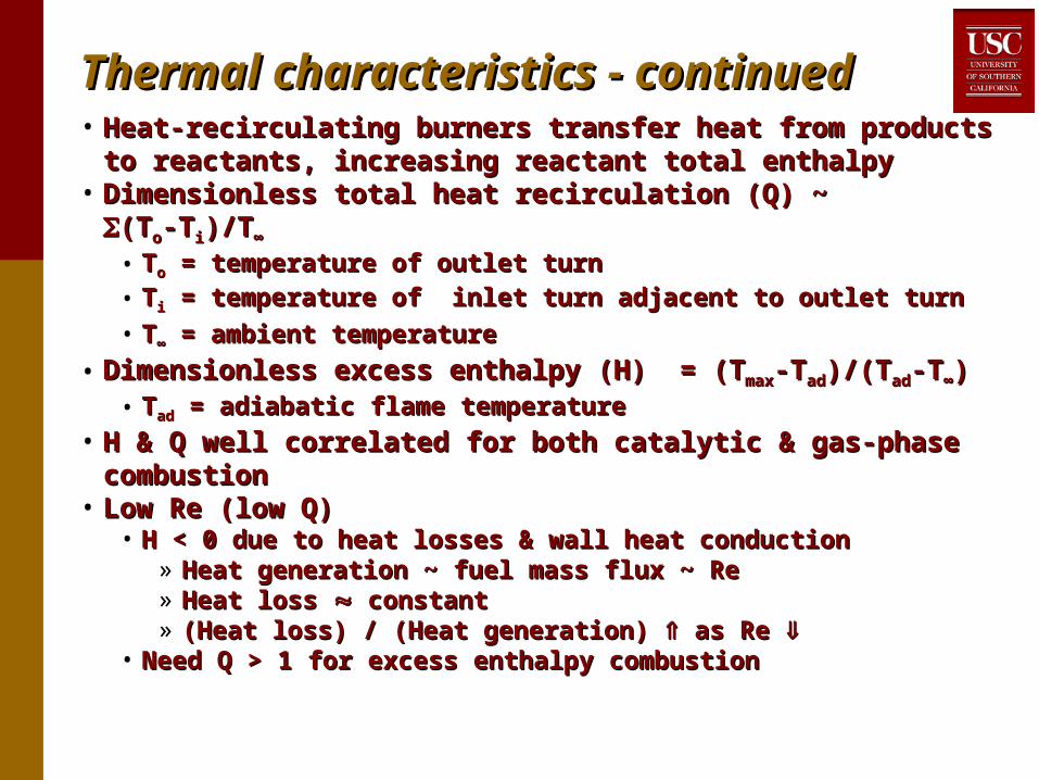
Thermal characteristics - continuedThermal characteristics - continued• Heat-recirculating burners transfer heat from products to Heat-recirculating burners transfer heat from products to
reactants, increasing reactant total enthalpyreactants, increasing reactant total enthalpy• Dimensionless total heat recirculation (Q) ~ Dimensionless total heat recirculation (Q) ~ (T(Too-T-Tii)/T)/T∞∞
• TToo = temperature of outlet turn = temperature of outlet turn• TTii = temperature of inlet turn adjacent to outlet turn = temperature of inlet turn adjacent to outlet turn
• TT∞∞ = ambient temperature = ambient temperature • Dimensionless excess enthalpy (H) = (TDimensionless excess enthalpy (H) = (Tmaxmax-T-Tadad)/(T)/(Tadad-T-T∞∞))
• TTadad = adiabatic flame temperature = adiabatic flame temperature
• H & Q well correlated for both catalytic & gas-phase H & Q well correlated for both catalytic & gas-phase combustioncombustion
• Low Re (low Q)Low Re (low Q)• H < 0 due to heat losses & wall heat conductionH < 0 due to heat losses & wall heat conduction
» Heat generation ~ fuel mass flux ~ ReHeat generation ~ fuel mass flux ~ Re» Heat loss Heat loss constant constant» (Heat loss) / (Heat generation) (Heat loss) / (Heat generation) as Re as Re
• Need Q > 1 for excess enthalpy combustionNeed Q > 1 for excess enthalpy combustion

Thermal characteristics - limit temperaturesThermal characteristics - limit temperatures
-1
-0.5
0
0.5
1
1.5
0 0.5 1 1.5 2 2.5 3 3.5 4
Gas-phaseCatalyticNH
3-treated Catalytic
Heat Transfer Parameter, Q

Exhaust gas compositionExhaust gas composition
Percent (Molar Basis)Re Combustionmode
Catalystarea (cm2) [C3H8]inlet [C3H8] [CO2] [CO] [HC]*
%conv.
Catalytic30 6.26 2.69 10.7 X X 94.4
Catalytic120 6.17 2.40 11.3 X X 97.4
Catalytic30 35.0 33.3 5.21 X X 78.2
10
Catalytic120 35.3 33.6 6.27 X X 86.2
Catalytic30 4.03 0.822 9.63 X X 87.9
16 Catalytic w/NH3 treatment
30 4.08 0.108 11.9 X X99.2
30 3.26 0.420 8.53 X X 87.133 Catalytic120 3.14 0.237 8.70 X X 92.5
30 1.81 0.332 4.44 X X 81.7Catalytic30 7.57 3.66 8.29 2.54 0.520 89.3n/a 1.83 X 5.50 X X 100.0
100Gas-phase
n/a 7.84 3.60 4.02 7.79 0.704 81.0
Catalytic30 10.8 6.64 5.71 3.33 1.75 79.41000
Gas-phase n/a 10.8 6.47 5.92 3.36 2.08 80.6

Exhaust gas compositionExhaust gas composition• All cases: > 80% conversion of scarce reactantAll cases: > 80% conversion of scarce reactant• Low ReLow Re
• No CO or non-propane hydrocarbons found, No CO or non-propane hydrocarbons found, even for ultra-even for ultra-rich mixtures!rich mixtures!
• Only combustion products are COOnly combustion products are CO22 and (probably) H and (probably) H22OO• Additional catalyst has almost no effectAdditional catalyst has almost no effect• NHNH33 catalyst treatment increases fuel conversion catalyst treatment increases fuel conversion
substantially for very low Re cases substantially for very low Re cases • Moderate ReModerate Re
• Some CO formed in rich mixtures, less with catalystSome CO formed in rich mixtures, less with catalyst• High ReHigh Re
• Catalyst ineffective, products same with or without catalystCatalyst ineffective, products same with or without catalyst
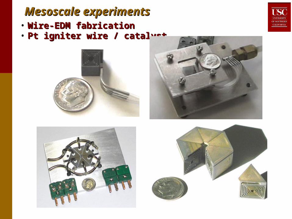
Mesoscale experimentsMesoscale experiments• Wire-EDM fabricationWire-EDM fabrication• Pt igniter wire / catalystPt igniter wire / catalyst
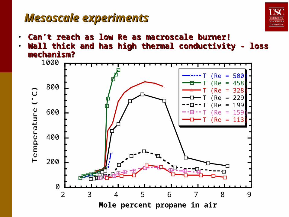
Mesoscale experimentsMesoscale experiments
• Can’t reach as low Re as macroscale burner!Can’t reach as low Re as macroscale burner!• Wall thick and has high thermal conductivity - loss mechanism?Wall thick and has high thermal conductivity - loss mechanism?
0
200
400
600
800
1000
2 3 4 5 6 7 8 9
T (Re = 500)T (Re = 458)T (Re = 328)T (Re = 229)T (Re = 199)T (Re = 159)T (Re = 113)
Mole percent propane in air
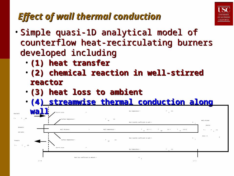
Effect of wall thermal conductionEffect of wall thermal conduction
• Simple quasi-1D analytical model of counterflow Simple quasi-1D analytical model of counterflow heat-recirculating burners developed includingheat-recirculating burners developed including• (1) heat transfer(1) heat transfer• (2) chemical reaction in well-stirred reactor(2) chemical reaction in well-stirred reactor• (3) heat loss to ambient(3) heat loss to ambient• (4) streamwise thermal conduction along wall(4) streamwise thermal conduction along wall
Reactants
T = Ti
(0)
Products
T = Te
(0)
Adiabatic
end walls
Well-stirred
reactor
T = Te
(1)
Area = AR
x = 0 x = 1
Wall temperature = Tw
(x) = ( Tw,e
(x) + Tw
(x))/2
Surface temperature = Tw,e
(x)
Surface temperature = Tw,i
(x)
Heat transfer coefficient to wall = h1
Gas temperature = Te
(x)
Gas temperature = Te
(x)
Heat transfer coefficient to wall = h1
Heat loss coefficient to ambient = h2
Heat loss coefficient to ambient = h2
Wall thickness
Channel height d
Channel height d
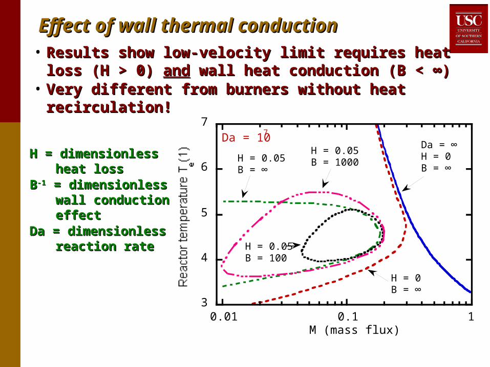
Effect of wall thermal conductionEffect of wall thermal conduction• Results show low-velocity limit requires heat loss (H > 0) Results show low-velocity limit requires heat loss (H > 0)
andand wall heat conduction (B < ∞) wall heat conduction (B < ∞)• Very different from burners without heat recirculation! Very different from burners without heat recirculation!
H = dimensionless H = dimensionless heat lossheat loss
BB-1-1 = dimensionless = dimensionless wall conduction wall conduction effecteffect
Da = dimensionless Da = dimensionless reaction ratereaction rate
3
4
5
6
7
0.01 0.1 1M (mass flux)
Da = ∞H = 0B = ∞
H = 0.05B = 1000
H = 0B = ∞
H = 0.05B = 100
H = 0.05B = ∞
Da = 107

Effect of wall thermal conductionEffect of wall thermal conduction• High-velocity limit almost unaffected by wall conduction, but High-velocity limit almost unaffected by wall conduction, but
low-velocity limit dominated by wall conductionlow-velocity limit dominated by wall conduction• Thin wall, low thermal conductivity material (ceramic vs. Thin wall, low thermal conductivity material (ceramic vs.
steel) will maximize performancesteel) will maximize performance
1
1.1
1.2
1.3
1.4
1.5
1.6
0.001 0.01 0.1M (mass flux)
B = 100
B = 1000
B = 10000
B = ∞

Effect of wall thermal conductionEffect of wall thermal conduction• Predictions consistent with experiments in 2D Swiss Predictions consistent with experiments in 2D Swiss
roll combustors made of inconel (k = 11 W/mK) vs. roll combustors made of inconel (k = 11 W/mK) vs. titanium (k = 7 W/mK) - higher T, wider extinction limits titanium (k = 7 W/mK) - higher T, wider extinction limits with lower kwith lower k
0
200
400
600
800
2 4 6 8 10 30 50
TC1 (Inconel)TC3 (Inconel)TC5 (Inconel)TC1 (Titanium)TC3 (Titanium)TC5 (Titanium)
Mole percent propane in air
Re = 23

Polymer combustorsPolymer combustors
• Experimental and theoretical studies show importance of wall Experimental and theoretical studies show importance of wall thermal conductivity on combustor performance - thermal conductivity on combustor performance - counterintuitive: lower is better - heat transfer across thin wall counterintuitive: lower is better - heat transfer across thin wall is easy, but need to minimize streamwise conductionis easy, but need to minimize streamwise conduction
• Low TLow Tmaxmax demonstrated in metal burners with catalytic demonstrated in metal burners with catalytic
combustion - no need for high-temperature metals (high k) or combustion - no need for high-temperature metals (high k) or ceramics (k = 1 - 2 W/m˚C but fragile, hard to fabricate)ceramics (k = 1 - 2 W/m˚C but fragile, hard to fabricate)
• Use polymers???Use polymers???• Low k (0.3 - 0.4 W/m˚C)Low k (0.3 - 0.4 W/m˚C)• Polyimides, polyetheretherketones, etc., rated to T ≈ 400˚C, even in Polyimides, polyetheretherketones, etc., rated to T ≈ 400˚C, even in
oxidizing atmosphereoxidizing atmosphere• Easy to fabricate, not brittleEasy to fabricate, not brittle
• Key issuesKey issues• SurvivabilitySurvivability• Extinction limits - how lean or rich can we burn?Extinction limits - how lean or rich can we burn?• Control of temperature, mixture & residence time for thermoelectric Control of temperature, mixture & residence time for thermoelectric
or solid oxide fuel cell generatoror solid oxide fuel cell generator

Plastic combustor - implementationPlastic combustor - implementation• World’s first all polymer combustor?World’s first all polymer combustor?• DuPont Vespel SP-1 polyimide (k = 0.29 W/m˚C)DuPont Vespel SP-1 polyimide (k = 0.29 W/m˚C)• CNC milling: 3.5 turn Swiss roll, 3 mm channel width, 0.5 CNC milling: 3.5 turn Swiss roll, 3 mm channel width, 0.5
mm wall thickness, 2.5 cm tallmm wall thickness, 2.5 cm tall• NHNH33-treated bare metal Pt catalyst in central region-treated bare metal Pt catalyst in central region• General performanceGeneral performance
• Prolonged exposure at > 400˚C Prolonged exposure at > 400˚C (high enough for single chamber (high enough for single chamber SOFCs)SOFCs) with no apparent damage with no apparent damage
• Thermal expansion coefficient of Vespel ≈ 4x higher than inconel, Thermal expansion coefficient of Vespel ≈ 4x higher than inconel, but no apparent warpingbut no apparent warping
• Sustained combustion at 2.9 W thermal (birthday candle ≈ 50 W)Sustained combustion at 2.9 W thermal (birthday candle ≈ 50 W)
CatalystCatalystregionregion
5.5 cm
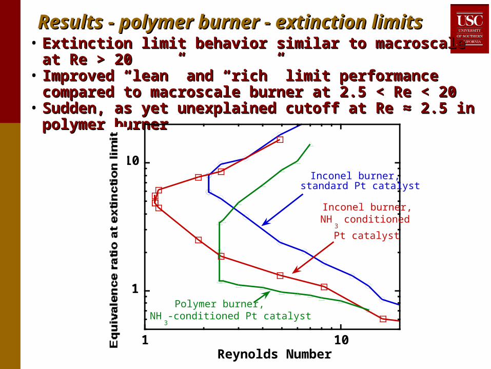
Results - polymer burner - extinction limitsResults - polymer burner - extinction limits• Extinction limit behavior similar to macroscale at Re > 20Extinction limit behavior similar to macroscale at Re > 20• Improved “lean” and “rich” limit performance compared to Improved “lean” and “rich” limit performance compared to
macroscale burner at 2.5 < Re < 20macroscale burner at 2.5 < Re < 20• Sudden, as yet unexplained cutoff at Re ≈ 2.5 in polymer Sudden, as yet unexplained cutoff at Re ≈ 2.5 in polymer
burnerburner
1
10
1 10Reynolds Number
Inconel burner,standard Pt catalyst
Polymer burner,NH
3-conditioned Pt catalyst
Inconel burner,NH
3 conditioned
Pt catalyst
Results - polymer burner - temperaturesResults - polymer burner - temperatures• Sustained combustion at TSustained combustion at Tmaxmax = 72˚C = 72˚C (lowest T ever self-(lowest T ever self-
sustaining hydrocarbon combustion?)sustaining hydrocarbon combustion?)• If combustion can be If combustion can be sustainedsustained at 72˚C, with improved at 72˚C, with improved
thermal management, could room temperature thermal management, could room temperature ignitionignition be be possible?possible?
• Peak T at equivalence ratio ≈ 1.5 for all Re Peak T at equivalence ratio ≈ 1.5 for all Re • Minimum T required to sustain combustion exceeds material Minimum T required to sustain combustion exceeds material
limit at Re > 20, even with catalyst - polymers not suitable for limit at Re > 20, even with catalyst - polymers not suitable for high Rehigh Re
• Low outer wall temperature (≈ 50˚C) even with 400˚C internal Low outer wall temperature (≈ 50˚C) even with 400˚C internal TT

Maximum temperatures - plastic combustorMaximum temperatures - plastic combustor
0
50
100
150
200
250
300
350
400
450
0 5 10 15 20 25 30 35 40
Mole percent fuel in air
Maximum temperature (˚C)
Re = 14
Re = 10
Re = 8
Re = 6
Re = 4
Re = 3
Re = 2.5
Stoichiometric
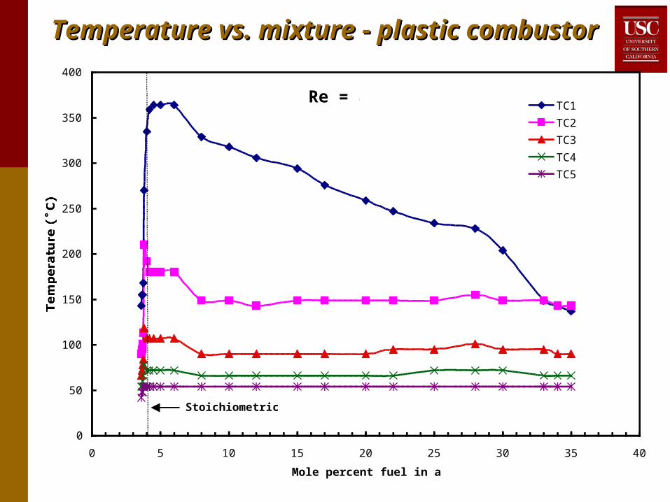
Temperature vs. mixture - plastic combustorTemperature vs. mixture - plastic combustor
0
50
100
150
200
250
300
350
400
0 5 10 15 20 25 30 35 40
Mole percent fuel in air
Temperature (˚C)
TC1
TC2
TC3
TC4
TC5
Stoichiometric
Re = 8

Numerical modelNumerical model
• FLUENT, 2D, 2nd order upwind (3D in work)FLUENT, 2D, 2nd order upwind (3D in work)• 32,000 cells, grid independence verified32,000 cells, grid independence verified• Conduction (solid & gas), convection (gas), Conduction (solid & gas), convection (gas),
radiation (solid-solid only, radiation (solid-solid only, DO method, DO method, = 0.35 = 0.35))• Steady, no turbulence model - valid only at low ReSteady, no turbulence model - valid only at low Re• 1-step chemistry (Westbrook & Dryer), pre-1-step chemistry (Westbrook & Dryer), pre-
exponential adjusted for agreement between model exponential adjusted for agreement between model & expt. at Re = 500& expt. at Re = 500
• All gas & solid properties chosen to simulate All gas & solid properties chosen to simulate inconel burner experimentsinconel burner experiments
• Boundary conditions:Boundary conditions:• Inlet: 300K, plug flowInlet: 300K, plug flow• Outlet: pressure outletOutlet: pressure outlet• Heat loss at boundaries + volumetric term to simulate heat Heat loss at boundaries + volumetric term to simulate heat
loss in 3rd dimension loss in 3rd dimension

inletinlet outletoutlet
Numerical modelNumerical model
12
34
56
7
d
Thermocouple locations
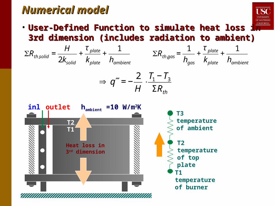
• User-Defined Function to simulate heat loss in 3rd User-Defined Function to simulate heat loss in 3rd dimension (includes radiation to ambient)dimension (includes radiation to ambient)
T1 temperatureof burner
T2temperatureof top plate
T3temperatureof ambient€
⇒ ′′′q = −2
H⋅
T1 − T3
ΣRth€
Rth,solid =H
2ksolid
+τ plate
kplate
+1
hambient
€
Rth,gas =1
hgas
+τ plate
kplate
+1
hambient
inlet outlet
Heat loss in3rd dimension
hambient =10 W/m2KT3
T2T1
H
Numerical modelNumerical model
Results - full modelResults - full model
0
1
2
3
4
10 100 1000
Full modelExperiment
Reynolds number
Anchor point
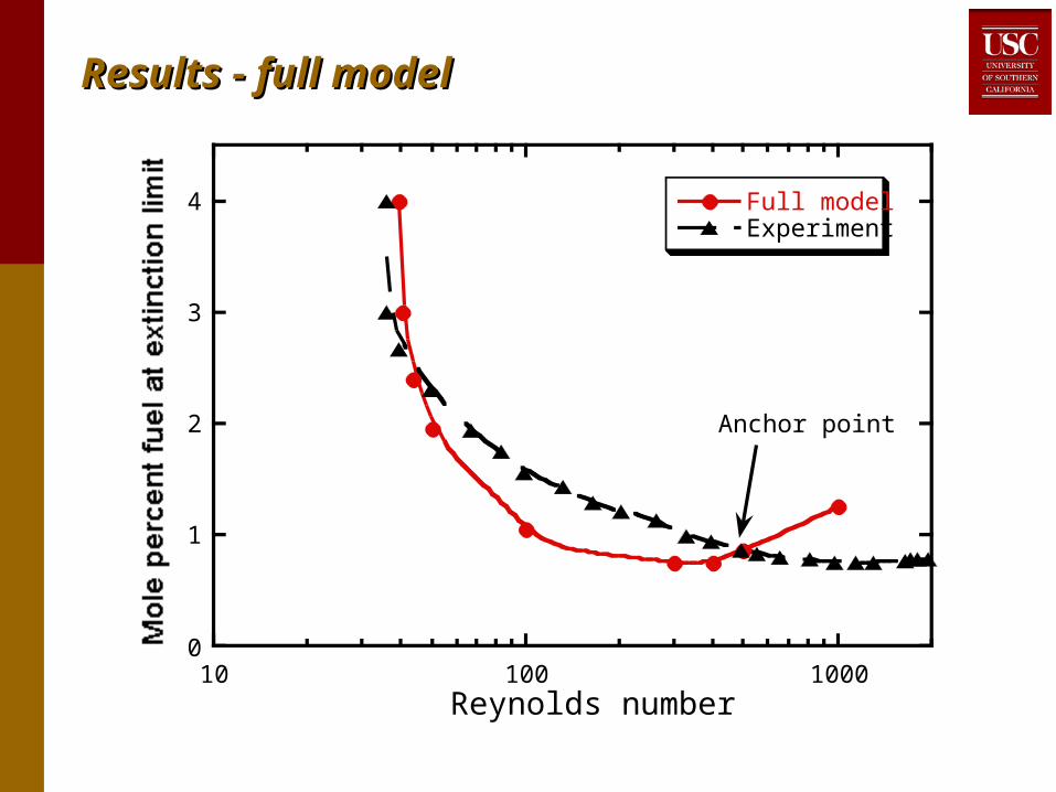
Results - full model - extinction limitsResults - full model - extinction limits• Reasonable agreement between model and experiment Reasonable agreement between model and experiment
for all Refor all Re• High velocity “blow-off” limit-insufficient residence time High velocity “blow-off” limit-insufficient residence time
compared to chemical time scalecompared to chemical time scale• Low velocity heat loss induced limitLow velocity heat loss induced limit• Model & experiment show low-velocity limit at Re ≈ 40, Model & experiment show low-velocity limit at Re ≈ 40,
even for stoichiometric mixtureseven for stoichiometric mixtures• Up-swing in predicted limit composition at high Re not Up-swing in predicted limit composition at high Re not
seen in experimentseen in experiment• Probably due to transition to turbulence (not modeled)Probably due to transition to turbulence (not modeled)• Higher effective conductivity (kHigher effective conductivity (ktt ~ u’ ~ U ~ Re) for turbulent ~ u’ ~ U ~ Re) for turbulent
flow vs. k = constant for laminarflow vs. k = constant for laminar• Leads to greater heat recirculation for turbulent flows, Leads to greater heat recirculation for turbulent flows,
higher temperatures, leaner extinction limitshigher temperatures, leaner extinction limits

Results - full modelResults - full model
800
1000
1200
1400
1600
1800
100 1000
Experiment
Full model
Reynolds number

Results - full model - temperaturesResults - full model - temperatures• ““Virtual thermocouples” - 1 mm x 1 mm region at same Virtual thermocouples” - 1 mm x 1 mm region at same
locations at thermocouples in experimentslocations at thermocouples in experiments• Maximum temperatures at limit higher for 1-step model Maximum temperatures at limit higher for 1-step model
than experiments - typical result for 1-step model than experiments - typical result for 1-step model without chain branching stepswithout chain branching steps
• Higher T over-emphasizes radiative effects (≈ 5x at low Higher T over-emphasizes radiative effects (≈ 5x at low Re)Re)

Results - lower wall thermal conductivityResults - lower wall thermal conductivity• Lower wall conductivity drastically widens limits, but Lower wall conductivity drastically widens limits, but
optimal conductivity is lower than air!optimal conductivity is lower than air!
0.4
0.6
0.8
1
1.2
1.4
1.6
1.8
2
10-4 10-3 10-2 10-1 100 101
Thermal conductivity at room temperature (W/m-K)
Full modelRe = 50
InconelTi
CeramicsPlastics
AirAerogel

Modeling - effect of heat loss & radiationModeling - effect of heat loss & radiation
0
1
2
3
4
10 100 1000
Full modelNo heat lossNo radiationExperiment
Reynolds number

Effect of heat loss & radiationEffect of heat loss & radiation
• Radiation: effect similar to heat lossRadiation: effect similar to heat loss• Causes heat to be conducted along the walls and Causes heat to be conducted along the walls and
subsequently lost to ambient subsequently lost to ambient • Less important at smaller scalesLess important at smaller scales
» Conduction ~ k(Conduction ~ k(T/T/x)x)» Radiation ~ Radiation ~ σσ(T(T44-T-T
44))» Radiation/Conduction ~ Radiation/Conduction ~ xx
• … … but unless you include radiation, you get the wrong but unless you include radiation, you get the wrong answer when you calibrate a macroscale model then apply it answer when you calibrate a macroscale model then apply it to microscales!to microscales!
• High Re: convection dominates heat transfer, finite High Re: convection dominates heat transfer, finite residence time dominates extinction, all models yield residence time dominates extinction, all models yield almost same predictionsalmost same predictions
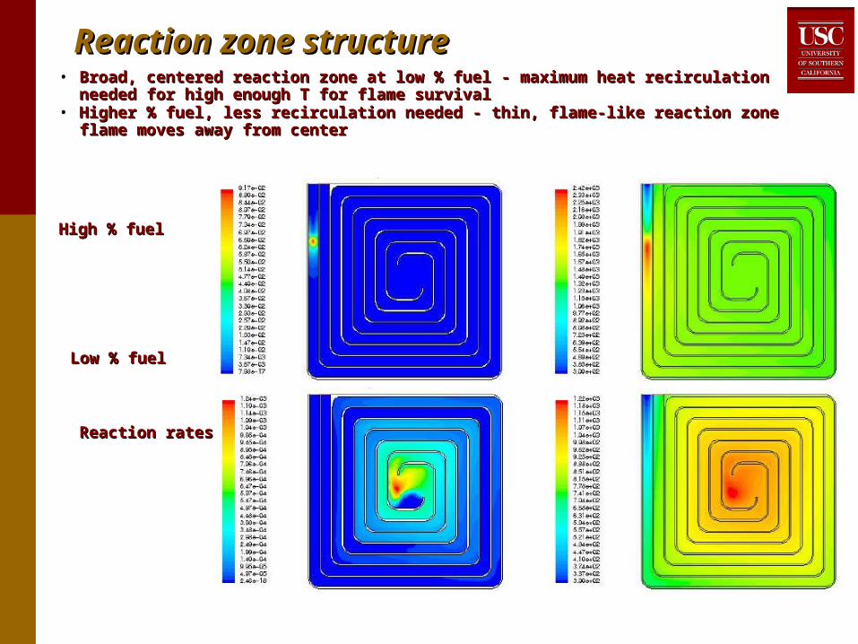
Reaction zone structureReaction zone structure• Broad, centered reaction zone at low % fuel - maximum heat recirculation needed for high Broad, centered reaction zone at low % fuel - maximum heat recirculation needed for high
enough T for flame survivalenough T for flame survival• Higher % fuel, less recirculation needed - thin, flame-like reaction zone flame moves away Higher % fuel, less recirculation needed - thin, flame-like reaction zone flame moves away
from centerfrom center
High % fuelHigh % fuel
Low % fuelLow % fuel
Reaction rates Reaction rates Temperatures Temperatures
Reaction rate Temperature
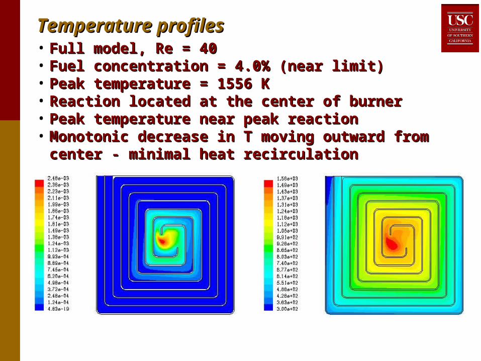
Temperature profilesTemperature profiles• Full model, Re = 40Full model, Re = 40• Fuel concentration = 4.0% (near limit)Fuel concentration = 4.0% (near limit)• Peak temperature = 1556 KPeak temperature = 1556 K• Reaction located at the center of burnerReaction located at the center of burner• Peak temperature near peak reactionPeak temperature near peak reaction• Monotonic decrease in T moving outward from center - Monotonic decrease in T moving outward from center -
minimal heat recirculationminimal heat recirculation

Reaction rate Temperature
Full model, higher ReFull model, higher Re• Full model, Re = 100Full model, Re = 100• Fuel concentration = 1.1% (near limit)Fuel concentration = 1.1% (near limit)• Peak temperature = 1418 KPeak temperature = 1418 K• Reaction zone more spread out - higher u, shorter Reaction zone more spread out - higher u, shorter
residence timeresidence time• More T contrast between inlet & outlet turns - less effect of More T contrast between inlet & outlet turns - less effect of
wall heat conduction, but still nearly monotonic decrease wall heat conduction, but still nearly monotonic decrease in T moving from center outwardin T moving from center outward

Reaction rate Temperature
Full model, “very” high ReFull model, “very” high Re• Full model, Re = 1000Full model, Re = 1000• Fuel concentration = 1.3% (near limit)Fuel concentration = 1.3% (near limit)• Peak temperature = 1862 KPeak temperature = 1862 K• Reaction zone still more spread out Reaction zone still more spread out • Still more T contrast between inlet & outlet turns - finally Still more T contrast between inlet & outlet turns - finally
getting alternating low T / high T in inlet / outlet turns getting alternating low T / high T in inlet / outlet turns
Reaction rate Temperature
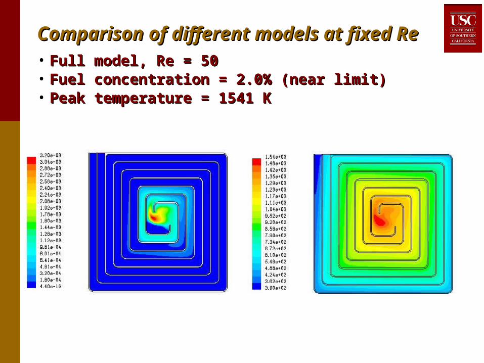
Comparison of different models at fixed ReComparison of different models at fixed Re• Full model, Re = 50Full model, Re = 50• Fuel concentration = 2.0% (near limit)Fuel concentration = 2.0% (near limit)• Peak temperature = 1541 KPeak temperature = 1541 K

Reaction rate Temperature
Full model without radiationFull model without radiation• Full model without radiation, Re = 50Full model without radiation, Re = 50• Fuel concentration = 0.8% (near limit)Fuel concentration = 0.8% (near limit)• Peak temperature = 1388 KPeak temperature = 1388 K• Not significantly different structure, but central core is Not significantly different structure, but central core is
less isothermal due to absence of radiationless isothermal due to absence of radiation• Limit fuel concentration is WAY different!Limit fuel concentration is WAY different!

Full model without heat lossFull model without heat loss• Full model without heat loss, Re = 50Full model without heat loss, Re = 50• Fuel concentration = 0.7% (near limit)Fuel concentration = 0.7% (near limit)• Peak temperature = 1104 KPeak temperature = 1104 K• Central region nearly isothermal (no 3D loss)Central region nearly isothermal (no 3D loss)• As expected, low limit fuel concentrationAs expected, low limit fuel concentration
Reaction rate Temperature

Catalytic combustion modelingCatalytic combustion modeling• Collaborator: Kaoru Maruta (Tohoku Univ., Sendai, Japan)Collaborator: Kaoru Maruta (Tohoku Univ., Sendai, Japan)• Detailed catalytic combustion model (Deutschmann Detailed catalytic combustion model (Deutschmann et alet al.) .)
integrated into FLUENT integrated into FLUENT • ModelModel
• Cylindrical tube reactor, 1 mm dia. x 10 mm length, no wall Cylindrical tube reactor, 1 mm dia. x 10 mm length, no wall thermal conductionthermal conduction
• Platinum catalyst, CHPlatinum catalyst, CH44-air and CH-air and CH44-O-O22-N-N22 mixtures mixtures• Heat loss to ambientHeat loss to ambient
Wall boundary condition H = 0, 5 or10 W/m2˚C
1 mmnon-catalytic wall
9 mmcatalytic wall
Fuel/airinlet
1 mmdiameter
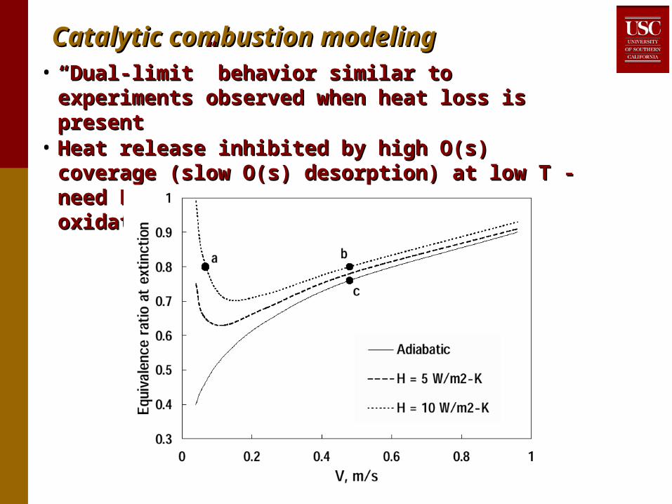
Catalytic combustion modelingCatalytic combustion modeling• ““Dual-limit” behavior similar to experiments observed Dual-limit” behavior similar to experiments observed
when heat loss is presentwhen heat loss is present• Heat release inhibited by high O(s) coverage (slow Heat release inhibited by high O(s) coverage (slow
O(s) desorption) at low T - need Pt(s) sites for fuel O(s) desorption) at low T - need Pt(s) sites for fuel adsorption / oxidationadsorption / oxidation

Catalytic combustion modelingCatalytic combustion modeling
• Computations with fuel:OComputations with fuel:O22 fixed, N fixed, N22 (not air) dilution (not air) dilution• Minimum fuel concentration & T needed to sustain Minimum fuel concentration & T needed to sustain
combustion much lower for even slightly rich mixtures!combustion much lower for even slightly rich mixtures!• Behavior due to transition from O(s) coverage for lean Behavior due to transition from O(s) coverage for lean
mixtures (excess Omixtures (excess O22) to CO(s) coverage for rich mixtures ) to CO(s) coverage for rich mixtures
(excess fuel)(excess fuel)
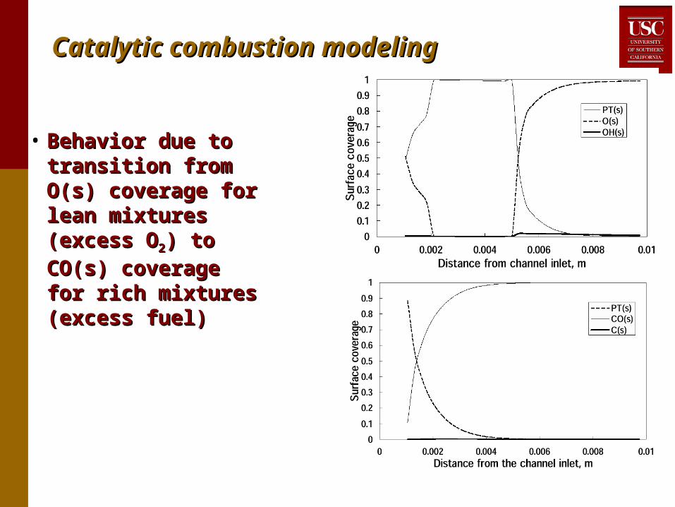
Catalytic combustion modelingCatalytic combustion modeling
• Behavior due to Behavior due to transition from O(s) transition from O(s) coverage for lean coverage for lean mixtures (excess Omixtures (excess O22) )
to CO(s) coverage for to CO(s) coverage for rich mixtures (excess rich mixtures (excess fuel)fuel)
Lean
Rich

Modeling - comparison with experimentsModeling - comparison with experiments• Predictions Predictions qualitativelyqualitatively consistent with experiments (propane- consistent with experiments (propane-
OO22-N-N22) in Swiss roll (not straight tube) at low Re) in Swiss roll (not straight tube) at low Re• No analogous behavior without catalyst No analogous behavior without catalyst • Comment: typical strategy to reduce flame temperature: dilute Comment: typical strategy to reduce flame temperature: dilute
with excess air, but with catalytic combustion: better strategy is with excess air, but with catalytic combustion: better strategy is to dilute with material containing no Oto dilute with material containing no O22, i.e. slightly rich mixtures , i.e. slightly rich mixtures with with exhaust gas dilutionexhaust gas dilution
1
1.5
2
2.5
3
3.5
500
600
700
800
900
0.4 0.6 0.8 1 1.2 1.4
% Fuel (non-Cat.)% Fuel (Cat.)
Tmax
(non-Cat.)
Tmax
(Cat.)
Equivalence Ratio
Re = 100C
3H
8-O
2-N
2 mixtures

• Same principal as thermocouple, material Same principal as thermocouple, material optimized for power generationoptimized for power generation
• Imbed in wall between hot (outgoing product) Imbed in wall between hot (outgoing product) and cold (incoming reactant) streamsand cold (incoming reactant) streams
• US Patent No. US Patent No. 6,613,972 (9/2/2003)
Power generation - thermoelectricsPower generation - thermoelectrics
Hot side
Cold side
Load
Overall configuration - Wall itself is electrical Overall configuration - Wall itself is electrical conductorconductor
Typical thermoelectric Typical thermoelectric configuration - alternating configuration - alternating
n- and p-type elementsn- and p-type elements
Products
Reactants
Combustionvolume
1600 1200 400 300 K500
1400 600 5007001600
Thermoelectric elements

• Widely used in deep space missions, some commercial applications Widely used in deep space missions, some commercial applications (mostly used in reverse for cooling, not power generation)(mostly used in reverse for cooling, not power generation)
• TE efficiency typically 15% of Carnot with same TE efficiency typically 15% of Carnot with same TT• Recent development: “quantum well” thermoelectrics, many bold Recent development: “quantum well” thermoelectrics, many bold
claimsclaims
ThermoelectricsThermoelectrics
0
0.05
0.1
0.15
0.2
200 300 400 500 600 700 800
p-type PbTen-type PbTep-type Bi
2Te
3
n-type Bi2Te
3
Temperature (K)

Thermoelectric microgenerator problemThermoelectric microgenerator problem• TE wall material: thermal TE wall material: thermal
conductivity k ≈ 1 W/m˚Cconductivity k ≈ 1 W/m˚C• Gas: k ≈ 0.025 - 0.1 Gas: k ≈ 0.025 - 0.1
W/m˚CW/m˚C Thermal resistance Thermal resistance
between gas & TE wall between gas & TE wall >> resistance across TE>> resistance across TE
Most Most T between gas & T between gas & TE wall, not across TETE wall, not across TE
No power generation!No power generation!• Need “dirty tricks” for Need “dirty tricks” for
microscale devices!microscale devices!• Macroscale devices - Macroscale devices -
strong turbulence, strong turbulence, convective heat transfer, convective heat transfer, low thermal resistance, low thermal resistance, but microscale Reynolds but microscale Reynolds # too low!# too low!
TEelement
(k = 1 W/m˚C)
Hot gas(k = 0.1 W/m˚C)
Desired Tprofile
Actual Tprofile
Cold gas(k = 0.025 W/m˚C)
Xd d

““Dirty tricks…”Dirty tricks…”
• Integrated TE wall & T-fin design greatly reduces RIntegrated TE wall & T-fin design greatly reduces Rgsgs/R/RTETE
- - without massive pressure drops due to aggressive fins without massive pressure drops due to aggressive fins in flow channelin flow channel• Metal fins (blue) have high thermal conductivity - act as Metal fins (blue) have high thermal conductivity - act as
thermal short-circuitthermal short-circuit• Air acts as thermal open-circuitAir acts as thermal open-circuit• Elongating base of T-fin and TE walls reduces RElongating base of T-fin and TE walls reduces Rgsgs/R/RTETE • US Patent No. US Patent No. 6,613,972 (9/2/2003)
n-typesemiconductor
p-typesemiconductor
structuralmetal
HOTGAS
COLDGAS
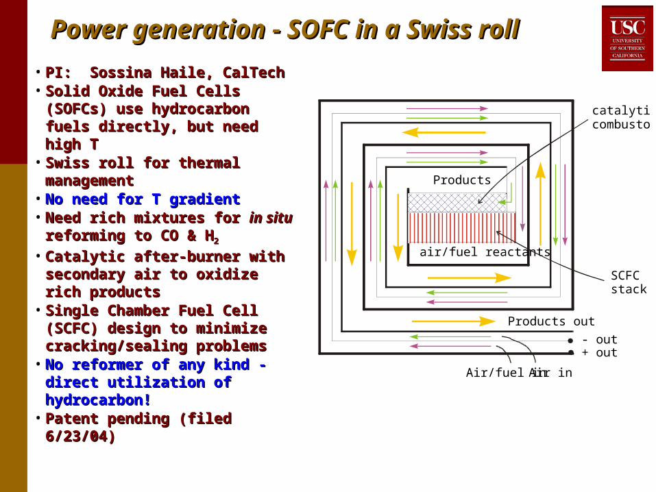
Power generation - SOFC in a Swiss rollPower generation - SOFC in a Swiss roll
• PI: Sossina Haile, CalTechPI: Sossina Haile, CalTech• Solid Oxide Fuel Cells (SOFCs) Solid Oxide Fuel Cells (SOFCs)
use hydrocarbon fuels directly, use hydrocarbon fuels directly, but need high Tbut need high T
• Swiss roll for thermal Swiss roll for thermal management management
• No need for T gradientNo need for T gradient• Need rich mixtures for Need rich mixtures for in situin situ
reforming to CO & Hreforming to CO & H22
• Catalytic after-burner with Catalytic after-burner with secondary air to oxidize rich secondary air to oxidize rich products products
• Single Chamber Fuel Cell Single Chamber Fuel Cell (SCFC) design to minimize (SCFC) design to minimize cracking/sealing problemscracking/sealing problems
• No reformer of any kind - direct No reformer of any kind - direct utilization of hydrocarbon!utilization of hydrocarbon!
• Patent pending (filed 6/23/04)Patent pending (filed 6/23/04)
Products out
Air inAir/fuel in
- out+ out
Products
air/fuel reactants
catalyticcombustor
SCFCstack

Single Chamber Solid Oxide Fuel CellsSingle Chamber Solid Oxide Fuel Cells
CHCH44 + 1/2 O + 1/2 O22 CO + 2H CO + 2H22
HH22 + O + O== H H22O + 2eO + 2e--
CO + OCO + O== CO CO22 + 2e + 2e--
CnH2n+2 O2O2
O=
C
C
O
O
+
+
CO2 + H2
H2
O
cathodeanode
e-e-
1/2 O2 + 2e- O=
fuel + oxidant by-products
• Introduced by Hibino Introduced by Hibino et al.et al. Science (2000) Science (2000)• Fuel & oxidant mixed - no sealing issues, no coking problemsFuel & oxidant mixed - no sealing issues, no coking problems• Highly selective anode & cathode catalysts essential since fuel Highly selective anode & cathode catalysts essential since fuel
& oxidant exposed to both anode & cathode& oxidant exposed to both anode & cathode
conventional SOFC
fuel oxidant
CH4 + 4O=
CO2 + 2H2O +8e-1/2 O2 + 2e- O=
seals
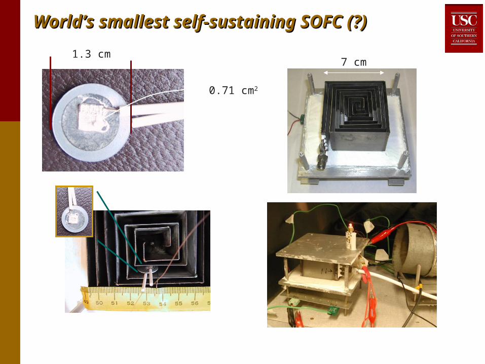
World’s smallest self-sustaining SOFC (?)World’s smallest self-sustaining SOFC (?)
7 cm1.3 cm
0.71 cm2

Single Chamber Fuel Cell in Swiss rollSingle Chamber Fuel Cell in Swiss roll• Maximum power density ≈ 375 mW/cmMaximum power density ≈ 375 mW/cm22 at T ≈ 540˚C at T ≈ 540˚C
demonstrated demonstrated with direct utilization of hydrocarbon fuelwith direct utilization of hydrocarbon fuel
0
0.1
0.2
0.3
0.4
0.5
0.6
0.7
0.8
0
50
100
150
200
250
300
350
400
0 200 400 600 800 1000 1200 1400
Current density (mA/cm2)
T = 540˚CO
2:C
3H
8 = 2.07:1

150
200
250
300
350
400
450
460 480 500 520 540 560 580 600 620
2 2.1 2.2 2.3 2.4 2.5
Temperature effect (O2:fuel = 2.07)
O2:fuel effect (T = 550˚C)
Cell temperature (˚C)
Fuel to O2 mole ratio
Effect of cell temperature and OEffect of cell temperature and O22:fuel ratio:fuel ratio• Much lower T than conventional SOFC; significant power Much lower T than conventional SOFC; significant power
production even at 400˚Cproduction even at 400˚C• Performance not to sensitive to temperature - range of T within Performance not to sensitive to temperature - range of T within
20% of max. power ≈ ±50˚C20% of max. power ≈ ±50˚C• Performance sensitive to OPerformance sensitive to O22:fuel ratio - best results at lower :fuel ratio - best results at lower
OO22:fuel ratio (closer to stoichiometric but still fuel-rich):fuel ratio (closer to stoichiometric but still fuel-rich)

SummarySummary
• Microscale power and propulsion devices may requireMicroscale power and propulsion devices may require• Heat recirculation (e.g. Swiss roll)Heat recirculation (e.g. Swiss roll)• Catalytic combustion, slightly rich mixturesCatalytic combustion, slightly rich mixtures• Thin walls made of low conductivity materialsThin walls made of low conductivity materials• Non-conventional power generation & pumping concepts - Non-conventional power generation & pumping concepts -
no moving partsno moving parts• Combustion behavior different from “conventional” Combustion behavior different from “conventional”
macroscale systemsmacroscale systems• Air (or aerogels) are good insulators - ceramics are not, Air (or aerogels) are good insulators - ceramics are not,
even plastics are marginaleven plastics are marginal• Polymer meso- or micro-combustors appear feasible and Polymer meso- or micro-combustors appear feasible and
may be advantageousmay be advantageous• 72˚C - 400˚C sustained operation demonstrated72˚C - 400˚C sustained operation demonstrated• Good low-Re performance (low k)Good low-Re performance (low k)• Inexpensive, durable, many fabrication optionsInexpensive, durable, many fabrication options

Summary - generalSummary - general
• Study and applications of microscale Study and applications of microscale thermal/chemical systems is a promising new thermal/chemical systems is a promising new technology in its infancytechnology in its infancy
• Many potential applicationsMany potential applications• Power generationPower generation• PropulsionPropulsion• Chemical or biological sensorsChemical or biological sensors• ……
• Not as crowded as “traditional” MEMSNot as crowded as “traditional” MEMS

Blue-sky pipe dream complete systemBlue-sky pipe dream complete system• Polymer 3D Swiss rollPolymer 3D Swiss roll• Hydrocarbon fuel, self-starting at room temperatureHydrocarbon fuel, self-starting at room temperature• Single-chamber solid oxide fuel cell or quantum well Single-chamber solid oxide fuel cell or quantum well
thermoelectrics for power generation - thermoelectrics for power generation - direct utilization of direct utilization of hydrocarbonshydrocarbons
• Thermal transpiration pumping of fuel/air mixture - no moving Thermal transpiration pumping of fuel/air mixture - no moving parts, uses thermal energy, not electrical energyparts, uses thermal energy, not electrical energy

USC contributions to microthermochemical USC contributions to microthermochemical systemssystems
• DesignsDesigns• Thermoelectric Swiss roll generatorThermoelectric Swiss roll generator• Fin design for thermoelectric power generationFin design for thermoelectric power generation• Use of SOFC in a Swiss rollUse of SOFC in a Swiss roll• Catalytic combustion based thermal transpiration propulsionCatalytic combustion based thermal transpiration propulsion• Multi-stage thermal transpiration pumping using Swiss rollMulti-stage thermal transpiration pumping using Swiss roll
• FundamentalsFundamentals• Identified flameless combustion in broad reaction zones in heat-Identified flameless combustion in broad reaction zones in heat-
recirculating burnersrecirculating burners• Stability of gas-phase & catalytic modesStability of gas-phase & catalytic modes• Tradeoffs between gas-phase & catalytic combustionTradeoffs between gas-phase & catalytic combustion• Effect of equivalence ratio (independent of flame temperature) on Effect of equivalence ratio (independent of flame temperature) on
catalytic combustioncatalytic combustion• Effect of wall thermal conductivityEffect of wall thermal conductivity• Effect of heat losses in 3rd dimensionEffect of heat losses in 3rd dimension• Importance of radiation in scale-downImportance of radiation in scale-down