Embed Size (px)
Citation preview
8/13/2019 Microprocessors and Timers
http://slidepdf.com/reader/full/microprocessors-and-timers 1/3
MSc. Ivan A. EscobarMicroprocessors 1 1
Microprocessors 1
Timers/Counters
MSc. Ivan A. EscobarMicroprocessors 1 2
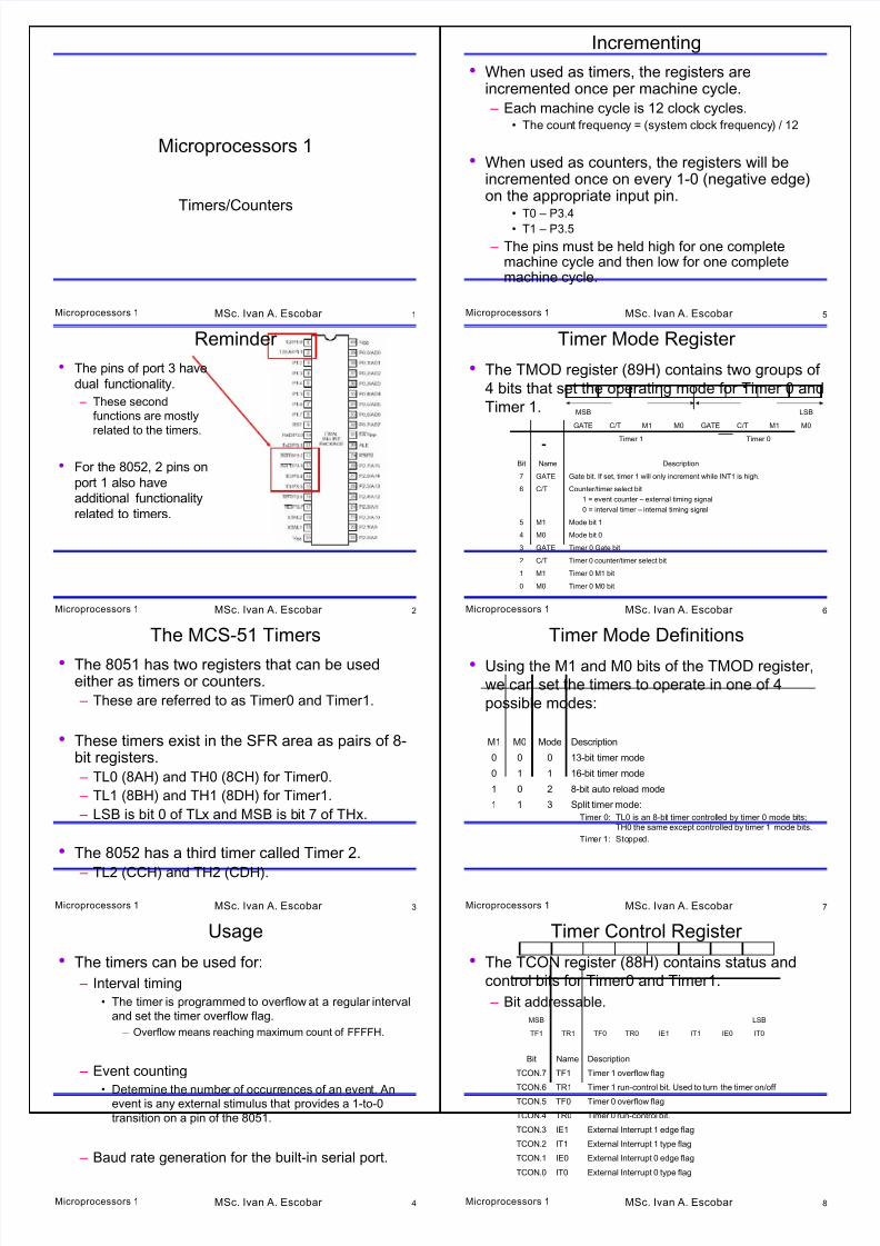
Reminder
• The pins of port 3 have
dual functionality.
– These second
functions are mostly
related to the timers.
• For the 8052, 2 pins on
port 1 also have
additional functionality
related to timers.
MSc. Ivan A. EscobarMicroprocessors 1 3
The MCS-51 Timers
• The 8051 has two registers that can be usedeither as timers or counters.
– These are referred to as Timer0 and Timer1.
• These timers exist in the SFR area as pairs of 8-bit registers.
– TL0 (8AH) and TH0 (8CH) for Timer0.
– TL1 (8BH) and TH1 (8DH) for Timer1.
– LSB is bit 0 of TLx and MSB is bit 7 of THx.
• The 8052 has a third timer called Timer 2.
– TL2 (CCH) and TH2 (CDH).
MSc. Ivan A. EscobarMicroprocessors 1 4
Usage
• The timers can be used for:
– Interval timing
• The timer is programmed to overflow at a regular interval
and set the timer overflow flag.
– Overflow means reaching maximum count of FFFFH.
– Event counting
• Determine the number of occurrences of an event. Anevent is any external stimulus that provides a 1-to-0
transition on a pin of the 8051.
– Baud rate generation for the built-in serial port.
MSc. Ivan A. Escobar Microprocessors 1 5
Incrementing
• When used as timers, the registers areincremented once per machine cycle.
– Each machine cycle is 12 clock cycles.• The count frequency = (system clock frequency) / 12
• When used as counters, the registers will beincremented once on every 1-0 (negative edge)on the appropriate input pin.
• T0 – P3.4• T1 – P3.5
– The pins must be held high for one completemachine cycle and then low for one completemachine cycle.
MSc. Ivan A. Escobar Microprocessors 1 6
Timer Mode Register
• The TMOD register (89H) contains two groups of
4 bits that set the operating mode for Timer 0 and
Timer 1.
Timer 0Timer 1
M0M1C/TGATEM0M1C/TGATE
LSBMSB
Timer 0 M0 bitM00
Timer 0 M1 bitM11
Timer 0 counter/timer select bitC/T2
Timer 0 Gate bitGATE3
Mode bit 0M04
Mode bit 1M15
Counter/timer select bit
1 = event counter – external timing signal
0 = interval timer – internal timing signal
C/T6
Gate bit. If set, timer 1 will only increment while INT1 is high.GATE7
DescriptionNameBit
MSc. Ivan A. Escobar Microprocessors 1 7
Timer Mode Definitions
• Using the M1 and M0 bits of the TMOD register,
we can set the timers to operate in one of 4
possible modes:
Split timer mode:
Timer 0: TL0 is an 8-bit timer controlled by timer 0 mode bits;TH0 the same except controlled by timer 1 mode bits.
Timer 1: Stopped.
311
8-bit auto reload mode201
16-bit timer mode110
13-bit timer mode000
DescriptionModeM0M1
MSc. Ivan A. Escobar Microprocessors 1 8
Timer Control Register
• The TCON register (88H) contains status and
control bits for Timer0 and Timer1.
– Bit addressable.
IT0IE0IT1IE1TR0TF0TR1TF1
LSBMSB
External Interrupt 0 type flagIT0TCON.0
External Interrupt 0 edge flagIE0TCON.1
External Interrupt 1 type flagIT1TCON.2
External Interrupt 1 edge flagIE1TCON.3
Timer 0 run-control bit.TR0TCON.4
Timer 0 overflow flagTF0TCON.5
Timer 1 run-control bit. Used to turn the timer on/off TR1TCON.6
Timer 1 overflow flagTF1TCON.7
DescriptionNameBit

8/13/2019 Microprocessors and Timers
http://slidepdf.com/reader/full/microprocessors-and-timers 2/3
MSc. Ivan A. EscobarMicroprocessors 1 9
Mode 0/1
• In mode 1, the timer/counter is configured as a 16-bittimer/counter.
– The upper 8 bits of the count are in TH
– The lower 8 bits are in TL.
• In mode 0, the timer/counter is configured as a 13-bittimer/counter.
• Used for backward compatibility with the 8048.
– The upper 8 bits of the count are in TH
– The lower 5 bits are in the lower 5 bits of TL.
– The upper 3 bits of TL are not used
• The TFx flag will be set when the counter switches from all1’s to all 0’s.
– The timer continues to count.
MSc. Ivan A. EscobarMicroprocessors 1 10
Mode 2
• 8-bit Auto-Reload Mode
– TL operates as an 8-bit counter.
– TH holds a reload value.• When TL overflows (reached FFH), the TFx flag is set,
TL is reloaded from the value in TH and countingcontinues.
– To make counter 0 count 40H times:• Set TH0 to BFH
• Set the counter to mode 2.
• Run the counter.
• Once it reached FFH, it will reload with BFH and repeat.
MSc. Ivan A. EscobarMicroprocessors 1 11
Mode 3
• Split timer mode.
• Timer 0 is split into two independent 8-bit timers.
– When TL0 overflows, it sets the TF0 flag.
– When TH0 overflows, it sets the TF1 flag.
• Timer 1 is stopped in mode 3.
– It can be switched independently to a different
mode.
• However, when it overflows it will NOT set the TF1 flag.
MSc. Ivan A. EscobarMicroprocessors 1 12
Clocking Sources
• There are two possible clock sources for the timerscontrolled by the C/T bit of each timer in the TMODregister.
• If C/T = 0, continuous timer operation is selected and thetimer is clocked from by the system clock divided by 12.
– The timer is being used for interval timing.
– Timer overflow occurs after a certain number of cyclesdepending on the initial value stored in TLx/THx.
• If C/T = 1, the timer is clocked from an external source(pin T0 or T1 on port 3).
– The timer is being used for event counting.
– The number of events is stored as a 16-bit hexadecimalvalue in TLx/THx.
MSc. Ivan A. Escobar Microprocessors 1 13
Starting, Stopping and Controlling the Timers
• The simplest method for starting and stopping
the timers is by setting/clearing the TRx bit in
TCON.
– TRx is cleared after a reset.
• It has to be set by software to start the timer.
– TCON is bit addressable.
• SETB TR0
• CLR TR0
MSc. Ivan A. Escobar Microprocessors 1 14
Starting, Stopping and Controlling the Timers
• The other possibility is by using the GATE bit of
TMOD and the external input INTx.
– Setting GATE = 1 allows the timer to be controlled
by INTx.
• When INTx goes high, the counter is enabled and counts
at a rate of system clock/12.
• When INTx goes low, the counter is disabled.
MSc. Ivan A. Escobar Microprocessors 1 15
Initializing the Timer Registers
• TMOD is the first register initialized since it sets the mode
of operation.
MOV TMOD, #00010000B
– This sets Timer 1 into mode 1 clocked from the on-chip
oscillator.
• An initial value is stored in THx/TLx if necessary.
MOV TL1, #9CH
MOV TH1, #0FFH
– This will set the starting value of Timer1 to FF9CH.
• Timer1 will count 100 cycles before overflowing.
• To start the timer, we need to set the right TRx bit.
SETB TR1
MSc. Ivan A. Escobar Microprocessors 1 16
Monitoring the Timer
• It is possible to write an ISR that responds when
the timer overflows. Then we can enable the
appropriate interrupt bit in the IE register and let
the microcontroller respond automatically.
• Or, we can write a wait loop and monitor the
timer flag TFx.WAIT: JNB TF1, WAIT
– When the counter reaches FFFFH and turns to
0000H, the TF1 bit will be set and the program will
break out of the loop.
8/13/2019 Microprocessors and Timers
http://slidepdf.com/reader/full/microprocessors-and-timers 3/3
MSc. Ivan A. EscobarMicroprocessors 1 17
Responding to a Timer Overflow
• When the timer overflows, we need to stop it and
then reset the TFx bit so that we don’t generate
false overflows.CLR TR1
CLR TF1