Embed Size (px)
Citation preview
Microprocessor
Lecture (2)
1

• Introduction to instruction set architecture, microarchitecture and system architecture
• Microcomputer architecture and Basic Blocks of a Microcomputer
• Introduction to microprocessor
• Simplified Explanation of Control Unit design
• Program Execution by Conventional Microprocessors
• Pipeline
• Branch Prediction Feature
• Scalar and Superscalar Microprocessors
• Microprocessor architectures RISC vs. CISC
• Microprocessor Data Types
• Evolution of the microprocessor
Outline
2
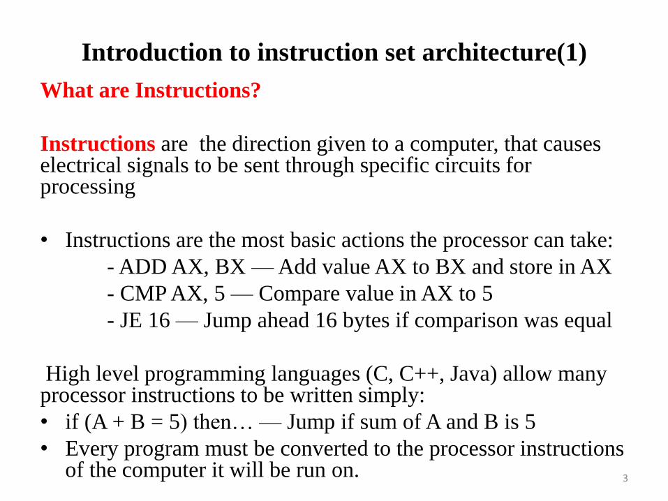
Introduction to instruction set architecture(1)
What are Instructions?
Instructions are the direction given to a computer, that causes electrical signals to be sent through specific circuits for processing
• Instructions are the most basic actions the processor can take:
- ADD AX, BX — Add value AX to BX and store in AX
- CMP AX, 5 — Compare value in AX to 5
- JE 16 — Jump ahead 16 bytes if comparison was equal
High level programming languages (C, C++, Java) allow many processor instructions to be written simply:
• if (A + B = 5) then… — Jump if sum of A and B is 5
• Every program must be converted to the processor instructions of the computer it will be run on.
3

Introduction to instruction set architecture (2)
• Instruction set
– Design defines functions performed by the processor
– Differentiates computer architecture by the
• Number of instructions
• Complexity of operations performed by individual instructions
• Data types supported
• Format (layout, fixed vs. variable length)
• Use of registers
• Addressing (size, modes)
4
Introduction to instruction set architecture (ISA) (3)
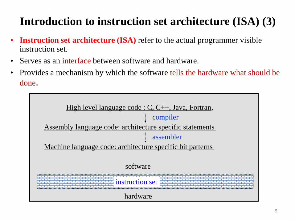
• Instruction set architecture (ISA) refer to the actual programmer visible instruction set.
• Serves as an interface between software and hardware.
• Provides a mechanism by which the software tells the hardware what should be
done.
instruction set
High level language code : C, C++, Java, Fortran,
hardware
Assembly language code: architecture specific statements
Machine language code: architecture specific bit patterns
software
compiler
assembler
5

Introduction to instruction set architecture (4)
• Instruction set design issues include:
– Where are operands stored?
• registers, memory, stack, accumulator
– How many explicit operands are there?
• 0, 1, 2, or 3
– How is the operand location specified?
• register, immediate, indirect, . . .
– What type & size of operands are supported?
• byte, int, float, double, string, vector. . .
– What operations are supported?
• add, sub, mul, move, compare . . .
6
Microarchitecture and system architecture (1)
What is Computer Architecture?
• The science and art of designing, selecting, and interconnecting hardware components and designing the hardware/software interface to create a computing system that meets functional, performance, energy consumption, cost, and other specific goals.
• “The term architecture is used to describe the attributes of a system as seen by the programmer, i.e., the conceptual structure and functional behavior as distinct from the organization of the dataflow and controls, the logic design, and the physical implementation.” Gene Amdahl, IBM Journal of R&D, April 1964
7
8
Microarchitecture and system architecture (2)
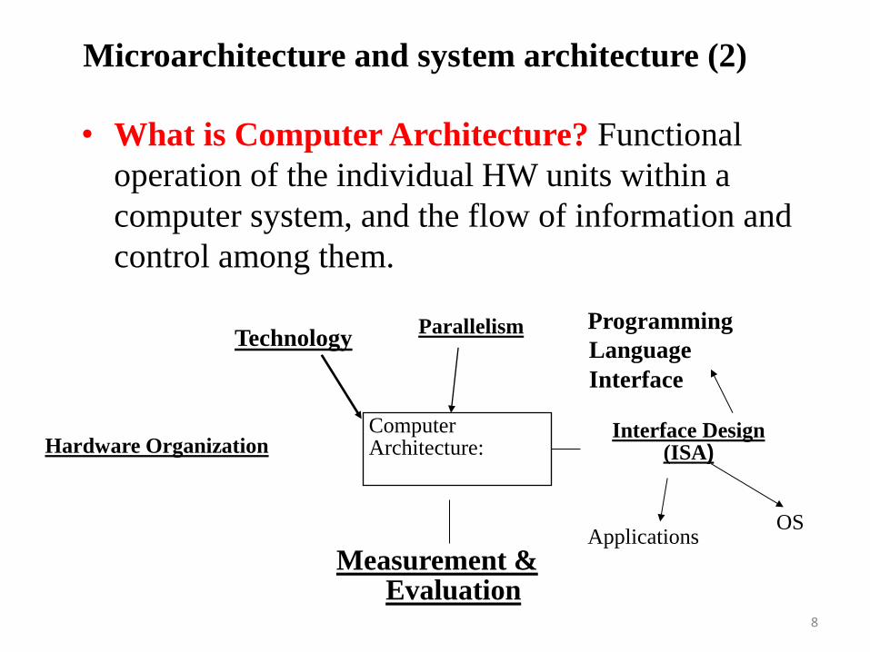
• What is Computer Architecture? Functional
operation of the individual HW units within a
computer system, and the flow of information and
control among them.
Technology
Programming
Language
Interface
Interface Design (ISA)
Measurement & Evaluation
Parallelism
Computer Architecture:
Applications OS
Hardware Organization

Microarchitecture and system architecture (3)
• The task the computer designer faces is a complex one:
Determine what attributes are important for a new
computer,
• Then design a computer to maximize :
- performance and
- Energy efficiency,
while staying within : cost, power, and availability constraints.
• This task has many aspects, including instruction set design,
functional organization, logic design, and implementation.
• Architecture is concerned with internal structures of each, interconnections
( speed and width) , and relative speeds of components
• Want maximum execution speed Balance is often critical issue.
9
Microarchitecture and system architecture (4)
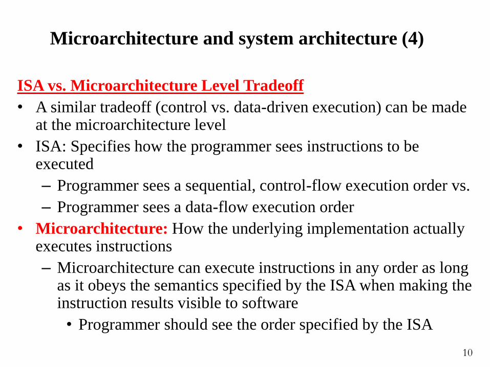
ISA vs. Microarchitecture Level Tradeoff
• A similar tradeoff (control vs. data-driven execution) can be made at the microarchitecture level
• ISA: Specifies how the programmer sees instructions to be executed
– Programmer sees a sequential, control-flow execution order vs.
– Programmer sees a data-flow execution order
• Microarchitecture: How the underlying implementation actually executes instructions
– Microarchitecture can execute instructions in any order as long as it obeys the semantics specified by the ISA when making the instruction results visible to software
• Programmer should see the order specified by the ISA
10
Microarchitecture and system architecture (5)
• Microarchitecture is the steps a processor takes to execute a particular set of instructions.
• Processors of the same architecture have the same instructions but may carry them out in different ways.
• Microarchitecture Features:
–Cache memory
–Pipelining
–Out-of-Order Execution
–Superscalar Issue
11
Microcomputer architecture and Basic Blocks of a Microcomputer
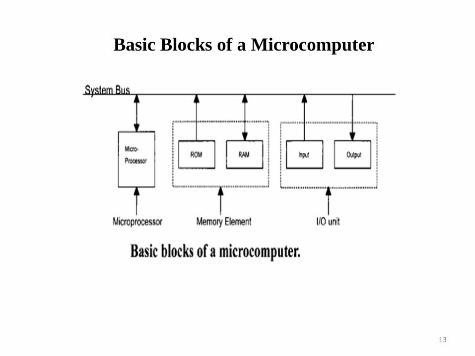
Basic Blocks of a Microcomputer
A microcomputer has three basic blocks: a central processing unit (CPU), a memory unit,
and an input/output (I/O) unit.
The CPU(microprocessor) executes all the instructions and performs arithmetic and logic operations on data.
A memory unit stores both data and instructions. The memory section typically
contains ROM and RAM chips.
A system bus (comprised of several wires) connects these blocks.
12
Basic Blocks of a Microcomputer
13
• In a single-chip microcomputer, these three
elements are on one chip, whereas
• in a single-chip microprocessor, separate chips
are required for memory and I/O.
Microcomputer architecture and Basic Blocks of a Microcomputer
14
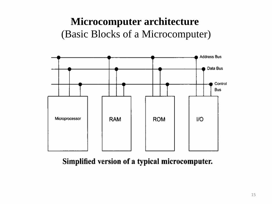
Microcomputer architecture
(Basic Blocks of a Microcomputer)
15

Introduction to Microprocessor MPU
• Microprocessor MPU is fabricate a CPU on a
single chip
• Along with the microprocessor chip, appropriate
memory and I/O chips can be used to design a
microcomputer (with CPU being a microprocessor)
• Microcontrollers include a microcomputer,
timers, and A/D (analog-to- digital) and D/A
(digital to analog) converters, all on a single chip.
16
Introduction to Microprocessor MPU
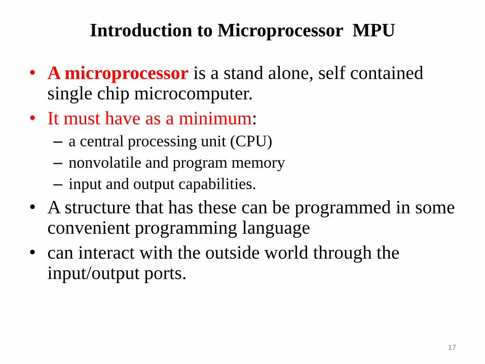
• A microprocessor is a stand alone, self contained single chip microcomputer.
• It must have as a minimum:
– a central processing unit (CPU)
– nonvolatile and program memory
– input and output capabilities.
• A structure that has these can be programmed in some convenient programming language
• can interact with the outside world through the input/output ports.
17

Introduction to the microprocessor
• Other important requirements: • must be relatively simple
• reasonably small
• necessarily limited in most of its features – memory,
processing power and speed, addressing range and, of
course in number of I/O devices it can interact with.
• The designer must have access to all features of the
microprocessor – bus, memory, registers, all I/O ports,
• In short, Microprocessors are components with
flexible features that the engineer can configure and
program to perform task or a series of tasks.
18
Arithmetic
Logic
Unit
Register
Arrays
Control Unit
GP-
CPU CLK Reg
MPU
CPU
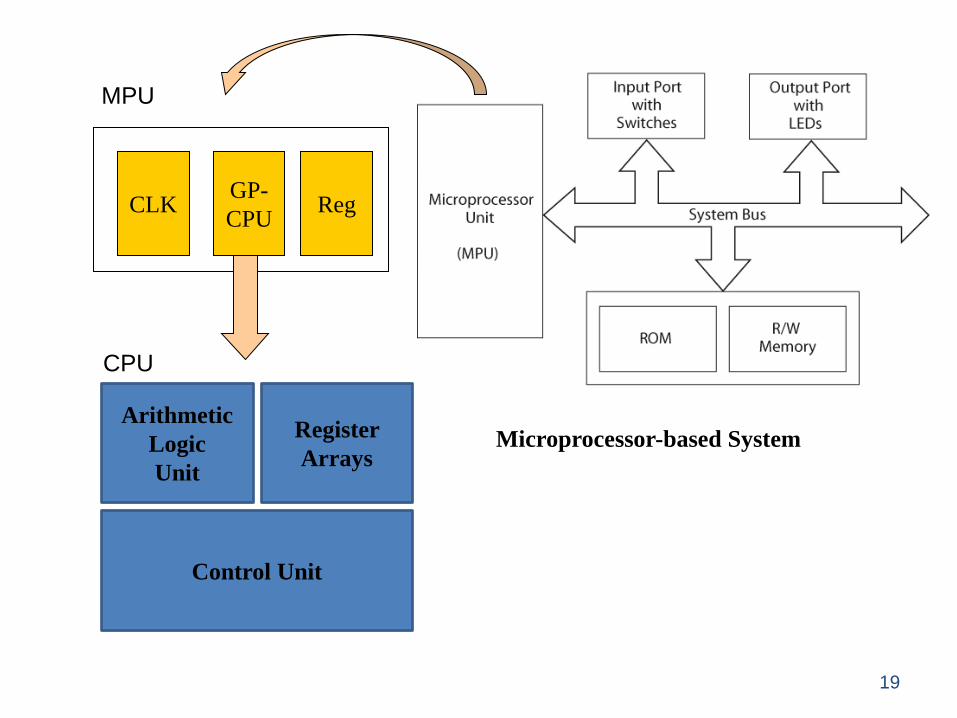
Microprocessor-based System
19
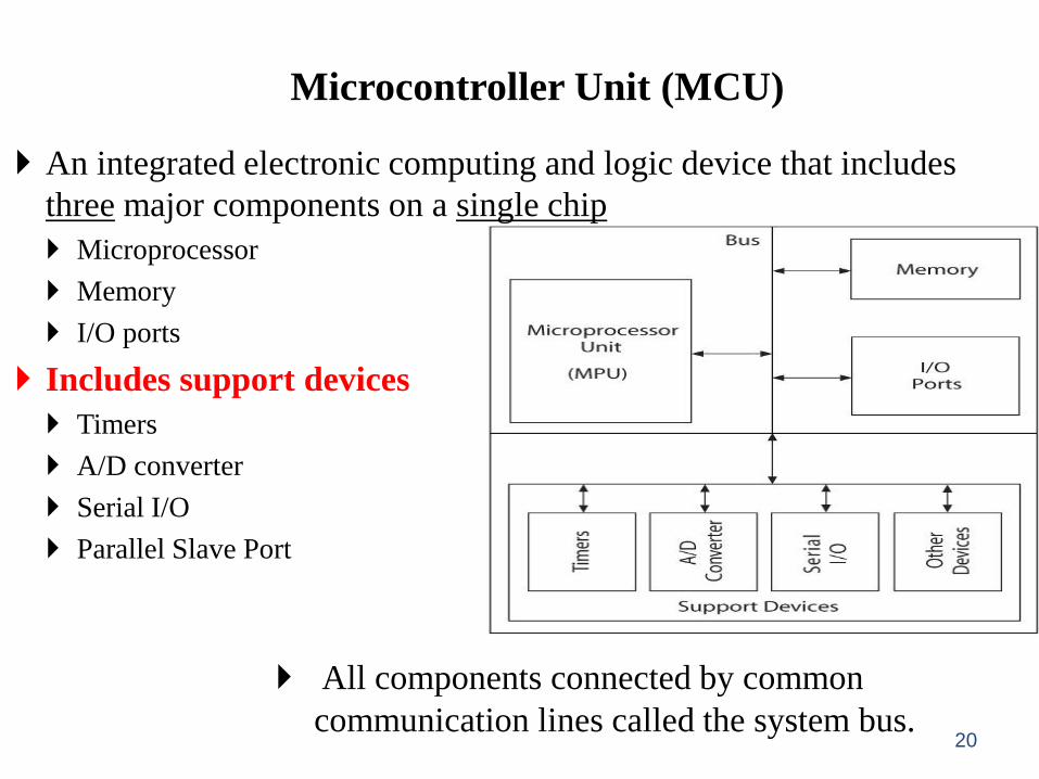
Microcontroller Unit (MCU)
An integrated electronic computing and logic device that includes
three major components on a single chip
Microprocessor
Memory
I/O ports
Includes support devices
Timers
A/D converter
Serial I/O
Parallel Slave Port
All components connected by common
communication lines called the system bus. 20
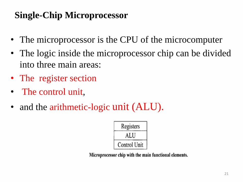
• The microprocessor is the CPU of the microcomputer
• The logic inside the microprocessor chip can be divided
into three main areas:
• The register section
• The control unit,
• and the arithmetic-logic unit (ALU).
Single-Chip Microprocessor
21
• Register is a Small, permanent storage locations within the CPU used for a particular purpose
• Manipulated directly by the Control Unit
• Wired for specific function
• Size in bits or bytes (not MB like memory)
• Can hold data, an address or an instruction
• The number, size, and types of registers vary from one microprocessor to another.
Basic Microprocessor Registers
There are four basic microprocessor registers: instruction register, program counter, memory address register, and accumulator.
Register Section
22
Instruction register (IR) :
• The instruction register stores instructions.
• The word size of the microprocessor determines the
size of the instruction register. For example, a 32-bit
microprocessor has a 32-bit instruction register.
Register Section
23
Program Counter (PC):
• The program counter contains the address of the
instruction or operation code (op-code).
• The program counter normally contains the address
of the next instruction to be executed.
• The size of the program counter is determined by the
size of the address bus.
Register Section
24

How Program Counter is Work ?
1. Upon activating the microprocessor’s RESET input, the address
of the first instruction to be executed is loaded into the program
counter.
2. To execute an instruction, the microprocessor typically places the
contents of the program counter on the address bus and reads
(“fetches”) the contents of this address(i.e., instruction) from
memory
3. The program counter contents are incremented automatically by
the microprocessor’s internal logic. Microprocessor executes a
program sequentially, unless the program contains an instruction
such as a JUMP instruction, which changes the sequence.
Register Section
25
Memory Address Register (MAR).
The memory address register contains the address of
data.
The microprocessor uses the address, which is stored in
the memory address register, as a direct pointer to
memory. The contents of the address is the actual data
that is being transferred.
Register Section
26
General Purpose Register (GPR) : For an 8-bit microprocessor, the general-purpose register is called the accumulator.
• It stores the result after most ALU operations.
• These 8-bit microprocessors have instructions to shift or rotate the accumulator one bit to the right or left through the carry flag.
• In16- and 32-bit microprocessors the accumulator is replaced by a GPR.
• any GPR can be used as an accumulator.
Register Section
27
• General Purpose Register (GPR).
The term general-purpose comes from the fact that
these registers can hold data, memory
addresses, or the results of arithmetic or logic
operations.
• Most registers are general-purpose, but some, such as
the program counter (PC),are provided for dedicated
functions.
Register Section
28
Other Microprocessor Registers such as general-purpose
registers, index register, status register and stack pointer register.
• general-purpose registers speeds up the execution of a
program because the microprocessor does not have to read
data from external memory via the data bus if data is stored in
one of its general-purpose registers.
• Index Register is typically used as a counter in address
modification for an instruction or for general storage
functions. Used to access tables or arrays of data.
• Status Register( a processor status word register or
condition code register, contains individual bits, with each
bit having special significance. The bits in the status register
are called flags.
Register Section
29
Flags Type
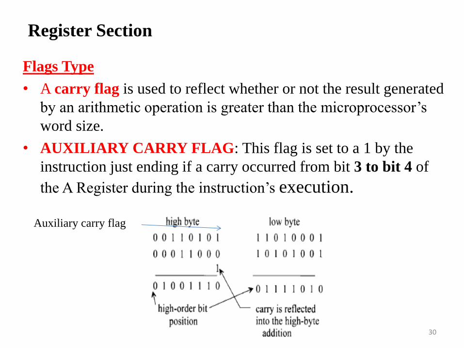
• A carry flag is used to reflect whether or not the result generated
by an arithmetic operation is greater than the microprocessor’s
word size.
• AUXILIARY CARRY FLAG: This flag is set to a 1 by the
instruction just ending if a carry occurred from bit 3 to bit 4 of
the A Register during the instruction’s execution.
Register Section
30
Auxiliary carry flag
Flags Type
• A zero flag is used to show whether the result of an
operation is zero. It is set to1 if the result is zero, and
it is reset to 0 if the result is nonzero.
• A parity flag is set to 1 to indicate whether the result
of the last operation contains either an even number
of 1’s (even parity) or an odd number of 1’s (odd
parity), depending on the microprocessor.
Register Section
31
Flags Type
• A sign flag (sometimes called a negative flag) is used to indicate whether the result of the last operation is positive(set to 0) or negative(set to 1)
• Overflow flag arises from representation of the sign flag by the most significant bit of a word in signed binary operation. The overflow flag is set to1 if the result of an arithmetic operation is too big for the microprocessor’s maximum word size, otherwise it is reset to 0
Register Section
32

EXAMPLE :
• Find the sign, carry, zero, overflow, and parity even
flag for the following arithmetic sign number:
(11110000) +(10100001) =10010001
SF =1 ,CF=1 ,ZF=0 ,OF=0 ,PF=0
Register Section
33
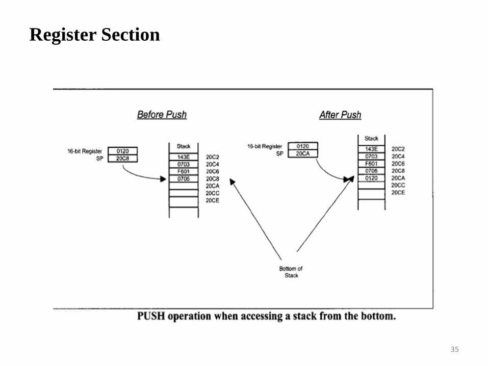
• Stack Pointer Register A stack consists of a number
of RAM locations set aside for reading data from or
writing data into these locations and is typically used
by subroutines
• Two instructions, PUSH and POP, are usually
available with a stack. The PUSH operation
is defined as writing to the top or bottom of the stack,
whereas the POP operation means reading from the
top or bottom of the stack.
Register Section
34
Register Section
35

Register Section
36

Register Section
37

Register Section
38

• The main purpose of the control unit is to read and
decode instructions from the program memory.
• To execute an instruction, the control unit steps
through the appropriate blocks of the ALU based on
the op-codes contained in the instruction register.
Control Unit
39
Control Signal Actions
• RESET. This input is common to all
microprocessors. When this input pin is driven HIGH
or LOW (depending on the microprocessor), the
program counter is loaded with a predefined address
specified by the manufacturer.
Control Unit
40
Control Signal Actions
• READ/WRITE (R/W) This output line is common to
all microprocessors. The status of this line tells the other
microcomputer elements whether the microprocessor is
performing a READ or a WRITE operation. A HIGH
signal on this line indicates a READ operation, and a
LOW indicates a WRITE operation.
Control Unit
41
Control Signal Actions
• READY, This is an input to a microprocessor. Slow devices (memory and I/O) use this signal to gain extra time to transfer data to or receive data from a microprocessor. The READY signal is usually an active low signal; that is, LOW indicates that the microprocessor is ready. Therefore, when the microprocessor selects a slow device, the device places a LOW on the READY pin.
• The microprocessor responds by suspending all its internal operations and enters a WAIT state. When the device is ready to send or receive data, it removes the READY signal. The microprocessor comes out of the WAIT state and performs the appropriate operation.
Control Unit
42
Control Signal Actions
• Interrupt Request (INT or IRQ). The external I/O
devices can interrupt the microprocessor via this input pin on the
microprocessor chip. When this signal is activated by the external
devices, the microprocessor jumps to a special program called the
interrupt service routine. This program is normally written by the
user for performing tasks that the interrupting device wants the
microprocessor to carry out. After completing this program, the
microprocessor returns to the main program it was executing when
the interrupt occurred.
Control Unit
43
• The ALU performs all the data manipulations, such as
arithmetic and logic operations, inside a
microprocessor. The size of the ALU conforms to the
word length of the microcomputer.
• ALU Functions:
1.Binary addition and logic operations
2. Finding the one’s complement of data
3. Shifting or rotating the contents of a general-
purpose register 1 bit to the left or right through a
carry
Arithmetic-Logic Unit
44
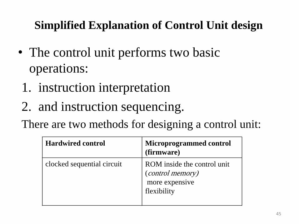
• The control unit performs two basic
operations:
1. instruction interpretation
2. and instruction sequencing.
There are two methods for designing a control unit:
Simplified Explanation of Control Unit design
45
Hardwired control
Microprogrammed control
(firmware)
clocked sequential circuit ROM inside the control unit
(control memory)
more expensive
flexibility
Simplified Explanation of Control Unit design
• Hard Wired Control Unit The Cycles or Phases
(Fetch, Indirect, Execute, Interrupt) are constructed as
a State Machine
• The Individual instruction executions can be
constructed as State Machines
– Common sections can be shared. There is a lot of
similarity
• One ALU is implemented. All instructions share it
46
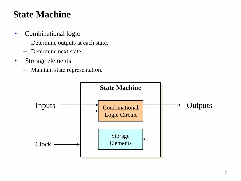
State Machine
• Combinational logic
– Determine outputs at each state.
– Determine next state.
• Storage elements
– Maintain state representation.
State Machine
Combinational
Logic Circuit
Storage
Elements
Inputs Outputs
Clock
47
Problems With Hard Wired Designs
• Sequencing & micro-operation logic gets complex
• Difficult to design, prototype, and test
• Resultant design is inflexible, and difficult to build upon
(Pipeline, multiple computation units, etc.)
• Adding new instructions requires major design and adds
complexity quickly
48
Control Unit : Organization Microprogrammed
control
• The Control Memory contains sequences of microinstructions that provide
the control signals to execute instruction cycles, e.g. Fetch, Indirect,
Execute, and Interrupt.
Horizontal Micro-programming:
• Wide control memory word
• High degree of parallel operations possible
• Little encoding of control information
• Fast
Vertical Micro-programming :
• Width can be much narrower
• Control signals encoded into function codes – need to be decoded
• More complex, more complicated to program, less flexibility
• More difficult to modify
• Slower
49
• The following three steps for completing the instruction:
1.Fetch. The microprocessor fetches (instruction read) the
instruction from the main memory (external to the
microprocessor) into the instruction register.
2. Decode. The microprocessor decodes or translates the
instruction using the control unit. The control unit inputs the
contents of the instruction register, and then decodes
(translates) the instruction to determine the instruction type.
3. Execute. The microprocessor executes the instruction using the
control unit. To accomplish the task, the control unit generates
a number of enable signals required by the instruction.
Program Execution by Conventional Microprocessors
50
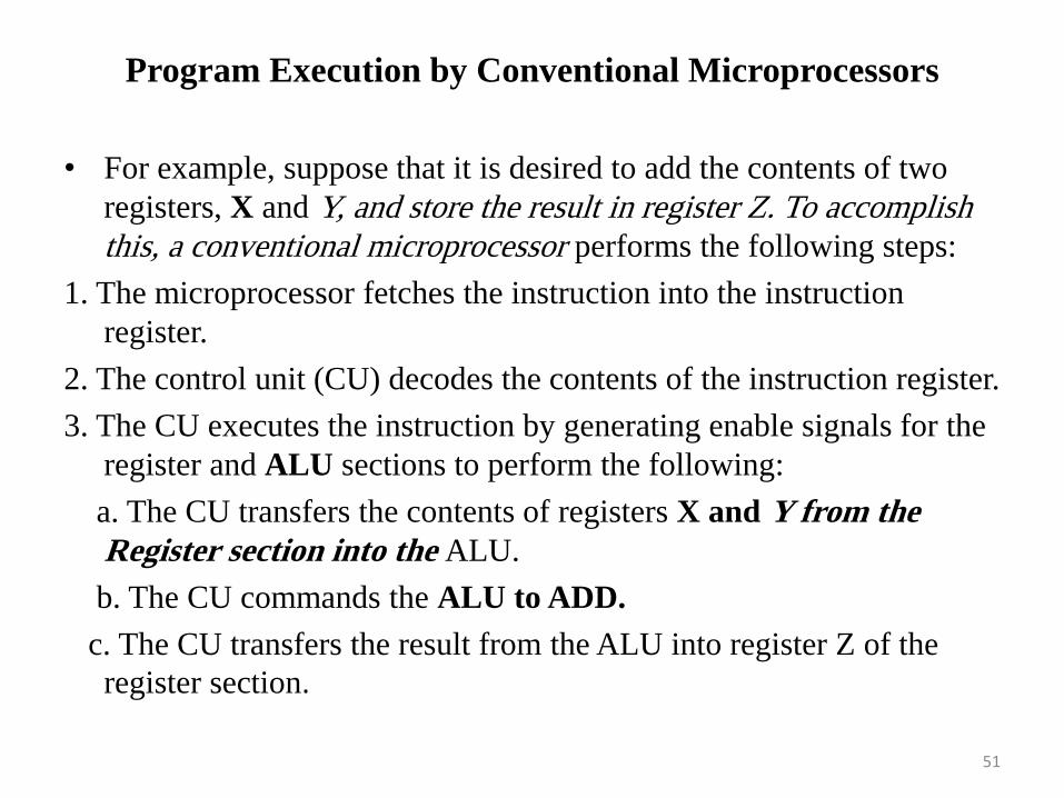
• For example, suppose that it is desired to add the contents of two
registers, X and Y, and store the result in register Z. To accomplish
this, a conventional microprocessor performs the following steps:
1. The microprocessor fetches the instruction into the instruction
register.
2. The control unit (CU) decodes the contents of the instruction register.
3. The CU executes the instruction by generating enable signals for the
register and ALU sections to perform the following:
a. The CU transfers the contents of registers X and Y from the
Register section into the ALU.
b. The CU commands the ALU to ADD.
c. The CU transfers the result from the ALU into register Z of the
register section.
Program Execution by Conventional Microprocessors
51

• Enhancement in 32-bit microprocessors (like
Pentium) include : cache memory, memory
management, pipelining, floating-point
arithmetic, and branch prediction.
• Cache memory is a high-speed read/write
memory implemented as on-chip
hardware in typical 32-bit microprocessors in
order to increase processing rates. This topic
is covered in more detail in Chapter 3.
Program Execution by typical 32-bit Microprocessors
52
• Memory management
allows programmers to write programs much larger than
those that could fit in the main memory space available
to the microprocessors; the programs are simply stored
on a secondary device, such as a hard disk.
This topic is covered in more detail in Chapter 3.
53
Program Execution by typical 32-bit Microprocessors
Pipeline
• One way to speed up CPU is to increase clock rate
– limitations on how fast clock can run to complete instruction
• Another way is to execute more than one instruction at one time
• Pipelining breaks instruction execution down into several stages
– put registers between stages to “buffer” data and control
– execute one instruction
– as first starts second stage, execute second instruction, etc.
– speedup same as number of stages as long as pipe is full
54

• Example of the execution of a stream of five
instructions: 11,12,13,14, and 15, in which I3 is a
conditional branch instruction.
Pipelining
55

• This allows these microprocessors to anticipate jumps of the instruction flow ahead of time.
• To accomplish this, the Pentium includes on-chip hardware called the Branch Unit (BU).
• The BU contains the branch execution unit (BEU) and the branch prediction unit (BPU). Whenever the Pentium encounters a conditional branch instruction, it sends it to the BU for execution.
• The BU evaluates the instruction’s branch condition using the BEU and determines whether the branch should or should not be taken.
• Once the BU determines the branch condition, it calculates the starting address (Branch target) of the next block of code to be executed. The Pentium then starts fetching code at the new address.
Branch Prediction Feature
56
• Scalar processors such as the 80486 can execute one
instruction per cycle. The 80486 contains only one pipeline.
• Superscalar microprocessors, can execute
more than one instruction per cycle. These microprocessors contain more than one pipeline.
• Superscalar machines issue a variable number of • instructions each clock cycle, up to some maximum
– instructions must satisfy some criteria of – independence
• The Pentium, a superscalar microprocessor, contains two independent pipelines. This
allows the Pentium to execute two instructions per cycle.
Scalar and Superscalar Microprocessors
57
• There are two types of microprocessor architectures: RISC and CISC.
• RISC stand for (reduced instruction set computer) and CISC for (complex instruction set computer).
RISC Characteristics
• One instruction per cycle
• Register to register operations
• Few, simple addressing modes
• Few, simple instruction formats
• Hardwired design (no microcode)
• Fixed instruction format
• More compile time/effort
Microprocessor architectures RISC vs. CISC
58

Why CISC?
• Compiler simplification?
– Complex machine instructions harder to exploit
• Smaller programs?
– Program takes up less memory but…
– Memory is now cheap
– May not occupy less bits, just look shorter in
symbolic form
• More instructions require longer op-codes
• Register references require fewer bits
59
Microprocessor Data Types - x86 Data Types
• 8 bit Byte
• 16 bit word
• 32 bit double word
• 64 bit quad word
• 128 bit double quadword
• Addressing is by 8 bit unit
• Words do not need to align at even-numbered address
• Data accessed across 32 bit bus in units of double word read at addresses divisible by 4
60
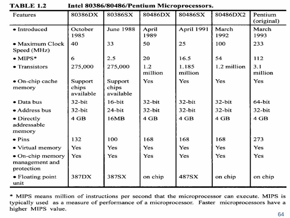
The Evolution of The Intel x86 Microprocessor
8080 :
first general purpose microprocessor
8 bit data path
Used in first personal computer
8086 : much more powerful
16 bit
instruction cache, prefetch few instructions
80286: This extension of the 8086 enabled addressing a 16-
MByte memory instead of just 1 MByte.
80386: Intel’s first 32-bit machine,
Support for multitasking
80486 :
sophisticated powerful cache and instruction pipelining
built in maths co-processor
61
Pentium Evolution
• Pentium
– Superscalar
– Multiple instructions executed in parallel
• Pentium Pro
– Increased superscalar organization
– Aggressive register renaming
– branch prediction
– data flow analysis
– speculative execution
62

Pentium Evolution
Pentium II
MMX technology
graphics, video & audio processing
basically takes attributes of the Pentium Pro processor
(designed for 32 bit OS) plus the capabilities of MMX
technology to yield processor speeds of 333, 300, 266, and 233
MHz.
MMX (matrix math extensions) is intended for efficient
multimedia and communications operations.
Pentium III:Additional floating point instructions for 3D graphics
Pentium 4 :Note Arabic rather than Roman numerals
Further floating point and multimedia enhancements
Itanium : 64 bit 63
64
Evolution of the Microprocessor
• All computer families have common Characteristics
– Similar or identical instruction sets.
– Similar or identical O/S.
– Increasing speed.
– Increasing number of I/O ports (i.e. more
terminals).
– Increased memory size.
– Increased cost.
65
That’s all for Today!!
Text Book:
• Computer Architecture A Quantitative
Approach (Chapter 1)
COMPUTER ORGANIZATION AND ARCHITECTURE
(Chapter 12, 13)
66