Embed Size (px)
Citation preview
Doc No: IM – 53 Rev. 0.0 Print: Sept’ 2008
MAINTENANCE INSTRUCTION
MANUAL
MICROPROCESSOR BASED
LOCOMOTIVE CONTROL SYSTEM
MEP 660
FOR DIESEL ELECTRIC LOCOMOTIVES
As Per
RDSO Specification No. MP.0.24.00.26 Rev.0.04
May, 2007
P- 4 / 5 B, I.D.A NACHARAM HYDERABAD 500 076
Ph. No. 040- 2717 3990 Fax. 040 2717 4908 Email: [email protected] URL: www.medhaindia.com
Doc No. :IM 53 Rev. 0.0 Print: Sept’ 2008
MEP-660 – Maintananace Instructions
INDEX SHEET
1. Introduction 1
2. Circuit Description 2
3. Control Unit TYPE MEP 660 2
3.1. Control Card MEP_CC 3
3.2. Control Card MAU_CC 4
3.3. Control Card MWS_CC 5
3.4. Digital Input Card MDIP16 / MIDIP16 5
3.5. Digital Output Cards 6
3.5.1. Medha High Side drive Card MHSD16 / MIHSD16 6
3.5.2. Medha Low Side drive Card MLSD16 6
3.6. Analog Input Cards 7
3.6.1. Medha Analog Input card MAIP8_AU 7
3.6.2. Medha Analog Input Card MAIP8_WS 8
3.6.3. Medha Analog Input card MAIP8_EP 8
3.6.4. Medha Improved Analog Input card MAIP16 / MIAI 8
3.7. Medha Frequency Input Card MFIP16 8
3.8. Medha Pulse Width Modulator Card MPWM2 9
3.9. Medha Excitation and Propulsion Power Supply Card MEPPS 9
3.10. Medha Display Unit MDS 733 10
3.11. Analog Distribution Box (ADB) MDB 701 11
3.12. RPM Distribution Box (RDB) TYPE MDB 702 12
4. Current Sensors 13
4.1. Medha Current Sensor MCS 850 13
4.2. Medha Current Sensor MCS 820 13
4.3. Medha Current Sensor MCS 803 14
4.4. Medha Current Sensor MCS 10A 14
5. Voltage Sensors 14
5.1. Medha Voltage Sensor MVS 815 15
5.2. Medha Voltage Sensor MVS 801 15
Doc No. :IM 53 Rev. 0.0 Print: Sept’ 2008
MEP-660 – Maintananace Instructions
6. Temperature Sensors 15
6.1. Medha Temperature Sensor MTS 815A 16
6.2. Medha Temperature Sensor MTS 815L 16
6.3. Medha Temperature Sensor MTS 815W 16
7. Pressure Sensors 17
7.1. Medha Pressure Sensor MPS 841 17
7.2. Medha Pressure Sensor MPS 842 17
7.3. Medha Pressure Sensor MPS-844 17
7.4. Medha Pressure Sensor MPS-845 17
7.5. Medha Pressure Sensor MPS-846 17
7.6. Altitude Sensor MPS 843 17
8. Speed Sensors 18
8.1. Tr. Motor Speed Sensor T815 18
8.2. Engine Speed Sensor T817 19
9. Resistor Unit Type - MRP 703 20
10. Ancillary Units 22
10.1. CGR/PGR Resistor unit MRP706 22
10.2. Memory Freeze cum VCD Disable UNIT MMF 705 23
10.3. XD23-XC13 Assembly unit 24
10.4. Motor Cut Out Switch Box MSP 707 25
10.5. Speed Sensor Interface Unit MSI 761 26
10.6. FCP Panel 27
10.7. HLD Relay Module MRA 710 28
10.8. VCD Magnet valve 29
Doc No. :IM 53 Rev. 0.0 Print: Sept’ 2008
MEP-660 – Maintananace Instructions
List of Annexure
1. Interconnection diagram of all MEP components Annexure – 1 2. Interconnection diagram of all cards in MEP Annexure – 2 3. List of digital input cards - channel wise Annexure – 3 4. Manual digital input check procedure through Disp. Unit Annexure – 4 5. List of digital output cards - channel wise. Annexure – 5 6. Manual digital output check procedure through Disp. Unit Annexure – 6 7. List of analog inputs Annexure -- 7 8. Crimping tool & connector pin details Annexure – 8
Doc No. :IM 53 Rev. 0.0 Print: Sept’ 2008 1
MEP-660 – Maintananace Instructions
1. INTRODUCTION
The Diesel Electric Locomotives of Indian Railways, driven by DC traction motors, employ AC/DC Power Transmission System. The MEP-660 Medha Excitation and Propulsion system is a Microprocessor Based Locomotive Control System. The system provides a superior control mechanism, protection to traction equipment, fault diagnostics, and adaptability to different engine types. The Microprocessor based Locomotive Control System Type MEP-660 control the entire locomotive. There are four-sub control systems like
• Engine and loco propulsion • Auxiliary generator / Battery charging
• Excitation.
• Wheel Slip control There are no mechanical sequential interlocks between inputs and output devices of the engine cranking and loco propulsion system. As per the operational requests by the driver, the MEP-660 directly energies the required output devices. The sequential / safety interlocking and the required timings are provided through software which is loaded in the micro controller. The Microprocessor based Locomotive Control System MEP 660 continuously monitors the train line signals (MU signals) and controls the excitation of the Alternator based on the operating requests of the Driver. It monitors various analog and digital feedback signals from the traction equipment and controls the excitation in such a way as to maintain constant Horse Power of the Diesel Engine. The MEP 660 system controls the excitation of the Auxiliary Generator so as to maintain constant output voltage for Battery Charging as well as control circuits in spite of variation in the engine speed from Idle to the 8th notch. Being a Microprocessor based system; the MEP 660 has Fault Diagnostic capabilities. The System continuously monitors various operational parameters and checks for abnormalities in the functioning of various traction equipments. In case a fault is identified, an appropriate action by way of isolating a sub system or limiting the power, etc is taken to prevent further damage to the equipment and other connected equipments. The fault is also displayed on a Display Unit along with the restrictions imposed because of fault, for the information of the Driver. The fault code along with Real Time and Date stamp is logged in the Error Log Memory. The MEP 660 Control System displays various operating parameters on the Display Unit continuously from the selected predefined groups for the benefit of the driver and maintenance staff. All the functions described above are implemented in the Microprocessor based Locomotive Control System MEP 660, which is designed with number of sub assemblies for ease of maintenance and reducing the amount of cabling required. The Microprocessor based Locomotive Control System MEP 660 consists of the following sub assemblies.
Control Unit Type MEP 660 Display Unit Type MDS 733 Analog Distribution Units Type MDB 701 RPM Distribution Unit Type MDB 702 Current Sensors Type MCS xxx Voltage Sensors Type MVS 8xx
Doc No. :IM 53 Rev. 0.0 Print: Sept’ 2008 2
MEP-660 – Maintananace Instructions
Temperature Sensors Type MTS 815x Pressure Sensors Type MPS 8xx Altitude Sensors Type MPS 843 Speed Sensors Type T815/T817 Resister Unit Type MRP 703 XD23-XC13 assembly unit Type MDA 751 Memory Freeze cum / VCD Disable Type MMF 705 CGR/PGR Resistor unit Type MRP 706 Engine Speed Sensor Interface unit Type MSI 761 HLD Relay Module Type MRA 710 Field Control Panel (FCP) Type SFCP- 25 VCD Magnet Valve Type 3332-10-4G
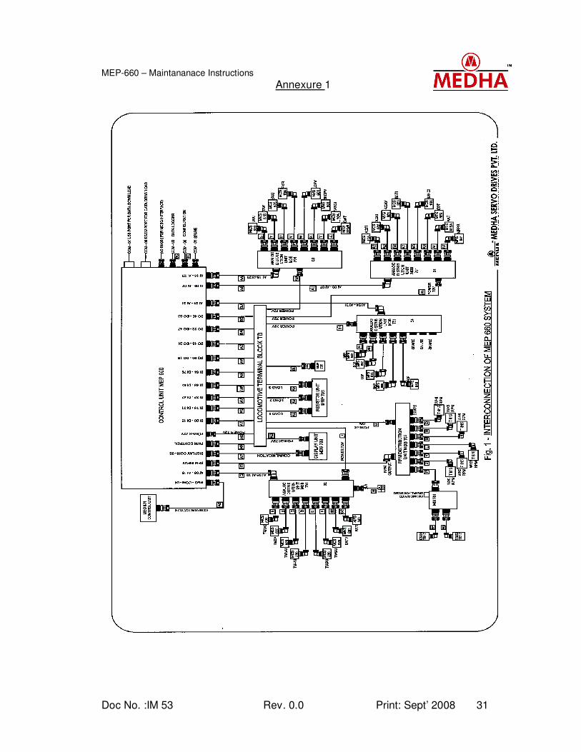
The Interconnection Diagram of all the above sub assemblies of MEP-660 is given in Annexure – 1. All these sub assemblies are interconnected through plug in type MS Connectors for ease of installation and maintenance. These sub assemblies are described below. Please refer the electrical schematics of Microprocessor based control system MEP-660, document No. ED100 or ED1001, for the details of individual connecting cables and their pin Numbers.
2. CIRCUIT DESCRIPTION
Please refer ‘Hand Manual’ on Microprocessor Based Loco Control system MEP-660, document No. IM 39 for detailed circuit explanation.
3. CONTROL UNIT TYPE MEP 660
Description: This is main control equipment of the Microprocessor system. The control unit consists 18+1(spare) plug in module type cards in dust proof enclosures. These modules are provided with proper identification number both on the module and as well on the control unit of each slot. The unit is engineered for quick replacement of any plug in card. These plug in cards are functionally separated in to modules of the main system. The backplane of the control unit is designed in such a way that insertion of a module can be done only at its earmarked position. The complete unit has a Transparent cover with a lock. The lock provides protection against unauthorized opening. With transparent cover, the indication LED’s provided on some of the individual modules can be seen from outside. These LED’s can give information about the status of various signal inputs as well as proper functioning of the concerned modules. Please refer ‘System Manual’ of Microprocessor based loco control system MEP-660, document No. IM 08, for Dimensional Drawing and mounting details of the control Unit. All the external connections to this control unit are done through MS circular connectors. These connectors are earmarked and similar identification markings are provided on the cables, which are connected, to these connectors. These connectors are also polarized to avoid wrong insertion of connectors in service. The block diagram of interconnections of all these modules through the back plane is given in Annexure – 2 Maintenance: There are no user serviceable components available in the control unit base. The connectors are wired to the back plane PCB directly. No preventive maintenance is required to the base up to M48 schedule as there are no passive components in the base unit. Only external blowing and cleaning of dust is required from M4 schedule onwards.
Doc No. :IM 53 Rev. 0.0 Print: Sept’ 2008 3
MEP-660 – Maintananace Instructions
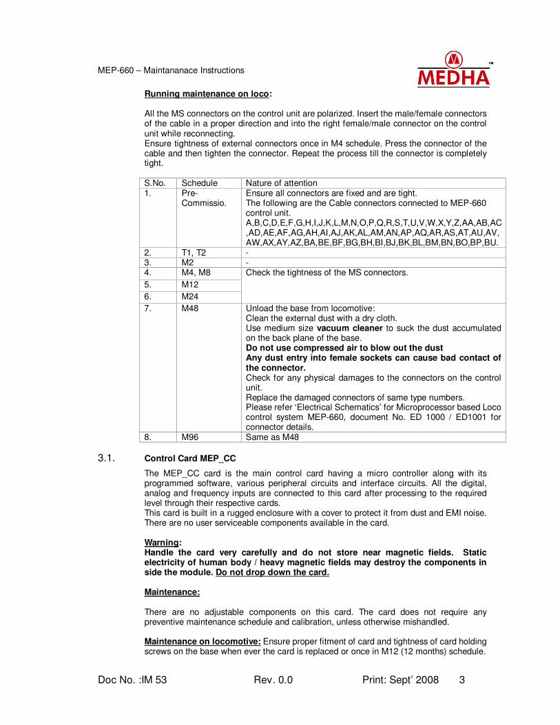
Running maintenance on loco: All the MS connectors on the control unit are polarized. Insert the male/female connectors of the cable in a proper direction and into the right female/male connector on the control unit while reconnecting. Ensure tightness of external connectors once in M4 schedule. Press the connector of the cable and then tighten the connector. Repeat the process till the connector is completely tight.
S.No. Schedule Nature of attention 1. Pre-
Commissio. Ensure all connectors are fixed and are tight. The following are the Cable connectors connected to MEP-660 control unit. A,B,C,D,E,F,G,H,I,J,K,L,M,N,O,P,Q,R,S,T,U,V,W,X,Y,Z,AA,AB,AC,AD,AE,AF,AG,AH,AI,AJ,AK,AL,AM,AN,AP,AQ,AR,AS,AT,AU,AV,AW,AX,AY,AZ,BA,BE,BF,BG,BH,BI,BJ,BK,BL,BM,BN,BO,BP,BU.
2. T1, T2 - 3. M2 - 4. M4, M8
5. M12
6. M24
Check the tightness of the MS connectors.
7. M48 Unload the base from locomotive: Clean the external dust with a dry cloth. Use medium size vacuum cleaner to suck the dust accumulated on the back plane of the base. Do not use compressed air to blow out the dust Any dust entry into female sockets can cause bad contact of the connector. Check for any physical damages to the connectors on the control unit. Replace the damaged connectors of same type numbers. Please refer ‘Electrical Schematics’ for Microprocessor based Loco control system MEP-660, document No. ED 1000 / ED1001 for connector details.
8. M96 Same as M48
3.1. Control Card MEP_CC
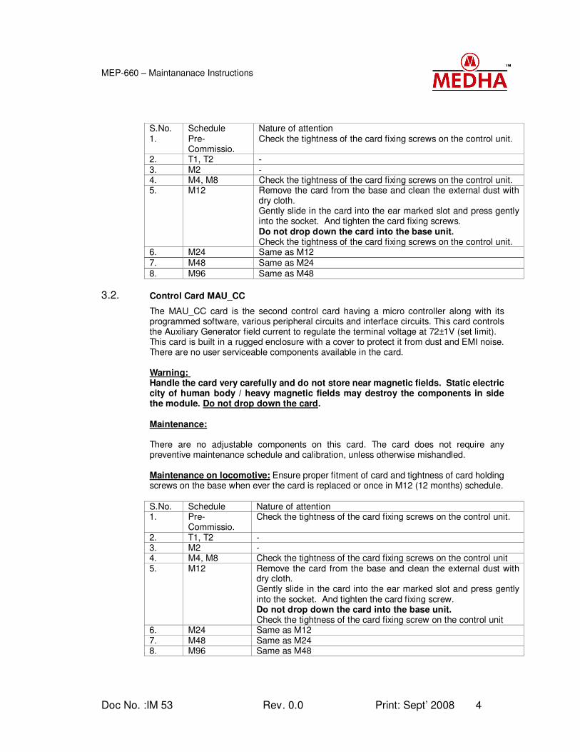
The MEP_CC card is the main control card having a micro controller along with its programmed software, various peripheral circuits and interface circuits. All the digital, analog and frequency inputs are connected to this card after processing to the required level through their respective cards. This card is built in a rugged enclosure with a cover to protect it from dust and EMI noise. There are no user serviceable components available in the card. Warning: Handle the card very carefully and do not store near magnetic fields. Static electricity of human body / heavy magnetic fields may destroy the components in side the module. Do not drop down the card. Maintenance: There are no adjustable components on this card. The card does not require any preventive maintenance schedule and calibration, unless otherwise mishandled. Maintenance on locomotive: Ensure proper fitment of card and tightness of card holding screws on the base when ever the card is replaced or once in M12 (12 months) schedule.
Doc No. :IM 53 Rev. 0.0 Print: Sept’ 2008 4
MEP-660 – Maintananace Instructions
S.No. Schedule Nature of attention 1. Pre-
Commissio. Check the tightness of the card fixing screws on the control unit.
2. T1, T2 - 3. M2 - 4. M4, M8 Check the tightness of the card fixing screws on the control unit. 5. M12 Remove the card from the base and clean the external dust with
dry cloth. Gently slide in the card into the ear marked slot and press gently into the socket. And tighten the card fixing screws. Do not drop down the card into the base unit. Check the tightness of the card fixing screws on the control unit.
6. M24 Same as M12 7. M48 Same as M24 8. M96 Same as M48
3.2. Control Card MAU_CC
The MAU_CC card is the second control card having a micro controller along with its programmed software, various peripheral circuits and interface circuits. This card controls the Auxiliary Generator field current to regulate the terminal voltage at 72±1V (set limit). This card is built in a rugged enclosure with a cover to protect it from dust and EMI noise. There are no user serviceable components available in the card. Warning: Handle the card very carefully and do not store near magnetic fields. Static electric city of human body / heavy magnetic fields may destroy the components in side the module. Do not drop down the card. Maintenance: There are no adjustable components on this card. The card does not require any preventive maintenance schedule and calibration, unless otherwise mishandled. Maintenance on locomotive: Ensure proper fitment of card and tightness of card holding screws on the base when ever the card is replaced or once in M12 (12 months) schedule.
S.No. Schedule Nature of attention 1. Pre-
Commissio. Check the tightness of the card fixing screws on the control unit.
2. T1, T2 - 3. M2 - 4. M4, M8 Check the tightness of the card fixing screws on the control unit 5. M12 Remove the card from the base and clean the external dust with
dry cloth. Gently slide in the card into the ear marked slot and press gently into the socket. And tighten the card fixing screw. Do not drop down the card into the base unit. Check the tightness of the card fixing screw on the control unit
6. M24 Same as M12 7. M48 Same as M24 8. M96 Same as M48
Doc No. :IM 53 Rev. 0.0 Print: Sept’ 2008 5
MEP-660 – Maintananace Instructions
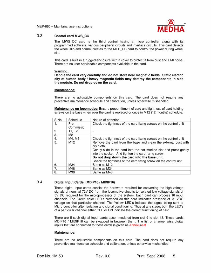
3.3. Control card MWS_CC
The MWS_CC card is the third control having a micro controller along with its programmed software, various peripheral circuits and interface circuits. This card detects the wheel slip and communicates to the MEP_CC card to control the power during wheel slip. This card is built in a rugged enclosure with a cover to protect it from dust and EMI noise. There are no user serviceable components available in the card. Warning: Handle the card very carefully and do not store near magnetic fields. Static electric city of human body / heavy magnetic fields may destroy the components in side the module. Do not drop down the card. Maintenance: There are no adjustable components on this card. The card does not require any preventive maintenance schedule and calibration, unless otherwise mishandled. Maintenance on locomotive: Ensure proper fitment of card and tightness of card holding screws on the base when ever the card is replaced or once in M12 (12 months) schedule.
S.No. Schedule Nature of attention 1. Pre-
Commissio. Check the tightness of the card fixing screws on the control unit
2. T1, T2 - 3. M2 - 4. M4, M8 Check the tightness of the card fixing screws on the control unit 5. M12 Remove the card from the base and clean the external dust with
dry cloth. Gently slide in the card into the ear marked slot and press gently into the socket. And tighten the card fixing screw. Do not drop down the card into the base unit. Check the tightness of the card fixing screw on the control unit
6. M24 Same as M12 7. M48 Same as M24 8. M96 Same as M48
3.4. Digital Input Cards (MDIP16 / MIDIP16)
These digital input cards consist the hardware required for converting the high voltage signals of nominal 72V DC from the locomotive circuits to isolated low voltage signals of 5V DC required for the microprocessor of the system. Each card can process 16 input channels. The Green color LED’s provided on this card indicates presence of 72 VDC voltage on that particular channel. The Yellow LED’s indicate the signal being sent to Micro controller after isolation and signal conditioning. Thus at any stage, both the LED’s of a particular channel either OFF or ON indicate the correct functioning of card. There are 5 such digital input cards accommodated from slot 9 to slot 13. These cards MDIP16 / MIDIP16 can be swapped in between them. The list of channel wise digital inputs that are connected to these cards is given as Annexure-3 Maintenance: There are no adjustable components on this card. The card does not require any preventive maintenance schedule and calibration, unless otherwise mishandled.
Doc No. :IM 53 Rev. 0.0 Print: Sept’ 2008 6
MEP-660 – Maintananace Instructions
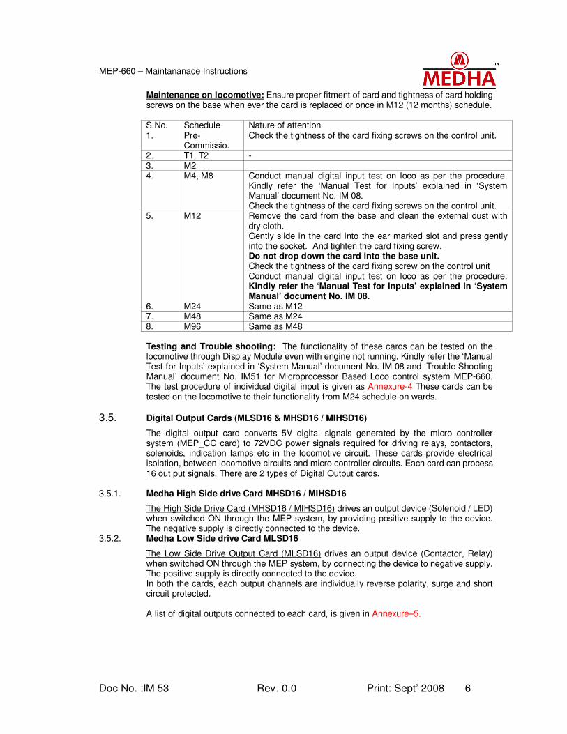
Maintenance on locomotive: Ensure proper fitment of card and tightness of card holding screws on the base when ever the card is replaced or once in M12 (12 months) schedule. S.No. Schedule Nature of attention 1. Pre-
Commissio. Check the tightness of the card fixing screws on the control unit.
2. T1, T2 - 3. M2 4. M4, M8 Conduct manual digital input test on loco as per the procedure.
Kindly refer the ‘Manual Test for Inputs’ explained in ‘System Manual’ document No. IM 08. Check the tightness of the card fixing screws on the control unit.
5. M12 Remove the card from the base and clean the external dust with dry cloth. Gently slide in the card into the ear marked slot and press gently into the socket. And tighten the card fixing screw. Do not drop down the card into the base unit. Check the tightness of the card fixing screw on the control unit Conduct manual digital input test on loco as per the procedure. Kindly refer the ‘Manual Test for Inputs’ explained in ‘System Manual’ document No. IM 08.
6. M24 Same as M12 7. M48 Same as M24 8. M96 Same as M48 Testing and Trouble shooting: The functionality of these cards can be tested on the locomotive through Display Module even with engine not running. Kindly refer the ‘Manual Test for Inputs’ explained in ‘System Manual’ document No. IM 08 and ‘Trouble Shooting Manual’ document No. IM51 for Microprocessor Based Loco control system MEP-660. The test procedure of individual digital input is given as Annexure-4 These cards can be tested on the locomotive to their functionality from M24 schedule on wards.
3.5. Digital Output Cards (MLSD16 & MHSD16 / MIHSD16)
The digital output card converts 5V digital signals generated by the micro controller system (MEP_CC card) to 72VDC power signals required for driving relays, contactors, solenoids, indication lamps etc in the locomotive circuit. These cards provide electrical isolation, between locomotive circuits and micro controller circuits. Each card can process 16 out put signals. There are 2 types of Digital Output cards.
3.5.1. Medha High Side drive Card MHSD16 / MIHSD16
The High Side Drive Card (MHSD16 / MIHSD16) drives an output device (Solenoid / LED) when switched ON through the MEP system, by providing positive supply to the device. The negative supply is directly connected to the device.
3.5.2. Medha Low Side drive Card MLSD16
The Low Side Drive Output Card (MLSD16) drives an output device (Contactor, Relay) when switched ON through the MEP system, by connecting the device to negative supply. The positive supply is directly connected to the device. In both the cards, each output channels are individually reverse polarity, surge and short circuit protected. A list of digital outputs connected to each card, is given in Annexure–5.
Doc No. :IM 53 Rev. 0.0 Print: Sept’ 2008 7
MEP-660 – Maintananace Instructions
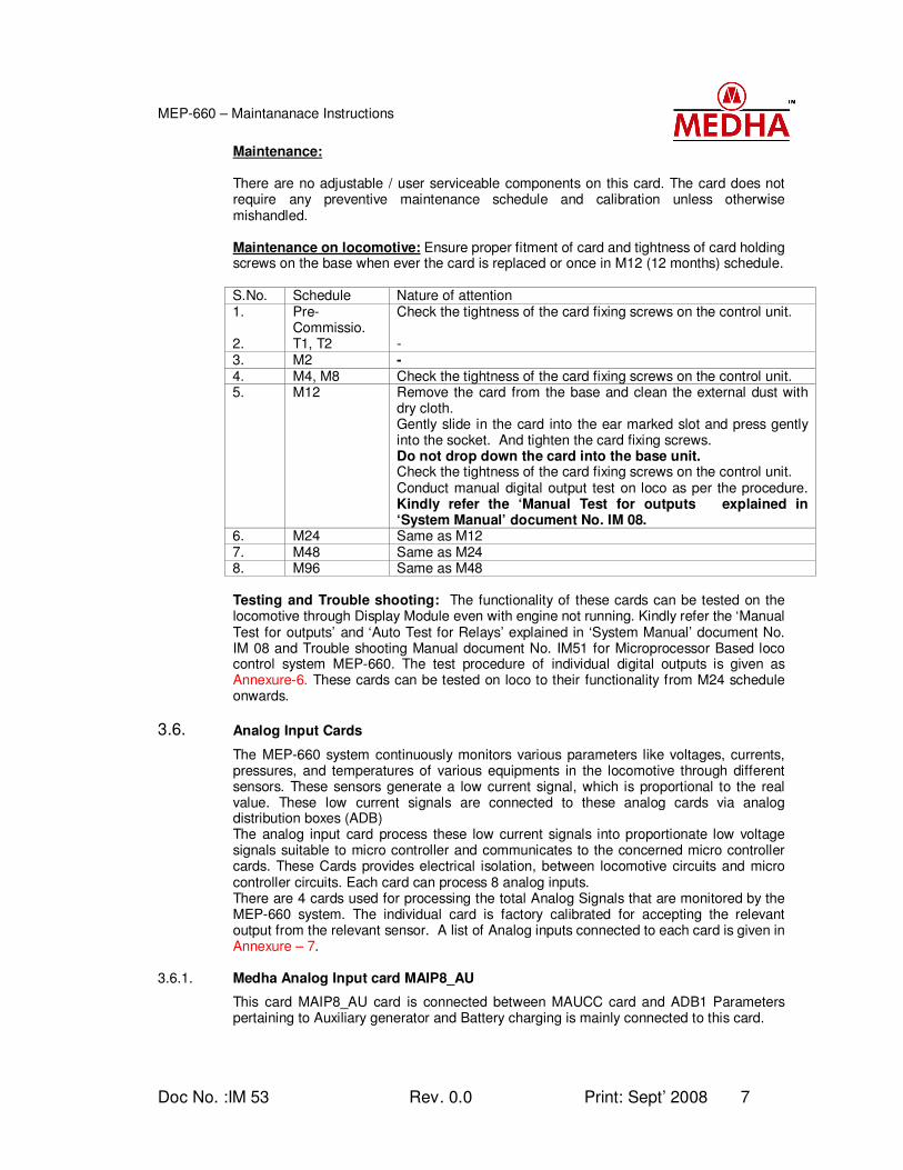
Maintenance: There are no adjustable / user serviceable components on this card. The card does not require any preventive maintenance schedule and calibration unless otherwise mishandled. Maintenance on locomotive: Ensure proper fitment of card and tightness of card holding screws on the base when ever the card is replaced or once in M12 (12 months) schedule. S.No. Schedule Nature of attention 1. Pre-
Commissio. Check the tightness of the card fixing screws on the control unit.
2. T1, T2 - 3. M2 - 4. M4, M8 Check the tightness of the card fixing screws on the control unit. 5. M12 Remove the card from the base and clean the external dust with
dry cloth. Gently slide in the card into the ear marked slot and press gently into the socket. And tighten the card fixing screws. Do not drop down the card into the base unit. Check the tightness of the card fixing screws on the control unit. Conduct manual digital output test on loco as per the procedure. Kindly refer the ‘Manual Test for outputs explained in ‘System Manual’ document No. IM 08.
6. M24 Same as M12 7. M48 Same as M24 8. M96 Same as M48 Testing and Trouble shooting: The functionality of these cards can be tested on the locomotive through Display Module even with engine not running. Kindly refer the ‘Manual Test for outputs’ and ‘Auto Test for Relays’ explained in ‘System Manual’ document No. IM 08 and Trouble shooting Manual document No. IM51 for Microprocessor Based loco control system MEP-660. The test procedure of individual digital outputs is given as Annexure-6. These cards can be tested on loco to their functionality from M24 schedule onwards.
3.6. Analog Input Cards
The MEP-660 system continuously monitors various parameters like voltages, currents, pressures, and temperatures of various equipments in the locomotive through different sensors. These sensors generate a low current signal, which is proportional to the real value. These low current signals are connected to these analog cards via analog distribution boxes (ADB) The analog input card process these low current signals into proportionate low voltage signals suitable to micro controller and communicates to the concerned micro controller cards. These Cards provides electrical isolation, between locomotive circuits and micro controller circuits. Each card can process 8 analog inputs. There are 4 cards used for processing the total Analog Signals that are monitored by the MEP-660 system. The individual card is factory calibrated for accepting the relevant output from the relevant sensor. A list of Analog inputs connected to each card is given in Annexure – 7.
3.6.1. Medha Analog Input card MAIP8_AU
This card MAIP8_AU card is connected between MAUCC card and ADB1 Parameters pertaining to Auxiliary generator and Battery charging is mainly connected to this card.
Doc No. :IM 53 Rev. 0.0 Print: Sept’ 2008 8
MEP-660 – Maintananace Instructions
3.6.2. Medha Analog Input Card MAIP8_WS
This card MAIP8_WS card is connected between MWS_CC card and ADB2 Individual traction motor current signals are mainly connected to this card.
3.6.3. Medha Analog Input card MAIP8_EP
This card MAIP8_EP card is connected between MEP_CC card and ADB3 All the excitation related parameters are mainly connected to this card.
3.6.4. Medha Improved Analog Input card MAIP16 / MIAI
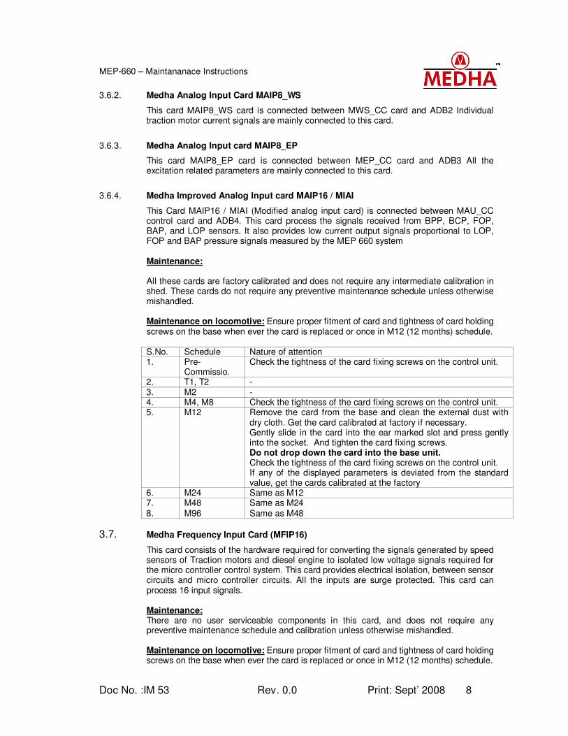
This Card MAIP16 / MIAI (Modified analog input card) is connected between MAU_CC control card and ADB4. This card process the signals received from BPP, BCP, FOP, BAP, and LOP sensors. It also provides low current output signals proportional to LOP, FOP and BAP pressure signals measured by the MEP 660 system
Maintenance: All these cards are factory calibrated and does not require any intermediate calibration in shed. These cards do not require any preventive maintenance schedule unless otherwise mishandled. Maintenance on locomotive: Ensure proper fitment of card and tightness of card holding screws on the base when ever the card is replaced or once in M12 (12 months) schedule. S.No. Schedule Nature of attention 1. Pre-
Commissio. Check the tightness of the card fixing screws on the control unit.
2. T1, T2 - 3. M2 - 4. M4, M8 Check the tightness of the card fixing screws on the control unit. 5. M12 Remove the card from the base and clean the external dust with
dry cloth. Get the card calibrated at factory if necessary. Gently slide in the card into the ear marked slot and press gently into the socket. And tighten the card fixing screws. Do not drop down the card into the base unit. Check the tightness of the card fixing screws on the control unit. If any of the displayed parameters is deviated from the standard value, get the cards calibrated at the factory
6. M24 Same as M12 7. M48 Same as M24 8. M96 Same as M48
3.7. Medha Frequency Input Card (MFIP16)
This card consists of the hardware required for converting the signals generated by speed sensors of Traction motors and diesel engine to isolated low voltage signals required for the micro controller control system. This card provides electrical isolation, between sensor circuits and micro controller circuits. All the inputs are surge protected. This card can process 16 input signals. Maintenance: There are no user serviceable components in this card, and does not require any preventive maintenance schedule and calibration unless otherwise mishandled. Maintenance on locomotive: Ensure proper fitment of card and tightness of card holding screws on the base when ever the card is replaced or once in M12 (12 months) schedule.
Doc No. :IM 53 Rev. 0.0 Print: Sept’ 2008 9
MEP-660 – Maintananace Instructions
S.No. Schedule Nature of attention 1. Pre-
Commissio. Check the tightness of the card fixing screws on the control unit.
2. T1, T2 - 3. M2 - 4. M4, M8 Check the tightness of the card fixing screws on the control unit. 5. M12 Remove the card from the base and clean the external dust with
dry cloth. Gently slide in the card into the ear marked slot and press gently into the socket. And tighten the card fixing screws. Do not drop down the card into the base unit. Check the tightness of the card fixing screw on the control unit.
6. M24 Same as M12 7. M48 Same as M24 8. M96 Same as M48
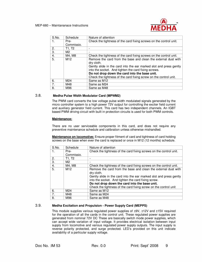
3.8. Medha Pulse Width Modulator Card (MPWM2)
The PWM card converts the low voltage pulse width modulated signals generated by the micro controller system to a high power 72V output for controlling the exciter field current and auxiliary generator field current. This card has two independent channels. An IGBT based PWM driving circuit with built in protection circuits is used for both PWM controls.
Maintenance: There are no user serviceable components in this card, and does not require any preventive maintenance schedule and calibration unless otherwise mishandled. Maintenance on locomotive: Ensure proper fitment of card and tightness of card holding screws on the base when ever the card is replaced or once in M12 (12 months) schedule. S.No. Schedule Nature of attention 1. Pre-
Commissio. Check the tightness of the card fixing screws on the control unit.
2. T1, T2 - 3. M2 - 4. M4, M8 Check the tightness of the card fixing screws on the control unit. 5. M12 Remove the card from the base and clean the external dust with
dry cloth. Gently slide in the card into the ear marked slot and press gently into the socket. And tighten the card fixing screw. Do not drop down the card into the base unit. Check the tightness of the card fixing screw on the control unit
6. M24 Same as M12 7. M48 Same as M24 8. M96 Same as M48
3.9. Medha Excitation and Propulsion - Power Supply Card (MEPPS)
This module supplies various regulated power supplies of ±9V, ±12V and ±15V required for the operation of all the cards in the control unit. These regulated power supplies are generated from nominal 72V DC These are basically switch mode power supplies, which can accept wide variation of input voltage. It provides electrical isolation between input supply from locomotive and various regulated power supply outputs. The input supply is reverse polarity protected, and surge protected. LED’s provided on this unit indicate availability of a particular supply voltage.
Doc No. :IM 53 Rev. 0.0 Print: Sept’ 2008 10
MEP-660 – Maintananace Instructions
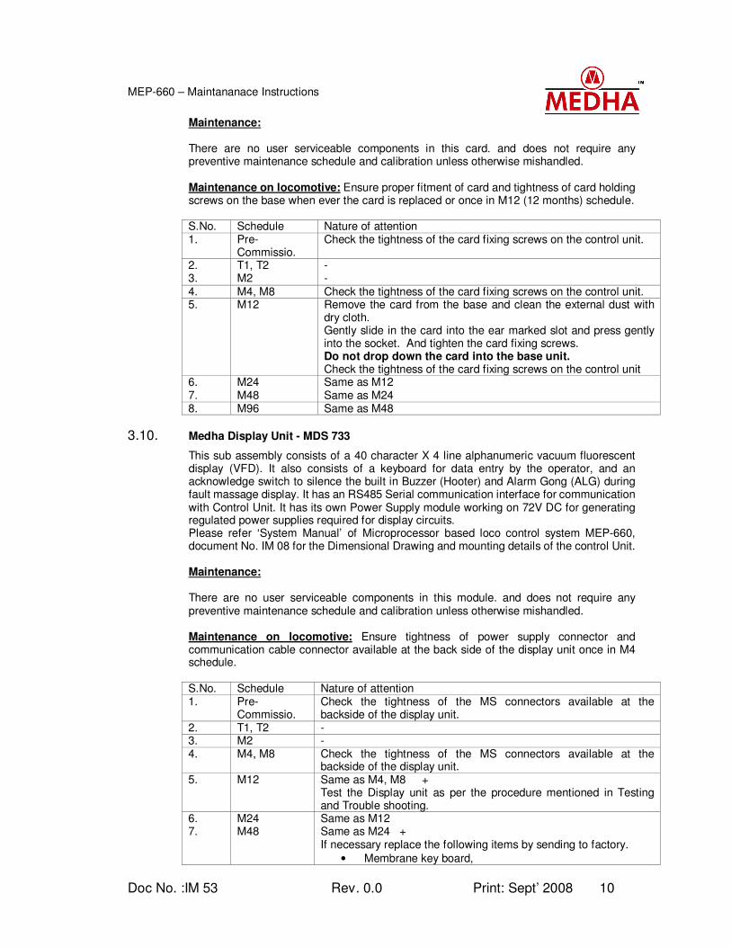
Maintenance: There are no user serviceable components in this card. and does not require any preventive maintenance schedule and calibration unless otherwise mishandled. Maintenance on locomotive: Ensure proper fitment of card and tightness of card holding screws on the base when ever the card is replaced or once in M12 (12 months) schedule. S.No. Schedule Nature of attention 1. Pre-
Commissio. Check the tightness of the card fixing screws on the control unit.
2. T1, T2 - 3. M2 - 4. M4, M8 Check the tightness of the card fixing screws on the control unit. 5. M12 Remove the card from the base and clean the external dust with
dry cloth. Gently slide in the card into the ear marked slot and press gently into the socket. And tighten the card fixing screws. Do not drop down the card into the base unit. Check the tightness of the card fixing screws on the control unit
6. M24 Same as M12 7. M48 Same as M24 8. M96 Same as M48
3.10. Medha Display Unit - MDS 733
This sub assembly consists of a 40 character X 4 line alphanumeric vacuum fluorescent display (VFD). It also consists of a keyboard for data entry by the operator, and an acknowledge switch to silence the built in Buzzer (Hooter) and Alarm Gong (ALG) during fault massage display. It has an RS485 Serial communication interface for communication with Control Unit. It has its own Power Supply module working on 72V DC for generating regulated power supplies required for display circuits. Please refer ‘System Manual’ of Microprocessor based loco control system MEP-660, document No. IM 08 for the Dimensional Drawing and mounting details of the control Unit. Maintenance: There are no user serviceable components in this module. and does not require any preventive maintenance schedule and calibration unless otherwise mishandled. Maintenance on locomotive: Ensure tightness of power supply connector and communication cable connector available at the back side of the display unit once in M4 schedule. S.No. Schedule Nature of attention 1. Pre-
Commissio. Check the tightness of the MS connectors available at the backside of the display unit.
2. T1, T2 - 3. M2 - 4. M4, M8 Check the tightness of the MS connectors available at the
backside of the display unit. 5. M12 Same as M4, M8 +
Test the Display unit as per the procedure mentioned in Testing and Trouble shooting.
6. M24 Same as M12 7. M48 Same as M24 +
If necessary replace the following items by sending to factory.
• Membrane key board,
Doc No. :IM 53 Rev. 0.0 Print: Sept’ 2008 11
MEP-660 – Maintananace Instructions
S.No. Schedule Nature of attention
• Acknowledge button,
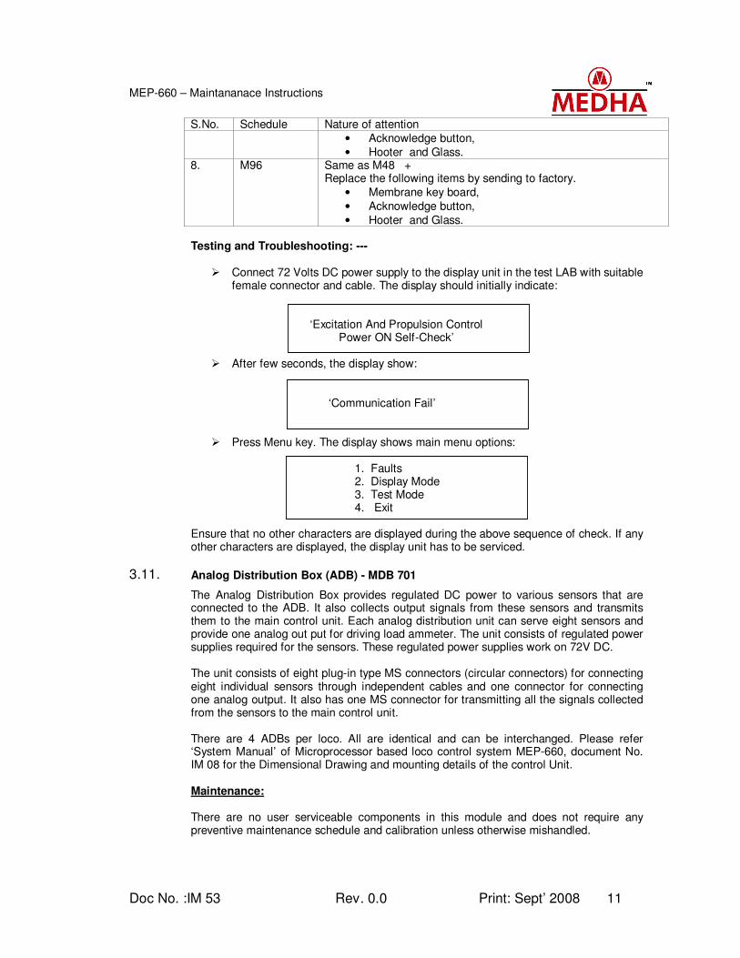
• Hooter and Glass. 8. M96 Same as M48 +
Replace the following items by sending to factory.
• Membrane key board,
• Acknowledge button,
• Hooter and Glass. Testing and Troubleshooting: ---
Connect 72 Volts DC power supply to the display unit in the test LAB with suitable female connector and cable. The display should initially indicate:
‘Excitation And Propulsion Control Power ON Self-Check’
After few seconds, the display show:
‘Communication Fail’
Press Menu key. The display shows main menu options:
1. Faults 2. Display Mode 3. Test Mode 4. Exit Ensure that no other characters are displayed during the above sequence of check. If any other characters are displayed, the display unit has to be serviced.
3.11. Analog Distribution Box (ADB) - MDB 701
The Analog Distribution Box provides regulated DC power to various sensors that are connected to the ADB. It also collects output signals from these sensors and transmits them to the main control unit. Each analog distribution unit can serve eight sensors and provide one analog out put for driving load ammeter. The unit consists of regulated power supplies required for the sensors. These regulated power supplies work on 72V DC. The unit consists of eight plug-in type MS connectors (circular connectors) for connecting eight individual sensors through independent cables and one connector for connecting one analog output. It also has one MS connector for transmitting all the signals collected from the sensors to the main control unit. There are 4 ADBs per loco. All are identical and can be interchanged. Please refer ‘System Manual’ of Microprocessor based loco control system MEP-660, document No. IM 08 for the Dimensional Drawing and mounting details of the control Unit. Maintenance: There are no user serviceable components in this module and does not require any preventive maintenance schedule and calibration unless otherwise mishandled.
Doc No. :IM 53 Rev. 0.0 Print: Sept’ 2008 12
MEP-660 – Maintananace Instructions
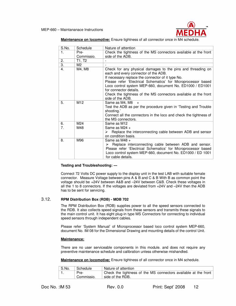
Maintenance on locomotive: Ensure tightness of all connector once in M4 schedule. S.No. Schedule Nature of attention 1. Pre-
Commissio. Check the tightness of the MS connectors available at the front side of the ADB.
2. T1, T2 - 3. M2 - 4. M4, M8 Check for any physical damages to the pins and threading on
each and every connector of the ADB. If necessary replace the connector of it type No. Please refer ‘Electrical Schematics’ for Microprocessor based Loco control system MEP-660, document No. ED1000 / ED1001 for connector details. Check the tightness of the MS connectors available at the front side of the ADB.
5. M12 Same as M4, M8 + Test the ADB as per the procedure given in ‘Testing and Trouble shooting.’ Connect all the connectors in the loco and check the tightness of the MS connectors.
6. M24 Same as M12 7. M48 Same as M24 +
Replace the interconnecting cable between ADB and sensor on condition basis.
8. M96 Same as M48 + Replace interconnecting cable between ADB and sensor. Please refer ‘Electrical Schematics’ for Microprocessor based Loco control system MEP-660, document No. ED1000 / ED 1001 for cable details.
Testing and Troubleshooting: --- Connect 72 Volts DC power supply to the display unit in the test LAB with suitable female connector. Measure Voltage between pins A & B and C & B With B as common point the voltage should be +24V between A&B and –24V between C&B. Check these voltages in all the 1 to 8 connectors. If the voltages are deviated from +24V and –24V then the ADB has to be sent for servicing.
3.12. RPM Distribution Box (RDB) - MDB 702
The RPM Distribution Box (RDB) supplies power to all the speed sensors connected to the RDB. It also collects speed signals from these sensors and transmits these signals to the main control unit. It has eight plug-in type MS Connectors for connecting to individual speed sensors through independent cables. Please refer ‘System Manual’ of Microprocessor based loco control system MEP-660, document No. IM 08 for the Dimensional Drawing and mounting details of the control Unit.
Maintenance: There are no user serviceable components in this module. and does not require any preventive maintenance schedule and calibration unless otherwise mishandled. Maintenance on locomotive: Ensure tightness of all connector once in M4 schedule. S.No. Schedule Nature of attention 1. Pre-
Commissio. Check the tightness of the MS connectors available at the front side of the RDB.
Doc No. :IM 53 Rev. 0.0 Print: Sept’ 2008 13
MEP-660 – Maintananace Instructions
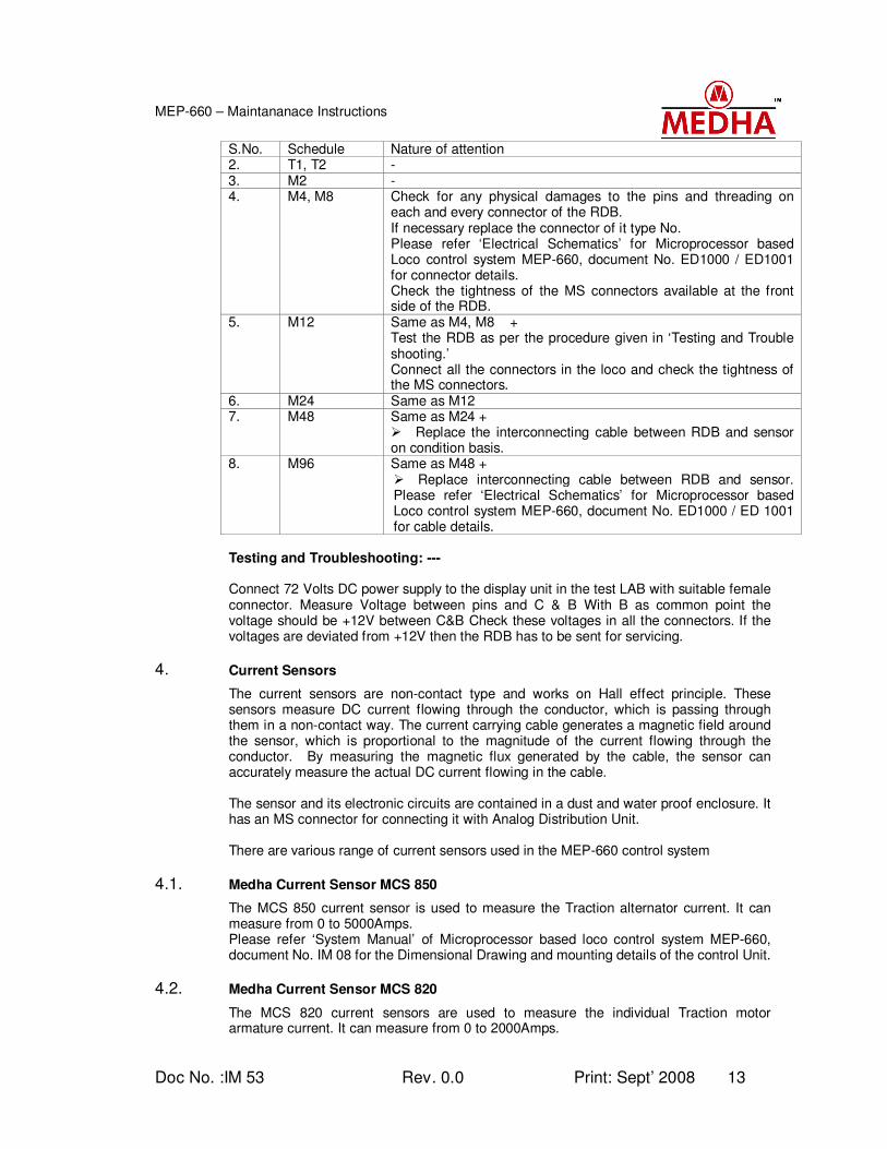
S.No. Schedule Nature of attention 2. T1, T2 - 3. M2 - 4. M4, M8 Check for any physical damages to the pins and threading on
each and every connector of the RDB. If necessary replace the connector of it type No. Please refer ‘Electrical Schematics’ for Microprocessor based Loco control system MEP-660, document No. ED1000 / ED1001 for connector details. Check the tightness of the MS connectors available at the front side of the RDB.
5. M12 Same as M4, M8 + Test the RDB as per the procedure given in ‘Testing and Trouble shooting.’ Connect all the connectors in the loco and check the tightness of the MS connectors.
6. M24 Same as M12 7. M48 Same as M24 +
Replace the interconnecting cable between RDB and sensor on condition basis.
8. M96 Same as M48 + Replace interconnecting cable between RDB and sensor. Please refer ‘Electrical Schematics’ for Microprocessor based Loco control system MEP-660, document No. ED1000 / ED 1001 for cable details.
Testing and Troubleshooting: --- Connect 72 Volts DC power supply to the display unit in the test LAB with suitable female connector. Measure Voltage between pins and C & B With B as common point the voltage should be +12V between C&B Check these voltages in all the connectors. If the voltages are deviated from +12V then the RDB has to be sent for servicing.
4. Current Sensors
The current sensors are non-contact type and works on Hall effect principle. These sensors measure DC current flowing through the conductor, which is passing through them in a non-contact way. The current carrying cable generates a magnetic field around the sensor, which is proportional to the magnitude of the current flowing through the conductor. By measuring the magnetic flux generated by the cable, the sensor can accurately measure the actual DC current flowing in the cable. The sensor and its electronic circuits are contained in a dust and water proof enclosure. It has an MS connector for connecting it with Analog Distribution Unit. There are various range of current sensors used in the MEP-660 control system
4.1. Medha Current Sensor MCS 850
The MCS 850 current sensor is used to measure the Traction alternator current. It can measure from 0 to 5000Amps. Please refer ‘System Manual’ of Microprocessor based loco control system MEP-660, document No. IM 08 for the Dimensional Drawing and mounting details of the control Unit.
4.2. Medha Current Sensor MCS 820
The MCS 820 current sensors are used to measure the individual Traction motor armature current. It can measure from 0 to 2000Amps.
Doc No. :IM 53 Rev. 0.0 Print: Sept’ 2008 14
MEP-660 – Maintananace Instructions
Please refer ‘System Manual’ of Microprocessor based loco control system MEP660, document No. IM 08 for the Dimensional Drawing and mounting details of the control Unit.
4.3. Medha Current Sensor MCS 803
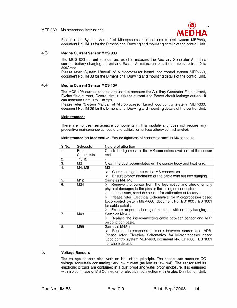
The MCS 803 current sensors are used to measure the Auxiliary Generator Armature current, battery charging current and Exciter Armature current. It can measure from 0 to 300Amps. Please refer ‘System Manual’ of Microprocessor based loco control system MEP-660, document No. IM 08 for the Dimensional Drawing and mounting details of the control Unit.
4.4. Medha Current Sensor MCS 10A
The MCS 10A current sensors are used to measure the Auxiliary Generator Field current, Exciter field current, Control circuit leakage current and Power circuit leakage current. It can measure from 0 to 10Amps. Please refer ‘System Manual’ of Microprocessor based loco control system MEP-660, document No. IM 08 for the Dimensional Drawing and mounting details of the control Unit. Maintenance: There are no user serviceable components in this module and does not require any preventive maintenance schedule and calibration unless otherwise mishandled. Maintenance on locomotive: Ensure tightness of connector once in M4 schedule. S.No. Schedule Nature of attention 1. Pre-
Commissio. Check the tightness of the MS connectors available at the sensor end.
2. T1, T2 - 3. M2 Clean the dust accumulated on the sensor body and heat sink. 4. M4, M8 M2 +
Check the tightness of the MS connectors. Ensure proper anchoring of the cable with out any hanging.
5. M12 Same as M4, M8 6. M24 Remove the sensor from the locomotive and check for any
physical damages to the pins or threading on connector. If necessary, send the sensor for calibration at factory. Please refer ‘Electrical Schematics’ for Microprocessor based Loco control system MEP-660, document No. ED1000 / ED 1001 for cable details. Ensure proper anchoring of the cable with out any hanging.
7. M48 Same as M24 + Replace the interconnecting cable between sensor and ADB on condition basis.
8. M96 Same as M48 + Replace interconnecting cable between sensor and ADB. Please refer ‘Electrical Schematics’ for Microprocessor based Loco control system MEP-660, document No. ED1000 / ED 1001 for cable details.
5. Voltage Sensors
The voltage sensors also work on Hall effect principle. The sensor can measure DC voltage accurately consuming very low current (as low as few mA). The sensor and its electronic circuits are contained in a dust proof and water proof enclosure. It is equipped with a plug in type of MS Connector for electrical connection with Analog Distribution Unit.

Doc No. :IM 53 Rev. 0.0 Print: Sept’ 2008 15
MEP-660 – Maintananace Instructions
5.1. Medha Voltage Sensor - MVS 815
The MVS 815 voltage sensor is used to measure Traction Alternator Voltage. It can measure from 0 to 1500Volts. Please refer ‘System Manual’ of Microprocessor based loco control system MEP-660, document No. IM 08, for the Dimensional Drawing and mounting details of the control Unit.
5.2. Medha Voltage Sensor - MVS 801
The MVS 801 voltage sensor is used to measure Battery voltage, Aux. Gen. Voltage, BKCP Voltage, LCP voltage. It can measure from 0 to 100Volts. Please refer ‘System Manual’ of Microprocessor based loco control system MEP-660, document No. IM 08 for the Dimensional Drawing and mounting details of the control Unit.
Maintenance: There are no user serviceable components in this module. and does not require any preventive maintenance schedule and calibration unless otherwise mishandled. Maintenance on locomotive: Ensure tightness of connector once in M4 schedule. S.No. Schedule Nature of attention 1. Pre-
Commissio. Check the tightness of the MS connectors available at the sensor end.
2. T1, T2 - 3. M2 Clean the dust accumulated on the sensor body and heat sink. 4. M4, M8 M2 +
Check the tightness of the MS connectors. Ensure proper anchoring of the cable with out any hanging.
5. M12 Same as M4, M8 6. M24 Remove the sensor from the locomotive and check for any
physical damages to the pins or threading on connector. If necessary, send the sensor for calibration at factory. Please refer ‘Electrical Schematics’ for Microprocessor based Loco control system MEP-660, document No. ED1000 / ED 1001 for cable details. Ensure proper anchoring of the cable with out any hanging.
7. M48 Same as M24 + Replace the interconnecting cable between sensor and ADB on condition basis.
8. M96 Same as M48 + Replace interconnecting cable between sensor and ADB. Please refer ‘Electrical Schematics’ for Microprocessor based Loco control system MEP-660, document No. ED1000 / ED 1001 for cable details.
6. Temperature Sensors
This is a semi conductor temperature sensor built in a rugged outer enclosure, which measures the temperature of the outer enclosure body. Different shapes of outer enclosures are used depending upon the application such as water temperature, lube oil temperature, air temperature etc. The sensor is equipped with a plug in type of MS connector for electrical connection with Analog Distribution Unit. It can measure the temperature from -50°C to + 150°C. Different mounting arrangements are provided depending upon the application.
Doc No. :IM 53 Rev. 0.0 Print: Sept’ 2008 16
MEP-660 – Maintananace Instructions
6.1. Medha Temperature Sensor MTS 815A
The model MTS 815A is used to measure the ambient air temperature mounted at the backside of the CP. Please refer ‘System Manual’ of Microprocessor based loco control system MEP-660, document No. IM 08 for the Dimensional Drawing and mounting details of the control Unit.
6.2. Medha Temperature Sensor MTS 815L
The model MTS 815L is used to measure the Lube oil temperature mounted on the lube oil pipeline in the expresser room. Please refer ‘System Manual’ of Microprocessor based loco control system MEP-660, document No. IM 08, for the Dimensional Drawing and mounting details of the control Unit.
6.3. Medha Temperature Sensor MTS815W
The model MTS 815W is used to measure the cooling temperature mounted on the water manifold pipeline near temperature gauge in the expresser room. Please refer ‘System Manual’ of Microprocessor based loco control system MEP-660, document No. IM 08 for the Dimensional Drawing and mounting details of the control Unit.
Maintenance: There are no user serviceable components in this module. and does not require any preventive maintenance schedule and calibration unless otherwise mishandled.
Maintenance on locomotive: Ensure tightness of connector once in M4 schedule.
S.No. Schedule Nature of attention 1. Pre-
Commissio. Check the tightness of the MS connectors available at the sensor end.
2. T1, T2 - 3. M2 Clean the dust accumulated on the sensor body and heat sink. 4. M4, M8 M2 +
Check the tightness of the MS connectors. Ensure proper anchoring of the cable with out any hanging.
5. M12 Same as M4, M8. 6. M24 Remove the sensor from the locomotive and check for any
physical damages to the pins or threading on connector. If necessary, send the sensor for calibration at factory. Please refer ‘Electrical Schematics’ for Microprocessor based Loco control system MEP-660, document No. ED1000 / ED 1001 for cable details. Ensure proper anchoring of the cable with out any hanging.
7. M48 Same as M24 + Replace the interconnecting cable between sensor and ADB on condition basis.
8. M96 Same as M48 + Replace interconnecting cable between sensor and ADB. Please refer ‘Electrical Schematics’ for Microprocessor based Loco control system MEP-660, document No. ED1000 / ED 1001 for cable details.
7. Pressure Sensors:
These are basically piezo-electric type sensors generating 4 to 20 mA out put. The body is made up of stainless steel construction and has a threaded mounting arrangement. The sensor is provided with a plug in type MS connector for electrical connection with Analog Distribution Unit.
Doc No. :IM 53 Rev. 0.0 Print: Sept’ 2008 17
MEP-660 – Maintananace Instructions
7.1. Medha Pressure Sensor MPS - 841
The pressure sensor of type No. MPS 841 is used to measure MR pressure in the locomotive to provide cut in and cut out limits for the electro pneumatic governor (EPG). It can measure from 0 to 21Kg/cm². Please refer ‘System Manual’ of Microprocessor based loco control system MEP-660, document No. IM 08 for mounting details and dimensional details of the Pressure sensor.
7.2. Medha Pressure Sensor MPS - 842
The pressure sensor of type No. MPS 842 is used to measure Brake Pipe Pressure (BPP) and Brake Cylinder Pressure (BCP) in the locomotive. It can measure from 0 to 14Kg/cm² Please refer ‘System Manual’ of Microprocessor based loco control system MEP-660, document No. IM 08 for mounting details and dimensional details of the Pressure sensor.
7.3. Medha Pressure Sensor MPS - 844
The pressure sensor of type No. MPS 844 is used to measure Lube Oil Pressure (LOP) in the locomotive. It can measure from 0 to 10Kg/cm². Please refer ‘System Manual’ of Microprocessor based loco control system MEP-660, document No. IM 08 for mounting details and dimensional details of the Pressure sensor.
7.4. Medha Pressure Sensor MPS- 845
The pressure sensor of type No. MPS 845 is used to measure Booster Air Pressure (BAP) in the locomotive. It can measure from 0 to 3.5Kg/cm². Please refer ‘System Manual’ of Microprocessor based loco control system MEP-660, document No. IM 08 for mounting details and dimensional details of the Pressure sensor.
7.5. Medha Pressure Sensor MPS- 846
The pressure sensor of type No. MPS 846 is used to measure Fuel Oil Pressure (FOP) in the locomotive. It can measure from 0 to 7kg/ cm². Please refer ‘System Manual’ of Microprocessor based loco control system MEP-660, document No. IM 08 for mounting details and dimensional details of the Pressure sensor.
7.6. Altitude Sensor MPS - 843
The Altitude sensor of type No. MPS 843 is used to dynamically measure altitude of the site where the locomotive is working. It can measure from 0 to 3000 meters from sea level. Please refer ‘System Manual’ of Microprocessor based loco control system MEP-660, document No. IM 08 for mounting details and dimensional details of the Pressure sensor. Maintenance: There are no user serviceable components in this module. and does not require any preventive maintenance schedule and calibration unless otherwise mishandled. Maintenance on locomotive: Ensure tightness of connector once in M4 schedule. S.No. Schedule Nature of attention 1. Pre-
Commissio. Check the tightness of the MS connectors available at the sensor end.
2. T1, T2 - 3. M2 Clean the dust accumulated on the sensor body and heat sink. 4. M4, M8 M2 +
Doc No. :IM 53 Rev. 0.0 Print: Sept’ 2008 18
MEP-660 – Maintananace Instructions
S.No. Schedule Nature of attention Check the tightness of the MS connectors. Ensure proper anchoring of the cable with out any hanging.
5. M12 Same as M4, M8. 6. M24 Remove the sensor from the locomotive and check for any
physical damages to the pins or threading on connector. If necessary, send the sensor for calibration at factory. Please refer ‘Electrical Schematics’ for Microprocessor based Loco control system MEP-660, document No. ED1000 / ED 1001 for cable details. Ensure proper anchoring of the cable with out any hanging.
7. M48 Same as M24 + Replace the interconnecting cable between sensor and ADB on condition basis.
8. M96 Same as M48 + Replace interconnecting cable between sensor and ADB. Please refer ‘Electrical Schematics’ for Microprocessor based Loco control system MEP-660, document No. ED1000 / ED 1001 for cable details.
8. Speed Sensors
The speed sensors are used to measure Tr. Motor speed and engine speeds. These sensors are Hall effect magnetic type sensors. These sensors are mounted over a rotating gear. The sensor generates one electric pulse for every teeth of the wheel and hence the signal frequency is proportional to the RPM of the gear over which the sensor is mounted.
8.1. Tr. Motor Speed Sensor - T815
T815 is a Hall effect magnetic sensors are used to measure the individual traction motor armature speed and from which the wheel RPM is calculated. The sensor is mounted on the Traction Motor end shield to measure the RPM of Traction Motor shaft with the help of a toothed wheel (like any gear wheel). The toothed wheel has been on to the armature shaft at the end of the CE bearing. The sensor is built in an rugged enclosure with a cable. The cable is coupled to the sensor cable coming from ADB available in the CP. The frequency output is 60 Hz if the Tr. Motor Armature rotates at 60RPM. Maintenance: There are no user serviceable components in the sensor module and does not require any preventive maintenance schedule unless otherwise mishandled.
Cleaning:
Blow out the dust accumulated on the sensor element and cable. Remove the Tr. Motor speed sensor from the Tr. Motor. Clean the sensor element and cable with a light cleaning solution to remove
oil and dirt. Clean the connectors and pins with a light cleaning solvent.
Inspection:
Check for any physical damages on the sensor tip. Check for any physical damages to the cable coming out of the sensor. Check the connector for proper locking with female socket. If the connector is
slack replace both Male and female connectors of the sensor cable.
Doc No. :IM 53 Rev. 0.0 Print: Sept’ 2008 19
MEP-660 – Maintananace Instructions
Please refer Annexure – 8 for type of connector and crimping tool required for replacement.
Maintenance on locomotive: S.No. Schedule Nature of attention 1. Pre-
Commissio. Check the tightness of the Bayonet connector available at the sensor top.
2. T1, T2 - 3. M2 Check the tightness of the MS connectors. Ensure proper
anchoring of the cable with out any hanging. Check the tightness of intermediate cable connectors at the anchoring bracket for the Traction motor speed sensor cables.
4. M4, M8 Same as M2 + Ensure tightness of Traction Motor speed sensor mounting screws on the Tr. Motor commutator end bearing end cup.
5 M12 Check the tightness of the MS connectors. Ensure proper anchoring of the cable with out any hanging. Check the tightness of intermediate cable connectors at the anchoring bracket for the Traction motor speed sensor cables. Ensure the sensor cable in intact with out any damage. Replace cable if damaged. Ensure tightness of Traction Motor speed sensor mounting screws on the Tr. Motor commutator end bearing end cup.
6. M24 Same as M12 7. M48 While the Tr. Motor is taken for over haul, remove the sensor
element from the Tr. Motor. Send the sensor for calibration at factory. Assemble the sensor on the overhauled traction motor. Replace the interconnecting cables from the sensors and RDB on condition basis.
8. M96 Same as M48 + Replace the interconnecting cables from the sensors and RDB. Please refer ‘Electrical Schematics’ for Microprocessor based Loco control system MEP-660, document No. ED1000 / ED 1001 for cable details.
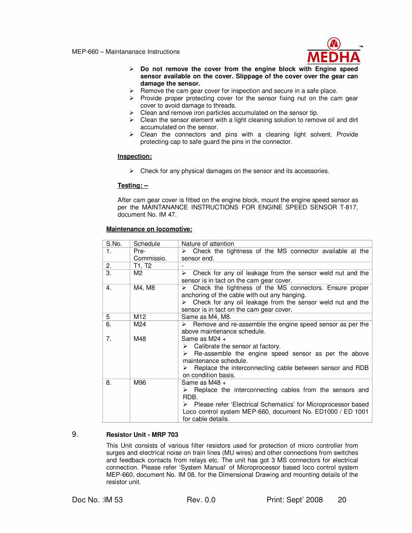
8.2. Engine Speed Sensor - T817
The Engine speed sensor T817 is also a hall effect magnetic sensor used for measuring the engine RPM. The sensor is mounting on the cam gear cover to measure the engine RPM. It generates one pulse for each teeth of the cam gear. As the cam gear is directly driven by the engine crankshaft, the pulses per second or frequency generated by the sensor is proportional to the engine RPM. Maintenance: There are no user serviceable components in the sensor module and does not require any preventive maintenance schedule and calibration unless otherwise mishandled.
Cleaning:
Blow out the dust accumulated on the sensor element. Remove the Engine speed sensor from cam gear cover while the cover is on
the engine block itself, as per the MAINTANANCE INSTRUCTIONS FOR ENGINE SPEED SENSOR T-817, document No. IM 47.
Doc No. :IM 53 Rev. 0.0 Print: Sept’ 2008 20
MEP-660 – Maintananace Instructions
Do not remove the cover from the engine block with Engine speed sensor available on the cover. Slippage of the cover over the gear can damage the sensor.
Remove the cam gear cover for inspection and secure in a safe place. Provide proper protecting cover for the sensor fixing nut on the cam gear
cover to avoid damage to threads. Clean and remove iron particles accumulated on the sensor tip. Clean the sensor element with a light cleaning solution to remove oil and dirt
accumulated on the sensor. Clean the connectors and pins with a cleaning light solvent. Provide
protecting cap to safe guard the pins in the connector.
Inspection:
Check for any physical damages on the sensor and its accessories.
Testing: --
After cam gear cover is fitted on the engine block, mount the engine speed sensor as per the MAINTANANCE INSTRUCTIONS FOR ENGINE SPEED SENSOR T-817, document No. IM 47.
Maintenance on locomotive: S.No. Schedule Nature of attention 1. Pre-
Commissio. Check the tightness of the MS connector available at the sensor end.
2. T1, T2 - 3. M2 Check for any oil leakage from the sensor weld nut and the
sensor is in tact on the cam gear cover. 4. M4, M8 Check the tightness of the MS connectors. Ensure proper
anchoring of the cable with out any hanging. Check for any oil leakage from the sensor weld nut and the sensor is in tact on the cam gear cover.
5 M12 Same as M4, M8. 6. M24 Remove and re-assemble the engine speed sensor as per the
above maintenance schedule. 7. M48 Same as M24 +
Calibrate the sensor at factory. Re-assemble the engine speed sensor as per the above maintenance schedule. Replace the interconnecting cable between sensor and RDB on condition basis.
8. M96 Same as M48 + Replace the interconnecting cables from the sensors and RDB. Please refer ‘Electrical Schematics’ for Microprocessor based Loco control system MEP-660, document No. ED1000 / ED 1001 for cable details.
9. Resistor Unit - MRP 703
This Unit consists of various filter resistors used for protection of micro controller from surges and electrical noise on train lines (MU wires) and other connections from switches and feedback contacts from relays etc. The unit has got 3 MS connectors for electrical connection. Please refer ‘System Manual’ of Microprocessor based loco control system MEP-660, document No. IM 08, for the Dimensional Drawing and mounting details of the resistor unit.
Doc No. :IM 53 Rev. 0.0 Print: Sept’ 2008 21
MEP-660 – Maintananace Instructions
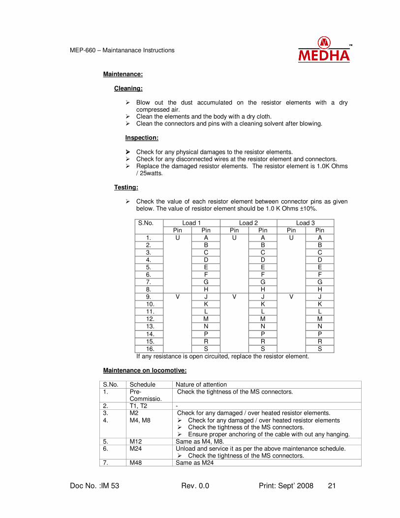
Maintenance:
Cleaning:
Blow out the dust accumulated on the resistor elements with a dry
compressed air. Clean the elements and the body with a dry cloth. Clean the connectors and pins with a cleaning solvent after blowing. Inspection: Check for any physical damages to the resistor elements. Check for any disconnected wires at the resistor element and connectors. Replace the damaged resistor elements. The resistor element is 1.0K Ohms
/ 25watts. Testing:
Check the value of each resistor element between connector pins as given below. The value of resistor element should be 1.0 K Ohms ±10%.
Load 1 Load 2 Load 3 S.No.
Pin Pin Pin Pin Pin Pin 1. A A A 2. B B B 3. C C C 4. D D D 5. E E E 6. F F F 7. G G G 8.
U
H
U
H
U
H 9. J J J 10. K K K 11. L L L 12. M M M 13. N N N
14. P P P 15. R R R 16.
V
S
V
S
V
S If any resistance is open circuited, replace the resistor element.
Maintenance on locomotive: S.No. Schedule Nature of attention 1. Pre-
Commissio. Check the tightness of the MS connectors.
2. T1, T2 - 3. M2 Check for any damaged / over heated resistor elements. 4. M4, M8 Check for any damaged / over heated resistor elements
Check the tightness of the MS connectors. Ensure proper anchoring of the cable with out any hanging.
5. M12 Same as M4, M8. 6. M24 Unload and service it as per the above maintenance schedule.
Check the tightness of the MS connectors. 7. M48 Same as M24
Doc No. :IM 53 Rev. 0.0 Print: Sept’ 2008 22
MEP-660 – Maintananace Instructions
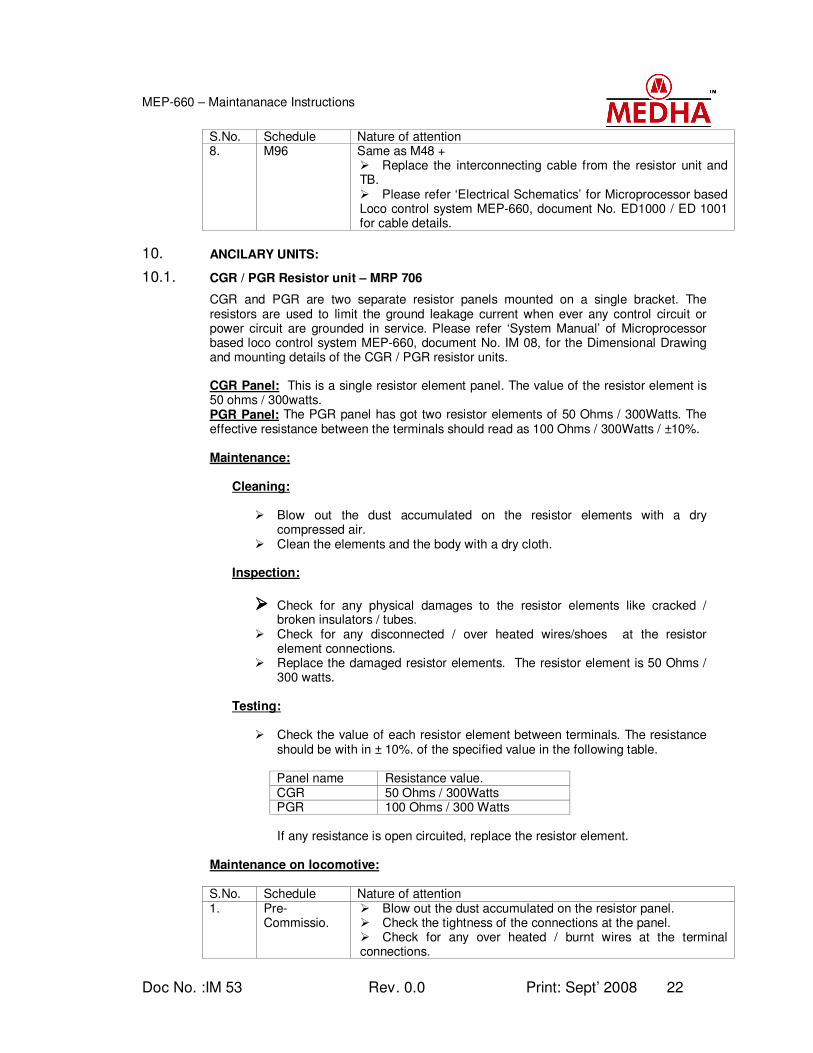
S.No. Schedule Nature of attention 8. M96 Same as M48 +
Replace the interconnecting cable from the resistor unit and TB. Please refer ‘Electrical Schematics’ for Microprocessor based Loco control system MEP-660, document No. ED1000 / ED 1001 for cable details.
10. ANCILARY UNITS:
10.1. CGR / PGR Resistor unit – MRP 706
CGR and PGR are two separate resistor panels mounted on a single bracket. The resistors are used to limit the ground leakage current when ever any control circuit or power circuit are grounded in service. Please refer ‘System Manual’ of Microprocessor based loco control system MEP-660, document No. IM 08, for the Dimensional Drawing and mounting details of the CGR / PGR resistor units. CGR Panel: This is a single resistor element panel. The value of the resistor element is 50 ohms / 300watts. PGR Panel: The PGR panel has got two resistor elements of 50 Ohms / 300Watts. The effective resistance between the terminals should read as 100 Ohms / 300Watts / ±10%. Maintenance:
Cleaning:
Blow out the dust accumulated on the resistor elements with a dry
compressed air. Clean the elements and the body with a dry cloth.
Inspection:
Check for any physical damages to the resistor elements like cracked / broken insulators / tubes.
Check for any disconnected / over heated wires/shoes at the resistor element connections.
Replace the damaged resistor elements. The resistor element is 50 Ohms / 300 watts.
Testing:
Check the value of each resistor element between terminals. The resistance should be with in ± 10%. of the specified value in the following table.
Panel name Resistance value. CGR 50 Ohms / 300Watts PGR 100 Ohms / 300 Watts If any resistance is open circuited, replace the resistor element.
Maintenance on locomotive: S.No. Schedule Nature of attention 1. Pre-
Commissio. Blow out the dust accumulated on the resistor panel. Check the tightness of the connections at the panel. Check for any over heated / burnt wires at the terminal connections.
Doc No. :IM 53 Rev. 0.0 Print: Sept’ 2008 23
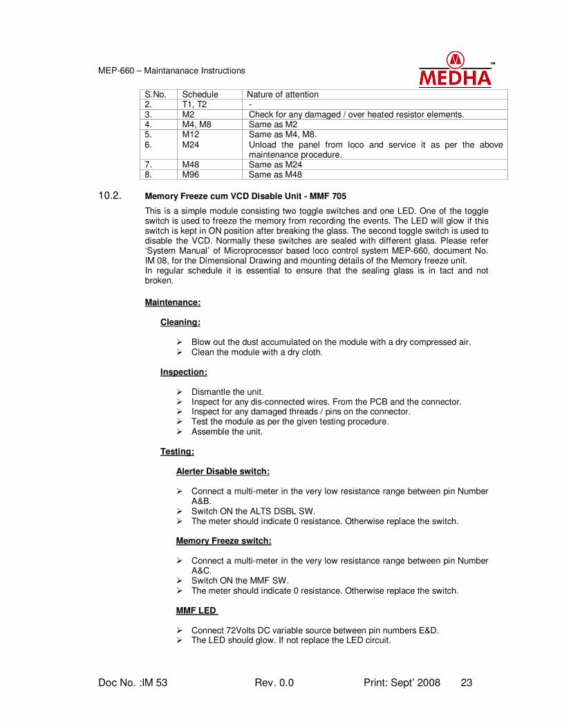
MEP-660 – Maintananace Instructions
S.No. Schedule Nature of attention 2. T1, T2 - 3. M2 Check for any damaged / over heated resistor elements. 4. M4, M8 Same as M2 5. M12 Same as M4, M8. 6. M24 Unload the panel from loco and service it as per the above
maintenance procedure. 7. M48 Same as M24 8. M96 Same as M48
10.2. Memory Freeze cum VCD Disable Unit - MMF 705
This is a simple module consisting two toggle switches and one LED. One of the toggle switch is used to freeze the memory from recording the events. The LED will glow if this switch is kept in ON position after breaking the glass. The second toggle switch is used to disable the VCD. Normally these switches are sealed with different glass. Please refer ‘System Manual’ of Microprocessor based loco control system MEP-660, document No. IM 08, for the Dimensional Drawing and mounting details of the Memory freeze unit. In regular schedule it is essential to ensure that the sealing glass is in tact and not broken.
Maintenance:
Cleaning:
Blow out the dust accumulated on the module with a dry compressed air. Clean the module with a dry cloth.
Inspection:
Dismantle the unit. Inspect for any dis-connected wires. From the PCB and the connector. Inspect for any damaged threads / pins on the connector. Test the module as per the given testing procedure. Assemble the unit.
Testing:
Alerter Disable switch:
Connect a multi-meter in the very low resistance range between pin Number A&B.
Switch ON the ALTS DSBL SW. The meter should indicate 0 resistance. Otherwise replace the switch.
Memory Freeze switch:
Connect a multi-meter in the very low resistance range between pin Number
A&C. Switch ON the MMF SW. The meter should indicate 0 resistance. Otherwise replace the switch. MMF LED
Connect 72Volts DC variable source between pin numbers E&D. The LED should glow. If not replace the LED circuit.
Doc No. :IM 53 Rev. 0.0 Print: Sept’ 2008 24
MEP-660 – Maintananace Instructions
Maintenance on locomotive: S.No. Schedule Nature of attention 1. Pre-
Commissio. Clean the module with dry cloth. Ensure sealing glass is in tact. If glass is broken replace the MMF box after providing the glass.
2. T1, T2 - 3. M2 Check the connector tightness of MMF cum VCD disable module. 4. M4, M8 Same as M2. 5. M12 Same as M4, M8. 6. M24 Remove the MMF box from the loco and service it as per the
above maintenance procedure. 7. M48 Same as M24 8. M96 Same as M48
10.3. XD23-XC13 Assembly unit
These are basically a protection components connected in the exciter field circuit to quench the inductive surges generated in the exciter field during switching operation of the PWM. Maintenance:
Cleaning:
Blow out the dust accumulated on the module with a dry compressed air. Clean the module with a dry cloth.
Inspection:
Base: Inspect the base for any cracks / broken pieces. The base should not have any cracks.
Heat sink: Check the heat sink for any flash over / burning marks. The heat sink should be clean and there should not be any flash over / burning marks.
Terminals and leads: Inspect the terminals and the leads for loose connections. There should not be any burning / over heated symptoms.
Tightness of the connections: The terminal stud should be tight on the base. The Diode connections should be tight on the terminal studs.
Shorting links: Shorting link plates should be available between diode connecting terminals and loco connection studs.
Check the capacitor connections are intact and the capacitor is in good condition.
Testing:
Diode: Measure forward resistance with a multi-meter. The forward resistance
should be between infinity (13.7MΩ) Measure the reverse resistance with a multi-meter. The reverse resistance
should be between low (10.3KΩ) If the Resistance values are deviated, replace the diode of same capacity.
Capacitor
Measure the capacitor value with an LCR meter. The value of the capacitor is 1µ fd.

Doc No. :IM 53 Rev. 0.0 Print: Sept’ 2008 25
MEP-660 – Maintananace Instructions
Maintenance on locomotive: S.No. Schedule Nature of attention 1. Pre-
Commissio. Clean the dust accumulated on the module with a dry cloth Check for any over heated / flash over marks on the terminals. If any overheating symptoms are found attend and check for any loose connections.
2. T1, T2 - 3. M2 Check for any over heated / flash over marks on the terminals.
Check the tightness of connecting terminals on Panel. 4. M4, M8 Same as M2 5. M12 Same as M4, M8. 6. M24 Remove the unit from loco and service it as per the above
maintenance schedule. While reconnecting ensure the connections are given correctly as per drawing. Please refer ‘Electrical Schematics’ for Microprocessor based Loco control system MEP-660, document No. ED1000 / ED 1001 for cable details.
7. M48 Same as M24 8. M96 Same as M48
10.4. Motor Cut Out Switch Box - MSP 707
This module is a traction motor isolation box used to isolate any defective traction motor in service. Six toggle switches are provided on the box with an ear marking of MCOS1 to MCOS6. Operating this switch on the locomotive will isolate the concerned traction motor. Maintenance:
Cleaning:
Blow out the dust accumulated on the module with a dry compressed air. Clean the module with a dry cloth.
Inspection:
Base: Inspect the box for any physical damages. Toggle switches: Check the physical condition of the switches. There should
not be any broken / damaged switches. Terminals and leads: Inspect the switch terminals and the leads for loose
connections. All the connections should be tight. If the connections are soldered inspect for any dry solder. There should not be any burning / over heated symptoms.
Connector connections: The wires coming from the switches should have good soldering at the connector. Inspect for the interconnecting leads. Replace any damaged leads.
Connector: Check for any damaged pins or damaged threads on the connector.
Testing:
Measure contact resistance of each toggle switch between the pins of the connector as below. There should not be any resistance.
Doc No. :IM 53 Rev. 0.0 Print: Sept’ 2008 26
MEP-660 – Maintananace Instructions
Between pins of the connector Resistance between pins
A
B
C
D
E
G
F
Maintenance on locomotive: S.No. Schedule Nature of attention 1. Pre-
Commissio. Clean the dust accumulated on the module with a dry cloth Ensure the switches are in normal position. Check the tightness of MS connector.
2. T1, T2 - 3. M2 Ensure the switches are in normal position.
Check the tightness of MS connector. 4. M4, M8 Same as M2 5. M12 Same as M4, M8. 6. M24 Remove the unit from loco and service it as per the above
maintenance schedule.
While reconnecting ensure the connections are given correctly as per drawing.
Please refer ‘Electrical Schematics’ for Microprocessor based Loco control system MEP-660, document No. ED1000 / ED 1001 for cable details.
7. M48 Same as M24 8. M96 Same as M48
10.5. Speed Sensor Interface Unit - MSI 761
This module is an interface unit to split the engine speed signal into two isolated speed signals. One set of speed signals derived from ESS1 / ESS2 are connected to MEP-660. The second set of speed signals are connected to MCBG. In this unit one toggle switch is provided to select MEG601 or Other governor mode. The switch should be always on ‘MEG601’ side if Medha make MCBG is connected other wise the switch should be kept in ‘Others’ position. Maintenance:
Cleaning:
Blow out the dust accumulated on the module with a dry compressed air. Clean the module with a dry cloth. Inspection: Base: Inspect the box for any physical damages. Toggle switch: Check the physical condition of the switch. There should not
be any broken / damaged switch. Terminals and leads: Inspect the switch terminals and the wiring for any dry
solder / disconnected wires. All the connections should be tight. There should not be any burning / over heated symptoms.
Doc No. :IM 53 Rev. 0.0 Print: Sept’ 2008 27
MEP-660 – Maintananace Instructions
Connectors: Check for any damaged pins or damaged threads on the connectors. Check the soldering condition of the wires for any dry solder / broken strands of the wire. If any damages are found, re-solder the wires.
Maintenance on locomotive: S.No. Schedule Nature of attention 1. Pre-
Commissio. Clean the dust accumulated on the module with a dry cloth. Check the tightness of connectors.
2. T1, T2 - 3. M2 Check the tightness of connectors. 4. M4, M8 Same as M2 5. M12 Same as M4, M8. 6. M24 Remove the unit from loco and service it as per the above
maintenance schedule.
While reconnecting ensure the connections are given correctly as per drawing.
Please refer ‘Electrical Schematics’ for Microprocessor based Loco control system MEP-660, document No. ED1000 / ED 1001 for cable details.
7. M48 Same as M24 8. M96 Same as M48
10.6. FCP Panel – Type SFCP - 25
Field Control Panel (FCP) is a resistor panel. These resistors are used in the Exciter field circuit to drop the voltage from 72V to the required level. This panel consists of four adjustable resistors. Maintenance:
Cleaning:
Blow out the dust accumulated on the resistor elements with a dry
compressed air. Clean the elements and the body with a dry cloth. Clean the terminals from dust. Inspection: Check for any physical damages to the resistor elements. Replace the
damaged resistor elements if any with same value. Check for any over heated lugs at the resistor elements. If found replace the
lugs. Check for any disconnected wires at the resistor element and connectors. Check the tightness of adjustable clamps on the resistor element.
Testing:
Check the values of each resistor between the terminals specified in brackets. The values of each resistor are as under. If the resistance values are deviated, adjust the values with in the range. If any resistance is open circuited, replace the resistor element.
EFR1 ---69.5 to 70.5 ohms (B-C) EFR2 ---1.38 to 1.42 ohms (C-D) EFR3 ---14.5 to 14.7 ohms (E-F) EFR4 ---2.65 to 2.75 ohms (D-E)
Doc No. :IM 53 Rev. 0.0 Print: Sept’ 2008 28
MEP-660 – Maintananace Instructions
Maintenance on locomotive: S.No. Schedule Nature of attention 1. Pre-
Commissio. Check for any damaged / over heated resistor elements. Check for any over heated lugs on the terminals or at resistor elements. If so replace the FCP.
2. T1, T2 - 3. M2 Check for any damaged / over heated resistor elements
Ensure proper anchoring of the connecting wires with out any loose hanging.
4. M4, M8 Same as M2 5. M12 Same as M4, M8. 6. M24 Unload and service it as per the above maintenance schedule. 7. M48 Same as M24. 8. M96 Same as M48 +
Replace the interconnecting wires between the resistor element and TB.
Harness the wires properly.
10.7. HLD Relay Module - MRA 710
This is a simple relay module incorporated in the head light circuit. With introduction of DC-DC converter instead of HLPR for headlight, the output voltage signal is 24 volts. Any digital input signals are recognized as high when the voltage is more than 30V. So simple relay logic has been used to convert this 24VDC signal into 72VDC signal. The status of the headlight is sensed through this relay box and is communicated to MEP-660 and recorded in the event recorder.
Maintenance:
Cleaning:
Blow out the dust accumulated on the module with a dry compressed air. Clean the module with a dry cloth.
Inspection:
Dismantle the unit. Inspect for any disconnected wires. Check the tightness of connecting wires on TB Test the module as per the given testing procedure. Assemble the unit.
Testing:
Connect 72 Volts DC power supply to the HLD relay module across 50A & 52HL terminals.
Check the voltage across HLB - 52HL and HLD-52HL. The voltage should be zero. If voltage is available at HLB and HLD terminals, replace the 24V relays on the PCB.
Apply 24 volts between HLBR and 52HL. Measure the voltage between HLB and 52H terminals. The Voltage should
be same as applied across 50A and 52HL. If voltage is zero or less than the 72V, replace the 24V relay on the PCB. Remove 24 volts and connect between HLDR and 52HL. Measure the voltage across HLD and 52HL. The voltage should be same as
applied across 50A and 52HL.
Doc No. :IM 53 Rev. 0.0 Print: Sept’ 2008 29
MEP-660 – Maintananace Instructions
If voltage is zero or less than the 72V, replace the 24V relay on the PCB. Disconnect all the supply wires.
Maintenance on locomotive: S.No. Schedule Nature of attention 1. Pre-
Commissio. Clean the dust accumulated on the module with a dry cloth
2. T1, T2 - 3. M2 Check the tightness of connecting terminals. 4. M4, M8 Same as M2. 5. M12 Same as M4, M8. 6. M24 Remove the HLD Relay module from the loco and service it as
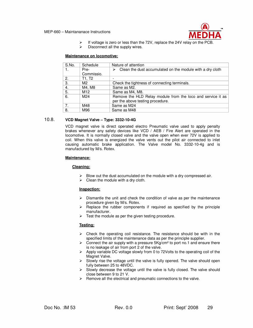
per the above testing procedure. 7. M48 Same as M24 8. M96 Same as M48
10.8. VCD Magnet Valve – Type: 3332-10-4G
VCD magnet valve is direct operated electro Pneumatic valve used to apply penalty brakes whenever any safety devices like VCD / AEB / Fire Alert are operated in the locomotive. It is normally closed valve and the valve open when ever 72V is applied to coil. When this valve is energized the valve vents out the pilot air connected to inlet causing automatic brake application. The Valve model No. 3332-10-4g and is manufactured by M/s. Rotex.
Maintenance:
Cleaning:
Blow out the dust accumulated on the module with a dry compressed air. Clean the module with a dry cloth.
Inspection: Dismantle the unit and check the condition of valve as per the maintenance
procedure given by M/s. Rotex. Replace the rubber components if required as specified by the principle
manufacturer. Test the module as per the given testing procedure.
Testing: Check the operating coil resistance. The resistance should be with in the
specified limits of the maintenance data as per the principle supplier. Connect the air supply with a pressure 5Kg/cm² to port no.1 and ensure there
is no leakage of air from port 2 of the valve. Apply variable DC voltage slowly from 0 to 72Volts to the operating coil of the
Magnet Valve. Slowly rise the voltage until the valve is fully opened. The valve should open
fully between 25 to 48VDC. Slowly decrease the voltage until the valve is fully closed. The valve should
close between 9 to 21 V. Remove all the electrical and pneumatic connections to the valve.
Doc No. :IM 53 Rev. 0.0 Print: Sept’ 2008 30
MEP-660 – Maintananace Instructions
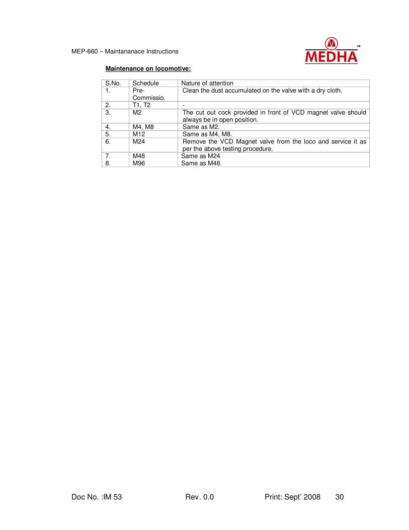
Maintenance on locomotive: S.No. Schedule Nature of attention 1. Pre-
Commissio. Clean the dust accumulated on the valve with a dry cloth.
2. T1, T2 - 3. M2 The cut out cock provided in front of VCD magnet valve should
always be in open position. 4. M4, M8 Same as M2. 5. M12 Same as M4, M8. 6. M24 Remove the VCD Magnet valve from the loco and service it as
per the above testing procedure. 7. M48 Same as M24 8. M96 Same as M48.
Doc No. :IM 53 Rev. 0.0 Print: Sept’ 2008 31
MEP-660 – Maintananace Instructions
Annexure 1
Doc No. :IM 53 Rev. 0.0 Print: Sept’ 2008 32
MEP-660 – Maintananace Instructions
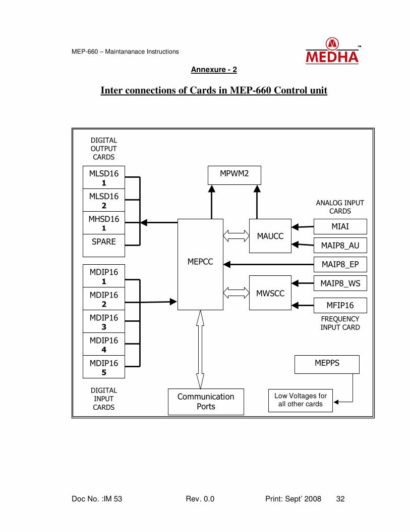
Annexure - 2
Inter connections of Cards in MEP-660 Control unit
MDIP16 1
MDIP16 2
MDIP16 3
MDIP16 4
MDIP16 5
DIGITAL
INPUT
CARDS
MLSD16 2
MHSD16 1
SPARE
MLSD16 1
DIGITAL
OUTPUT
CARDS
MAIP8_AU
MIAI
MAIP8_EP
MAIP8_WS
ANALOG INPUT
CARDS
MPWM2
MEPCC
MAUCC
MWSCC
Communication
Ports
FREQUENCY
INPUT CARD
MFIP16
MEPPS
Low Voltages for all other cards
Doc No. :IM 53 Rev. 0.0 Print: Sept’ 2008 33
MEP-660 – Maintananace Instructions
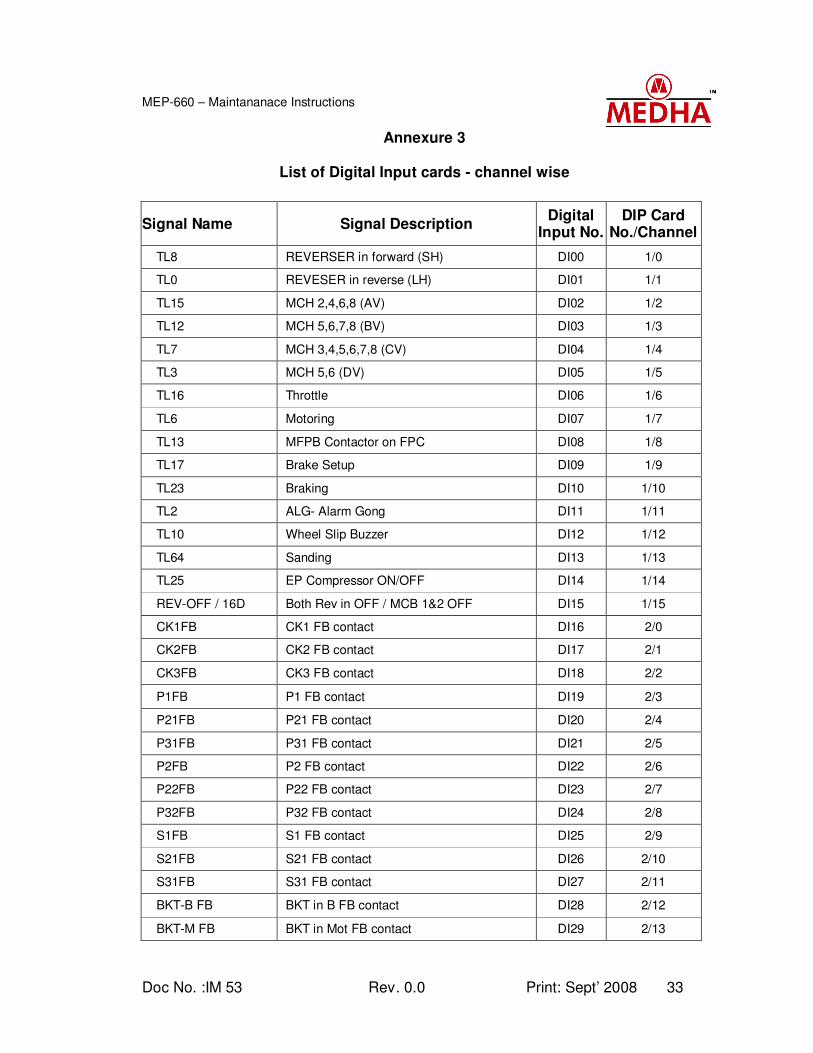
Annexure 3
List of Digital Input cards - channel wise
Signal Name Signal Description Digital
Input No. DIP Card
No./Channel
TL8 REVERSER in forward (SH) DI00 1/0
TL0 REVESER in reverse (LH) DI01 1/1
TL15 MCH 2,4,6,8 (AV) DI02 1/2
TL12 MCH 5,6,7,8 (BV) DI03 1/3
TL7 MCH 3,4,5,6,7,8 (CV) DI04 1/4
TL3 MCH 5,6 (DV) DI05 1/5
TL16 Throttle DI06 1/6
TL6 Motoring DI07 1/7
TL13 MFPB Contactor on FPC DI08 1/8
TL17 Brake Setup DI09 1/9
TL23 Braking DI10 1/10
TL2 ALG- Alarm Gong DI11 1/11
TL10 Wheel Slip Buzzer DI12 1/12
TL64 Sanding DI13 1/13
TL25 EP Compressor ON/OFF DI14 1/14
REV-OFF / 16D Both Rev in OFF / MCB 1&2 OFF DI15 1/15
CK1FB CK1 FB contact DI16 2/0
CK2FB CK2 FB contact DI17 2/1
CK3FB CK3 FB contact DI18 2/2
P1FB P1 FB contact DI19 2/3
P21FB P21 FB contact DI20 2/4
P31FB P31 FB contact DI21 2/5
P2FB P2 FB contact DI22 2/6
P22FB P22 FB contact DI23 2/7
P32FB P32 FB contact DI24 2/8
S1FB S1 FB contact DI25 2/9
S21FB S21 FB contact DI26 2/10
S31FB S31 FB contact DI27 2/11
BKT-B FB BKT in B FB contact DI28 2/12
BKT-M FB BKT in Mot FB contact DI29 2/13
Doc No. :IM 53 Rev. 0.0 Print: Sept’ 2008 34
MEP-660 – Maintananace Instructions
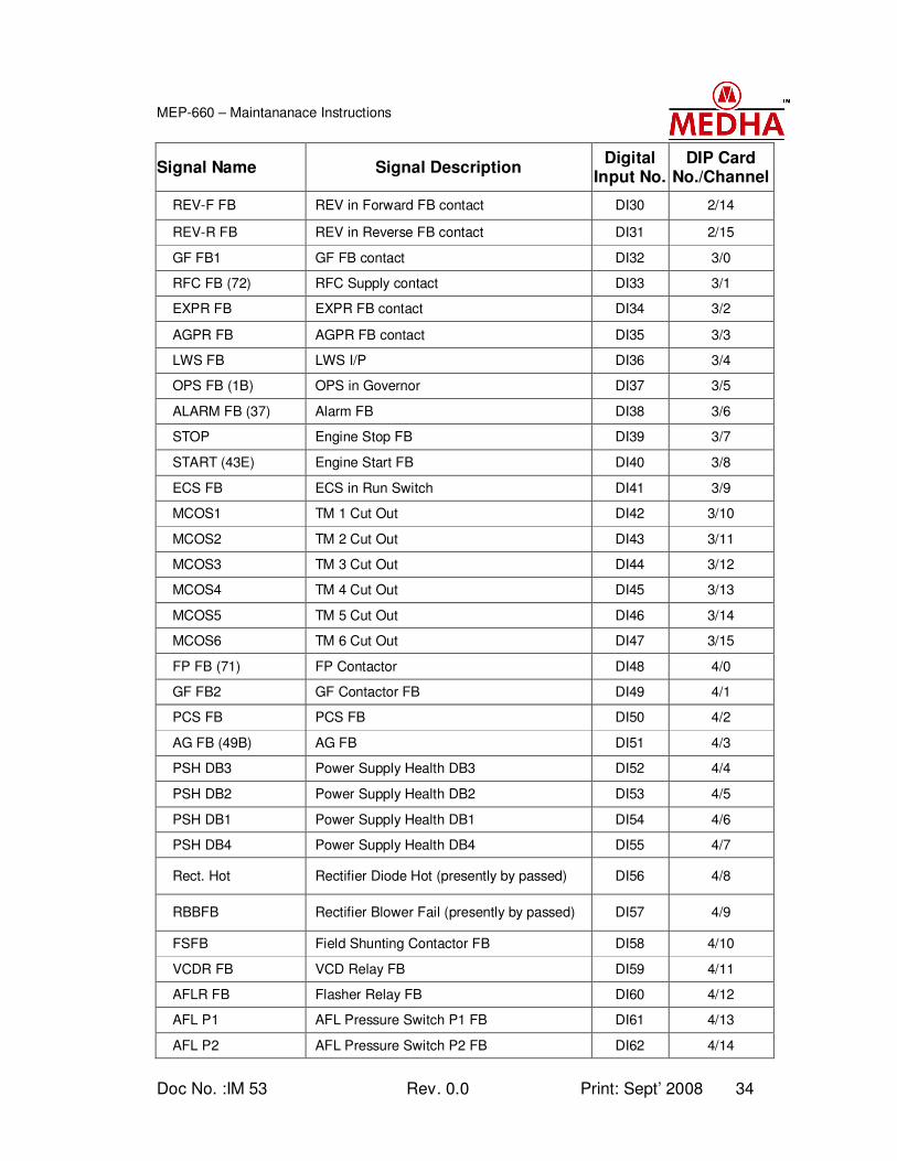
Signal Name Signal Description Digital
Input No. DIP Card
No./Channel
REV-F FB REV in Forward FB contact DI30 2/14
REV-R FB REV in Reverse FB contact DI31 2/15
GF FB1 GF FB contact DI32 3/0
RFC FB (72) RFC Supply contact DI33 3/1
EXPR FB EXPR FB contact DI34 3/2
AGPR FB AGPR FB contact DI35 3/3
LWS FB LWS I/P DI36 3/4
OPS FB (1B) OPS in Governor DI37 3/5
ALARM FB (37) Alarm FB DI38 3/6
STOP Engine Stop FB DI39 3/7
START (43E) Engine Start FB DI40 3/8
ECS FB ECS in Run Switch DI41 3/9
MCOS1 TM 1 Cut Out DI42 3/10
MCOS2 TM 2 Cut Out DI43 3/11
MCOS3 TM 3 Cut Out DI44 3/12
MCOS4 TM 4 Cut Out DI45 3/13
MCOS5 TM 5 Cut Out DI46 3/14
MCOS6 TM 6 Cut Out DI47 3/15
FP FB (71) FP Contactor DI48 4/0
GF FB2 GF Contactor FB DI49 4/1
PCS FB PCS FB DI50 4/2
AG FB (49B) AG FB DI51 4/3
PSH DB3 Power Supply Health DB3 DI52 4/4
PSH DB2 Power Supply Health DB2 DI53 4/5
PSH DB1 Power Supply Health DB1 DI54 4/6
PSH DB4 Power Supply Health DB4 DI55 4/7
Rect. Hot Rectifier Diode Hot (presently by passed) DI56 4/8
RBBFB Rectifier Blower Fail (presently by passed) DI57 4/9
FSFB Field Shunting Contactor FB DI58 4/10
VCDR FB VCD Relay FB DI59 4/11
AFLR FB Flasher Relay FB DI60 4/12
AFL P1 AFL Pressure Switch P1 FB DI61 4/13
AFL P2 AFL Pressure Switch P2 FB DI62 4/14
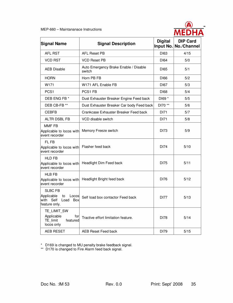
Doc No. :IM 53 Rev. 0.0 Print: Sept’ 2008 35
MEP-660 – Maintananace Instructions
Signal Name Signal Description Digital
Input No. DIP Card
No./Channel
AFL RST AFL Reset PB DI63 4/15
VCD RST VCD Reset PB DI64 5/0
AEB Disable Auto Emergency Brake Enable / Disable switch
DI65 5/1
HORN Horn PB FB DI66 5/2
W171 W171 AFL Enable FB DI67 5/3
PCS1 PCS1 FB DI68 5/4
DEB ENG FB * Dust Exhauster Breaker Engine Feed back DI69 * 5/5
DEB CB-FB ** Dust Exhauster Breaker Car body Feed back DI70 ** 5/6
CEBFB Crankcase Exhauster Breaker Feed back DI71 5/7
ALTR DSBL FB VCD disable switch DI71 5/8
MMF FB
Applicable to locos with event recorder
Memory Freeze switch DI73 5/9
FL FB
Applicable to locos with event recorder
Flasher feed back DI74 5/10
HLD FB
Applicable to locos with event recorder
Headlight Dim Feed back DI75 5/11
HLB FB
Applicable to locos with event recorder
Headlight Bright feed back DI76 5/12
SLBC FB
Applicable to Locos with Self Load Box feature only.
Self load box contactor Feed back DI77 5/13
TE_LIMIT_SW
Applicable for TE_limit featured locos only
Tractive effort limitation feature. DI78 5/14
AEB RESET AEB Reset Feed back DI79 5/15
* D169 is changed to MU penalty brake feedback signal. ** D170 is changed to Fire Alarm feed back signal.
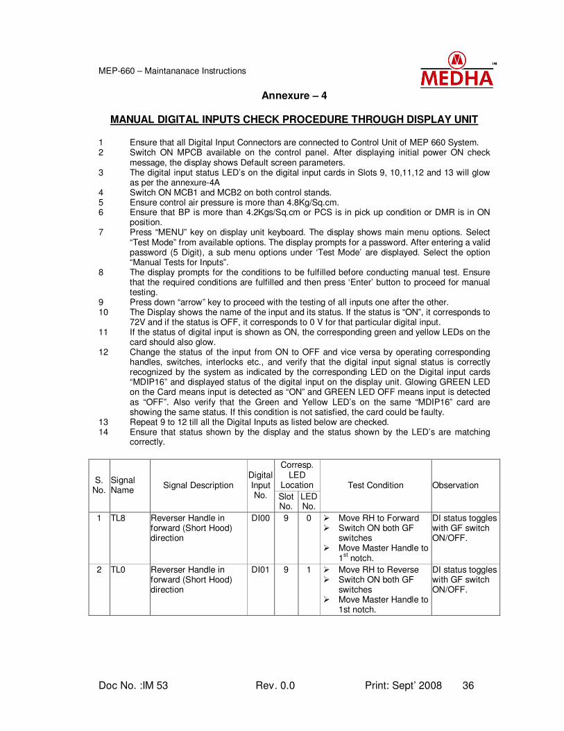
Doc No. :IM 53 Rev. 0.0 Print: Sept’ 2008 36
MEP-660 – Maintananace Instructions
Annexure – 4
MANUAL DIGITAL INPUTS CHECK PROCEDURE THROUGH DISPLAY UNIT 1 Ensure that all Digital Input Connectors are connected to Control Unit of MEP 660 System. 2 Switch ON MPCB available on the control panel. After displaying initial power ON check
message, the display shows Default screen parameters. 3 The digital input status LED’s on the digital input cards in Slots 9, 10,11,12 and 13 will glow
as per the annexure-4A 4 Switch ON MCB1 and MCB2 on both control stands. 5 Ensure control air pressure is more than 4.8Kg/Sq.cm. 6 Ensure that BP is more than 4.2Kgs/Sq.cm or PCS is in pick up condition or DMR is in ON
position. 7 Press “MENU” key on display unit keyboard. The display shows main menu options. Select
“Test Mode” from available options. The display prompts for a password. After entering a valid password (5 Digit), a sub menu options under ‘Test Mode’ are displayed. Select the option “Manual Tests for Inputs”.
8 The display prompts for the conditions to be fulfilled before conducting manual test. Ensure that the required conditions are fulfilled and then press ‘Enter’ button to proceed for manual testing.
9 Press down “arrow” key to proceed with the testing of all inputs one after the other. 10 The Display shows the name of the input and its status. If the status is “ON”, it corresponds to
72V and if the status is OFF, it corresponds to 0 V for that particular digital input. 11 If the status of digital input is shown as ON, the corresponding green and yellow LEDs on the
card should also glow. 12 Change the status of the input from ON to OFF and vice versa by operating corresponding
handles, switches, interlocks etc., and verify that the digital input signal status is correctly recognized by the system as indicated by the corresponding LED on the Digital input cards “MDIP16” and displayed status of the digital input on the display unit. Glowing GREEN LED on the Card means input is detected as “ON” and GREEN LED OFF means input is detected as “OFF”. Also verify that the Green and Yellow LED’s on the same “MDIP16” card are showing the same status. If this condition is not satisfied, the card could be faulty.
13 Repeat 9 to 12 till all the Digital Inputs as listed below are checked. 14 Ensure that status shown by the display and the status shown by the LED’s are matching
correctly.
Corresp.
LED Location
S. No.
Signal Name
Signal Description Digital Input No. Slot
No. LED No.
Test Condition Observation
1 TL8 Reverser Handle in forward (Short Hood) direction
DI00 9 0 Move RH to Forward Switch ON both GF
switches Move Master Handle to
1st notch.
DI status toggles with GF switch ON/OFF.
2 TL0 Reverser Handle in forward (Short Hood) direction
DI01 9 1 Move RH to Reverse Switch ON both GF
switches Move Master Handle to
1st notch.
DI status toggles with GF switch ON/OFF.
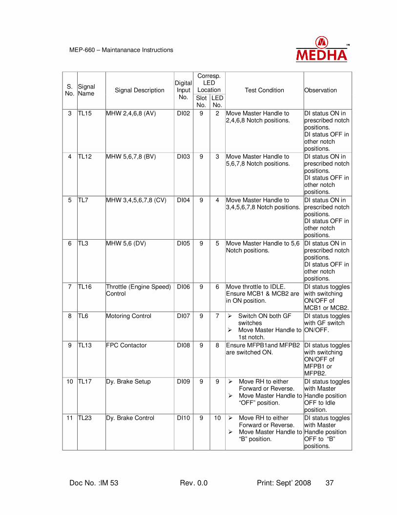
Doc No. :IM 53 Rev. 0.0 Print: Sept’ 2008 37
MEP-660 – Maintananace Instructions
Corresp.
LED Location
S. No.
Signal Name
Signal Description Digital Input No. Slot
No. LED No.
Test Condition Observation
3 TL15 MHW 2,4,6,8 (AV) DI02 9 2 Move Master Handle to 2,4,6,8 Notch positions.
DI status ON in prescribed notch positions. DI status OFF in other notch positions.
4 TL12 MHW 5,6,7,8 (BV) DI03 9 3 Move Master Handle to 5,6,7,8 Notch positions.
DI status ON in prescribed notch positions. DI status OFF in other notch positions.
5 TL7 MHW 3,4,5,6,7,8 (CV) DI04 9 4 Move Master Handle to 3,4,5,6,7,8 Notch positions.
DI status ON in prescribed notch positions. DI status OFF in other notch positions.
6 TL3 MHW 5,6 (DV) DI05 9 5 Move Master Handle to 5,6 Notch positions.
DI status ON in prescribed notch positions. DI status OFF in other notch positions.
7 TL16 Throttle (Engine Speed) Control
DI06 9 6 Move throttle to IDLE. Ensure MCB1 & MCB2 are in ON position.
DI status toggles with switching ON/OFF of MCB1 or MCB2.
8 TL6 Motoring Control DI07 9 7 Switch ON both GF switches
Move Master Handle to 1st notch.
DI status toggles with GF switch ON/OFF.
9 TL13 FPC Contactor DI08 9 8 Ensure MFPB1and MFPB2 are switched ON.
DI status toggles with switching ON/OFF of MFPB1 or MFPB2.
10 TL17 Dy. Brake Setup DI09 9 9 Move RH to either Forward or Reverse.
Move Master Handle to “OFF” position.
DI status toggles with Master Handle position OFF to Idle position.
11 TL23 Dy. Brake Control DI10 9 10 Move RH to either Forward or Reverse.
Move Master Handle to “B” position.
DI status toggles with Master Handle position OFF to “B” positions.
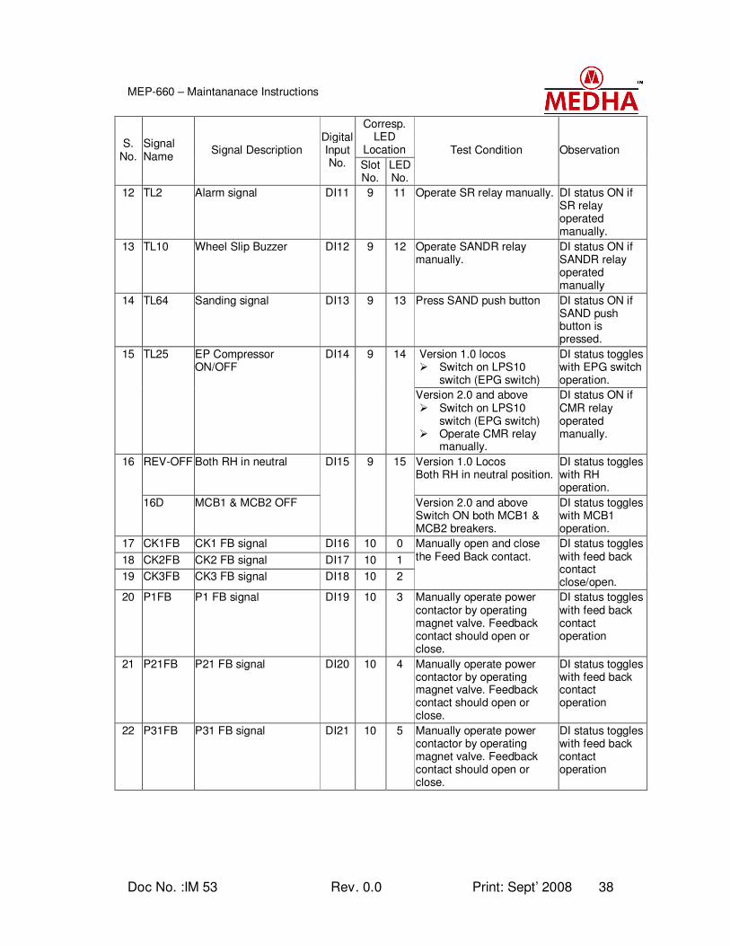
Doc No. :IM 53 Rev. 0.0 Print: Sept’ 2008 38
MEP-660 – Maintananace Instructions
Corresp. LED
Location S.
No. Signal Name
Signal Description Digital Input No. Slot
No. LED No.
Test Condition Observation
12 TL2 Alarm signal DI11 9 11 Operate SR relay manually. DI status ON if SR relay operated manually.
13 TL10 Wheel Slip Buzzer DI12 9 12 Operate SANDR relay manually.
DI status ON if SANDR relay operated manually
14 TL64 Sanding signal DI13 9 13 Press SAND push button DI status ON if SAND push button is pressed.
Version 1.0 locos Switch on LPS10
switch (EPG switch)
DI status toggles with EPG switch operation.
15 TL25 EP Compressor ON/OFF
DI14 9 14
Version 2.0 and above Switch on LPS10
switch (EPG switch) Operate CMR relay
manually.
DI status ON if CMR relay operated manually.
REV-OFF Both RH in neutral Version 1.0 Locos Both RH in neutral position.
DI status toggles with RH operation.
16
16D MCB1 & MCB2 OFF
DI15 9 15
Version 2.0 and above Switch ON both MCB1 & MCB2 breakers.
DI status toggles with MCB1 operation.
17 CK1FB CK1 FB signal DI16 10 0
18 CK2FB CK2 FB signal DI17 10 1
19 CK3FB CK3 FB signal DI18 10 2
Manually open and close the Feed Back contact.
DI status toggles with feed back contact close/open.
20 P1FB P1 FB signal DI19 10 3 Manually operate power contactor by operating magnet valve. Feedback contact should open or close.
DI status toggles with feed back contact operation
21 P21FB P21 FB signal DI20 10 4 Manually operate power contactor by operating magnet valve. Feedback contact should open or close.
DI status toggles with feed back contact operation
22 P31FB P31 FB signal DI21 10 5 Manually operate power contactor by operating magnet valve. Feedback contact should open or close.
DI status toggles with feed back contact operation
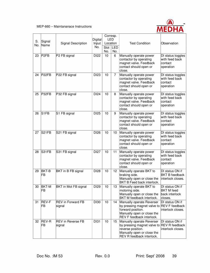
Doc No. :IM 53 Rev. 0.0 Print: Sept’ 2008 39
MEP-660 – Maintananace Instructions
Corresp. LED
Location S.
No. Signal Name
Signal Description Digital Input No. Slot
No. LED No.
Test Condition Observation
23 P2FB P2 FB signal DI22 10 6 Manually operate power contactor by operating magnet valve. Feedback contact should open or close.
DI status toggles with feed back contact operation
24 P22FB P22 FB signal DI23 10 7 Manually operate power contactor by operating magnet valve. Feedback contact should open or close.
DI status toggles with feed back contact operation
25 P32FB P32 FB signal DI24 10 8 Manually operate power contactor by operating magnet valve. Feedback contact should open or close.
DI status toggles with feed back contact operation
26 S1FB S1 FB signal DI25 10 9 Manually operate power contactor by operating magnet valve. Feedback contact should open or close.
DI status toggles with feed back contact operation
27 S21FB S21 FB signal DI26 10 10 Manually operate power contactor by operating magnet valve. Feedback contact should open or close.
DI status toggles with feed back contact operation
28 S31FB S31 FB signal DI27 10 11 Manually operate power contactor by operating magnet valve. Feedback contact should open or close.
DI status toggles with feed back contact operation
29 BKT-B FB
BKT in B FB signal DI28 10 12 Manually operate BKT to braking side. Manually open or close the BKT B Feed back interlock.
DI status ON if BKT B feedback interlock closes.
30 BKT-M FB
BKT in Mot FB signal DI29 10 13 Manually operate BKT to motoring side. Manually open or close the BKT M feedback interlock.
DI status ON if BKT M feed back interlock closes.
31 REV-F FB
REV in Forward FB signal
DI30 10 14 Manually operate Reverser by pressing magnet valve to forward position. Manually open or close the REV F feedback interlock.
DI status ON if REV F feedback interlock closes.
32 REV-R FB
REV in Reverse FB signal
DI31 10 15 Manually operate Reverser by pressing magnet valve to reverse position. Manually open or close the REV R feedback interlock.
DI status ON if REV R feedback interlock closes.
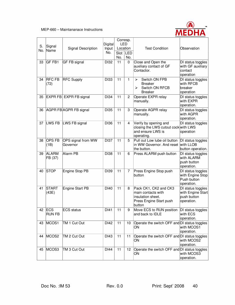
Doc No. :IM 53 Rev. 0.0 Print: Sept’ 2008 40
MEP-660 – Maintananace Instructions
Corresp. LED
Location S.
No. Signal Name
Signal Description Digital Input No. Slot
No. LED No.
Test Condition Observation
33 GF FB1 GF FB signal DI32 11 0 Close and Open the auxiliary contact of GF Contactor.
DI status toggles with GF auxiliary contact operation
34 RFC FB (72)
RFC Supply DI33 11 1 Switch ON FPB Breaker
Switch ON RFCB Breaker
DI status toggles with RFCB breaker operation
35 EXPR FB EXPR FB signal DI34 11 2 Operate EXPR relay manually.
DI status toggles with EXPR operation.
36 AGPR FB AGPR FB signal DI35 11 3 Operate AGPR relay manually.
DI status toggles with AGPR operation.
37 LWS FB LWS FB signal DI36 11 4 Verify by opening and closing the LWS cutout cock and ensure LWS is operating.
DI status toggles with LWS operation
38 OPS FB (1B)
OPS signal from WW Governor
DI37 11 5 Pull out Low lube oil button in WW Governor. And reset the button.
DI status toggles with LLOB button operation.
39 ALARM FB (37)
Alarm PB DI38 11 6 Press ALARM push button DI status toggles with ALARM push button operation.
40 STOP Engine Stop PB DI39 11 7 Press Engine Stop push button
DI status toggles with Engine Stop Push button operation.
41 START (43E)
Engine Start PB DI40 11 8 Pack CK1, CK2 and CK3 main contacts with insulation sheet. Press Engine Start push button
DI status toggles with Engine Start push button operation.
42 ECS RUN FB
ECS status DI41 11 9 Move ECS to RUN position and back to IDLE
DI status toggles with ECS operation.
43 MCOS1 TM 1 Cut Out DI42 11 10 Operate the switch OFF and ON
DI status toggles with MCOS1 operation.
44 MCOS2 TM 2 Cut Out DI43 11 11 Operate the switch OFF and ON
DI status toggles with MCOS2 operation.
45 MCOS3 TM 3 Cut Out DI44 11 12 Operate the switch OFF and ON
DI status toggles with MCOS3 operation.
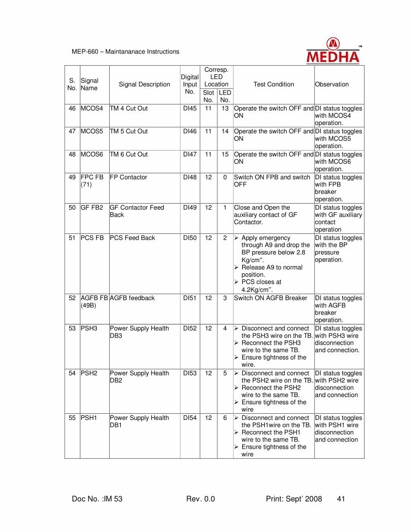
Doc No. :IM 53 Rev. 0.0 Print: Sept’ 2008 41
MEP-660 – Maintananace Instructions
Corresp. LED
Location S.
No. Signal Name
Signal Description Digital Input No. Slot
No. LED No.
Test Condition Observation
46 MCOS4 TM 4 Cut Out DI45 11 13 Operate the switch OFF and ON
DI status toggles with MCOS4 operation.
47 MCOS5 TM 5 Cut Out DI46 11 14 Operate the switch OFF and ON
DI status toggles with MCOS5 operation.
48 MCOS6 TM 6 Cut Out DI47 11 15 Operate the switch OFF and ON
DI status toggles with MCOS6 operation.
49 FPC FB (71)
FP Contactor DI48 12 0 Switch ON FPB and switch OFF
DI status toggles with FPB breaker operation.
50 GF FB2 GF Contactor Feed Back
DI49 12 1 Close and Open the auxiliary contact of GF Contactor.
DI status toggles with GF auxiliary contact operation
51 PCS FB PCS Feed Back DI50 12 2 Apply emergency through A9 and drop the BP pressure below 2.8
Kg/cm″. Release A9 to normal
position. PCS closes at
4.2Kg/cm″.
DI status toggles with the BP pressure operation.
52 AGFB FB (49B)
AGFB feedback DI51 12 3 Switch ON AGFB Breaker DI status toggles with AGFB breaker operation.
53 PSH3 Power Supply Health DB3
DI52 12 4 Disconnect and connect the PSH3 wire on the TB.
Reconnect the PSH3 wire to the same TB.
Ensure tightness of the wire.
DI status toggles with PSH3 wire disconnection and connection.
54 PSH2 Power Supply Health DB2
DI53 12 5 Disconnect and connect the PSH2 wire on the TB.
Reconnect the PSH2 wire to the same TB.
Ensure tightness of the wire
DI status toggles with PSH2 wire disconnection and connection
55 PSH1 Power Supply Health DB1
DI54 12 6 Disconnect and connect the PSH1wire on the TB.
Reconnect the PSH1 wire to the same TB.
Ensure tightness of the wire
DI status toggles with PSH1 wire disconnection and connection
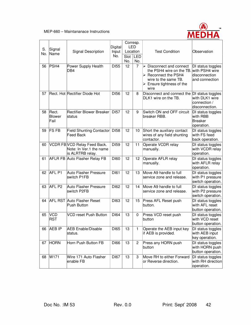
Doc No. :IM 53 Rev. 0.0 Print: Sept’ 2008 42
MEP-660 – Maintananace Instructions
Corresp. LED
Location S.
No. Signal Name
Signal Description Digital Input No. Slot
No. LED No.
Test Condition Observation
56 PSH4 Power Supply Health DB4
DI55 12 7 Disconnect and connect the PSH4 wire on the TB.
Reconnect the PSH4 wire to the same TB.
Ensure tightness of the wire
DI status toggles with PSH4 wire disconnection and connection
57 Rect. Hot Rectifier Diode Hot DI56 12 8 Disconnect and connect the DLK1 wire on the TB.
DI status toggles with DLK1 wire connection / disconnection.
58 Rect. Blower Fail
Rectifier Blower Breaker status
DI57 12 9 Switch ON and OFF circuit breaker RBB.
DI status toggles with RBB Breaker operation.
59 FS FB Field Shunting Contactor Feed Back
DI58 12 10 Short the auxiliary contact wires of any field shunting contactor.
DI status toggles with FS feed back operation.
60 VCDR FB VCD Relay Feed Back. Note: In Ver.1 the name is ALRTRB relay.
DI59 12 11 Operate VCDR relay manually.
DI status toggles with VCDR relay operation.
61 AFLR FB Auto Flasher Relay FB DI60 12 12 Operate AFLR relay manually.
DI status toggles with AFLR relay operation.
62 AFL P1 Auto Flasher Pressure switch P1FB
DI61 12 13 Move A9 handle to full service zone and release.
DI status toggles with P1 pressure switch operation.
63 AFL P2 Auto Flasher Pressure switch P2FB
DI62 12 14 Move A9 handle to full service zone and release.
DI status toggles with P2 pressure switch operation.
64 AFL RST Auto Flasher Reset Push Button
DI63 12 15 Press AFL Reset push button.
DI status toggles with AFL reset button operation.
65 VCD RST
VCD reset Push Button DI64 13 0 Press VCD reset push button
DI status toggles with VCD reset button operation.
66 AEB IP AEB Enable/Disable status.
DI65 13 1 Operate the AEB input key if AEB is provided.
DI status toggles with AEB input key operation.
67 HORN Horn Push Button FB DI66 13 2 Press any HORN push button
DI status toggles with HORN push button operation.
68 W171 Wire 171 Auto Flasher enable FB
DI67 13 3 Move RH to either Forward or Reverse direction.
DI status toggles with RH direction operation.
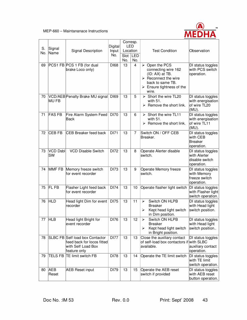
Doc No. :IM 53 Rev. 0.0 Print: Sept’ 2008 43
MEP-660 – Maintananace Instructions
Corresp. LED
Location S.
No. Signal Name
Signal Description Digital Input No. Slot
No. LED No.
Test Condition Observation
69 PCS1 FB PCS 1 FB (for dual brake Loco only)
DI68 13 4 Open the PCS connecting wire 162 (ID: AX) at TB.
Reconnect the wire back to same TB.
Ensure tightness of the wire.
DI status toggles with PCS switch operation.
70 VCD/AEB MU FB
Penalty Brake MU signal DI69 13 5 Short the wire TL20 with 51.
Remove the short link.
DI status toggles with energisation of wire TL20 (MU).
71 FAS FB Fire Alarm System Feed Back
DI70 13 6 Short the wire TL11 with 51.
Remove the short link.
DI status toggles with energisation of wire TL11 (MU).
72 CEB FB CEB Breaker feed back DI71 13 7 Switch ON / OFF CEB Breaker.
DI status toggles with CEB Breaker operation.
73 VCD Dsbl SW
VCD Disable Switch DI72 13 8 Operate Alerter disable switch.
DI status toggles with Alerter disable switch operation.
74 MMF FB Memory freeze switch for event recorder
DI73 13 9 Operate Memory freeze switch.
DI status toggles with Memory freeze switch operation.
75 FL FB Flasher Light feed back for event recorder
DI74 13 10 Operate flasher light switch DI status toggles with Flasher light switch operation.
76 HLD Head light Dim for event recorder
DI75 13 11 Switch ON HLPB Breaker
Kept head light switch in Dim position.
DI status toggles with Head light switch position.
77 HLB Head light Bright for event recorder
DI76 13 12 Switch ON HLPB Breaker
Kept head light switch in Bright position.
DI status toggles with Head light switch position..
78 SLBC FB Self load box Contactor feed back for locos fitted with Self Load Box feature only
DI77 13 13 Close the auxiliary contact of self-load box contactors if available.
DI status toggles with SLBC auxiliary contact operation.
79 TELS FB TE limit switch FB DI78 13 14 Operate the TE limit switch DI status toggles with TE limit switch operation.
80 AEB Reset
AEB Reset input DI79 13 15 Operate the AEB reset switch if provided
DI status toggles with AEB reset button operation.
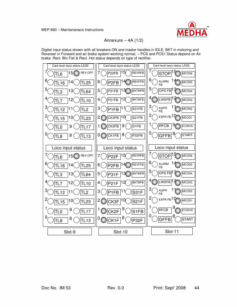
Doc No. :IM 53 Rev. 0.0 Print: Sept’ 2008 44
MEP-660 – Maintananace Instructions
Annexure – 4A (1/2)
Digital input status shown with all breakers ON and master handles in IDLE, BKT in motoring and Reverser in Forward and air brake system working normal. – PCS and PCS1 Status depend on Air brake. Rect. Blo Fail & Rect. Hot status depends on type of rectifier.
0
1
2
3
4
5
6
7
0
1
2
3
4
5
6
7
8
9
10
11
12
13
14
15
8
9
10
11
12
13
14
15
TL25
REV-OFF
TL13
TL17
TL10
TL64
TL23
TL2
TL17
TL23
TL2
TL10
REV-OFF
TL13
TL64
TL25
TL16
TL6
TL8
TL0
TL7
TL3
TL15
TL12
TL0
TL15
TL12
TL7
TL6
TL8
TL3
TL16
Card level input status LEDS
Loco input status LEDS
Slot-9
Loco input status LEDS
0
1
2
3
4
5
6
7
0
1
2
3
4
5
6
7
8
9
10
11
12
13
14
15
8
9
10
11
12
13
14
15
P2FB
P22FB
CK1FB
CK2FB
P21FB
P31FB
CK3FB
P1FB
CK2FB
CK3F
P1FB
P21FB
P22F
CK1FB
P31F
P2FB
REVFFB
REVRFB
P32F
S1FB
BKTBFB
BKTMFB
S21FB
S31FB
S1FB
S21F
S31F
BKTBFB
REVRFB
P32FB
BKTMFB
REVFFB
Card level input status LEDS
Slot-10
Loco input status LEDS
0
1
2
3
4
5
6
7
0
1
2
3
4
5
6
7
8
9
10
11
12
13
14
15
8
9
10
11
12
13
14
15
ALARM FB
STOP
GFFB
RFCB
LWSFB
OPS FB
EXPR FB
AGPR FB
RFCB
B
EXPR FB
AGPR FB
LWSFB
STOP
GFFB
OPS FB
ALARM FB
MCOS5
MCOS6
START
ECSRUN
MCOS3
MCOS4
MCOS1
MCOS2
ECSRUN
MCOS1
MCOS2
MCOS3
MCOS6
START
MCOS4
MCOS5
Card level input status LEDS
Slot-11
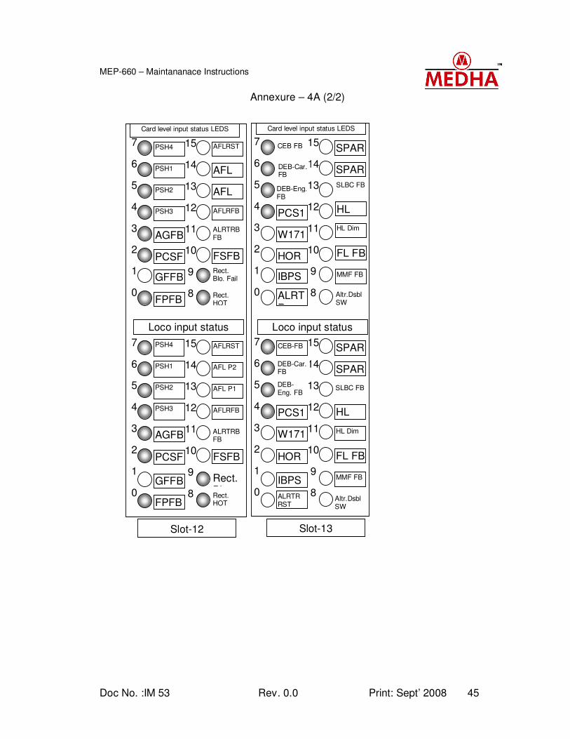
Doc No. :IM 53 Rev. 0.0 Print: Sept’ 2008 45
MEP-660 – Maintananace Instructions
Annexure – 4A (2/2)
Loco input status LEDS
0
1
2
3
4
5
6
7
0
1
2
3
4
5
6
7
8
9
10
11
12
13
14
15
8
9
10
11
12
13
14
15
PSH1
PSH4
FPFB
GFFB
PSH3
PSH2
PCSF
AGFB
GFFB
PCSF
AGFB
PSH3
PSH4
FPFB
PSH2
PSH1
AFL P2
AFLRST
Rect. HOT
Rect. Blo.
AFLRFB
AFL
FSFB
ALRTRB FB
Rect. Blo. Fail
FSFB
ALRTRB FB
AFLRFB
AFLRST
Rect. HOT
AFL P1
AFL P2
Card level input status LEDS
Slot-12 Slot-13
DEB-Eng. FB
Card level input status LEDS
0
1
2
3
4
5
6
7
0
1
2
3
4
5
6
7
8
9
10
11
12
13
14
15
8
9
10
11
12
13
14
15
DEB-Eng. FB
CEB FB
ALRTR RST
IBPS
PCS1
HORN
W171
IBPS
HOR
W171
PCS1
CEB-FB
ALRTR
DEB-Car. FB
SPAR
SPARE
Altr.Dsbl SW
MMF FB
FL FB
HL Dim
HL
SPARE
SLBC FB
SPARE
Altr.Dsbl SW
MMF FB
FL FB
HL Dim
HL Brit
SLBC FB
DEB-Car. FB
Loco input status LEDS
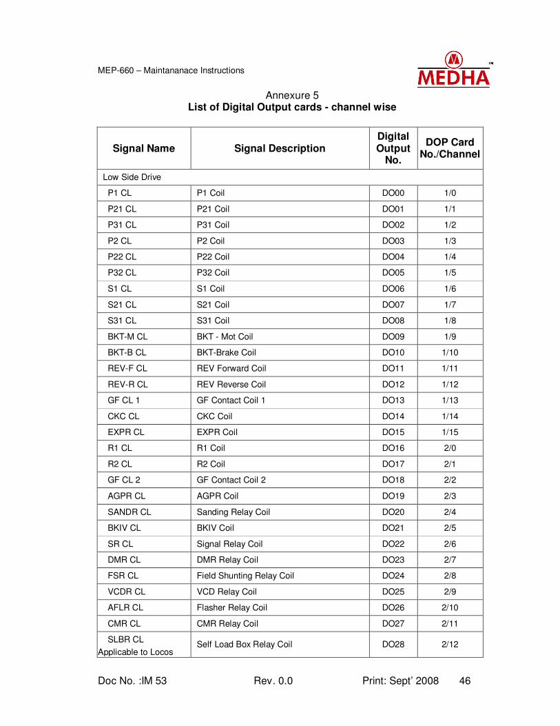
Doc No. :IM 53 Rev. 0.0 Print: Sept’ 2008 46
MEP-660 – Maintananace Instructions
Annexure 5 List of Digital Output cards - channel wise
Signal Name Signal Description Digital Output
No.
DOP Card No./Channel
Low Side Drive
P1 CL P1 Coil DO00 1/0
P21 CL P21 Coil DO01 1/1
P31 CL P31 Coil DO02 1/2
P2 CL P2 Coil DO03 1/3
P22 CL P22 Coil DO04 1/4
P32 CL P32 Coil DO05 1/5
S1 CL S1 Coil DO06 1/6
S21 CL S21 Coil DO07 1/7
S31 CL S31 Coil DO08 1/8
BKT-M CL BKT - Mot Coil DO09 1/9
BKT-B CL BKT-Brake Coil DO10 1/10
REV-F CL REV Forward Coil DO11 1/11
REV-R CL REV Reverse Coil DO12 1/12
GF CL 1 GF Contact Coil 1 DO13 1/13
CKC CL CKC Coil DO14 1/14
EXPR CL EXPR Coil DO15 1/15
R1 CL R1 Coil DO16 2/0
R2 CL R2 Coil DO17 2/1
GF CL 2 GF Contact Coil 2 DO18 2/2
AGPR CL AGPR Coil DO19 2/3
SANDR CL Sanding Relay Coil DO20 2/4
BKIV CL BKIV Coil DO21 2/5
SR CL Signal Relay Coil DO22 2/6
DMR CL DMR Relay Coil DO23 2/7
FSR CL Field Shunting Relay Coil DO24 2/8
VCDR CL VCD Relay Coil DO25 2/9
AFLR CL Flasher Relay Coil DO26 2/10
CMR CL CMR Relay Coil DO27 2/11
SLBR CL
Applicable to Locos Self Load Box Relay Coil DO28 2/12
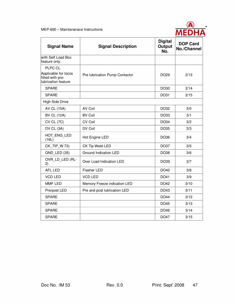
Doc No. :IM 53 Rev. 0.0 Print: Sept’ 2008 47
MEP-660 – Maintananace Instructions
Signal Name Signal Description Digital Output
No.
DOP Card No./Channel
with Self Load Box feature only.
PLPC CL
Applicable for locos fitted with pre-lubrication feature
Pre lubrication Pump Contactor DO29 2/13
SPARE DO30 2/14
SPARE DO31 2/15
High Side Drive
AV CL (15A) AV Coil DO32 3/0
BV CL (12A) BV Coil DO33 3/1
CV CL (7C) CV Coil DO34 3/2
DV CL (3A) DV Coil DO35 3/3
HOT_ENG_LED (16L)
Hot Engine LED DO36 3/4
CK_TIP_W 73) CK Tip Weld LED DO37 3/5
GND_LED (35) Ground Indication LED DO38 3/6
OVR_LD_LED (RL-2)
Over Load Indication LED DO39 3/7
AFL LED Flasher LED DO40 3/8
VCD LED VCD LED DO41 3/9
MMF LED Memory Freeze indication LED DO42 3/10
Pre/post LED Pre and post lubrication LED DO43 3/11
SPARE DO44 3/12
SPARE DO45 3/13
SPARE DO46 3/14
SPARE DO47 3/15
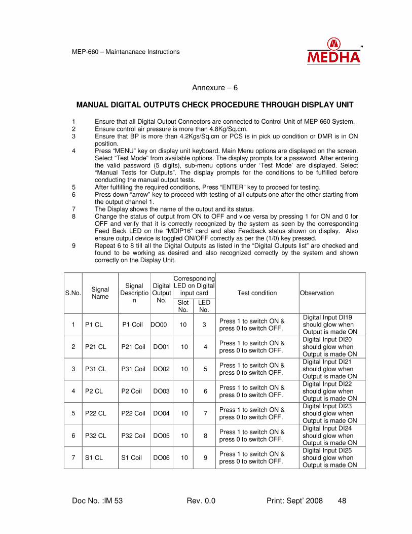
Doc No. :IM 53 Rev. 0.0 Print: Sept’ 2008 48
MEP-660 – Maintananace Instructions
Annexure – 6
MANUAL DIGITAL OUTPUTS CHECK PROCEDURE THROUGH DISPLAY UNIT
1 Ensure that all Digital Output Connectors are connected to Control Unit of MEP 660 System. 2 Ensure control air pressure is more than 4.8Kg/Sq.cm. 3 Ensure that BP is more than 4.2Kgs/Sq.cm or PCS is in pick up condition or DMR is in ON
position. 4 Press “MENU” key on display unit keyboard. Main Menu options are displayed on the screen.
Select “Test Mode” from available options. The display prompts for a password. After entering the valid password (5 digits), sub-menu options under ‘Test Mode’ are displayed. Select “Manual Tests for Outputs”. The display prompts for the conditions to be fulfilled before conducting the manual output tests.
5 After fulfilling the required conditions, Press “ENTER” key to proceed for testing. 6 Press down “arrow” key to proceed with testing of all outputs one after the other starting from
the output channel 1. 7 The Display shows the name of the output and its status. 8 Change the status of output from ON to OFF and vice versa by pressing 1 for ON and 0 for
OFF and verify that it is correctly recognized by the system as seen by the corresponding Feed Back LED on the “MDIP16” card and also Feedback status shown on display. Also ensure output device is toggled ON/OFF correctly as per the (1/0) key pressed.
9 Repeat 6 to 8 till all the Digital Outputs as listed in the “Digital Outputs list” are checked and found to be working as desired and also recognized correctly by the system and shown correctly on the Display Unit.
Corresponding LED on Digital
input card S.No. Signal Name
Signal Descriptio
n
Digital Output
No. Slot No.
LED No.
Test condition Observation
1 P1 CL P1 Coil DO00 10 3 Press 1 to switch ON & press 0 to switch OFF.
Digital Input DI19 should glow when Output is made ON
2 P21 CL P21 Coil DO01 10 4 Press 1 to switch ON & press 0 to switch OFF.
Digital Input DI20 should glow when Output is made ON
3 P31 CL P31 Coil DO02 10 5 Press 1 to switch ON & press 0 to switch OFF.
Digital Input DI21 should glow when Output is made ON
4 P2 CL P2 Coil DO03 10 6 Press 1 to switch ON & press 0 to switch OFF.
Digital Input DI22 should glow when Output is made ON
5 P22 CL P22 Coil DO04 10 7 Press 1 to switch ON & press 0 to switch OFF.
Digital Input DI23 should glow when Output is made ON
6 P32 CL P32 Coil DO05 10 8 Press 1 to switch ON & press 0 to switch OFF.
Digital Input DI24 should glow when Output is made ON
7 S1 CL S1 Coil DO06 10 9 Press 1 to switch ON & press 0 to switch OFF.
Digital Input DI25 should glow when Output is made ON
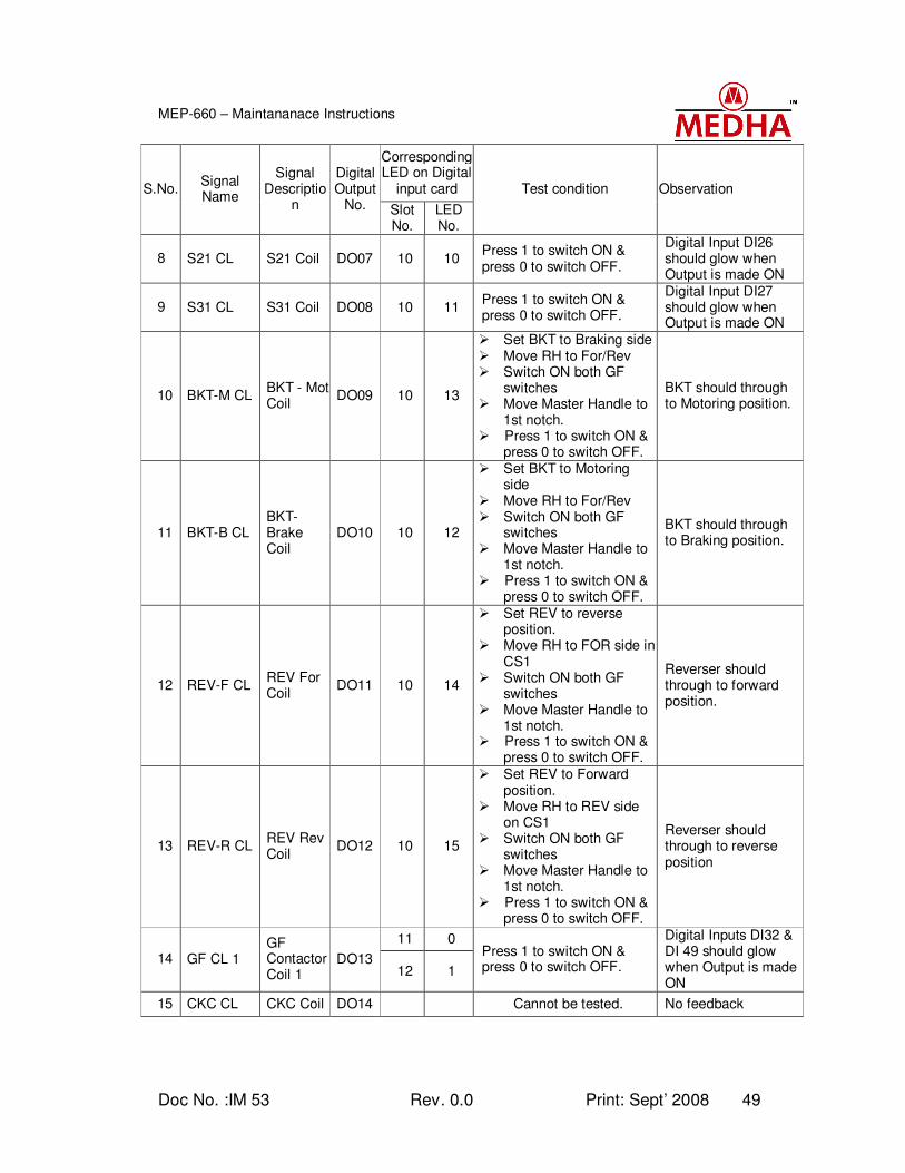
Doc No. :IM 53 Rev. 0.0 Print: Sept’ 2008 49
MEP-660 – Maintananace Instructions
Corresponding LED on Digital
input card S.No. Signal Name
Signal Descriptio
n
Digital Output
No. Slot No.
LED No.
Test condition Observation
8 S21 CL S21 Coil DO07 10 10 Press 1 to switch ON & press 0 to switch OFF.
Digital Input DI26 should glow when Output is made ON
9 S31 CL S31 Coil DO08 10 11 Press 1 to switch ON & press 0 to switch OFF.
Digital Input DI27 should glow when Output is made ON
10 BKT-M CL BKT - Mot Coil
DO09 10 13
Set BKT to Braking side Move RH to For/Rev Switch ON both GF
switches Move Master Handle to
1st notch. Press 1 to switch ON &
press 0 to switch OFF.
BKT should through to Motoring position.
11 BKT-B CL BKT-Brake Coil
DO10 10 12
Set BKT to Motoring side
Move RH to For/Rev Switch ON both GF
switches Move Master Handle to
1st notch. Press 1 to switch ON &
press 0 to switch OFF.
BKT should through to Braking position.
12 REV-F CL REV For Coil
DO11 10 14
Set REV to reverse position.
Move RH to FOR side in CS1
Switch ON both GF switches
Move Master Handle to 1st notch.
Press 1 to switch ON & press 0 to switch OFF.
Reverser should through to forward position.
13 REV-R CL REV Rev Coil
DO12 10 15
Set REV to Forward position.
Move RH to REV side on CS1
Switch ON both GF switches
Move Master Handle to 1st notch.
Press 1 to switch ON & press 0 to switch OFF.
Reverser should through to reverse position
11 0
14 GF CL 1 GF Contactor Coil 1
DO13 12 1
Press 1 to switch ON & press 0 to switch OFF.
Digital Inputs DI32 & DI 49 should glow when Output is made ON
15 CKC CL CKC Coil DO14 Cannot be tested. No feedback
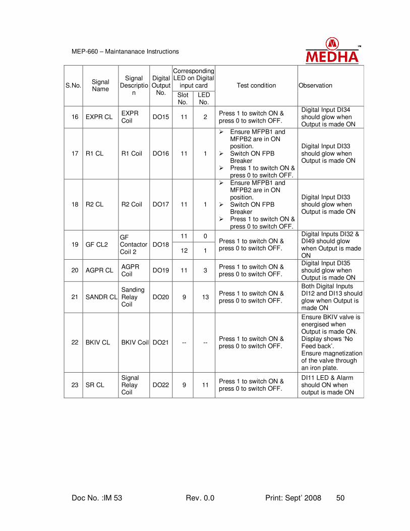
Doc No. :IM 53 Rev. 0.0 Print: Sept’ 2008 50
MEP-660 – Maintananace Instructions
Corresponding LED on Digital
input card S.No. Signal Name
Signal Descriptio
n
Digital Output
No. Slot No.
LED No.
Test condition Observation
16 EXPR CL EXPR Coil
DO15 11 2 Press 1 to switch ON & press 0 to switch OFF.
Digital Input DI34 should glow when Output is made ON
17 R1 CL R1 Coil DO16 11 1
Ensure MFPB1 and MFPB2 are in ON position.
Switch ON FPB Breaker
Press 1 to switch ON & press 0 to switch OFF.
Digital Input DI33 should glow when Output is made ON
18 R2 CL R2 Coil DO17 11 1
Ensure MFPB1 and MFPB2 are in ON position.
Switch ON FPB Breaker
Press 1 to switch ON & press 0 to switch OFF.
Digital Input DI33 should glow when Output is made ON
11 0
19 GF CL2 GF Contactor Coil 2
DO18 12 1
Press 1 to switch ON & press 0 to switch OFF.
Digital Inputs DI32 & DI49 should glow when Output is made ON
20 AGPR CL AGPR Coil
DO19 11 3 Press 1 to switch ON & press 0 to switch OFF.
Digital Input DI35 should glow when Output is made ON
21 SANDR CL Sanding Relay Coil
DO20 9 13 Press 1 to switch ON & press 0 to switch OFF.
Both Digital Inputs DI12 and DI13 should glow when Output is made ON
22 BKIV CL BKIV Coil DO21 -- -- Press 1 to switch ON & press 0 to switch OFF.
Ensure BKIV valve is energised when Output is made ON. Display shows ‘No Feed back’. Ensure magnetization of the valve through an iron plate.
23 SR CL Signal Relay Coil
DO22 9 11 Press 1 to switch ON & press 0 to switch OFF.
DI11 LED & Alarm should ON when output is made ON
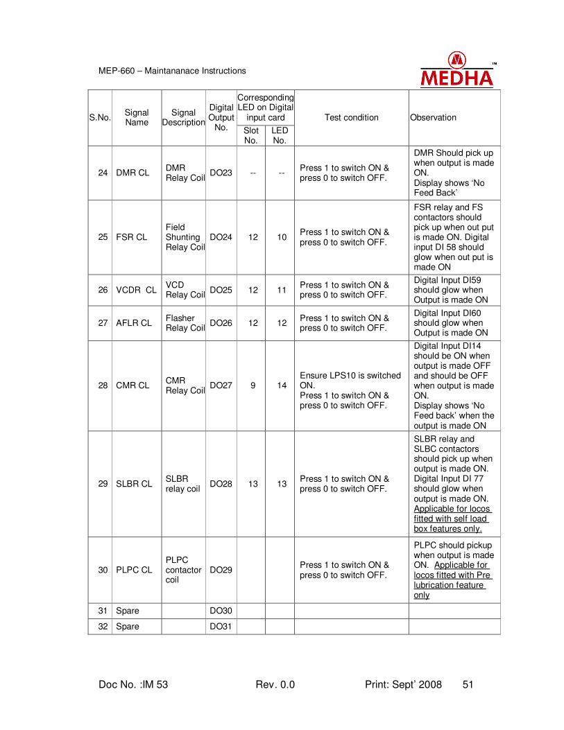
Doc No. :IM 53 Rev. 0.0 Print: Sept’ 2008 51
MEP-660 – Maintananace Instructions
Corresponding LED on Digital
input card S.No. Signal Name
Signal Description
Digital Output
No. Slot No.
LED No.
Test condition Observation
24 DMR CL DMR Relay Coil
DO23 -- -- Press 1 to switch ON & press 0 to switch OFF.
DMR Should pick up when output is made ON. Display shows ‘No Feed Back’
25 FSR CL Field Shunting Relay Coil
DO24 12 10 Press 1 to switch ON & press 0 to switch OFF.
FSR relay and FS contactors should pick up when out put is made ON. Digital input DI 58 should glow when out put is made ON
26 VCDR CL VCD Relay Coil
DO25 12 11 Press 1 to switch ON & press 0 to switch OFF.
Digital Input DI59 should glow when Output is made ON
27 AFLR CL Flasher Relay Coil
DO26 12 12 Press 1 to switch ON & press 0 to switch OFF.
Digital Input DI60 should glow when Output is made ON
28 CMR CL CMR Relay Coil
DO27 9 14
Ensure LPS10 is switched ON. Press 1 to switch ON & press 0 to switch OFF.
Digital Input DI14 should be ON when output is made OFF and should be OFF when output is made ON. Display shows ‘No Feed back’ when the output is made ON
29 SLBR CL SLBR relay coil
DO28 13 13 Press 1 to switch ON & press 0 to switch OFF.
SLBR relay and SLBC contactors should pick up when output is made ON. Digital Input DI 77 should glow when output is made ON. Applicable for locos fitted with self load box features only.
30 PLPC CL PLPC contactor coil
DO29 Press 1 to switch ON & press 0 to switch OFF.
PLPC should pickup when output is made ON. Applicable for locos fitted with Pre lubrication feature only
31 Spare DO30
32 Spare DO31
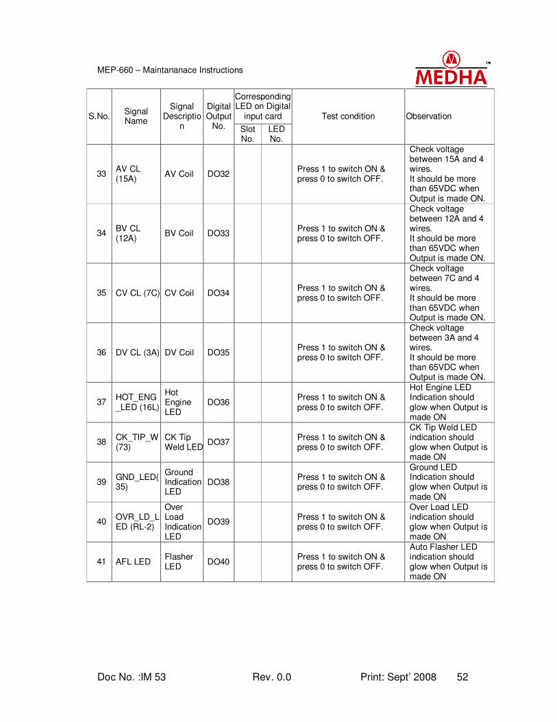
Doc No. :IM 53 Rev. 0.0 Print: Sept’ 2008 52
MEP-660 – Maintananace Instructions
Corresponding LED on Digital
input card S.No. Signal Name
Signal Descriptio
n
Digital Output
No. Slot No.
LED No.
Test condition Observation
33 AV CL (15A)
AV Coil DO32 Press 1 to switch ON & press 0 to switch OFF.
Check voltage between 15A and 4 wires. It should be more than 65VDC when Output is made ON.
34 BV CL (12A)
BV Coil DO33 Press 1 to switch ON & press 0 to switch OFF.
Check voltage between 12A and 4 wires. It should be more than 65VDC when Output is made ON.
35 CV CL (7C) CV Coil DO34 Press 1 to switch ON & press 0 to switch OFF.
Check voltage between 7C and 4 wires. It should be more than 65VDC when Output is made ON.
36 DV CL (3A) DV Coil DO35 Press 1 to switch ON & press 0 to switch OFF.
Check voltage between 3A and 4 wires. It should be more than 65VDC when Output is made ON.
37 HOT_ENG_LED (16L)
Hot Engine LED
DO36 Press 1 to switch ON & press 0 to switch OFF.
Hot Engine LED Indication should glow when Output is made ON
38 CK_TIP_W(73)
CK Tip Weld LED
DO37 Press 1 to switch ON & press 0 to switch OFF.
CK Tip Weld LED indication should glow when Output is made ON
39 GND_LED(35)
Ground Indication LED
DO38 Press 1 to switch ON & press 0 to switch OFF.
Ground LED Indication should glow when Output is made ON
40 OVR_LD_LED (RL-2)
Over Load Indication LED
DO39 Press 1 to switch ON & press 0 to switch OFF.
Over Load LED indication should glow when Output is made ON
41 AFL LED Flasher LED
DO40
Press 1 to switch ON & press 0 to switch OFF.
Auto Flasher LED indication should glow when Output is made ON
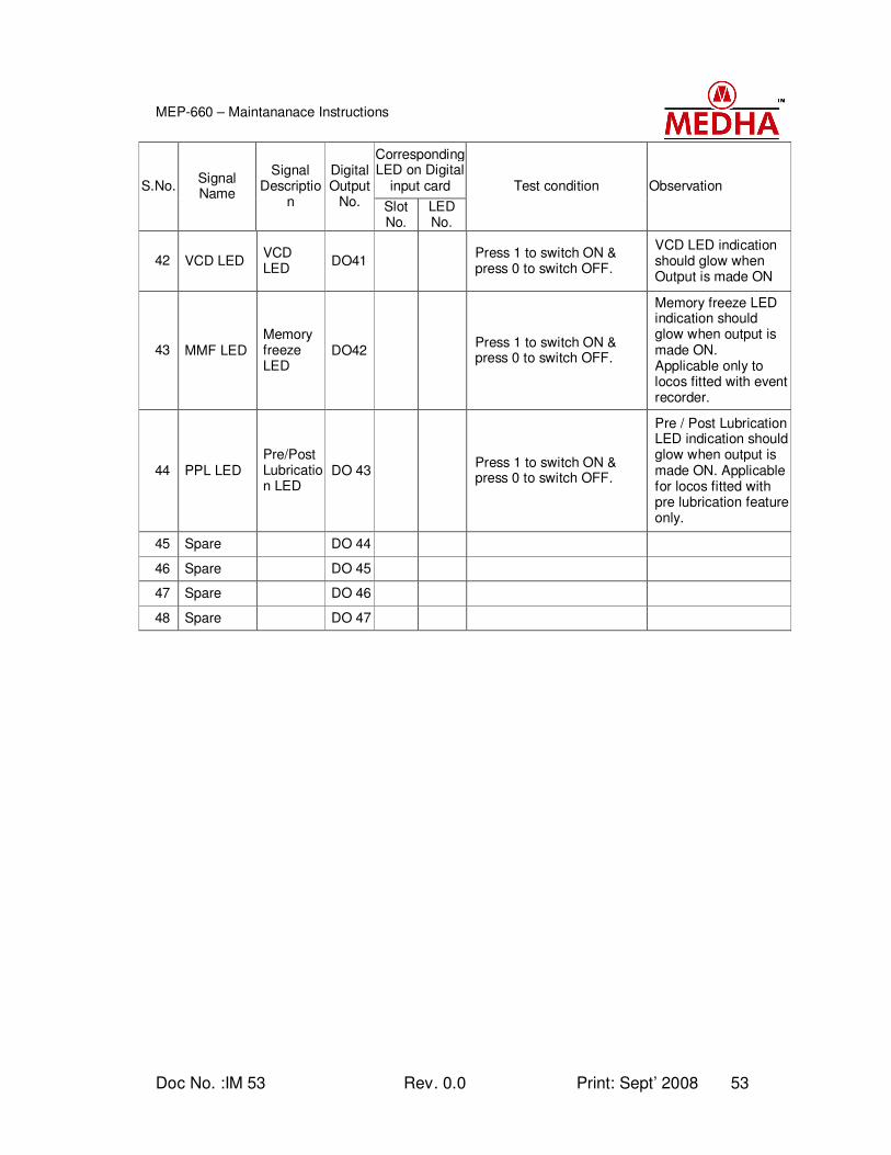
Doc No. :IM 53 Rev. 0.0 Print: Sept’ 2008 53
MEP-660 – Maintananace Instructions
Corresponding LED on Digital
input card S.No. Signal Name
Signal Descriptio
n
Digital Output
No. Slot No.
LED No.
Test condition Observation
42 VCD LED VCD LED
DO41
Press 1 to switch ON & press 0 to switch OFF.
VCD LED indication should glow when Output is made ON
43 MMF LED Memory freeze LED
DO42
Press 1 to switch ON & press 0 to switch OFF.
Memory freeze LED indication should glow when output is made ON. Applicable only to locos fitted with event recorder.
44 PPL LED Pre/Post Lubrication LED
DO 43
Press 1 to switch ON & press 0 to switch OFF.
Pre / Post Lubrication LED indication should glow when output is made ON. Applicable for locos fitted with pre lubrication feature only.
45 Spare DO 44
46 Spare DO 45
47 Spare DO 46
48 Spare DO 47
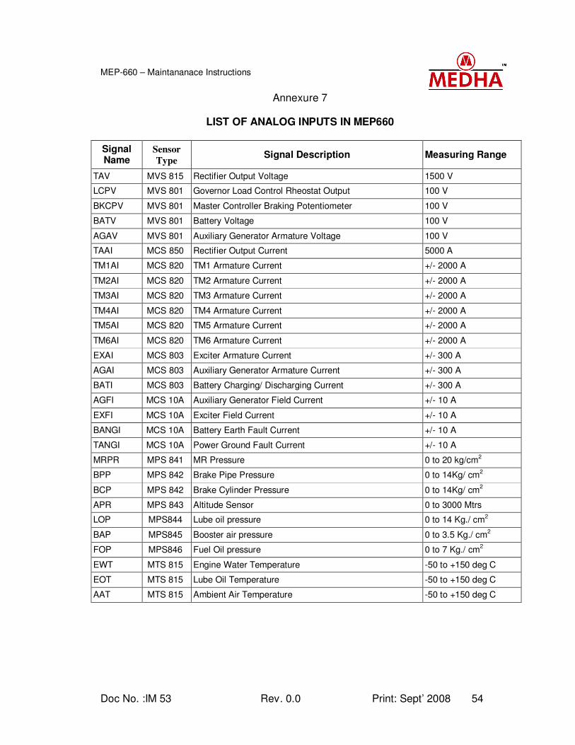
Doc No. :IM 53 Rev. 0.0 Print: Sept’ 2008 54
MEP-660 – Maintananace Instructions
Annexure 7
LIST OF ANALOG INPUTS IN MEP660
Signal Name
Sensor
Type Signal Description Measuring Range
TAV MVS 815 Rectifier Output Voltage 1500 V
LCPV MVS 801 Governor Load Control Rheostat Output 100 V
BKCPV MVS 801 Master Controller Braking Potentiometer 100 V
BATV MVS 801 Battery Voltage 100 V
AGAV MVS 801 Auxiliary Generator Armature Voltage 100 V
TAAI MCS 850 Rectifier Output Current 5000 A
TM1AI MCS 820 TM1 Armature Current +/- 2000 A
TM2AI MCS 820 TM2 Armature Current +/- 2000 A
TM3AI MCS 820 TM3 Armature Current +/- 2000 A
TM4AI MCS 820 TM4 Armature Current +/- 2000 A
TM5AI MCS 820 TM5 Armature Current +/- 2000 A
TM6AI MCS 820 TM6 Armature Current +/- 2000 A
EXAI MCS 803 Exciter Armature Current +/- 300 A
AGAI MCS 803 Auxiliary Generator Armature Current +/- 300 A
BATI MCS 803 Battery Charging/ Discharging Current +/- 300 A
AGFI MCS 10A Auxiliary Generator Field Current +/- 10 A
EXFI MCS 10A Exciter Field Current +/- 10 A
BANGI MCS 10A Battery Earth Fault Current +/- 10 A
TANGI MCS 10A Power Ground Fault Current +/- 10 A
MRPR MPS 841 MR Pressure 0 to 20 kg/cm2
BPP MPS 842 Brake Pipe Pressure 0 to 14Kg/ cm2
BCP MPS 842 Brake Cylinder Pressure 0 to 14Kg/ cm2
APR MPS 843 Altitude Sensor 0 to 3000 Mtrs
LOP MPS844 Lube oil pressure 0 to 14 Kg./ cm2
BAP MPS845 Booster air pressure 0 to 3.5 Kg./ cm2
FOP MPS846 Fuel Oil pressure 0 to 7 Kg./ cm2
EWT MTS 815 Engine Water Temperature -50 to +150 deg C
EOT MTS 815 Lube Oil Temperature -50 to +150 deg C
AAT MTS 815 Ambient Air Temperature -50 to +150 deg C
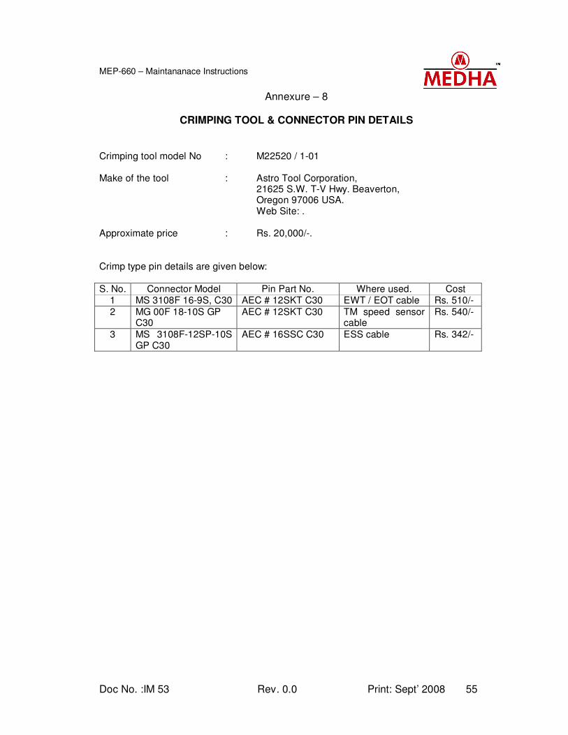
Doc No. :IM 53 Rev. 0.0 Print: Sept’ 2008 55
MEP-660 – Maintananace Instructions
Annexure – 8
CRIMPING TOOL & CONNECTOR PIN DETAILS
Crimping tool model No : M22520 / 1-01 Make of the tool : Astro Tool Corporation, 21625 S.W. T-V Hwy. Beaverton,
Oregon 97006 USA. Web Site: . Approximate price : Rs. 20,000/-. Crimp type pin details are given below:
S. No. Connector Model Pin Part No. Where used. Cost 1 MS 3108F 16-9S, C30 AEC # 12SKT C30 EWT / EOT cable Rs. 510/-
2 MG 00F 18-10S GP C30
AEC # 12SKT C30 TM speed sensor cable
Rs. 540/-
3 MS 3108F-12SP-10S GP C30
AEC # 16SSC C30 ESS cable Rs. 342/-