Embed Size (px)
Citation preview

Journal of Engineering Science and Technology Vol. 10, No. 7 (2015) 849 - 864 © School of Engineering, Taylor’s University
849
MICRONEEDLE STRUCTURE DESIGN AND OPTIMIZATION USING GENETIC ALGORITHM
N. A. ISMAIL1,*, S. C. NEOH
2, N. SABANI
1, B. N. TAIB
1
1School of Microelectronic Engineering, Universiti Malaysia Perlis,
Kampus Alam Pauh Putra, 02600 Pauh, Perlis, Malaysia 2Computational Intelligence Research Group,
Dept of Computing Science and Digital Technologies,
Faculty of Engineering and Environment,
University of Northumbria, Newcastle NE1, 8ST, UK
*Corresponding Author: [email protected]
Abstract
This paper presents a Genetic Algorithm (GA) based microneedle design and
analysis. GA is an evolutionary optimization technique that mimics the natural
biological evolution. The design of microneedle structure considers the shape of
microneedle, material used, size of the array, the base of microneedle, the lumen
base, the height of microneedle, the height of the lumen, and the height of the
drug container or reservoir. The GA is executed in conjunction with ANSYS
simulation system to assess the design specifications. The GA uses three
operators which are reproduction, crossover and mutation to manipulate the
genetic composition of the population. In this research, the microneedle is
designed to meet a number of significant specifications such as nodal
displacement, strain energy, equivalent stress and flow rate of the fluid / drug that flow through its channel / lumen. A comparison study is conducted to
investigate the design of microneedle structure with and without the
implementation of GA model. The results showed that GA is able to optimize
the design parameters of microneedle and is capable to achieve the required
specifications with better performance.
Keywords: Microneedle, MEMS, Optimization, Genetic Algorithm, Design and specifications.
1. Introduction
Micro-Electro-Mechanical System (MEMS), is a combination of mechanical
elements, sensors, actuators, and electronics on a common silicon substrate (or

850 N. A. Ismail et al.
Journal of Engineering Science and Technology July 2015, Vol. 10(7)
Nomenclatures
F1 Fitness value of total deformation of microneedle
F2 Fitness value of strain energy of microneedle
F3 Fitness value of equivalent stress of microneedle
F4 Fitness value of flow rate of fluid flow through lumen
Fm Fitness value for the specification m
Fmaverage Average value of specification m at Generation 1
FR Flow rate of fluid flow through lumen, µL/s
Ftot Normalized overall fitness function
Wm Weight for specification m
Abbreviations
bio-MEMS Biological MEMS
CBR Case-Based Reasoning
GA Genetic Algorithm
MEMS Micro-Electro-Mechanical System
MOGA Multi-Objective Genetic Algorithm
NiFe Nickel iron
TDD Transdermal drug delivery
other substrates) through microfabrication technology [1]. MEMS have been used
in various applications such as medical, automotive, aerospace, integrated circuit
design and etc. Nowadays, biological MEMS (bio-MEMS) have been the research
attention in the design of medical instruments.
The biological applications of MEMS (bio-MEMS) and microfluidics are
inextricably related for the reason that the majority of devices in systems for
biological and medical analysis work with samples in liquid form. Microfluidic
systems deal with the fluid flow in very small amounts, typically a few microlitres
(µL) in a miniaturized system [2]. Outside of biological analysis, microfluidic has
applications in chemical analysis, drug synthesis, drug delivery, and point-of-use
synthesis of harmful chemicals.
One micro fabricated invention that shows great promise for medical dealings
around the human race is the microneedle. These devices are typically designed
with two purposes which are drug delivery to the patient and blood extraction
from the patient for biosampling [3].Transdermal drug delivery (TDD) is refers to
the movement of pharmaceutical compound across the skin to reach the
systematic circulation for subsequent distribution in the human body [4]. Drug
delivery devices using MEMS technology are progressively being developed for
biomedical applications. The main advantage of the MEMS based drug delivery
system is the ease of mass fabrication of small feature sizes at low cost and
making such systems desirable for commercial applications [5].
Various studies have been conducted on new drug delivery methods using
emerging micro and nanotechnologies. The main focus of MEMS for drug
delivery has been towards the development of microneedles for minimally
invasive TDD applications [6]. MEMS technology brings new means for
biomedical field. One application of interest to the biomedical industry is the
development of microneedles.

Microneedle Structure Design and Optimization using Genetic Algorithm 851
Journal of Engineering Science and Technology July 2015, Vol. 10(7)
From literature, different shapes of microneedles have been developed in
MEMS technology using a variety of different materials, sizes, and fabrication
processes. The shape of the microneedle is very critical and important during
design and fabrication. Different designs of microneedles have been proposed and
fabricated such as cylindrical, canonical, pyramidal, candle, spike, spear, square,
pentagonal, hexagonal, octagonal and rocket shape [4, 6]. In order to design
painless microneedles, the design of microneedles needs to satisfy a number of
requirements such as nodal displacement, strain energy density, equivalent stress
and flow rate of drugs. Therefore, design parameter optimization is important to
achieve the output specifications of the microneedles.
Evolutionary computation has become an important area of research in the
21st century. It covers almost all fields such as engineering, science, education,
medicine, business, accounting, finance, marketing, economics, stock market and
law [7-13].
Genetic Algorithm (GA) is an evolutionary optimization technique that
mimics the natural biological evolution. In computer science, GA is well-known
for its capability to search for approximate solutions to the optimum [14] based on
the concepts of biological inheritance, mutation, selection and crossover.
The used of GA in optimizing and solving hard problems that require
intelligence from human perspective is very famous in many fields including
MEMS field. For instance, H. Bang et al. [15] present a novel method of
optimizing particle-suspended microfluidic channels using GA whereas Zhou
et al. [16] were the first to demonstrate that a Multi-Objective Genetic Algorithm
(MOGA) can synthesize MEMS resonators and produce new design structures.
Previous work by Cobb et al. [17] has shown that the integration of a Case-Based
Reasoning (CBR) knowledge base with a MOGA can increase the number of
optimal solutions generated for a given MEMS design problem.
In addition, Zhang et al. [18, 19] implemented a hierarchical MEMS synthesis
and optimization architecture, using a component-based genotype representation
and two levels of optimization: global GA and local gradient-based refinement.
Meanwhile, similar to the work proposed by Zhang [19], Wang et al. [20] conduct
a MEMS synthesis by utilizing bond graphs and genetic programming with a tree-
like structure of building blocks to incorporate knowledge into the evolutionary
process. In related research, Muhkerjee et al. [21] conducted work on MEMS
synthesis for accelerometers using parametric optimization of a pre-defined
MEMS topology. They expanded the design exploration within a
multidimensional grid in order to find the global optimal solution.
In this research, a GA-ANSYS design model is developed to assist the
structural design of microneedles. ANSYS is used to simulate the output
specifications of microneedles whereas GA is applied to optimize the design
parameters based on the simulated results from ANSYS.
2. Microneedle Design
The success of transdermal drug delivery has been severely limited by the
inability of most drugs to enter the skin at therapeutically useful rates. Recently,
the use of micron-scale needles in increasing skin permeability has been proposed

852 N. A. Ismail et al.
Journal of Engineering Science and Technology July 2015, Vol. 10(7)
and shown to dramatically increase transdermal delivery, especially for
macromolecules [3, 4, 6].
Using the tools of the microelectronics industry, microneedle has been
fabricated with a range of sizes, shapes and materials such as metals, silicon, silicon
dioxide, polymers, glass and other materials [22]. Figure 1 shows variety types of
microneedle developed from single crystal silicon reported by: a) Griss and
Stemme, 2003 [23]; b) Gardeniers et al., 2003 [24]; c) Stoeber and Liepmann, 2005
[25]; and nickel iron (NiFe) electroplating reported by d) McAllister et al., 1999 [26].
Fig. 1. Microneedles Developed from (a, b, c)
Single Crystal Silicon; and (d) Nickel Iron Electroplating [23-26].
Microneedle is a very useful drug delivery device. This device provides an
interface between the drug reservoir and the patient’s body for releasing or
extracting the fluid. The length of microneedle should be long enough that it
penetrates the epidermis and short enough not to reach the dermis, in order to
avoid pain. A minimum length of around 100 µm is necessary to penetrate the
stratum corneum of the skin [27, 28]. The suitable length of microneedle for drug
delivery is 100 µm to 300 µm, but for blood extraction the appropriate length of
microneedle is 1100 µm to 1600 µm [29]. This study is concentrating on the
microneedle for drug delivery purpose.
Microneedle can be integrated with micropump, biosensor, microelectronic
devices and microfluidic chips. Microneedles are promising microfabricated
devices for minimally invasive drug delivery applications. In order to be
minimally invasive, the needles are designed to be as small as possible. Needles
are also designed to be extremely sharp, with submicron tip radii. This allows the
needles to be effectively inserted into the skin. Microneedle offers an attractive
way for advanced drug delivery systems by mechanically penetrating the skin and
injecting drug just under the stratum corneum where it is rapidly absorbed by the
capillary bed into the bloodstream [30, 31].

Microneedle Structure Design and Optimization using Genetic Algorithm 853
Journal of Engineering Science and Technology July 2015, Vol. 10(7)
In general, a microneedle must be able to penetrate into the skin layer at least
40 µm so that it can be used effectively as a drug delivery. However, a
microneedle must not penetrate far beyond the thickness of the epidermis layer.
This is because the layer below the epidermis which is the dermis layer contains
blood vessels and nerve pain endings [3]. Therefore, one will feel hurt if the
needle penetrates to the dermis layer.
3. Determination of Microneedle Design Variables
Table 1 shows the design variables/parameters that are considered for the structural
optimization of microneedle in this research. There are eight design variables to be
manipulated and optimized. The variables involved are the shape of microneedle,
the material used, the array of the needles, microneedle base, lumen base, height of
microneedle, height of lumen and height of the drug container/reservoir. These
variables are manipulated to achieve the required microneedle specification as
shown in Table 2. Figure 2 shows four types of microneedle’s shape involved in
this study which are: a) canonical; b) pyramidal; c) hexagonal; and d) octagonal.
The dimension of microneedle viewed in cross-section is depicted in Fig. 3 while
the isometric view of microneedle design is shown in Fig. 4.
Table 1. Design Variables of Microneedle Structure.
Design
Variable Range
No. of
Range
Shape Canonical, Square base, Hexagonal base,
Octagonal base 4
Material Silicon, Polymeric, Stainless steel 3
Array 4x4, 6x6, 8x8, 10x10, 12x12 5
Microneedle
Base
60 µm, 65 µm, 70µm, 75 µm,
80 µm, 85 µm, 90 µm, 95 µm, 100 µm,
105 µm, 110 µm
11
Lumen Base 14µm, 16µm, 18µm, 20µm, 22µm,
24µm, 26µm, 28µm, 30µm, 32µm, 34µm 11
Microneedle
Height
150µm, 175µm, 200µm,225µm, 250µm,
275µm, 300µm 7
Lumen Height 150µm, 175µm, 200µm,225µm, 250µm,
275µm, 300µm 7
Drug Container
Height 1000µm, 1200µm, 1400µm, 1600µm 4
Table 2. The Required Specification
for the Microneedle Structure Optimization.
Parameters Range
Optimization Weight Min Max
Total Deformation
(µm) -
- Minimize 3
Strain Energy (pJ) - - Minimize 1
Equivalent Stress
(MPa) -
- Minimize 6
Flow Rate (µL/s) 5 - Maximize 10

854 N. A. Ismail et al.
Journal of Engineering Science and Technology July 2015, Vol. 10(7)
Fig. 2. Four Types of Microneedle’s Shape:
a) Canonical; b) Pyramidal; c) Hexagonal; and d) Octagonal.
Fig. 3. Dimensions of Microneedle View in Cross-section.
Fig. 4. Isometric View of Microneedle’s Design in this Research.
Height of
Microneedle
Height of
Microchannel
Diameter of
Microneedle's Base
Diameter of
Microchannel
Microneedle Structure Design and Optimization using Genetic Algorithm 855
Journal of Engineering Science and Technology July 2015, Vol. 10(7)
The optimization study for maximization of flow rate and minimization of
total deformation, strain energy and equivalent stress of microneedle are the main
objectives in this research. Simulations using ANSYS were used to solve for the
total deformation, strain energy density, equivalent stress and flow rate of
microneedle. This study considered that a microneedle would fail or undergo a
fracture when simulation results predict the stress is greater than or equal to the
yield strength of the microneedle material [32]. Hence, it is very important to
come out with a minimum value of the total deformation, strain energy density
and equivalent stress. Meanwhile, it is better for a microfluidic device to have a
higher flow rate so that the time taken to deliver drug to the body can be reduced.
As a result, a maximum flow rate is desired in this study.
The reason of putting the weight ratio in Table 2 is to indicate the importance
level of each of the parameter specification. In this case, the most important
parameter that needs to be achieved is the flow rate of the fluid flow. Therefore,
the weight ratio is being set to 10. Optimization weight for each specification in
Table 2 is assigned according to the expected design requirement.
Despite the eight design variables to be optimized, there are two constant
variables in this study. The constant variables are the pressure applied at the tip
of microneedle and the size of the microneedle array base. In this study, the
pressure is set to 3.18 MPa because according to [3, 33-34], human skin offers
resistance of 3.18 MPa during microneedle penetration. Hence, to overcome
this skin resistance, the microneedle must withstand the load more than 3.18
MPa. As for the size of the microneedle array base, it is set to 5000 µm ×
5000 µm × 50 µm.
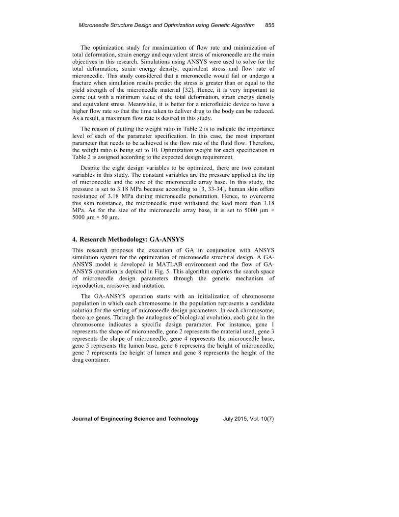
4. Research Methodology: GA-ANSYS
This research proposes the execution of GA in conjunction with ANSYS
simulation system for the optimization of microneedle structural design. A GA-
ANSYS model is developed in MATLAB environment and the flow of GA-
ANSYS operation is depicted in Fig. 5. This algorithm explores the search space
of microneedle design parameters through the genetic mechanism of
reproduction, crossover and mutation.
The GA-ANSYS operation starts with an initialization of chromosome
population in which each chromosome in the population represents a candidate
solution for the setting of microneedle design parameters. In each chromosome,
there are genes. Through the analogous of biological evolution, each gene in the
chromosome indicates a specific design parameter. For instance, gene 1
represents the shape of microneedle, gene 2 represents the material used, gene 3
represents the shape of microneedle, gene 4 represents the microneedle base,
gene 5 represents the lumen base, gene 6 represents the height of microneedle,
gene 7 represents the height of lumen and gene 8 represents the height of the
drug container.
856 N. A. Ismail et al.
Journal of Engineering Science and Technology July 2015, Vol. 10(7)
Fig. 5. GA-ANSYS Flow of Operation in this Study.
The generated chromosomes or candidate solutions are fed to the ANSYS
simulator to simulate the output specifications of the microneedle such as total
deformation, strain energy, equivalent stress and flow rate. These outputs are
then evaluated through the formulated fitness assignment function to measure
the proximity towards the targeted specifications in Table 2. Therefore, the
closer the achievement towards targeted output specifications, the better is the
fitness for the chromosome.

Microneedle Structure Design and Optimization using Genetic Algorithm 857
Journal of Engineering Science and Technology July 2015, Vol. 10(7)
After fitness evaluation, chromosomes will be selected for crossover and
mutation based on their fitness. The better the fitness, the higher is the
probability for the chromosome to be selected for reproduction of offspring to the
next GA generation.
Chromosomes that are selected for reproduction will be forwarded to two
genetic operators: crossover and mutation. Both crossover and mutation are
genetic operators used to increase the solution diversity. Crossover recombines
genetic information from two selected parent chromosomes. In this study, the
setting of some design variables in the selected chromosomes is swapped to
produce offspring solutions that inherit some genetic information from the
parents. As for mutation, the process involves random alteration of gene value in
a particular chromosome [35, 36]. Both genetic operators are conducted
according to the predefined crossover and mutation probability. The newly
generated offspring from crossover and mutation will then be fed to the ANSYS
simulation system for microneedle output performance evaluation. The
mechanisms of ANSYS simulation, fitness assignment, selection, and
reproduction are repeated until all the specifications are satisfied.
5. Experimental Setup
In this work, single-point crossover and mutation operations are used at the
beginning of the GA generation. Then, these points are modified according to the
suitable condition. A real-value encoded GA is used in this research to represent
the parameter setting of the microneedle. The GA parameters used in this research
are shown in Table 3.
Table 3. Parameters of the GA Setup.
Generation 0 1 2 3 4 5
Population Size 30 30 30 30 30 30
Generation Gap 0.9 0.9 0.9 0.9 0.9 0.9
Maximum Generation 100 100 100 100 100 100
Crossover Probability 0.8 0.7 0.7 0.1 0.3 0.2
Mutation Probability 0.2 0.3 0.3 0.9 0.7 0.8
No. of Crossover 1 2 2 1 1 2
No. of Mutation 1 2 2 3 3 2
The effectiveness of a GA is related to the ability of defining a “good” fitness
function [37]. Therefore, it is important to have an appropriate formulation of
fitness function. The main objective of this research is to optimize the overall
microneedle design performance in terms of the value of total deformation, strain
energy density, equivalent stress and the flow rate for fluid flow. From Table 2,
all specifications are to be minimized except for flow rate. There are four
specifications fitness in this study, F1, F2, F3, and F4. F1 is the fitness value for
total deformation (µm), F2 is the fitness value of strain energy (pJ), F3 is the
fitness value of equivalent stress (MPa), and F4 the fitness value of flow rate
(µL/s). Equation 1 shows the formulation for flow rate’s fitness value. Since the
flow rate is to be maximized and the minimum requirement for flow rate is 5
µL/s, the formulation of specification fitness for flow rate is based on the
achievement of minimum constraints. A penalty value of 100 is given when the
858 N. A. Ismail et al.
Journal of Engineering Science and Technology July 2015, Vol. 10(7)
constraint requirement is not satisfied. The reference value of the targeted flow
rate used in this study is 7 µL/s.
�4 = �100 + �5 − ���, ����� < 57 − ���, ����� > 5 (1)
Since different specification consists of different unit of measurement, bias
might exist when overall fitness is calculated in a weighted sum equation. As a
result, a normalized approach is employed to divide the fitness for each
specification with the average specification fitness. Equation 2 shows the
normalized overall fitness function:
���� = � �� �����������
�� ! , (2)
where:
Wm = Weight for specification m;
Fm = Fitness value for the specification m;
Fmaverage = Average value of specification m at Generation 1.
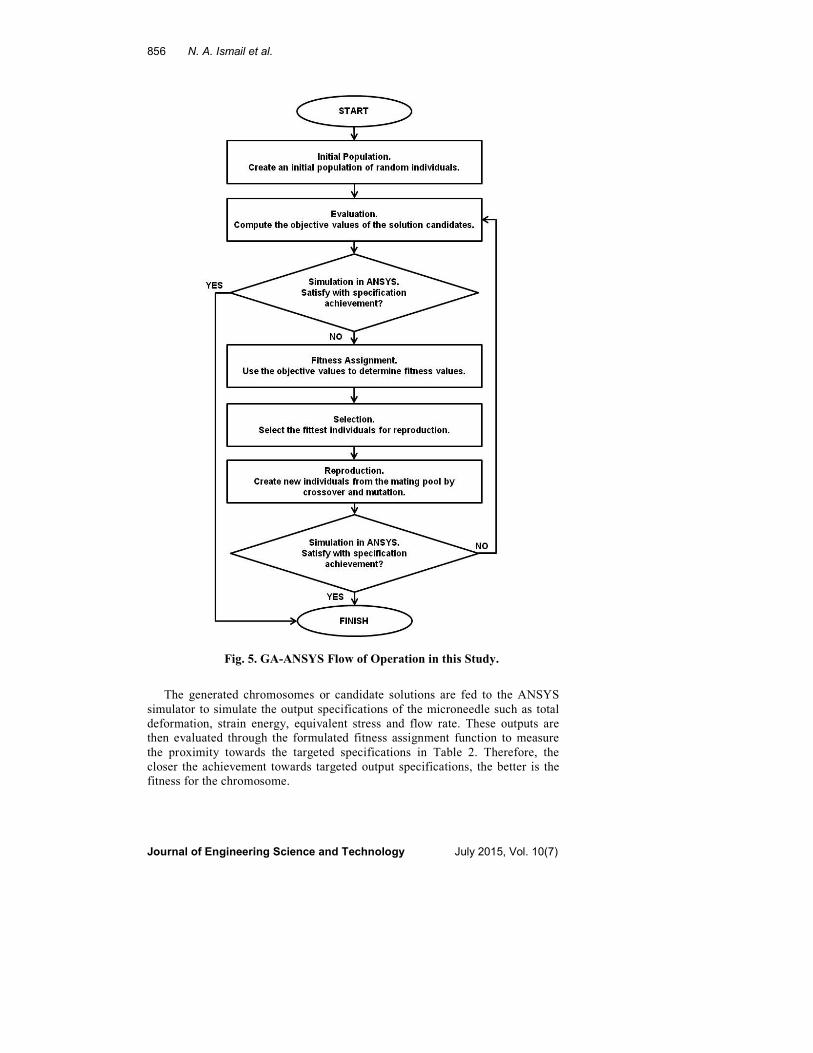
6. Result and Discussion
Based on the proposed GA approach, the optimized variables of the best individual
are given in Table 4 which shows the five best results that have been obtained in
MATLAB and ANSYS software. These variables have been chosen based on the
lowest fitness value. In this study, the lower the value of Ftot, the better the candidate
solution is. The GA have suggests a set of values for the design variables in Table 4
and the respective design performance in terms of total deformation, strain energy,
equivalent stress and flow rate in Table 5. From the results, it is observed that the
design setting is approaching the required specification for the microneedle
structure optimization. Figures 6-8 respectively show the results of total
deformation, strain energy and equivalent stress from ANSYS.
Table 4. Optimized Design Variables for
Microneedle Structure using GA (Five Best Individuals).
Design
Variable
GA Suggested Value
1 2 3 4 5
Shape Square Octagonal Square Octagonal Octagonal
Material Stainless
steel Silicon
Stainless
steel
Stainless
steel Silicon
Array 8x8 8x8 8x8 8x8 12x12
Microneedle
Base (µm) 90 90 85 90 70
Lumen Base
(µm) 26 26 24 26 18
Microneedle
Height (µm) 150 175 175 175 175
Lumen
Height (µm) 100 125 125 125 125
Drug
Container
Height (µm)
1200 1400 1600 1600 1000

Microneedle Structure Design and Optimization using Genetic Algorithm 859
Journal of Engineering Science and Technology July 2015, Vol. 10(7)
Table 5. Specification Achievement
after Optimization (Five Best Individuals).
Parameter GA Suggested Value
1 2 3 4 5
Total Deformation
(µm) 0.0075 0.0382 0.0185 0.0324 0.0611
Strain Energy (pJ) 1.1720 2.5961 1.9633 1.9165 3.2681
Equivalent Stress
(MPa) 11.3580 23.6040 23.7480 24.5550 35.4480
Flow Rate (µL/s) 5.2112 5.6287 5.1272 6.0174 5.1301
Fig. 6. Total Deformation for Best Microneedle’s Design.
Fig. 7. Strain Energy for Best Microneedle’s Design.

860 N. A. Ismail et al.
Journal of Engineering Science and Technology July 2015, Vol. 10(7)
Fig. 8. Equivalent Stress for Best Microneedle’s Design.
Table 6 shows the improvement of result obtained in this study by the
implementation of GA and the results without GA obtained from [38]. In [38],
only three design variables (microneedle shape, microneedle height and the
pressure applied to the microneedle) were considered for the output design
specification on total deformation, strain energy, and equivalent stress. However,
in this research, eight design variables of microneedle are optimized for four
design output specifications as listed in Table 4, and Table 5. From Table 6, it is
observed that the GA-based microneedle design achieve a better results in all
design specifications as compared to the previous study. The specifications to be
minimized such as total deformation, strain energy density and equivalent stress
are smaller than the result in [38]. Besides, the maximization of flow rate has also
been considered in the current study as compared to the previous. Five best
proposed candidate solutions of GA are depicted in Table 4. The results are all
better than the previous research in terms of output performance. Even though the
increase of flow rate to 6.0174 µL/s might lead to the increase of other design
output specification, the overall design performance are still better than the
previous research in [38]. Thus, the GA-based structural optimization of
microneedle is proven to outperform the conventional design without GA.
Table 6. Result Obtained in this Study and Previous Study [38].
Parameter Microneedle
Design with GA
Microneedle
Design without
GA [38]
Total Deformation (µm) 0.0075 1.01
Strain Energy Density (pJ) 1.1720 8.8089
Equivalent Stress (MPa) 11.3580 93.423
Flow Rate (µL/s) 5.2112 -
In the previous study [38], the analysis of microneedle structure has been
conducted based on simulation experience without the assistance of any
optimizer. The identification for the best microneedle structural setting is time
consuming and there is no directional search for a better setting. However, the

Microneedle Structure Design and Optimization using Genetic Algorithm 861
Journal of Engineering Science and Technology July 2015, Vol. 10(7)
proposal of GA-ANSYS optimization in this research provides an easier platform
to direct the search towards a better microneedle structural design.
7. Conclusion
MEMS designs that involve multiple variables are often difficult to be optimized.
The presented optimization algorithms in this paper can be used for a design of
microneedle structure or for improving an existing microneedle system. It can
also be used for micropump, microchannel, microreservoir, microvalve and other
mechanical system in MEMS. The presented optimization study shows the
integration of GA in ANSYS simulation. Eight design variables and four output
specifications are optimized. Improvements have been shown in terms of total
deformation, strain energy density, equivalent stress, and flow rate.
GAs are not guaranteed to achieve the total optimum, but they are generally
good at finding a satisfactory solution during a suitable amount of time. They are
generally designed to solve optimization problems. However, when cooperating
with other methods, that is usually called ‘hybrid’, it can also deal with problems
and constraints. Future work will focus on the hybridization of GA technique in
the optimization of more complex microneedle design.
Acknowledgement
The authors thank the School of Microelectronic Engineering, Universiti
Malaysia Perlis for MEMS laboratory facilities as well as to Malaysian
Government for funding the project based on MEMS; FRGS (No. 9003-00349)
and Artificial Intelligence; FRGS (No. 9003-00261).
References
1. Trimmer, W.S. (1997). Micromechanics and MEMS: Classic and seminal
papers to 1990. Wiley-IEEE Press. 978-0780310858.
2. Ashraf, M.W.; Tayyaba, S.; and Afzulpurkar, N. (2011). Micro
Electromechanical Systems (MEMS) based microfluidic devices for
biomedical applications. International Journal of Molecular Sciences, 12(6),
3648-3704.
3. Diehl, M.S. (2007). Design and Fabrication of out of plane Silicon Micro
needles with integrated Hydrophobic Micro channels. MSc. Thesis.
Department of Mechanical Engineering, Brigham Young University.
4. Ashraf, M.W.; Tayyaba, S.; Nisar, A.; Afzulpurkar, N.; Bodhale, D.W.;
Lomas, T.; Poyai, A.; and Tuantranont, A. (2010). Design, fabrication and
analysis of silicon hollow microneedles for transdermal drug delivery system
for Treatment of Hemodynamic Dysfunctions Cardiovascular. Journal of
Cardiovascular Engineering, 91-108.
5. Ashraf, M.W.; Tayyaba, S.; Afzulpurkar, N.; Nisar, A.; Bohez, E.L.J.;
Lomas, T.; and Tuantranont, A. (2011). Design, simulation and fabrication of
silicon microneedles for bio-medical applications. ECTI Transactions on
Electrical Engineering, Electronics, and Communications, 9(1), 83-91.

862 N. A. Ismail et al.
Journal of Engineering Science and Technology July 2015, Vol. 10(7)
6. Ashraf, M.W.; Tayyaba, S.; Afzulpurkar, N.; and Nisar, A. (2010).
Fabrication and analysis of tapered tip silicon microneedles for MEMS based
drug delivery system. Sensor and Transducer Journal, 122(11), 158-173.
7. Halal, W.E. (2003). Artificial intelligence is almost here. On the horizon. The
Strategic Planning Resource for Education Professionals, 11(2), 37-38.
8. Masnikosa, V.P. (1998). The fundamental problem of an artificial
intelligence realisation. Kybernetes, 27(1), 71-80.
9. Metaxiotis, K.; Ergazakis, K.; Samouilidis, E.; and Psarras, J. (2003).
Decision support through knowledge management: the role of the artificial
intelligence. Information Management & Computer Security, 11(5), 216-221.
10. Raynor, W.J. (2000). The international dictionary of artificial intelligence.
Reference Reviews.
11. Stefanuk, V.L.; and Zhozhikashvili, A.V. (2002). Productions and rules in
artificial intelligence. Kybernetes: The International Journal of Systems &
Cybernetics, 31(6), 817-826.
12. Tay, D.P.H.; and Ho, D.K.H. (1992). Artificial intelligence and the mass
appraisal of residential apartments. Journal of Property Valuation and
Investment, 10(2), 525-540.
13. Wongpinunwatana, N.; Ferguson, C.; and Bowen, P. (2000). An experimental
investigation of the effects of artificial intelligence systems on the training of
novice auditors. Managerial Auditing Journal, 5(6), 306-318.
14. Marcyzk, A. (2004). Genetic algorithms and evolutionary computation.
Retrieved June 26, 2014, from http://www.talkorigins.org/faqs/genalg/
genalg.html.
15. Bang, H.; Lee, W.G.; Park, J.; Yun, H.; Min, J.; and Han, D.C. (2009).
Optimal microchannel design using genetic algorithms. Journal of
Mechanical Science and Technology, 23(5), 1500-1507.
16. Zhou, N.; Zhu, B.; Agogino, A.M.; and Pister, K.S.J. (2001). Evolutionary
synthesis of MEMS (Micro Electronic Mechanical Systems) design.
Proceeding of the Artificial Neural Networks in Engineering Conference,
197-202.
17. Cobb, C.L.; Zhang, Y.; and Agogino, A.M. (2007). MEMS design synthesis:
integrating case-based reasoning and multi-objective genetic algorithms.
Proceeding of SPIE International Society of Optical Engineering Smart
Structures, Devices, and Systems III, 6414(19), 1-11.
18. Zhang, Y.; Kamalian, R.; Agogino, A.M.; and Séquin, C.H. (2005).
Hierarchical MEMS synthesis and optimization. Proceeding of SPIE Smart
Structures and Materials 2005, Smart Electronics, MEMS, BioMEMS, and
Nanotechnology, 5763, 96-106.
19. Zhang, Y.; Kamalian, R.; Agogino, A.M.; and Séquin, C.H. (2006). Design
synthesis of micro electro mechanical systems using genetic algorithms with
component-based genotype representation. Proceeding of Genetic and
Evolutionary Computation Conference, 731-738.
20. Wang, J.; Fan, Z.; Terpenny, J.P.; and Goodman, E.D. (2005). Knowledge
interaction with genetic programming in mechatronics systems design using
bond graphs. IEEE Transactions on System, Man, and Cybernetics-Part C:
Applications and Reviews, 35(2), 172-182.

Microneedle Structure Design and Optimization using Genetic Algorithm 863
Journal of Engineering Science and Technology July 2015, Vol. 10(7)
21. Mukherjee, T.; Zhou, Y.; and Fedder, G. (1999). Automated optimal
synthesis of micro accelerometers. Proceedings of the 12th IEEE
International Conference on Micro Electro Mechanical Systems (MEMS'99),
326-331.
22. Tabassum, N.; Sofi, A.; and Khuroo, T. (2001). Microneedle technology: a
new drug delivery system. International Journal of Research in
Pharmaceutical and Biomedical Sciences, 2(1), 59-62.
23. Griss, P.; and Stemme, G. (2003). Side-opened out-of-plane microneedles for
microfluidic transdermal liquid transfer. Journal of Microelectromechanical
Systems, 12(3), 296-301.
24. Gardeniers, H.J.G.E.; Luttge, R.; Berenschot, E.J.W.; Boer, M.J.D.;
Yeshurun, S.Y.; Hefetz, M.; van’t Oever, R and van den Berg, A. (2003).
Silicon micromachined hollow microneedles for transdermal liquid transport.
Journal of Microelectromechanical Systems, 12(6), 855-862.
25. Stoeber, B.; and Liepmann, D. (2005). Arrays of hollow out-of-plane
microneedles for drug delivery. Journal of Microelectromechanical Systems,
14(3), 472-479.
26. McAllister, D.V.; Cros, F.; Davis, S.P.; Matta, L.M.; Prausnitz, M.R.; and
Allen, M.G. (1999). Three-dimensional hollow microneedle and microtube
arrays. Transducers 99, 10th International Conference of Solid-State Sensors
and Actuators, 1089-1101.
27. Toon, J. (1998). Taking the ‘ouch’ out of needles arrays of micron scale
‘microneedles’ offer new technique for drug delivery. Retrieved June 22,
2014, from http://gtresearchnews.gatech.edu/newsrelease/NEEDLES.html.
28. Morrison, J.C.; and Moore, C.G. (2009). Microneedle for injection of ocular
blood vessels. Patent US 5, 364-374.
29. Ashraf, M.W.; Tayyaba, S.; Afzulpurkar, N.; Nisar, A.; Punyasai, C.; Saejok,
K.; Supadech, J.; Atthi, N.; Hruanun, C.; and Poyai, A. (2010). Optimization
of fabrication process for MEMS based microneedles using ICP etching
technology. Advanced Materials Research, 403, 4611-4616.
30. Brazzle, J.; Pauptsky I.; and Frazier, A.B. (1999). Microneedle: a new drug
delivery technology. IEEE Engineering in Medicine and Biology Magazine,
53-58.
31. Brazzle, D.; Bartholomeuseuz, R.; Davies, J.; Andrade, R.A.; Wageman, V.;
and Frazier, A.B.; (2000). Drug delivery in MEMS. Proceedings Solid State
Sensor and Actuator Workshop, Hilton Head, 199-202.
32. Lhernould, M.S.; and Delchambre, A. (2011). Innovative design of hollow
polymeric microneedles for transdermal drug delivery. Microsystem
Technology, 17(10), 1675-1682.
33. Wilke, N. (2005). Silicon microneedle electrode array with temperature
monitoring for electroporation. Sensors and Actuators, 123, 319-325.
34. Wang, X. (2006). A novel fabrication approach for microneedles using
silicon micromachining technology. 1st IEEE International Conference on
NEMS, 545-549.
35. Saeh, I.S.; and Khairuddin, A. (2009). Implementation of artificial
intelligence techniques for steady state security assessment in pool market.
International Journal of Engineering (IJE), 3(1), 1-11.

864 N. A. Ismail et al.
Journal of Engineering Science and Technology July 2015, Vol. 10(7)
36. Hadas, Z.; Kurfurst, J.; Ondrusekand, C.; and Singule, V. (2012). Artificial
intelligence based optimization for vibration energy harvesting applications.
Microsystem Technology, 18(7), 1003-1014.
37. Enami, N.; Moghadam, R.A.; and Haghighat, A. (2010). A survey on
application of neural networks in energy conservation of wireless sensor
networks. Communications in Computer and Information Science, 84, 283-294.
38. Ismail, N.A.; Neoh, S.C.; and Sabani, N. (2012). Design and analysis of
microneedles in microfluidic channel for drug delivery system. The 2nd
International Malaysia-Ireland Joint Symposium on Engineering, Science
and Business, 12-21.