Embed Size (px)
Citation preview

AU9200 COLD FOGGING
MACHINE
Operator's Handbook
and
Parts Catalogue Micron Sprayers Limited Bromyard Industrial Estate Bromyard Herefordshire HR7 4HS United Kingdom Telephone: +44 (0) 1885 482397 Fax: +44 (0) 1885 483043 E-mail: [email protected] Web site: www.micron.co.uk
Iss 4W 05/2006
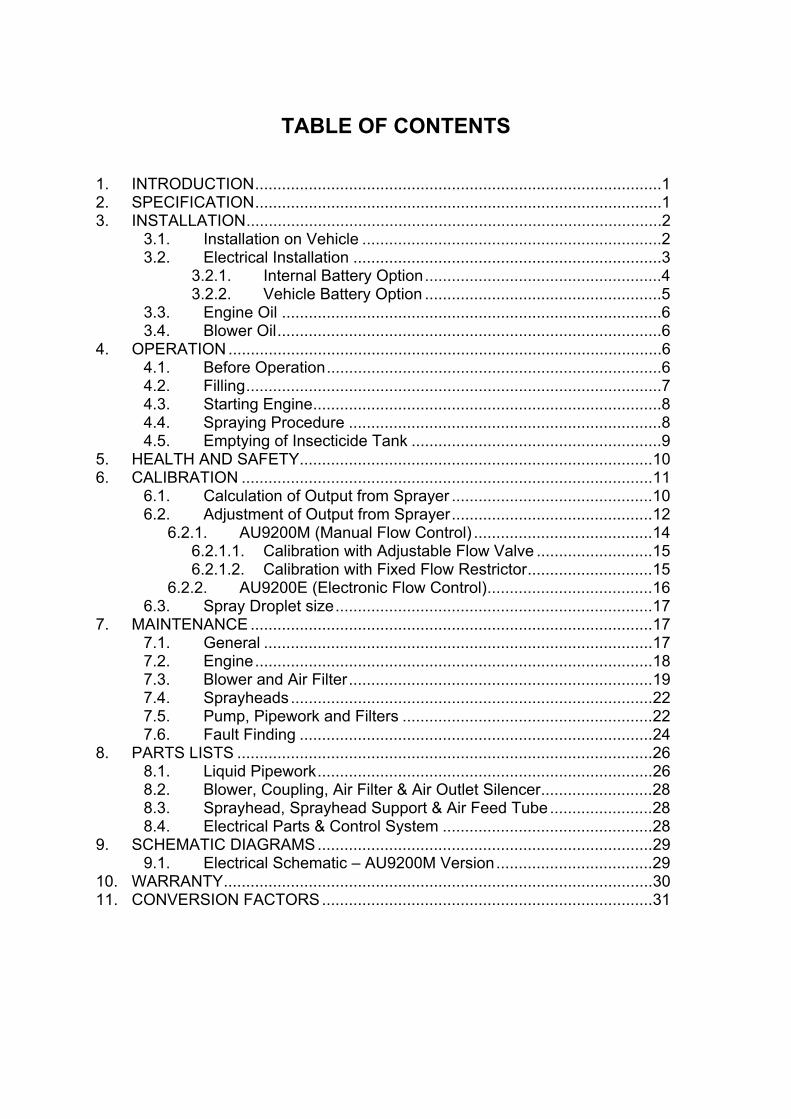
TABLE OF CONTENTS
1. INTRODUCTION...........................................................................................1 2. SPECIFICATION...........................................................................................1 3. INSTALLATION.............................................................................................2
3.1. Installation on Vehicle ...................................................................2 3.2. Electrical Installation .....................................................................3
3.2.1. Internal Battery Option.....................................................4 3.2.2. Vehicle Battery Option .....................................................5
3.3. Engine Oil .....................................................................................6 3.4. Blower Oil......................................................................................6
4. OPERATION.................................................................................................6 4.1. Before Operation...........................................................................6 4.2. Filling.............................................................................................7 4.3. Starting Engine..............................................................................8 4.4. Spraying Procedure ......................................................................8 4.5. Emptying of Insecticide Tank ........................................................9
5. HEALTH AND SAFETY...............................................................................10 6. CALIBRATION ............................................................................................11
6.1. Calculation of Output from Sprayer .............................................10 6.2. Adjustment of Output from Sprayer.............................................12
6.2.1. AU9200M (Manual Flow Control) ........................................14 6.2.1.1. Calibration with Adjustable Flow Valve ..........................15 6.2.1.2. Calibration with Fixed Flow Restrictor............................15
6.2.2. AU9200E (Electronic Flow Control).....................................16 6.3. Spray Droplet size.......................................................................17
7. MAINTENANCE ..........................................................................................17 7.1. General .......................................................................................17 7.2. Engine.........................................................................................18 7.3. Blower and Air Filter....................................................................19 7.4. Sprayheads.................................................................................22 7.5. Pump, Pipework and Filters ........................................................22 7.6. Fault Finding ...............................................................................24
8. PARTS LISTS .............................................................................................26 8.1. Liquid Pipework...........................................................................26 8.2. Blower, Coupling, Air Filter & Air Outlet Silencer.........................28 8.3. Sprayhead, Sprayhead Support & Air Feed Tube.......................28 8.4. Electrical Parts & Control System ...............................................28
9. SCHEMATIC DIAGRAMS...........................................................................29 9.1. Electrical Schematic – AU9200M Version...................................29
10. WARRANTY................................................................................................30 11. CONVERSION FACTORS..........................................................................31
MICRONAIR AU9200 COLD FOGGING MACHINE
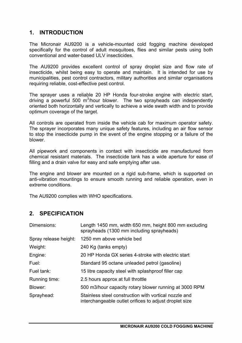
1. INTRODUCTION The Micronair AU9200 is a vehicle-mounted cold fogging machine developed specifically for the control of adult mosquitoes, flies and similar pests using both conventional and water-based ULV insecticides. The AU9200 provides excellent control of spray droplet size and flow rate of insecticide, whilst being easy to operate and maintain. It is intended for use by municipalities, pest control contractors, military authorities and similar organisations requiring reliable, cost-effective pest control. The sprayer uses a reliable 20 HP Honda four-stroke engine with electric start, driving a powerful 500 m3/hour blower. The two sprayheads can independently oriented both horizontally and vertically to achieve a wide swath width and to provide optimum coverage of the target. All controls are operated from inside the vehicle cab for maximum operator safety. The sprayer incorporates many unique safety features, including an air flow sensor to stop the insecticide pump in the event of the engine stopping or a failure of the blower. All pipework and components in contact with insecticide are manufactured from chemical resistant materials. The insecticide tank has a wide aperture for ease of filling and a drain valve for easy and safe emptying after use. The engine and blower are mounted on a rigid sub-frame, which is supported on anti-vibration mountings to ensure smooth running and reliable operation, even in extreme conditions. The AU9200 complies with WHO specifications. 2. SPECIFICATION Dimensions: Length 1450 mm, width 650 mm, height 800 mm excluding
sprayheads (1300 mm including sprayheads) Spray release height: 1250 mm above vehicle bed Weight: 240 Kg (tanks empty) Engine: 20 HP Honda GX series 4-stroke with electric start Fuel: Standard 95 octane unleaded petrol (gasoline) Fuel tank: 15 litre capacity steel with splashproof filler cap Running time: 2.5 hours approx at full throttle Blower: 500 m3/hour capacity rotary blower running at 3000 RPM Sprayhead: Stainless steel construction with vortical nozzle and
interchangeable outlet orifices to adjust droplet size
2
MICRONAIR AU9200 COLD FOGGING MACHINE
Spray droplet size: Adjustable 15 – 25 μm VMD for oil-based ULV insecticides
Adjustable 25 – 60 μm VMD for water-based ULV insecticides
(measured with typical formulations) Output rate: Adjustable 0 – 1.0 l/min (total from both sprayheads) Output adjustment: By adjustable valve or interchangeable fixed restrictor
orifices (AU9200M) or optional cab-mounted electronic control (AU9200E)
Insecticide tank: 50 litre capacity HDPE construction with 180 mm filling aperture
Electrical power: 12 VDC @ 5 A (spraying), 70 A (engine start) Power source: 12 V vehicle battery or integral 12 V 45 Ah battery (charged
from engine of sprayer) Control box: Mounted in cab of vehicle Switches: Electrical master Engine throttle Insecticide pump Indicators: Power on Blower operating Pump on Insecticide pressure Mounting on vehicle: By M10 bolts through universal mounting base 3. INSTALLATION 3.1. Installation on Vehicle The AU9200 is designed for installation on the bed of a pick-up truck, small lorry or similar vehicle. It may also mounted on a trailer towed behind a vehicle. The procedure to mount the sprayer is as follows: 1. Position the sprayer on the bed of the vehicle so that it is as far back as possible
without the frame of the machine touching the tail-board. The sprayheads should protrude slightly behind the vehicle if possible. The sprayer can be positioned either in the centre of the bed of the vehicle or can be moved to one side to allow easy access and space to carry additional items.
IMPORTANT: If installing the sprayer on a light-weight vehicle or trailer, it must be positioned such the weight of the machine does not affect the stability or roadworthiness of the vehicle.
2. Adjust the position of the sprayer so that the mounting holes in the base-plate
align with suitable positions to drill holes in the vehicle bed. If the bed is made

3
MICRONAIR AU9200 COLD FOGGING MACHINE
from corrugated metal, the base plate should be in contact with the tops of the corrugations adjacent to the mounting holes. If corrugations or other obstructions on the vehicle bed prevent sufficient contact with the sprayer base plate, a sheet of waterproof plywood at least 12 mm (1/2”) thick or steel at least 3 mm (1/8”) thick can be fitted under the machine.
3. Mark and drill at least four 11 mm (7/16”) diameter holes in the vehicle bed to
align with holes in the base plate. Wherever possible, choose holes adjacent to the anti-vibration mounts securing the engine mount to the base plate. There must be at least one hole at each end of the base plate on each side of the sprayer. (Note that access to one hole at the front of the base plate is through a cut-out in the battery tray at the rear of the machine.)
IMPORTANT: Before drilling any holes, ensure that the area under the vehicle bed is clear of fuel lines, tanks, electrical items or structure that could be damaged or weakened by drilling.
4. Bolt the sprayer to the bed of the vehicle with the M10 bolts, nuts and washers
supplied (or use longer bolts if necessary). The square steel packers (5992) provided with the kit should be used under the nuts to spread the load on the underside of the bed. (Alternative packers may be made and used if necessary.)
3.2. Electrical Installation
Fig. 1 – Control Box in Cab of Vehicle
4
MICRONAIR AU9200 COLD FOGGING MACHINE
1. Position the control box in the vehicle cab (see Fig. 1). This should be adjacent to the driver or spray operator’s seat. Secure the box in position with the self-adhesive Velcro strips provided or by bolts through the mounting holes in the corners of the box. (Remove the lid of the box to gain access to the mounting holes.)
2. Route the cable from the control box to the rear of the vehicle. Whenever
possible, pass the cable through existing holes provided for electrical wiring. If necessary, new holes should be drilled for the cable. All holes should be protected with plastic or rubber bushings to prevent chafing of the cable. The plug may be removed from the cable if it will not pass through a hole. The connections inside the plug are made with screw terminals – refer to Fig. ## for details of wire colours and connector pin numbers.
IMPORTANT: The box and cable must be positioned so as not to obstruct the movement of occupants of the cab, not to obstruct the vision of the driver and not to cause a hazard in the event of an accident.
3. Insert the plug on the control box cable into the socket on the junction box on the
right-hand side of the sprayer frame. Secure the plug with its threaded locking ring.
The AU9120 sprayer is available with two options for its electrical power: an internal battery or operation from the vehicle battery. Note that the power source is set at the factory and cannot be changed by the user. Installation procedures are as follows: 3.2.1. Internal Battery Option With this option, the engine starter motor and the electrical system of the sprayer are powered by an internal battery. The battery is charged by a generator on the engine of the sprayer. There is no connection to the electrical system of the vehicle. International transport regulations prohibit the shipment of lead-acid batteries to many destinations, so it is likely that the sprayer will be supplied without a battery. If this is the case, it is the customer’s responsibility to purchase and fit a suitable battery. The battery specification is as follows:
Type: Lead-acid Voltage: 12 V Capacity: 45 AH minimum Dimensions: 200 mm (7.9”) L x 170 mm (6.7”) W x 175 mm (6.9”) H Mounting: By lugs at base of battery at ends Terminals: 18 mm (0.7”) diameter posts (batteries with lugs can
be used if the clamps on the battery cables are changed to ring terminals).
Typical part numbers: BBMS 063, DIN 544-34
5
MICRONAIR AU9200 COLD FOGGING MACHINE
The battery should be filled (if necessary) with battery acid diluted with de-ionised water to the manufacturer’s specification, charged and installed as follows: 1. Remove the two screws securing the battery retaining plate nearest the side of
the sprayer and remove the plate. 2. Fit the battery so that the terminals are towards the rear of the vehicle and the
inboard battery mounting lug is under the retaining plate. 3. Re-fit the outboard battery retaining plate so that it grips the securing lug of the
battery, using the original screws. 4. Connect the clamp of the red battery lead to the positive (+) battery terminal post
and then the clamp of the black lead to the negative (-) post. 5. Cover both battery terminals with a layer of petroleum jelly (Vaseline). 6. Fit the protective cover over the positive battery terminal. 3.2.2. Vehicle Battery Option With this option, the engine starter motor and electrical system of the sprayer are powered by the battery of the vehicle. This system can only be used on vehicles with standard 12 V negative earth (ground) electrical systems. There is no generator on the engine of the sprayer. The sprayer is connected to the vehicle electrical system as follows: 1. Unplug the fuse assembly EX6329/60 from the end of the red and black battery
wires (note that the black plastic locking tab on one side of the connector must be pressed down before pulling it apart).
2. Route the red and black wires to the vehicle battery. Ensure that these wires are
protected by plastic or rubber bushes if they pass through holes or adjacent to sharp edges.
3. Connect the ring tag on the red wire of the fuse assembly to the positive (+)
battery terminal. 4. Connect the ring tag on the black wire of the fuse assembly to the negative (-)
battery terminal or the vehicle ground adjacent to the battery. 5. Plug the connector on the sprayer battery cable into the socket on the fuse
assembly. 6. Secure the cables and fuse assembly so that they cannot move against sharp
edges or hot surfaces. Note that the fuse holder can be held in position by pushing its securing pegs into 5 mm (3/16”) holes.
6
MICRONAIR AU9200 COLD FOGGING MACHINE
3.3. Engine Oil The sprayer is shipped with no oil in the engine. The engine must be filled with 10W-30 multigrade oil as described in the Honda Engine Owner’s Manual. The oil capacity is approximately 1.1 litre. IMPORTANT: The engine incorporates a low oil sensor that disables the ignition if the oil falls below the minimum level. The oil level should be allowed to stabilise for about 15 minutes after filling before checking and topping up if necessary. Over-filling with oil can cause the engine to run very hot and can cause it to run intermittently and stop. See Fault Finding section. 3.4. Blower Oil The sprayer is shipped with oil in the blower and this should not normally need to be filled before use. However, the oil level should be checked before use as described in the Maintenance section and oil added if necessary. 4. OPERATION This section describes the normal operation of the sprayer. It is important that the machine is calibrated prior to use (see Calibration section). IMPORTANT: Hearing protection must be worn when working within 2 m (6 feet) of the sprayer whilst the engine is running – see Health & Safety section. Item numbers in brackets refer to Fig. 2 and labels of switches and indicator lights are shown in bold italics. 4.1. Before Operation 1. Prior to the commencement of spraying, a treatment plan must be drawn up.
This must define the route of the spray vehicle. Whenever possible, the vehicle should travel at 90 degrees to the prevailing wind and each spray pass must be upwind of the previous pass so as to avoid driving through the spray cloud. The distance between spray passes will normally be determined by the layout of streets or buildings, but should ideally be about 50 m (see Calibration section). The treatment plan must also define the speed of the vehicle whilst spraying and must clearly identify any areas that are not to be sprayed.
2. Adjust the horizontal direction and the vertical elevation of both sprayheads to
suit the target. Normally, one head would be angled 30° – 45° above the horizontal to give maximum vertical coverage. The other head can either be angled below the horizontal to reach insects near ground level or can be angled upwards to maximise the effective swath width of the sprayer.

7
MICRONAIR AU9200 COLD FOGGING MACHINE
Fig. 2 – Valves & Filter Under Tank 4.2. Filling 1. Ensure that the drain valve (1) is CLOSED and the isolation valve (2) is OPEN
(as shown in Fig. 2). 2. Fill the insecticide tank with the required amount of product. If necessary, this
should already have been mixed in accordance with the manufacturer’s approved instructions. The filler (basket) filter in the tank should be in position during filling. The quantity of product put into the tank should be limited to the amount required for the spray job or 50 litres, whichever is less.
3. Replace the insecticide tank filler cap firmly after filling. 4. Fill the fuel tank with the required amount of petrol (gasoline). The maximum
capacity of the tank is 15 litres.
IMPORTANT: Do not over-fill the fuel tank.
Use only standard 95 octane unleaded petrol (gasoline). 5. Replace the fuel tank cap firmly after filling. 6. Ensure that the fuel valve below the fuel tank is OPEN (valve handle vertical).

8
MICRONAIR AU9200 COLD FOGGING MACHINE
4.3. Starting Engine
Fig. 3 – Engine Starter & Calibration Switches 1. Ensure that the switches on the sprayer control box in the cab are set as follows: Master: ON Pump: OFF Throttle: OPEN
2. If the engine is cold, set the choke to CLOSED (pull choke knob out) 3. Turn the engine starter key (3 in Fig. 3) to START ( ) until the engine starts. 4. Release the starter key so that it returns to the centre RUN ( │ ) position. 5. After about 30 seconds, slowly push the choke knob fully in (OPEN) 6. Set the Throttle switch to IDLE. 4.4. Spraying Procedure IMPORTANT: Insecticide must only be sprayed whilst the vehicle is moving within the treatment area.
9
MICRONAIR AU9200 COLD FOGGING MACHINE
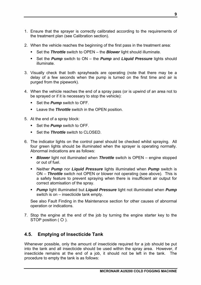
1. Ensure that the sprayer is correctly calibrated according to the requirements of
the treatment plan (see Calibration section). 2. When the vehicle reaches the beginning of the first pass in the treatment area: Set the Throttle switch to OPEN – the Blower light should illuminate. Set the Pump switch to ON – the Pump and Liquid Pressure lights should
illuminate. 3. Visually check that both sprayheads are operating (note that there may be a
delay of a few seconds when the pump is turned on the first time and air is purged from the pipework).
4. When the vehicle reaches the end of a spray pass (or is upwind of an area not to
be sprayed or if it is necessary to stop the vehicle): Set the Pump switch to OFF. Leave the Throttle switch in the OPEN position.
5. At the end of a spray block: Set the Pump switch to OFF. Set the Throttle switch to CLOSED.
6. The indicator lights on the control panel should be checked whilst spraying. All
four green lights should be illuminated when the sprayer is operating normally. Abnormal indications are as follows: Blower light not illuminated when Throttle switch is OPEN – engine stopped
or out of fuel. Neither Pump nor Liquid Pressure lights illuminated when Pump switch is
ON – Throttle switch not OPEN or blower not operating (see above). This is a safety feature to prevent spraying when there is insufficient air output for correct atomisation of the spray.
Pump light illuminated but Liquid Pressure light not illuminated when Pump switch is on – insecticide tank empty.
See also Fault Finding in the Maintenance section for other causes of abnormal operation or indications.
7. Stop the engine at the end of the job by turning the engine starter key to the
STOP position ( ). 4.5. Emptying of Insecticide Tank Whenever possible, only the amount of insecticide required for a job should be put into the tank and all insecticide should be used within the spray area. However, if insecticide remains at the end of a job, it should not be left in the tank. The procedure to empty the tank is as follows:
10
MICRONAIR AU9200 COLD FOGGING MACHINE
1. If not already in place, fit a length of 13 mm (1/2”) inside diameter hose over the
drain fitting (3). 2. Position a container of adequate capacity below the level of the bottom of the
insecticide tank and put the free end of the drain hose into the container. 3. Ensure that the isolation valve (2) is OPEN. 4. OPEN the drain valve (1) until all insecticide has been drained from the sprayer. 5. CLOSE the drain valve and remove the drain hose if required. 6. Store or dispose of the insecticide drained from the sprayer according to the
instructions on the label and statutory requirements. 5. HEALTH & SAFETY Legislation regarding the application of insecticides that are potentially harmful to individuals or the environment varies considerably between countries. Operators using insecticides and equipment must ensure they are working within the regulations applicable to their area. Irrespective of legislation, Micron Sprayers Limited advise the users of their equipment that all possible care must be taken to ensure the health and safety of the user and personnel in the vicinity of the spraying operation. The following recommendations are for guidance only and do not exclude any statutory requirement: 1. The application of each insecticide should follow the recommendations of the
manufacturer. Extreme care should be taken to prevent insecticide reaching the operator or any target where contamination could have an adverse effect.
2. Ensure that the equipment is correctly calibrated for the product being used. 3. Suitable clothing, gloves, eye protection and masks must be worn when mixing or
working with or near toxic products and operators must adhere to all relevant handling precautions and regulations.
4. Hearing protection must be worn whilst standing within 2m (6 feet) of the sprayer
when the engine is running. Hearing protection should not be worn by personnel in the vehicle cab.
5. The doors and windows of the vehicle cab should be kept closed whilst the
sprayer is operating. 6. The sprayer should never be operated whilst the vehicle is travelling downwind
(ie wind blowing from behind).
11
MICRONAIR AU9200 COLD FOGGING MACHINE
7. The entire spray system and all ancillary equipment must be thoroughly washed out after use or before maintenance.
8. All insecticide residues must be safely stored or disposed of. 9. All used insecticide containers must be safely disposed of in accordance with
local regulations and requirements. 10. First aid and washing facilities must always be available and personnel must be
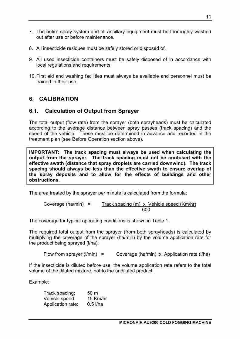
trained in their use. 6. CALIBRATION 6.1. Calculation of Output from Sprayer The total output (flow rate) from the sprayer (both sprayheads) must be calculated according to the average distance between spray passes (track spacing) and the speed of the vehicle. These must be determined in advance and recorded in the treatment plan (see Before Operation section above). IMPORTANT: The track spacing must always be used when calculating the output from the sprayer. The track spacing must not be confused with the effective swath (distance that spray droplets are carried downwind). The track spacing should always be less than the effective swath to ensure overlap of the spray deposits and to allow for the effects of buildings and other obstructions. The area treated by the sprayer per minute is calculated from the formula:
Coverage (ha/min) = Track spacing (m) x Vehicle speed (Km/hr) 600
The coverage for typical operating conditions is shown in Table 1. The required total output from the sprayer (from both sprayheads) is calculated by multiplying the coverage of the sprayer (ha/min) by the volume application rate for the product being sprayed (l/ha):
Flow from sprayer (l/min) = Coverage (ha/min) x Application rate (l/ha) If the insecticide is diluted before use, the volume application rate refers to the total volume of the diluted mixture, not to the undiluted product. Example:
Track spacing: 50 m Vehicle speed: 15 Km/hr Application rate: 0.5 l/ha
12
MICRONAIR AU9200 COLD FOGGING MACHINE
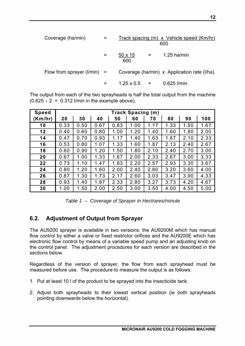
Coverage (ha/min) = Track spacing (m) x Vehicle speed (Km/hr) 600 = 50 x 15 = 1.25 ha/min 600
Flow from sprayer (l/min) = Coverage (ha/min) x Application rate (l/ha) = 1.25 x 0.5 = 0.625 l/min
The output from each of the two sprayheads is half the total output from the machine (0.625 ÷ 2 = 0.312 l/min in the example above).
Speed(Km/hr) 20 30 40 50 60 70 80 90 100
10 0.33 0.50 0.67 0.83 1.00 1.17 1.33 1.50 1.6712 0.40 0.60 0.80 1.00 1.20 1.40 1.60 1.80 2.0014 0.47 0.70 0.93 1.17 1.40 1.63 1.87 2.10 2.3316 0.53 0.80 1.07 1.33 1.60 1.87 2.13 2.40 2.6718 0.60 0.90 1.20 1.50 1.80 2.10 2.40 2.70 3.0020 0.67 1.00 1.33 1.67 2.00 2.33 2.67 3.00 3.3322 0.73 1.10 1.47 1.83 2.20 2.57 2.93 3.30 3.6724 0.80 1.20 1.60 2.00 2.40 2.80 3.20 3.60 4.0026 0.87 1.30 1.73 2.17 2.60 3.03 3.47 3.90 4.3328 0.93 1.40 1.87 2.33 2.80 3.27 3.73 4.20 4.6730 1.00 1.50 2.00 2.50 3.00 3.50 4.00 4.50 5.00
Track Spacing (m)
Table 1 – Coverage of Sprayer in Hectrares/minute 6.2. Adjustment of Output from Sprayer The AU9200 sprayer is available in two versions: the AU9200M which has manual flow control by either a valve or fixed restrictor orifices and the AU9200E which has electronic flow control by means of a variable speed pump and an adjusting knob on the control panel. The adjustment procedures for each version are described in the sections below. Regardless of the version of sprayer, the flow from each sprayhead must be measured before use. The procedure to measure the output is as follows: 1. Put at least 10 l of the product to be sprayed into the insecticide tank. 2. Adjust both sprayheads to their lowest vertical position (ie both sprayheads
pointing downwards below the horizontal).

13
MICRONAIR AU9200 COLD FOGGING MACHINE
3. Push a 200 mm length of 12 mm outside diameter plastic tube (Micronair part number EX6895 or equivalent) inside the inner tube of each sprayhead as shown in Fig. 4. Ensure that both these calibration tubes are pushed completely in until they touch the inside faces of the sprayheads and that they are a tight fit and will not come out during calibration.
4. Make the necessary initial adjustments to the flow control (see sections below). 5. Place or hold a bucket or other large container under each sprayhead. 6. Set the switches on the control box as follows: Master: ON Pump: ON Throttle: OPEN
IMPORTANT: The engine of the sprayer must NOT be run during calibration.
7. Press and hold the Calibrate switch on the box near the engine (1 in Fig. 3) until
a steady stream of insecticide comes from the calibration tube in each sprayhead.
8. Place a graduated jug or measuring cylinder under each calibration tube and
collect insecticide for a measured time (typically 1 or 2 minutes, depending upon the flow rate and the size of the measuring container).
9. Release the Calibrate switch.
Fig. 4 – Tube Fitted to Sprayhead for Calibration
14
MICRONAIR AU9200 COLD FOGGING MACHINE
10. Check the volumes of insecticide collected. The amounts in each container should not differ by more than about 10%. Put the insecticide from both heads into one graduated jug or measuring cylinder and measure the total volume collected. Divide this by the time for the measurement to obtain the total flow rate from the sprayer.
IMPORTANT: Wear gloves, protective clothing and eye protection when calibrating the sprayer. Return insecticide collected from the sprayheads to the main tank and wash all measuring containers etc after use.
Example: Volume from right-hand sprayhead: 0.305 l Volume from left-hand sprayhead: 0.320 l Time to collect measured volumes: 2 minutes
Total volume (l) = 0.305 + 0.320 l = 0.625 l
Flow rate (l/min) = Total volume (l) Time (min)
= 0.625 = 0.314 l/min 2
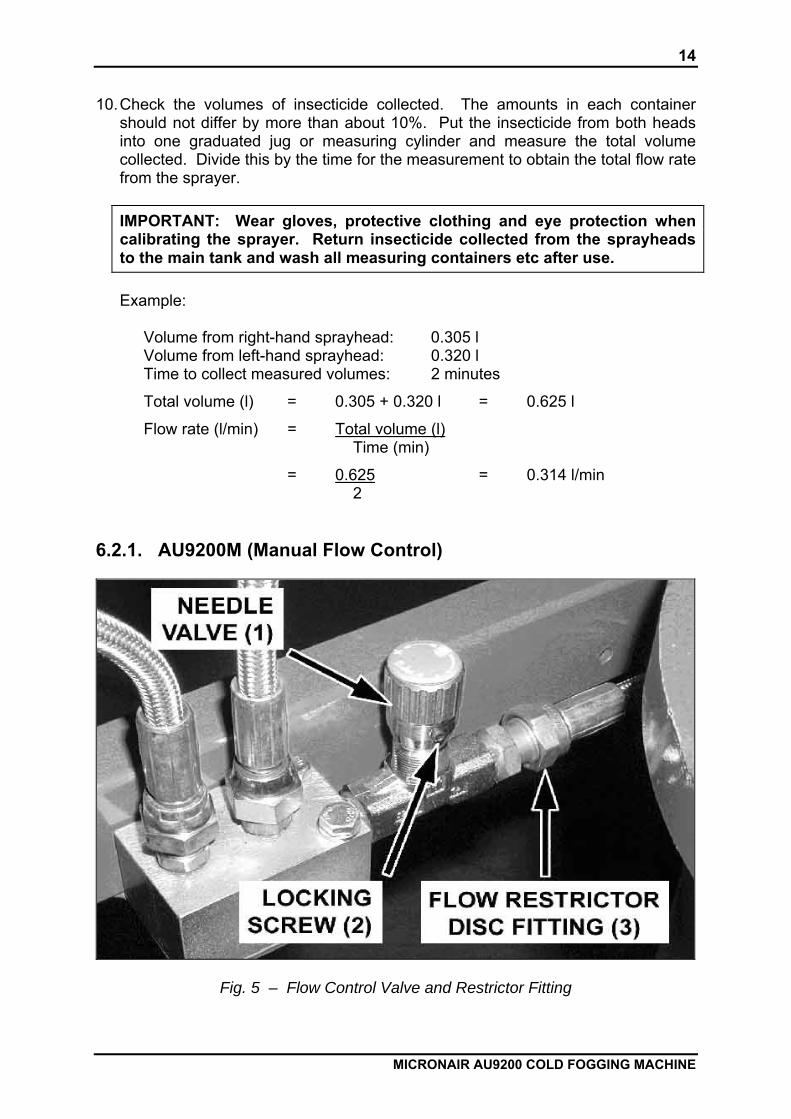
6.2.1. AU9200M (Manual Flow Control)
Fig. 5 – Flow Control Valve and Restrictor Fitting
15
MICRONAIR AU9200 COLD FOGGING MACHINE
The flow rate from the AU9200M can be controlled either by a variable needle valve or by interchangeable fixed restrictor orifice discs in the feed to the atomisers. If the needle valve is used, no orifice plate should be fitted. If an orifice plate is used, the needle valve must be set in the fully open position. Calibration procedures are given in the following sections. 6.2.1.1. Calibration with Adjustable Flow Valve 1. Ensure that there is no orifice disc fitted in the feed to the sprayheads (3 in Fig.
5). 2. Set the needle valve (1 in Fig. 5) to approximately mid-position. 3. Check the calibration of the sprayer as described in section 6.2 above. 4. If the flow rate is too high, decrease the opening of the valve by turning the
adjusting knob in a clockwise direction. If the rate is too low, increase the flow by turning the adjusting knob in an anti-clockwise direction.
5. Repeat steps (3) & (4) until the correct flow rate is obtained. 6. Lock the knob of the needle valve in position, using a 2 mm Allen (hexagon) key
(Micronair P/N CBP2524) to tighten the locking screw (2 in Fig. 5). 6.2.1.2. Calibration with Fixed Flow Restrictor 1. Refer to Table 2 below to determine the size of restrictor orifice disc that gives a
flow rate closest to the required rate. 2. Remove the hose fitting from the restrictor housing (3 in Fig. 5) and fit the
appropriate disc inside (ensure that any existing disc is removed first and that the non-return valve remains in position inside the housing).
3. Replace the hose fitting on the restrictor housing and tighten with a spanner. 4. Ensure that the needle valve is fully open. 5. Check the calibration of the sprayer as described in section 6.2 above. 6. If the flow rate is too high, replace the orifice disc with the next smaller size. If
the rate is too low, replace the disc with the next larger size. Repeat step (5).
16
MICRONAIR AU9200 COLD FOGGING MACHINE
Disc Number Flow from Sprayer (l/min)
20 0.20 24 0.30 30 0.40 39 0.65 49 0.80 59 0.90 80 1.00
Table 2 – Approximate Flow Rates Through Restrictor Orifice Discs
6.2.2. AU9200E (Electronic Flow Control) The Flow adjustment knob on the control box has graduations corresponding to approximate flow in l/minute. Actual flow rate will be affected by the physical properties of the insecticide, ambient temperature, battery voltage etc. The calibration of the sprayer should always be checked as follows: 1. Set the Flow adjustment knob on the control box to the required flow rate. 2. Check the calibration of the sprayer as described in section 6.2 above. 3. If the flow rate is too high or too low, move the Flow knob to a slightly lower or
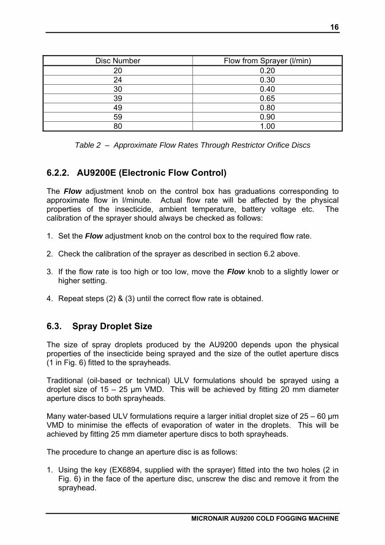
higher setting. 4. Repeat steps (2) & (3) until the correct flow rate is obtained. 6.3. Spray Droplet Size The size of spray droplets produced by the AU9200 depends upon the physical properties of the insecticide being sprayed and the size of the outlet aperture discs (1 in Fig. 6) fitted to the sprayheads. Traditional (oil-based or technical) ULV formulations should be sprayed using a droplet size of 15 – 25 μm VMD. This will be achieved by fitting 20 mm diameter aperture discs to both sprayheads. Many water-based ULV formulations require a larger initial droplet size of 25 – 60 μm VMD to minimise the effects of evaporation of water in the droplets. This will be achieved by fitting 25 mm diameter aperture discs to both sprayheads. The procedure to change an aperture disc is as follows: 1. Using the key (EX6894, supplied with the sprayer) fitted into the two holes (2 in
Fig. 6) in the face of the aperture disc, unscrew the disc and remove it from the sprayhead.
17
MICRONAIR AU9200 COLD FOGGING MACHINE
2. Reverse the removal procedure to fit the alternative disc. Note that aperture discs can be identified by the size (in mm) stamped onto the outer face.
Fig. 6 – Air Outlet Disc of Sprayhead 7. MAINTENANCE 7.1. General The AU9200 sprayer is constructed from durable, chemical resistant materials and will give long service if it is correctly used and maintained. In addition to the specific maintenance instructions in the sections below, the following procedures must be followed: 1. The insecticide tank must be emptied after use if the sprayer is not to be used
again within a period of 12 hours. See Operation section. 2. All external surfaces of the sprayer should be cleaned after use to remove any
chemical residues, dust etc. The machine should normally be cleaned with a cloth soaked with water and detergent. In the event of severe contamination with oil-based chemicals, a cloth soaked in kerosene or diesel can be used first. Do not use a high-pressure hose or steam cleaner as this could force water into electrical and other vulnerable components.
IMPORTANT: Wear gloves and eye protection when cleaning the sprayer and dispose of contaminated cleaning cloths and washing liquid safely.

18
MICRONAIR AU9200 COLD FOGGING MACHINE
3. The sprayer should be protected from rain and prolonged direct sunlight when not
in use, either by parking the vehicle under cover or by covering the machine with a protective sheet.
4. The fuel tank should be emptied if the sprayer is not to be used for more than one
month. This can be done by closing the fuel valve, removing the fuel hose from the valve and then opening the valve to drain the fuel into a suitable container. After emptying the fuel tank, the engine should be run to use up all fuel in the pipework and carburettor.
7.2. Engine Full maintenance instructions for the Honda GX620 engine are given in the Honda Engine Owner’s Manual supplied with each sprayer. Additional information, including spare parts lists, will be found on the Honda web site at www.honda-engines-eu.com. The following maintenance schedule is applicable to engines operating in a typical urban environment. Service intervals should be reduced as shown when operating in dusty conditions. Item
Action Normal service interval – carry out action at each calendar interval or number of operating hours, whichever comes first
Each use
First mth or 20 hrs
Every 3 mths or 50 hrs
Every 6 mths or 100 hrs
Every year or 300 hrs
Check level Engine oil Change [1] [1]
Engine oil filter Replace [2] Check Clean [3]
Air cleaner
Replace [4] Check/clean [5] Spark plug Replace
Running/idle speed
Check/adjust [6]
Valve clearance Check/adjust [7] Check Fuel filter Replace
Fuel line Check & replace if necessary
Every 2 years [8]
Table 3 – Engine Maintenance Schedule
19
MICRONAIR AU9200 COLD FOGGING MACHINE
Notes: [1] Recommended oil for engine: SAE 10W-30 multigrade (suitable for -15 ºC –
+40 ºC ambient temperature). Oil capacity 1.1 l without filter change, 1.4 l with filter change (approx).
[2] At the same time as each second oil change. Filter part number ##. [3] Reduce service interval to 1 month or 25 hours (or less if necessary) in dusty
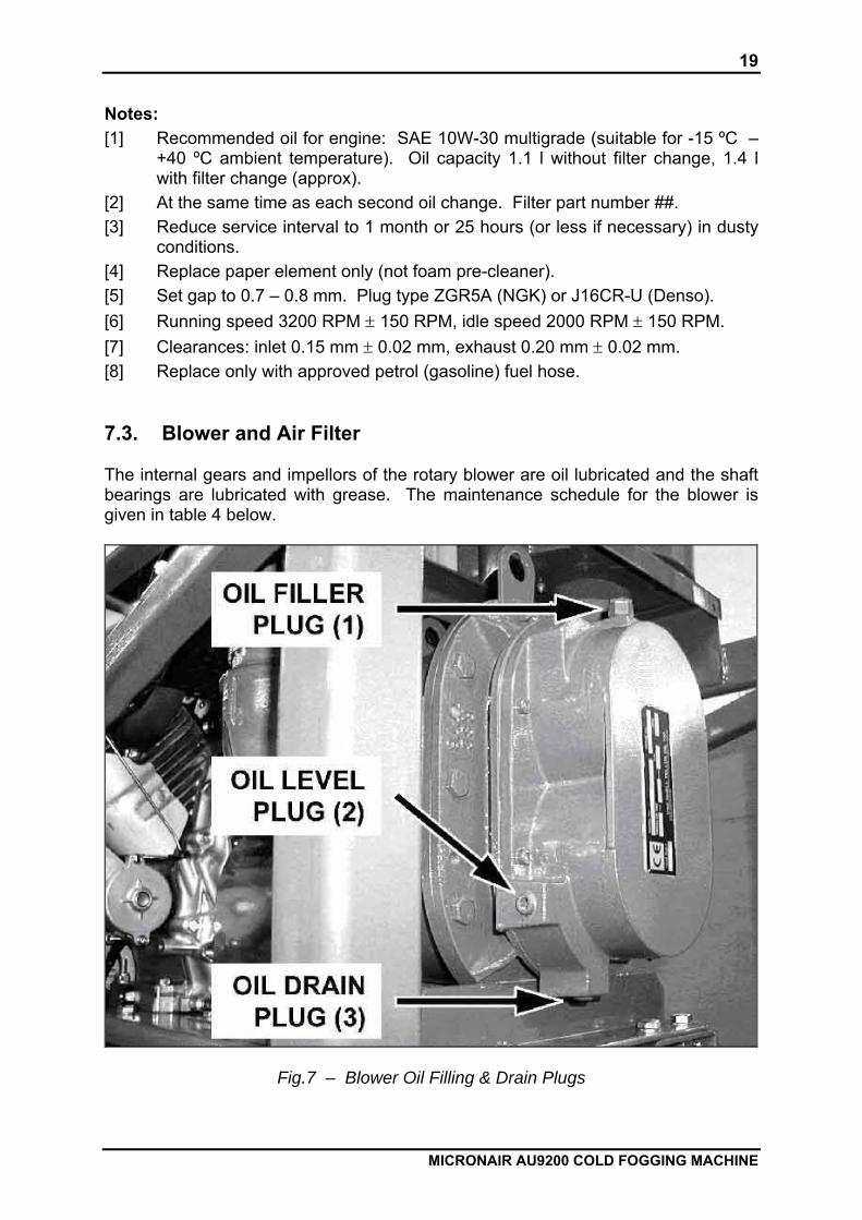
conditions. [4] Replace paper element only (not foam pre-cleaner). [5] Set gap to 0.7 – 0.8 mm. Plug type ZGR5A (NGK) or J16CR-U (Denso). [6] Running speed 3200 RPM ± 150 RPM, idle speed 2000 RPM ± 150 RPM. [7] Clearances: inlet 0.15 mm ± 0.02 mm, exhaust 0.20 mm ± 0.02 mm. [8] Replace only with approved petrol (gasoline) fuel hose. 7.3. Blower and Air Filter The internal gears and impellors of the rotary blower are oil lubricated and the shaft bearings are lubricated with grease. The maintenance schedule for the blower is given in table 4 below.
Fig.7 – Blower Oil Filling & Drain Plugs

20
MICRONAIR AU9200 COLD FOGGING MACHINE
The procedure to drain oil from the blower is as follows (numbers refer to Fig 7):
1. Run the engine and blower for 5 minutes to warm the oil and then stop the engine.
2. Remove the filler plug (1), then place a container under the drain plug (3) and remove the plug.
3. Allow all oil to drain from the blower and replace the drain plug (3). The procedure to add oil to the blower is as follows:
1. Remove the filler plug (1).
2. Place a container under the oil level plug (2) and remove the plug.
3. Slowly pour oil into the filler hole (1) until it begins to run out of the level hole (2).
4. Allow any surplus oil to run out of the level hole and replace the filler and level plugs.
To check the oil level, follow the above procedure and add a small quantity of oil. If the blower is full, this will immediately run out of the level hole. The blower is fitted with a foam air inlet filter. This must be removed and cleaned as shown in the schedule below. To remove the filter, unscrew the black retaining knob on the lid of the filter housing, remove the lid and pull out the filter. After removal from its housing, the filter should be cleaned by tapping it to remove any loose dust and then blowing it with compressed air, working from the outlet (lower) face. The filter should not be oiled after cleaning. Should the filter require replacement, use only a genuine Micronair spare part. Use of standard (non-reticulated) foam will cause an excessive pressure drop and could overload the blower and engine. Normal service interval – perform operation at
each calendar interval or number of operating hours, whichever comes first
Item
Action Each use First month or
20 hrs
Every 3 months or
50 hrs
Every year or 300 hrs
Check level Oil in blower Change [1]
Blower bearings Grease [2] Check Blower air inlet
filter Clean [3]
Table 4 – Blower and Air Filter Maintenance Schedule
21
MICRONAIR AU9200 COLD FOGGING MACHINE
Notes: [1] Use only mineral oil to ISO 3448, viscosity grade SAE 100. See Table 5 for
suitable types. If these are not available, a good quality SAE 100 grade automotive gearbox oil (not automatic transmission fluid) may be used. The oil capacity is approximately 370 ml.
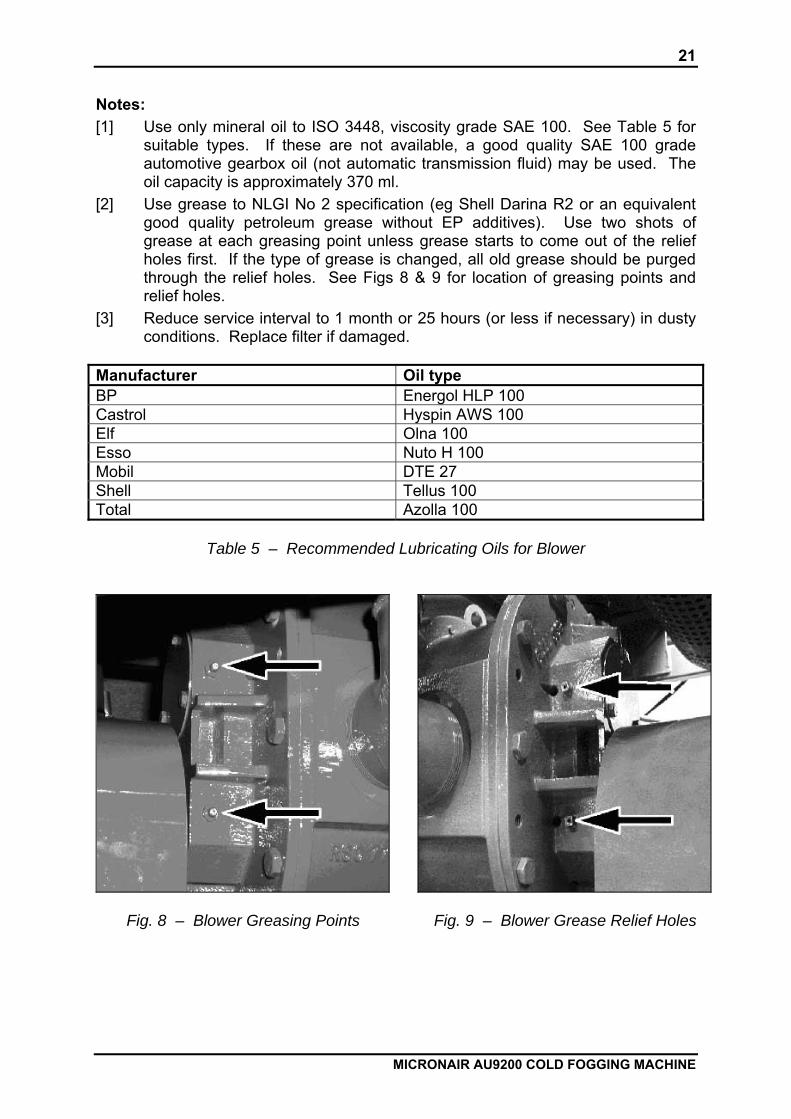
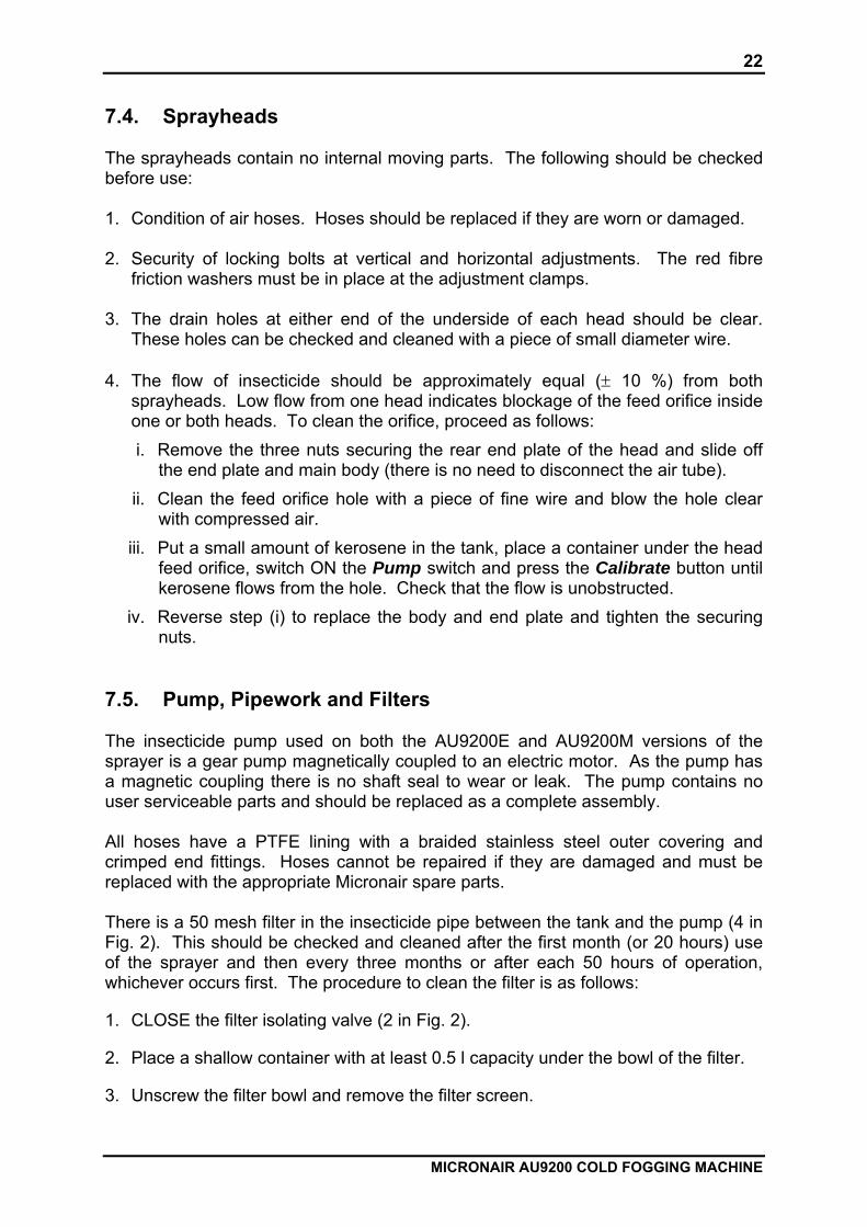
[2] Use grease to NLGI No 2 specification (eg Shell Darina R2 or an equivalent good quality petroleum grease without EP additives). Use two shots of grease at each greasing point unless grease starts to come out of the relief holes first. If the type of grease is changed, all old grease should be purged through the relief holes. See Figs 8 & 9 for location of greasing points and relief holes.
[3] Reduce service interval to 1 month or 25 hours (or less if necessary) in dusty conditions. Replace filter if damaged.
Manufacturer Oil type BP Energol HLP 100 Castrol Hyspin AWS 100 Elf Olna 100 Esso Nuto H 100 Mobil DTE 27 Shell Tellus 100 Total Azolla 100
Table 5 – Recommended Lubricating Oils for Blower
Fig. 8 – Blower Greasing Points
Fig. 9 – Blower Grease Relief Holesxxx
22
MICRONAIR AU9200 COLD FOGGING MACHINE
7.4. Sprayheads The sprayheads contain no internal moving parts. The following should be checked before use: 1. Condition of air hoses. Hoses should be replaced if they are worn or damaged. 2. Security of locking bolts at vertical and horizontal adjustments. The red fibre
friction washers must be in place at the adjustment clamps. 3. The drain holes at either end of the underside of each head should be clear.
These holes can be checked and cleaned with a piece of small diameter wire. 4. The flow of insecticide should be approximately equal (± 10 %) from both
sprayheads. Low flow from one head indicates blockage of the feed orifice inside one or both heads. To clean the orifice, proceed as follows: i. Remove the three nuts securing the rear end plate of the head and slide off
the end plate and main body (there is no need to disconnect the air tube). ii. Clean the feed orifice hole with a piece of fine wire and blow the hole clear
with compressed air. iii. Put a small amount of kerosene in the tank, place a container under the head
feed orifice, switch ON the Pump switch and press the Calibrate button until kerosene flows from the hole. Check that the flow is unobstructed.
iv. Reverse step (i) to replace the body and end plate and tighten the securing nuts.
7.5. Pump, Pipework and Filters The insecticide pump used on both the AU9200E and AU9200M versions of the sprayer is a gear pump magnetically coupled to an electric motor. As the pump has a magnetic coupling there is no shaft seal to wear or leak. The pump contains no user serviceable parts and should be replaced as a complete assembly. All hoses have a PTFE lining with a braided stainless steel outer covering and crimped end fittings. Hoses cannot be repaired if they are damaged and must be replaced with the appropriate Micronair spare parts. There is a 50 mesh filter in the insecticide pipe between the tank and the pump (4 in Fig. 2). This should be checked and cleaned after the first month (or 20 hours) use of the sprayer and then every three months or after each 50 hours of operation, whichever occurs first. The procedure to clean the filter is as follows:
1. CLOSE the filter isolating valve (2 in Fig. 2).
2. Place a shallow container with at least 0.5 l capacity under the bowl of the filter.
3. Unscrew the filter bowl and remove the filter screen.
23
MICRONAIR AU9200 COLD FOGGING MACHINE
4. Clean the filter screen and inside the inside of the filter bowl
5. Fit the screen inside the bowl and screw them back onto the filter body. Do not over-tighten the thread.
6. OPEN the filter isolating valve. IMPORTANT: Wear gloves and eye protection when working on the pump, filter or pipework. Re-use any clean insecticide drained from the system and dispose of any contaminated residues, cleaning cloths etc safely.
24
MICRONAIR AU9200 COLD FOGGING MACHINE
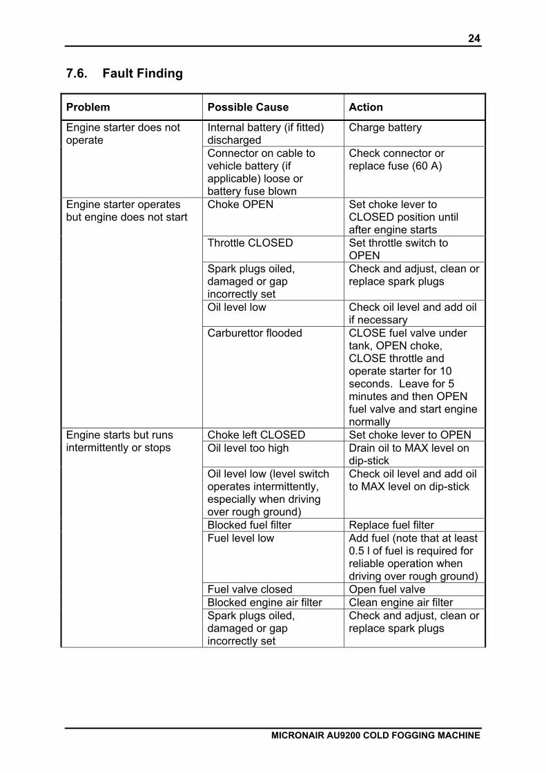
7.6. Fault Finding
Problem Possible Cause Action
Internal battery (if fitted) discharged
Charge battery
Engine starter does not operate
Connector on cable to vehicle battery (if applicable) loose or battery fuse blown
Check connector or replace fuse (60 A)
Choke OPEN Set choke lever to CLOSED position until after engine starts
Throttle CLOSED Set throttle switch to OPEN
Spark plugs oiled, damaged or gap incorrectly set
Check and adjust, clean or replace spark plugs
Oil level low Check oil level and add oil if necessary
Engine starter operates but engine does not start
Carburettor flooded CLOSE fuel valve under tank, OPEN choke, CLOSE throttle and operate starter for 10 seconds. Leave for 5 minutes and then OPEN fuel valve and start engine normally
Choke left CLOSED Set choke lever to OPEN Oil level too high Drain oil to MAX level on
dip-stick Oil level low (level switch operates intermittently, especially when driving over rough ground)
Check oil level and add oil to MAX level on dip-stick
Blocked fuel filter Replace fuel filter Fuel level low Add fuel (note that at least
0.5 l of fuel is required for reliable operation when driving over rough ground)
Fuel valve closed Open fuel valve Blocked engine air filter Clean engine air filter
Engine starts but runs intermittently or stops
Spark plugs oiled, damaged or gap incorrectly set
Check and adjust, clean or replace spark plugs

25
MICRONAIR AU9200 COLD FOGGING MACHINE
Engine does not reach normal speed with throttle OPEN or blower air inlet filter condition indicator shows RED
Blower air inlet filter blocked
Clean foam filter inside inlet filter casing
Connector of control panel cable not securely fitted at sprayer
Fit connector and lock in position
Battery fuse blown (vehicle battery powered systems only)
Replace battery fuse (60 A)
Master indicator not illuminated when master switch ON
Control system fuse blown Replace control system fuse at junction box on sprayer (7 A)
Filter isolation valve CLOSED
OPEN valve
Main spray liquid filter blocked
Clean main spray liquid filter
Check valve or check valve filter blocked
Remove check valve and filter, clean and replace
Restrictor valve or orifice blocked (manual flow control version only)
Dismantle and clean valve or restrictor orifice
Pump motor not operating Check voltage at pump leads. If voltage is present repair or replace pump, if not investigate electrical system
No output from either sprayhead with pump ON (pump indicator ON)
Pump motor operating, but no flow from pump (magnetic pump coupling slipping)
Dismantle pump and check for internal blockage etc
Ensure that throttle switch is OPEN
Pump indicator not illuminated when pump switch ON
Blower switch not operating (pump only operates when there is air flow from blower)
Check operation of air flow switch and adjust or replace if necessary
No or reduced output from one sprayhead
Sprayhead feed restrictor blocked
Remove and clean feed restrictor (check both sprayheads)
Long delay between switching pump ON and output from sprayheads
Check valve stuck open Remove check valve and clean
Battery not charging (internal battery version only)
Fuse in engine control box blown
Replace fuse (see Honda Engine Owner’s Manual)
26
MICRONAIR AU9200 COLD FOGGING MACHINE
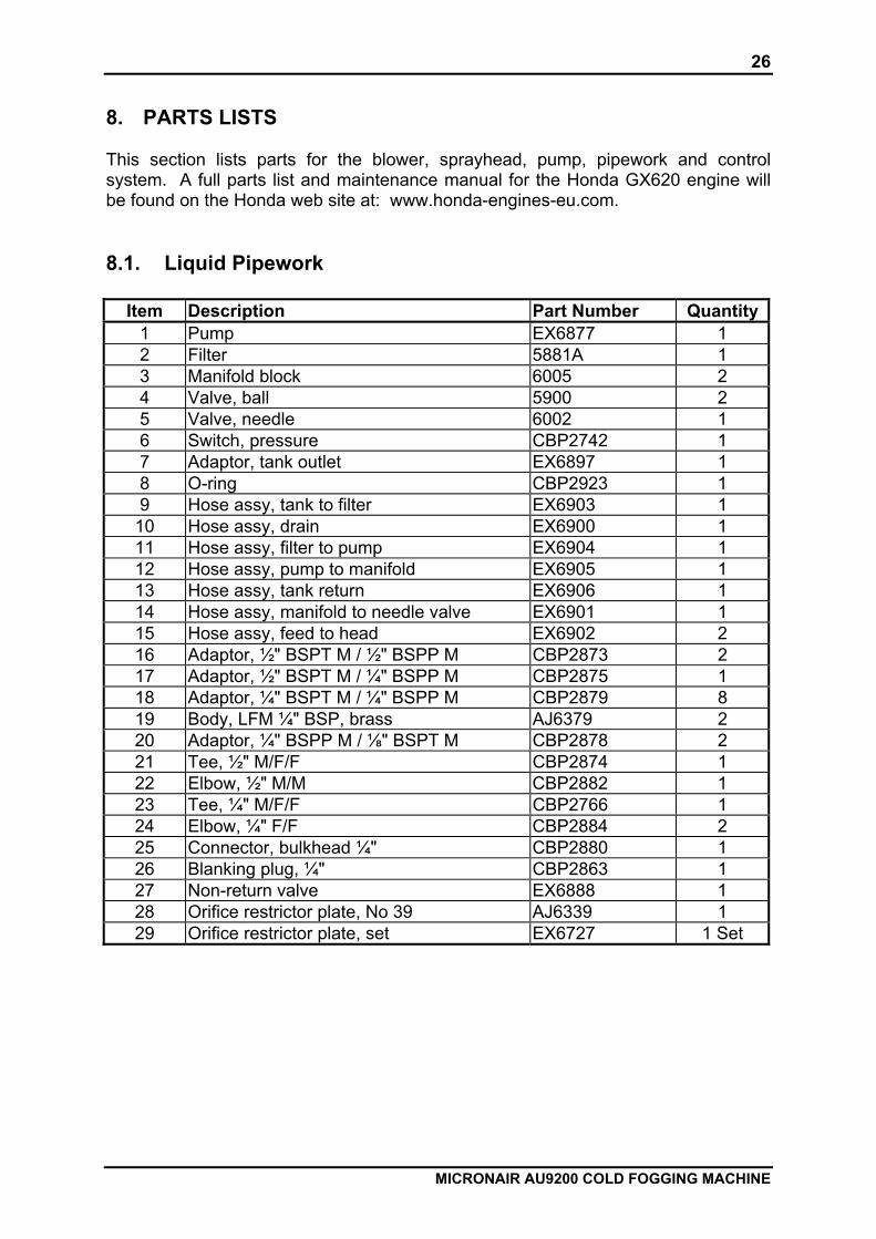
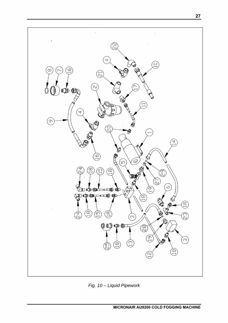
8. PARTS LISTS This section lists parts for the blower, sprayhead, pump, pipework and control system. A full parts list and maintenance manual for the Honda GX620 engine will be found on the Honda web site at: www.honda-engines-eu.com. 8.1. Liquid Pipework
Item Description Part Number Quantity1 Pump EX6877 1 2 Filter 5881A 1 3 Manifold block 6005 2 4 Valve, ball 5900 2 5 Valve, needle 6002 1 6 Switch, pressure CBP2742 1 7 Adaptor, tank outlet EX6897 1 8 O-ring CBP2923 1 9 Hose assy, tank to filter EX6903 1
10 Hose assy, drain EX6900 1 11 Hose assy, filter to pump EX6904 1 12 Hose assy, pump to manifold EX6905 1 13 Hose assy, tank return EX6906 1 14 Hose assy, manifold to needle valve EX6901 1 15 Hose assy, feed to head EX6902 2 16 Adaptor, ½" BSPT M / ½" BSPP M CBP2873 2 17 Adaptor, ½" BSPT M / ¼" BSPP M CBP2875 1 18 Adaptor, ¼" BSPT M / ¼" BSPP M CBP2879 8 19 Body, LFM ¼" BSP, brass AJ6379 2 20 Adaptor, ¼" BSPP M / ⅛" BSPT M CBP2878 2 21 Tee, ½" M/F/F CBP2874 1 22 Elbow, ½" M/M CBP2882 1 23 Tee, ¼" M/F/F CBP2766 1 24 Elbow, ¼" F/F CBP2884 2 25 Connector, bulkhead ¼" CBP2880 1 26 Blanking plug, ¼" CBP2863 1 27 Non-return valve EX6888 1 28 Orifice restrictor plate, No 39 AJ6339 1 29 Orifice restrictor plate, set EX6727 1 Set
27
MICRONAIR AU9200 COLD FOGGING MACHINE
Fig. 10 – Liquid Pipework
28
MICRONAIR AU9200 COLD FOGGING MACHINE
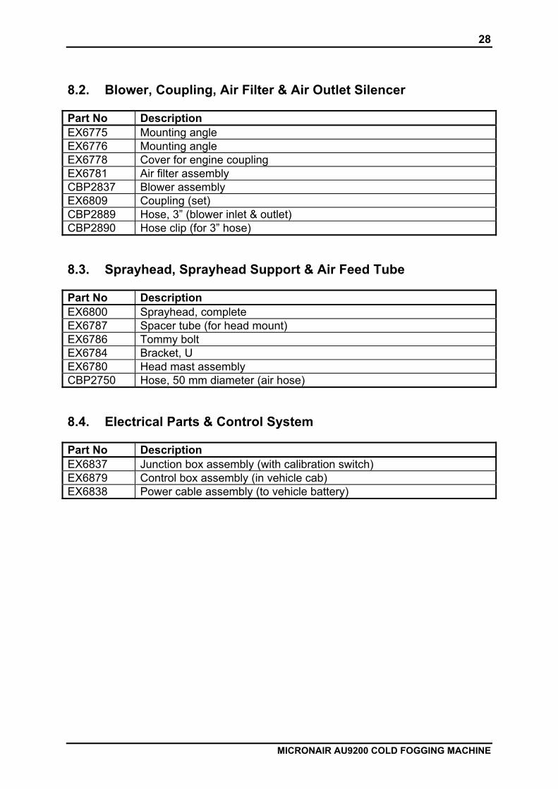
8.2. Blower, Coupling, Air Filter & Air Outlet Silencer Part No Description EX6775 Mounting angle EX6776 Mounting angle EX6778 Cover for engine coupling EX6781 Air filter assembly CBP2837 Blower assembly EX6809 Coupling (set) CBP2889 Hose, 3” (blower inlet & outlet) CBP2890 Hose clip (for 3” hose) 8.3. Sprayhead, Sprayhead Support & Air Feed Tube Part No Description EX6800 Sprayhead, complete EX6787 Spacer tube (for head mount) EX6786 Tommy bolt EX6784 Bracket, U EX6780 Head mast assembly CBP2750 Hose, 50 mm diameter (air hose) 8.4. Electrical Parts & Control System Part No Description EX6837 Junction box assembly (with calibration switch) EX6879 Control box assembly (in vehicle cab) EX6838 Power cable assembly (to vehicle battery)
29
MICRONAIR AU9200 COLD FOGGING MACHINE
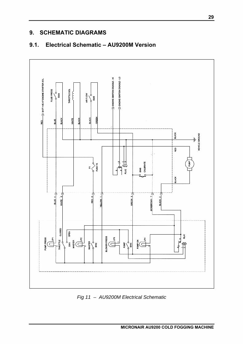
9. SCHEMATIC DIAGRAMS 9.1. Electrical Schematic – AU9200M Version
Fig 11 – AU9200M Electrical Schematic

30
MICRONAIR AU9200 COLD FOGGING MACHINE
10. WARRANTY Micron Sprayers Limited give a one year warranty covering all parts of the sprayer except the engine. The warranty period commences upon the delivery of the sprayer to the customer. The warranty is subject to the following conditions:
1. The sprayer must have been correctly installed on the vehicle and operated in accordance with the instructions in this handbook.
2. The sprayer must have been maintained in accordance with the maintenance schedules in this handbook.
3. Only genuine Micronair spare parts should have been fitted and no components should have been subject to unauthorised repair.
4. The sprayer must have been emptied and cleaned after use and must have been kept under cover and not exposed to extreme weather conditions when not in use.
Micron Sprayers undertake to replace or repair (at its sole discretion) any components that fail as a consequence of faulty materials or workmanship. This warranty is limited to the repair or replacement of components only. Micron Sprayers Limited are not responsible for any labour costs associated with the replacement of faulty components. The engine (but not the fuel tank, blower or blower coupling) is covered directly by Honda’s worldwide warranty. This is described in the warranty leaflet supplied with the engine. The local Honda service centre should be contacted direct in the event of a warranty claim relating to the engine. The engine and sprayer serial numbers must be quoted when contacting the service centre.
31
MICRONAIR AU9200 COLD FOGGING MACHINE
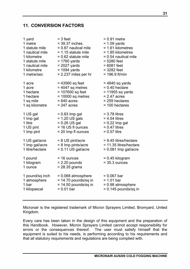
11. CONVERSION FACTORS 1 yard = 3 feet = 0.91 metre 1 metre = 39.37 inches = 1.09 yards 1 statute mile = 0.87 nautical mile = 1.61 kilometres 1 nautical mile = 1.15 statute mile = 1.85 kilometres 1 kilometre = 0.62 statute mile = 0.54 nautical mile 1 statute mile = 1760 yards = 5280 feet 1 nautical mile = 2027 yards = 6081 feet 1 kilometre = 1094 yards = 3282 feet 1 metre/sec = 2.237 miles per hr = 196.9 ft/min 1 acre = 43560 sq feet = 4840 sq yards 1 acre = 4047 sq metres = 0.40 hectare 1 hectare = 107600 sq feet = 11955 sq yards 1 hectare = 10000 sq metres = 2.47 acres 1 sq mile = 640 acres = 259 hectares 1 sq kilometre = 247 acres = 100 hectares 1 US gal = 0.83 Imp gal = 3.78 litres 1 Imp gal = 1.20 US gals = 4.54 litres 1 litre = 0.26 US gal = 0.22 Imp gal 1 US pint = 16 US fl ounces = 0.47 litres 1 Imp pint = 20 Imp fl ounces = 0.57 litre 1 US gal/acre = 8 US pint/acre = 9.45 litres/hectare 1 Imp gal/acre = 8 Imp pints/acre = 11.35 litres/hectare 1 litre/hectare = 0.11 US gal/acre = 0.081 Imp gal/acre 1 pound = 16 ounces = 0.45 kilogram 1 kilogram = 2.20 pounds = 35.3 ounces 1 ounce = 28.35 grams 1 pound/sq inch = 0.068 atmosphere = 0.067 bar 1 atmosphere = 14.70 pounds/sq in = 1.01 bar 1 bar = 14.50 pounds/sq in = 0.98 atmosphere 1 kilopascal = 0.01 bar = 0.145 pounds/sq in Micronair is the registered trademark of Micron Sprayers Limited, Bromyard, United Kingdom. Every care has been taken in the design of this equipment and the preparation of this Handbook. However, Micron Sprayers Limited cannot accept responsibility for errors or the consequences thereof. The user must satisfy himself that the equipment is suited to his needs, is performing according to his requirements and that all statutory requirements and regulations are being complied with.