Embed Size (px)
Citation preview
:
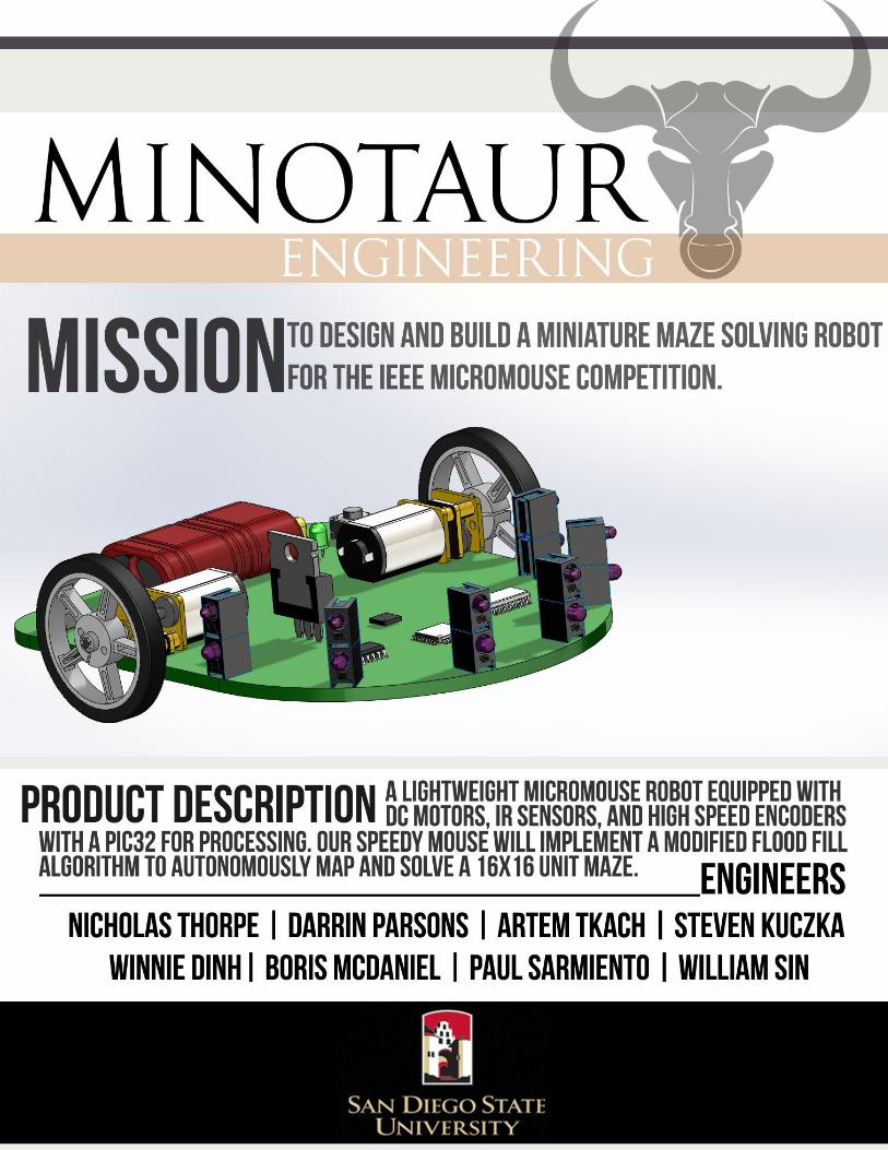
Micromouse is an engineering competition that involves building a miniature maze solving robot.
Minotaur Engineering plans to build a micromouse robot and compete against the other SDSU
micromouse senior design teams at the end of the semester. Our overall goal is to build the fastest
micromouse ever designed by SDSU students. We also plan on competing in the annual IEEE
Micromouse competition held at UCSD.
In our design speed is everything. In order to realize a fast moving maze solving robot Minotaur
Engineering is going to make our design as lightweight as possible and propel our mouse using high
speed dc motors. We will be using a PIC32MX340F512H as our microprocessor that will control all
peripheral equipment.
To make this mouse function properly and complete the desired task we will be incorporating feedback
from high speed motor encoders, infrared light detectors, and a gyro during maze operations.
The infrared light detectors will be sensing the distance to the walls of the maze which will be used as
feedback to the microprocessor to avoid collisions with the walls while moving through the maze. The
motor speeds will be monitored and regulated by the use of the motor encoders. The Gyro will help the
microprocessor figure its relative heading in the 16x16 unit square maze as it searches for the path to
the center.
We will implement a flood fill algorithm into the microprocessor to record the different paths to the
center of the maze. Through testing we will learn how to fine tune our algorithm and implement a
decision making process for the mouse to take when it encounters a corner or an intersection.
While competing we will have ten minutes for our mouse to get the best time to the center of the maze.
To accomplish this we are going to have three different modes of operation coded in our
microprocessor.
1. The mouse will maneuver throughout the maze and record as many paths to the center of the
maze in a specified amount of time and calculate the fastest path to the center of the maze.
2. In this “Fast Run” mode the mouse will take the fastest route to the center of the maze.
3. User input mode will facilitate testing and prototyping the various software functions that will
control the operation of the robot.
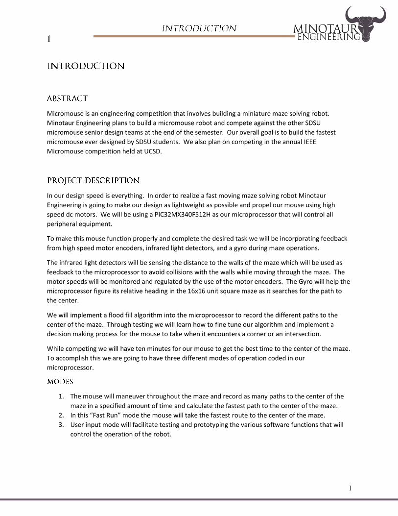
M
IR ReceiverPhototransistor
X3
IR EmitterInfared LED
X3
EncoderOptical
X2
Motor DriverTB6612FNG
GyroL3GD20H
M
MCUPIC32MX340F512H
Battery Voltage
Detection Unit
PowerSupply7.4V
Xbee
On/Off Switch
User ButtonsX3
LED StatusArray
UART UserInterface
3.3V LinearVoltage
Regulator
Analog Input
Serial Comm
Serial(I2C/SPI)
Digital Input
Digital Output(Direction)
PWM Output
Digital Output
Analog Input
Digital Input
Digital Output
MCU Power
Battery Voltage
3.3V
3.3V
3.3V
3.3V
3.3V3.3V
VBattExt. PC
ADCX2
Analog
Comparator
Analog Input
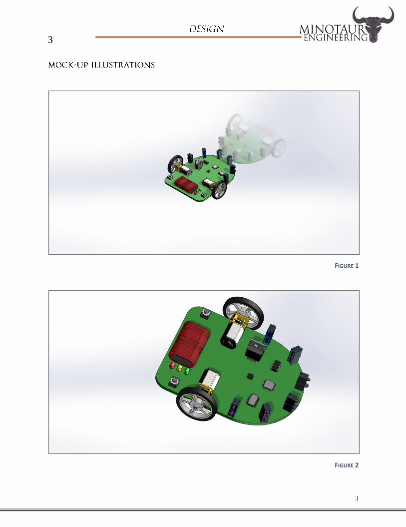
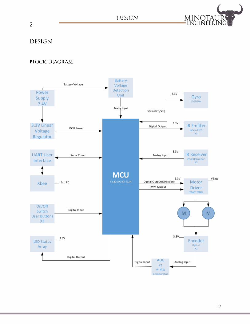
FIGURE 1
FIGURE 2
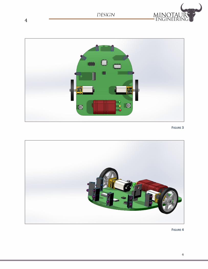
FIGURE 3
FIGURE 4
1. The Robot should be fully autonomous and able to solve an official IEEE Region 6 Southwest
certified maze with multiple paths to the destination.
2. The Robot must be able to solve the maze within the allocated 10 minute access time.
3. The Robot must calculate the fastest path out of a multiple paths to the center of the maze.
4. The Robot will be able to return to initial starting point after completion of mapping phase.
5. The Robot will be able to avoid collision with the 16x16 cm maze walls.
6. The Robot will have a mapping phase speed of 0.2 m/s and a fastest time attempt speed up to
1.0 m/s.
The testing results of the micromouse robot shall verify how reliably the robot is able to solve a 16x16
unit maze and find the fastest way to the center of the maze in 10 minutes.
Every hardware component of the micromouse will be tested individually. We will make sure that each
component functions properly and provides the necessary functionality.
To test motors we will connect them to a 7.4V power supply and measure the no load RPM and current.
Then we will measure the stall current to verify the max current drawn from the motors.
IR LED’s will be tested by iteration. We will start with the recommended specifications from the data
sheet then we will fine tune our circuit for our design needs.
Phototransistors will also be designed according to the manufactures data sheet and fine-tuned to meet
our specific design constraints.
We will assemble modules for the robot. Every module will be verified and tested individually as well.
After all requirements will be met the data will be logged and saved for the future references.
We will use a software simulator to test flood fill and solving algorithms.
The robot shall successfully solve and navigate through the maze.
After we make sure that maze solving functions work properly we will proceed to testing of the
functions with microcontroller.
Test motor driver function (start, stop, speed up, slow down, go straight, turn left, turn right, 90 and 180
degrees turns)
Test IR sensors controlling function
Test interrupts for motor driver

After installing hardware and integrating software we will start testing the micromouse.
The purpose of this test method is to evaluate the micromouse robot’s ability to sustain maneuvering
speed, navigate in the maze and solve the maze without hitting any walls within the 10 minutes time
frame.
There will be two main phases of testing.
:
1. Import the motor controlling software onto the uC32 microcontroller and make necessary
adjustments to the motor functions in order to process the data from the microcontroller’s
input/output ports.
2. Run the robot and make sure it can perform basic functions like drive straight and make turns.
Feedback from IR sensors will not be used at this stage of testing.
3. Run the robot and make sure it speeds up and slows down when required.
1. Import the navigation and solving software onto the uC32 microcontroller and make necessary
adjustments to the software functions in order to process the data from the microcontroller’s
input/output ports.
2. Run the robot and make sure it can navigate inside the maze without hitting any walls.
3. Test reset mode if robot hits a wall.
4. Run the robot and make sure it can navigate and map the maze without hitting ant walls.
5. Test the mapping mode where micromouse discovers and maps the maze.
6. Test the “fast run” mode where micromouse should get to the center of the maze in the fastest
time without hitting any walls.
1. Robot will be able to accelerate and decelerate smoothly within the range of 0 to 1.0 m/s
through the use of PWM signals.
2. Robot will be able to process and utilize sensor data to travel in the center path at a stable and
linear fashion.
3. Mapping algorithm will allow the robot to find multiple paths to the center without entering
infinite loops.
4. Speed run algorithm will be able to select the route that would result in the fastest time out of
all identified routes.
5. All mapping and speed runs will be completed within 10 minutes.
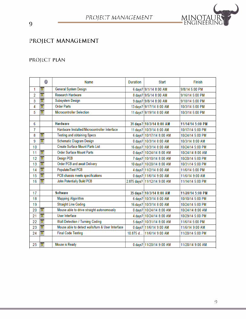
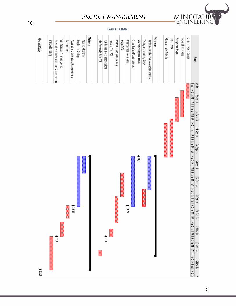
GANTT CHART
Hardware installed and able to interface with microcontroller.
Able to log and process IR sensor and encoder data via microcontroller.
Mouse able to navigate in a straight line autonomously.
Mouse able to navigate accurately without wall collision and able to interface with user
pushbuttons.
PCB chassis meets specifications.
Mouse will be able to find its way from a predetermined starting point to the central area
of the maze unaid
Motors/Motor Controllers
Encoders
Wheels
IR Sensors
PIC32
Gyro
Batteries PCB
Chassis
Reference Material
Miscellaneous
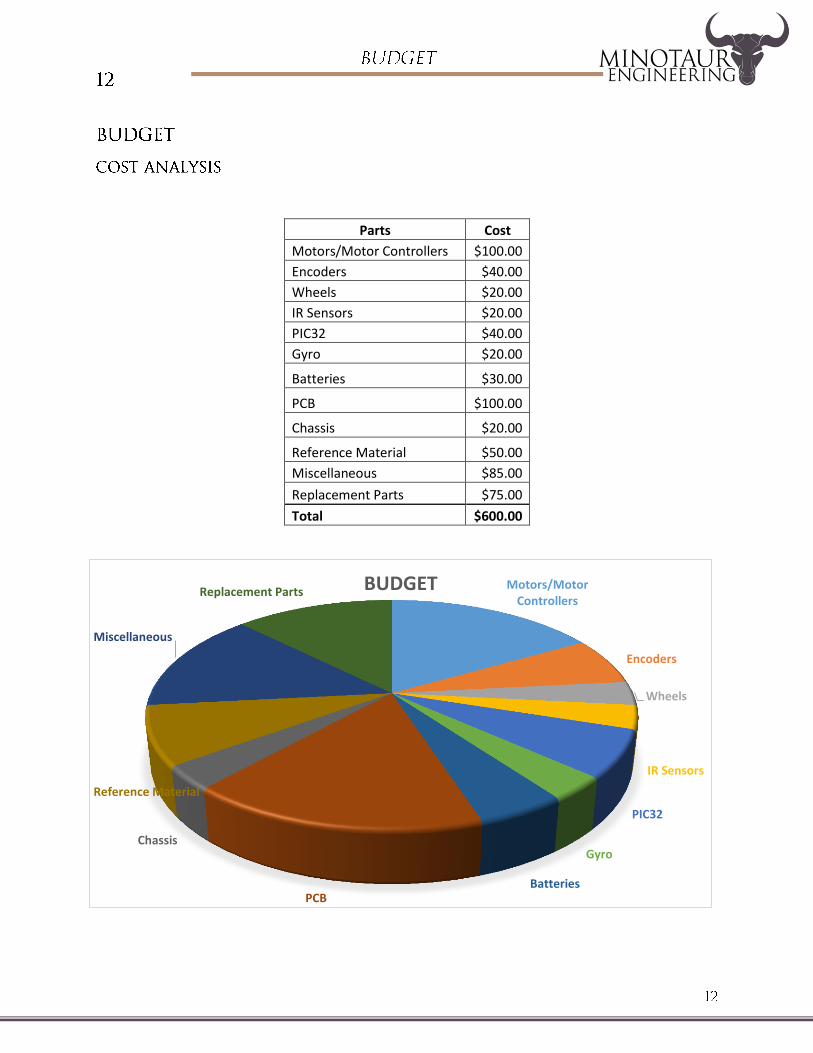
Replacement Parts BUDGET
Parts Cost
Motors/Motor Controllers $100.00
Encoders $40.00
Wheels $20.00
IR Sensors $20.00
PIC32 $40.00
Gyro $20.00
Batteries $30.00
PCB $100.00
Chassis $20.00
Reference Material $50.00
Miscellaneous $85.00
Replacement Parts $75.00
Total $600.00