Embed Size (px)
Citation preview
1
National Aeronautics and Space Administration
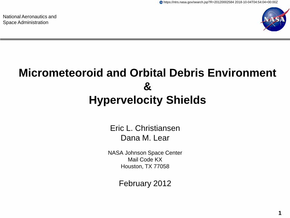
Micrometeoroid and Orbital Debris Environment &
Hypervelocity Shields
Eric L. Christiansen Dana M. Lear
NASA Johnson Space Center
Mail Code KX Houston, TX 77058
February 2012
https://ntrs.nasa.gov/search.jsp?R=20120002584 2018-10-04T04:54:04+00:00Z
2
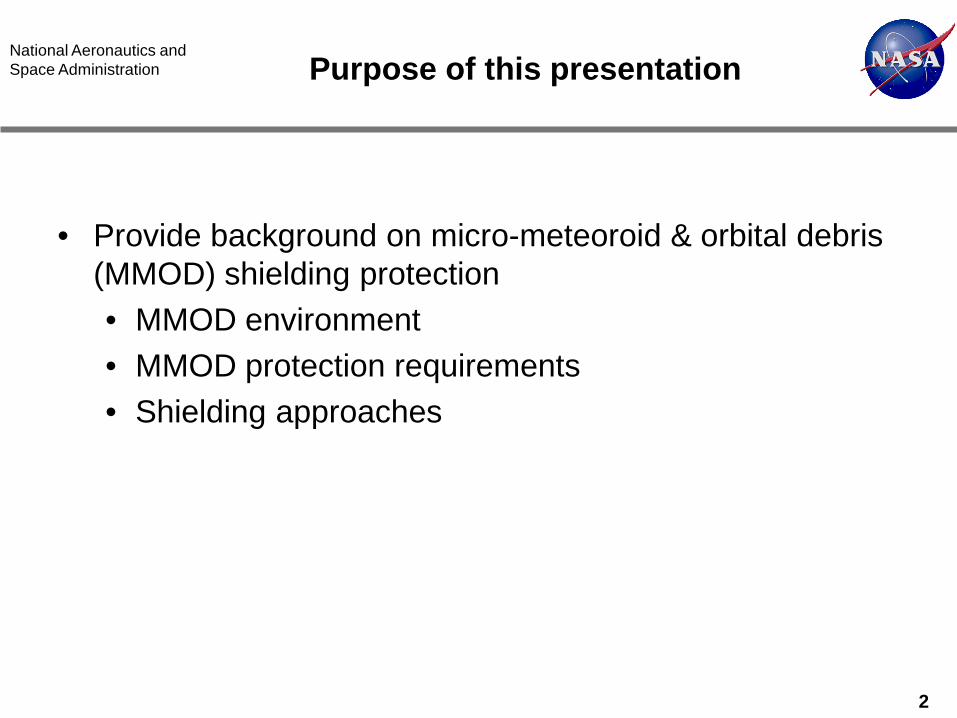
National Aeronautics and Space Administration Purpose of this presentation
• Provide background on micro-meteoroid & orbital debris (MMOD) shielding protection • MMOD environment • MMOD protection requirements • Shielding approaches
3
National Aeronautics and Space Administration MMOD Environment Models
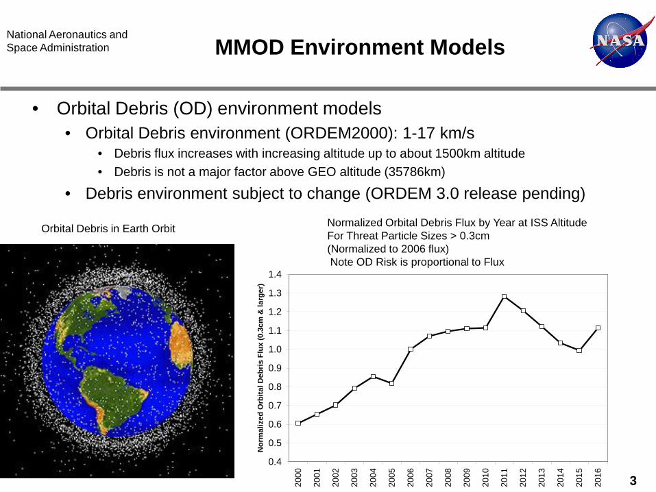
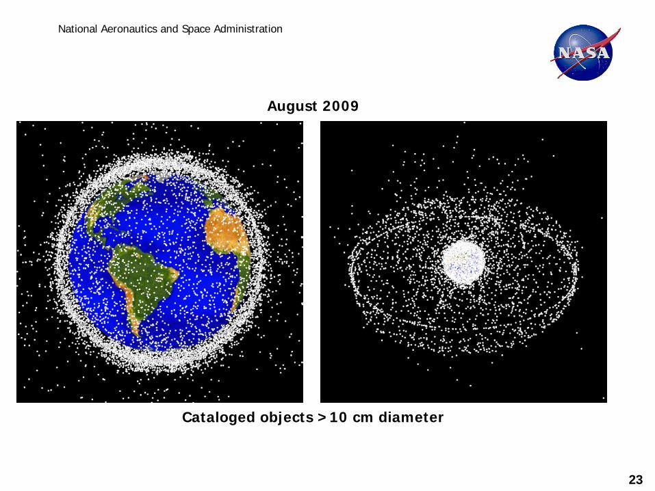
• Orbital Debris (OD) environment models • Orbital Debris environment (ORDEM2000): 1-17 km/s
• Debris flux increases with increasing altitude up to about 1500km altitude • Debris is not a major factor above GEO altitude (35786km)
• Debris environment subject to change (ORDEM 3.0 release pending)
Orbital Debris in Earth Orbit
0.4
0.5
0.6
0.7
0.8
0.9
1.0
1.1
1.2
1.3
1.4
2000
2001
2002
2003
2004
2005
2006
2007
2008
2009
2010
2011
2012
2013
2014
2015
2016
Nor
mal
ized
Orb
ital D
ebris
Flu
x (0
.3cm
& la
rger
)
Normalized Orbital Debris Flux by Year at ISS Altitude For Threat Particle Sizes > 0.3cm (Normalized to 2006 flux) Note OD Risk is proportional to Flux
4
National Aeronautics and Space Administration MMOD Environment Models (cont.)
• Meteoroid model (MEM) provided by MSFC • http://www.nasa.gov/offices/meo/home/index.html • Meteoroid environment (MEM): 11-72 km/s
• Average 22-23 km/s
• MM environment model is subject to change (new release of MEM is pending)
• Orbital Debris is the predominate threat in low Earth orbit • For ISS, debris represents approximately 2/3rds of the MMOD risk • For missions to the Moon, L1, or elsewhere, OD risk will need to be
assessed for time period spacecraft resides in LEO • Meteoroid risk is influenced by Earth focusing (gravitational) factor
and Earth shadowing while in Earth orbit • Meteoroid risk far from Earth is typically less compared to meteoroid risk
in LEO
5
National Aeronautics and Space Administration MMOD Damage to spacecraft
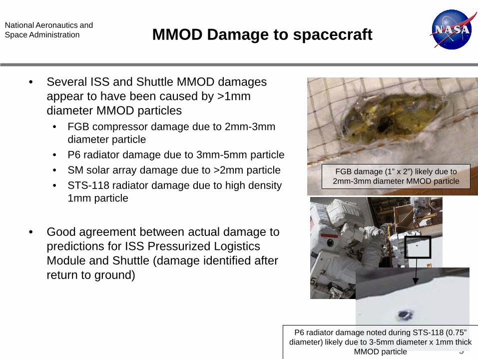
• Several ISS and Shuttle MMOD damages appear to have been caused by >1mm diameter MMOD particles
• FGB compressor damage due to 2mm-3mm diameter particle
• P6 radiator damage due to 3mm-5mm particle • SM solar array damage due to >2mm particle • STS-118 radiator damage due to high density
1mm particle
• Good agreement between actual damage to predictions for ISS Pressurized Logistics Module and Shuttle (damage identified after return to ground)
FGB damage (1” x 2”) likely due to 2mm-3mm diameter MMOD particle
P6 radiator damage noted during STS-118 (0.75” diameter) likely due to 3-5mm diameter x 1mm thick
MMOD particle
6
National Aeronautics and Space Administration
MMOD Shielding
7
National Aeronautics and Space Administration MMOD Protection Requirements
• MMOD risk is a function of vehicle size, mission duration (time exposed to MMOD), failure criteria, shielding, flight trajectory
• MMOD requirements are key aspect of providing adequate MMOD protection, crew safety and vehicle survivability
• Typically MMOD protection requirements expressed in terms of
maximum allowable failure risk over a time period, or a reliability level (probability of no failure) • For instance, Orion Lunar sortie (24 day mission) maximum allowable
MMOD loss-of-crew (LOC) risk is 1 in 1000 (0.1% risk), and Lunar outpost (210 day mission) maximum allowable MMOD risk is 1 in 500 (0.2% risk)
• Note, that over many missions, the cumulative MMOD risk increases with the total duration of all missions
8
National Aeronautics and Space Administration Hypervelocity impact effects
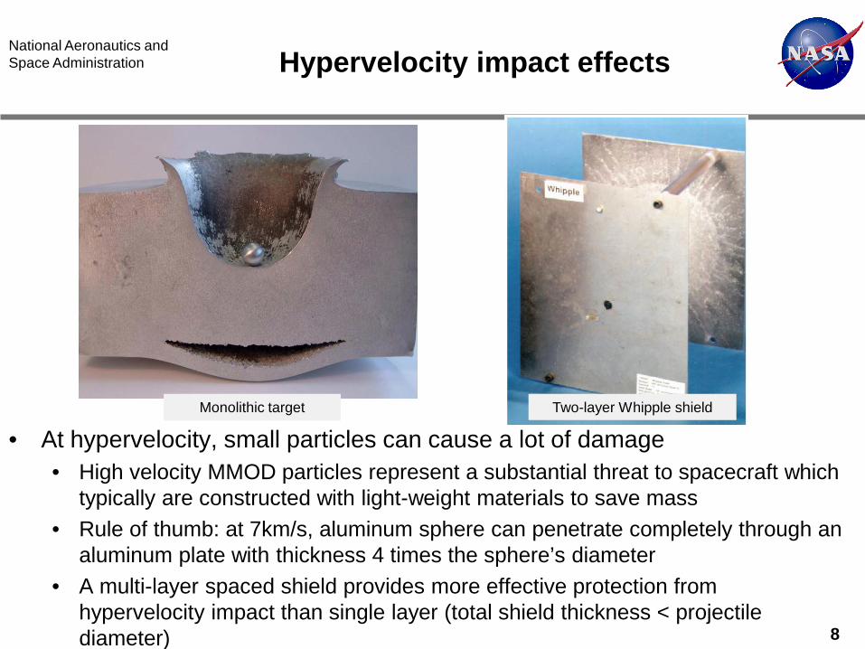
• At hypervelocity, small particles can cause a lot of damage • High velocity MMOD particles represent a substantial threat to spacecraft which
typically are constructed with light-weight materials to save mass • Rule of thumb: at 7km/s, aluminum sphere can penetrate completely through an
aluminum plate with thickness 4 times the sphere’s diameter • A multi-layer spaced shield provides more effective protection from
hypervelocity impact than single layer (total shield thickness < projectile diameter)
Monolithic target Two-layer Whipple shield
9
National Aeronautics and Space Administration ISS MMOD protection approach
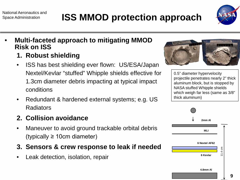
• Multi-faceted approach to mitigating MMOD Risk on ISS 1. Robust shielding • ISS has best shielding ever flown: US/ESA/Japan
Nextel/Kevlar “stuffed” Whipple shields effective for 1.3cm diameter debris impacting at typical impact conditions
• Redundant & hardened external systems; e.g. US Radiators
2. Collision avoidance • Maneuver to avoid ground trackable orbital debris
(typically ≥ 10cm diameter)
3. Sensors & crew response to leak if needed • Leak detection, isolation, repair
2mm Al
MLI
6 Nextel AF62
6 Kevlar
4.8mm Al
11.4
cm
0.5” diameter hypervelocity projectile penetrates nearly 2” thick aluminum block, but is stopped by NASA stuffed Whipple shields which weigh far less (same as 3/8” thick aluminum)
10
National Aeronautics and Space Administration
Shielding Design and Verification Methodology
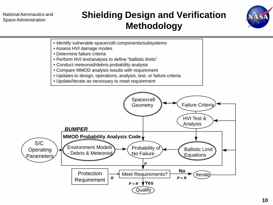
Probability of No Failure
Environment Models - Debris & Meteoroid
Spacecraft Geometry
Ballistic Limit Equations
MMOD Probability Analysis Code
Failure Criteria
HVI Test & Analysis
Meet Requirements?
Qualify Yes
Iterate No
S/C Operating
Parameters
• Identify vulnerable spacecraft components/subsystems • Assess HVI damage modes • Determine failure criteria • Perform HVI test/analysis to define “ballistic limits” • Conduct meteoroid/debris probability analysis • Compare MMOD analysis results with requirement • Updates to design, operations, analysis, test, or failure criteria • Update/Iterate as necessary to meet requirement
Protection Requirement
P
R P > R
P < R
BUMPER
11
National Aeronautics and Space Administration
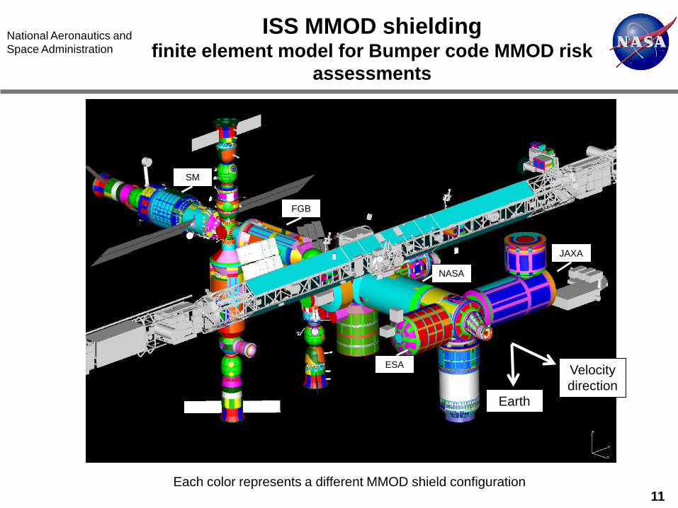
ISS MMOD shielding finite element model for Bumper code MMOD risk
assessments
Each color represents a different MMOD shield configuration
Earth
Velocity direction
FGB
SM
NASA
JAXA
ESA
12
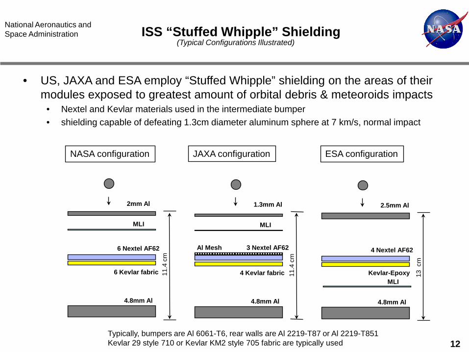
National Aeronautics and Space Administration ISS “Stuffed Whipple” Shielding
• US, JAXA and ESA employ “Stuffed Whipple” shielding on the areas of their modules exposed to greatest amount of orbital debris & meteoroids impacts
• Nextel and Kevlar materials used in the intermediate bumper • shielding capable of defeating 1.3cm diameter aluminum sphere at 7 km/s, normal impact
NASA configuration JAXA configuration ESA configuration
2mm Al
MLI
6 Nextel AF62
6 Kevlar fabric
4.8mm Al
11.4
cm
1.3mm Al
MLI
3 Nextel AF62
4 Kevlar fabric
4.8mm Al 11
.4 c
m
2.5mm Al
MLI
4 Nextel AF62
Kevlar-Epoxy
4.8mm Al
13 c
m
Al Mesh
(Typical Configurations Illustrated)
Typically, bumpers are Al 6061-T6, rear walls are Al 2219-T87 or Al 2219-T851 Kevlar 29 style 710 or Kevlar KM2 style 705 fabric are typically used
13
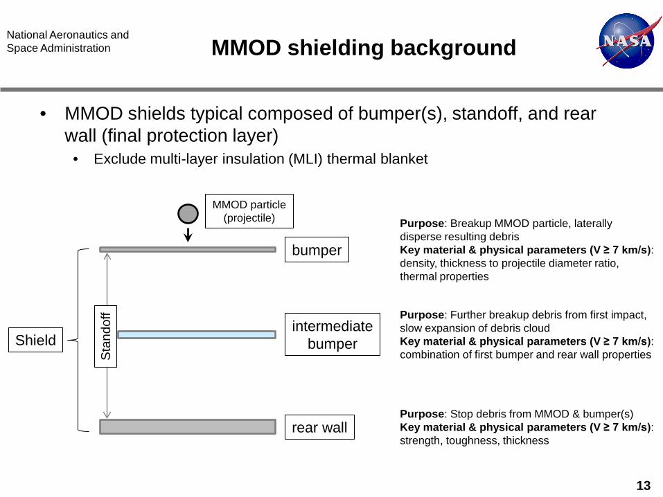
National Aeronautics and Space Administration MMOD shielding background
• MMOD shields typical composed of bumper(s), standoff, and rear wall (final protection layer)
• Exclude multi-layer insulation (MLI) thermal blanket
Shield
bumper
intermediate bumper
rear wall
Sta
ndof
f
Purpose: Breakup MMOD particle, laterally disperse resulting debris Key material & physical parameters (V ≥ 7 km/s): density, thickness to projectile diameter ratio, thermal properties
MMOD particle (projectile)
Purpose: Further breakup debris from first impact, slow expansion of debris cloud Key material & physical parameters (V ≥ 7 km/s): combination of first bumper and rear wall properties
Purpose: Stop debris from MMOD & bumper(s) Key material & physical parameters (V ≥ 7 km/s): strength, toughness, thickness
14
National Aeronautics and Space Administration
15
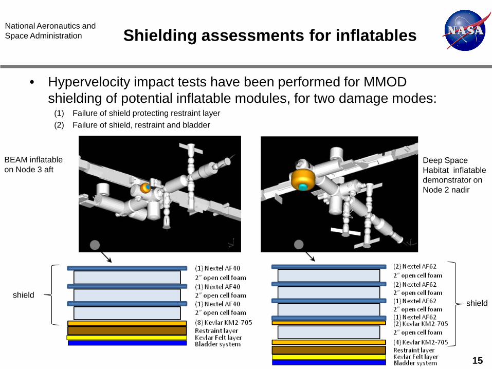
National Aeronautics and Space Administration Shielding assessments for inflatables
• Hypervelocity impact tests have been performed for MMOD shielding of potential inflatable modules, for two damage modes:
(1) Failure of shield protecting restraint layer (2) Failure of shield, restraint and bladder
BEAM inflatable on Node 3 aft
Deep Space Habitat inflatable demonstrator on Node 2 nadir
shield shield
16
National Aeronautics and Space Administration Summary
• MMOD shielding capability influenced by both: 1. Configuration – “standoff” (more is better), number of bumper shield
layers 2. Material selection – ceramics/metals on exterior of shield, high-strength
to weight ratio (fabrics & composites) on interior of shield
• More information available: • NASA TP-2003-210788, Meteoroid/Debris Shielding • NASA TM-2009-214785, Handbook for Designing MMOD Protection • NASA TM-2003-212065, Integration of MMOD Impact Protection
Strategies into Conceptual Spacecraft Design • NASA TM-2009-214789, MMOD Shield Ballistic Limit Analysis Program
17
National Aeronautics and Space Administration
Backup Charts
National Aeronautics and Space Administration
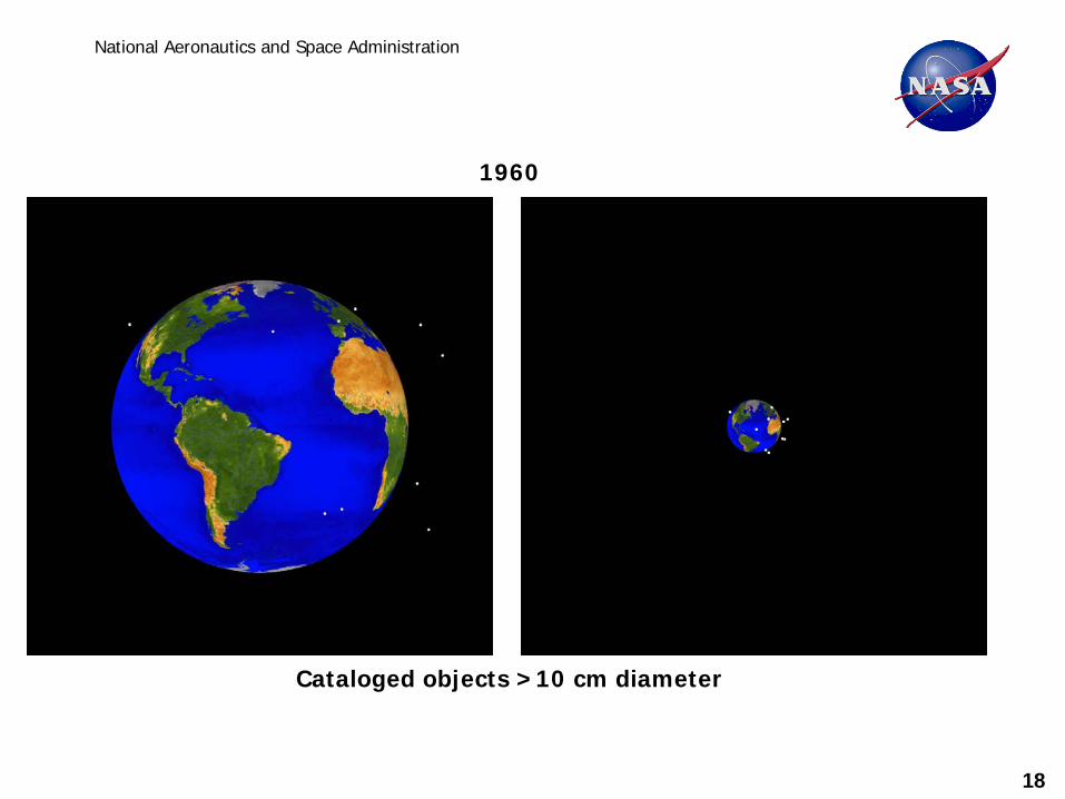
Cataloged objects >10 cm diameter
1960
18
National Aeronautics and Space Administration
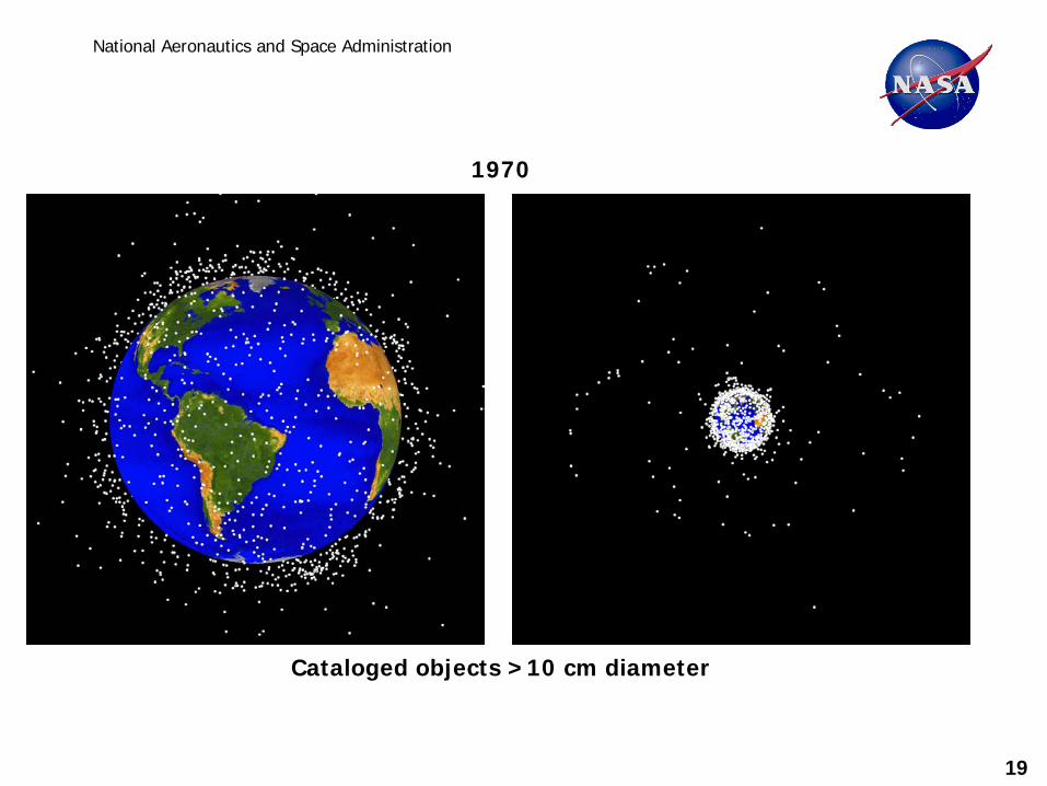
Cataloged objects >10 cm diameter
1970
19
National Aeronautics and Space Administration
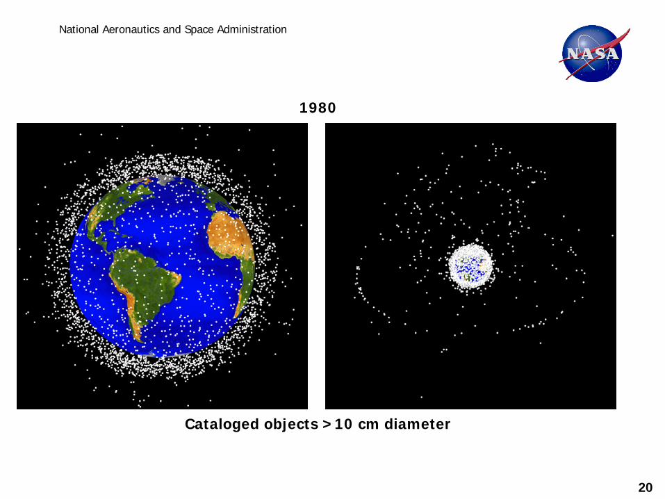
Cataloged objects >10 cm diameter
1980
20
National Aeronautics and Space Administration
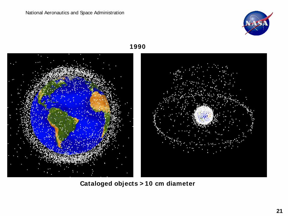
Cataloged objects >10 cm diameter
1990
21
National Aeronautics and Space Administration
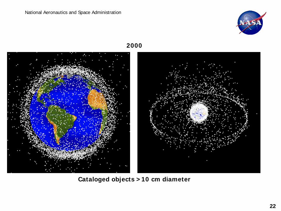
Cataloged objects >10 cm diameter
2000
22
National Aeronautics and Space Administration
Cataloged objects >10 cm diameter
August 2009
23
24
National Aeronautics and Space Administration
0
0.1
0.2
0.3
0.4
0.5
0.6
0.7
0.8
0 2 4 6 8 10 12 14Velocity (km/s)
Crit
ical
Al D
iam
eter
(cm
Whipple dcrit @ 0 degmonolithic dcrit @ 0 deg
Ballistic Regime Fragmentation &
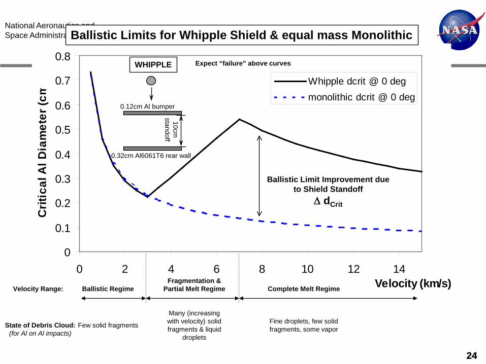
Partial Melt Regime Complete Melt Regime Velocity Range:
State of Debris Cloud: (for Al on Al impacts)
Few solid fragments
Many (increasing with velocity) solid fragments & liquid
droplets
Fine droplets, few solid fragments, some vapor
Ballistic Limit Improvement due to Shield Standoff
∆ dCrit
Expect “failure” above curves
0.12cm Al bumper
0.32cm Al6061T6 rear wall
10cm
standoff
WHIPPLE
Ballistic Limits for Whipple Shield & equal mass Monolithic
24
25
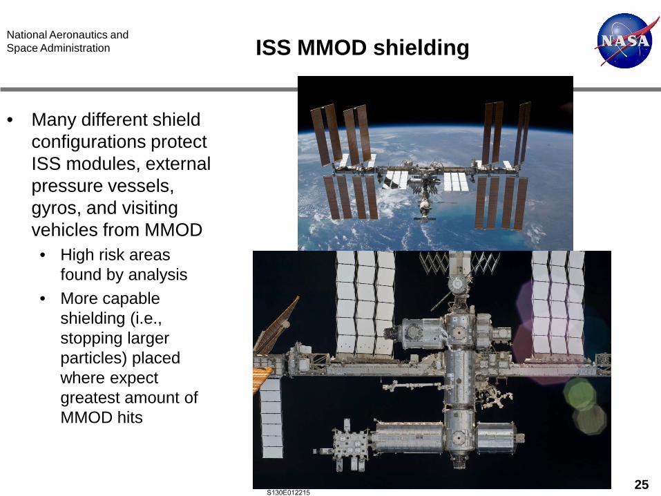
National Aeronautics and Space Administration ISS MMOD shielding
• Many different shield configurations protect ISS modules, external pressure vessels, gyros, and visiting vehicles from MMOD • High risk areas
found by analysis • More capable
shielding (i.e., stopping larger particles) placed where expect greatest amount of MMOD hits
26
National Aeronautics and Space Administration Shielding materials
• Nextel (3M Inc. trade mark): fabric consisting of alumina-boria-silica ceramic fibers • Other ceramic and glass fabrics tested, and will provide adequate
MMOD protection (substitute equal mass for Nextel) • Kevlar aramid fabric: highest hypervelocity protection performance
found using Kevlar KM2 fabrics • Other high-strength to weight materials incorporated in MMOD shields
include Spectra, Vectran, carbon fabric and carbon-composites
27
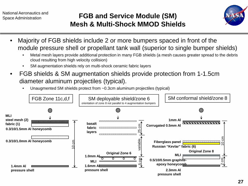
National Aeronautics and Space Administration FGB and Service Module (SM)
Mesh & Multi-Shock MMOD Shields
• Majority of FGB shields include 2 or more bumpers spaced in front of the module pressure shell or propellant tank wall (superior to single bumper shields)
• Metal mesh layers provide additional protection in many FGB shields (a mesh causes greater spread to the debris cloud resulting from high velocity collision)
• SM augmentation shields rely on multi-shock ceramic fabric layers
• FGB shields & SM augmentation shields provide protection from 1-1.5cm diameter aluminum projectiles (typical).
• Unaugmented SM shields protect from ~0.3cm aluminum projectiles (typical)
FGB Zone 11c,d,f SM deployable shield/zone 6 orientation of zone 8 not parallel to 4 augmentation bumpers
0.3/10/1.5mm Al honeycomb
MLI steel mesh (2) fabric (1)
1.4mm Al pressure shell
10 c
m
MLI
basalt fabric layers
Original Zone 6 1.0mm Al
25 c
m
0.3/10/1.0mm Al honeycomb
1.6mm Al pressure shell
5 cm
va
riabl
e
SM conformal shield/zone 8
Original Zone 8 MLI
0.5/10/0.5mm graphite-epoxy honeycomb
2.3mm Al pressure shell
2 cm
1mm Al Corrugated 0.5mm Al
Russian “Kevlar” fabric (6) 10 c
m
Fiberglass panel
28
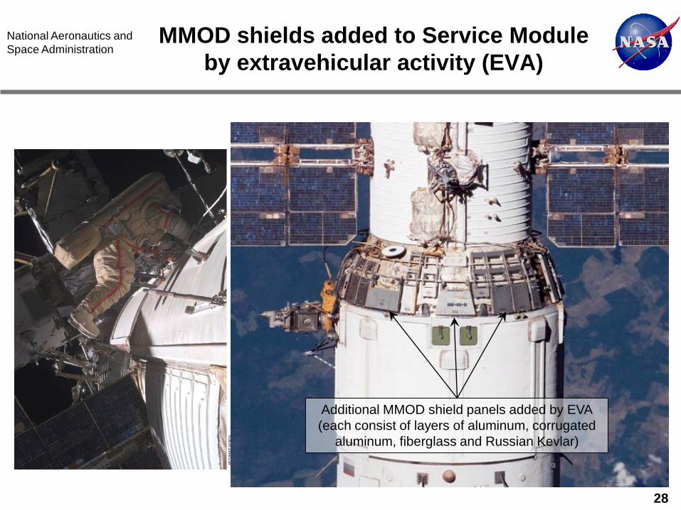
National Aeronautics and Space Administration
MMOD shields added to Service Module by extravehicular activity (EVA)
Additional MMOD shield panels added by EVA (each consist of layers of aluminum, corrugated
aluminum, fiberglass and Russian Kevlar)