Embed Size (px)
Citation preview
J O U R N A L O F M A T E R I A L S S C I E N C E 19 ( 1 9 8 4 ) 3 6 1 2 - - 3 6 1 9
Micromechanics of fracture in elastomers
A. N. G E N T * , C . T. R. PULFORD t Institute of Polymer Science, The University of Akron, Akron, Ohio 44325, USA
A study of torn surfaces and the tips of propagating tears in elastomers has been carried out using scanning electron microscopy. Vertical steps separating smooth featureless torn regions are characteristic features of the torn surfaces. They are found to be more fre- quent and larger in stronger elastomers. They are attributed to the intersection of second- ary cracks at the tear tip, disNaced somewhat from the general tear plane, and nucleated by inherent stress-raisers. The effective diameter of the tear tip is thereby increased. Stress-raising features are inferred to be present in elastomeric materials at a typical spacing of 10 to 100 #m. In carbon-black-illled elastomers, the carbon particles them- selves are found to nucleate secondary cracks profusely.
1. Introduction Much can be learnt about mechanisms of failure from a study of fracture surfaces. However, the torn surfaces of elastomers have received little attention up to the present time. Thomas has pointed out on theoretical grounds that the tear strength will be directly related to the bluntness of the tear tip, measured by the radius of curva- ture of an idealized tear tip in the unstrained state [1]. A rough torn surface is then indicative of a blunt tear and a smooth torn surface is indicative of a sharp tear. Indeed, a general correlation is found to hold between the measured tear strength and the observed roughness of the torn surface, on a scale of 0.1 to 1 mm [2, 3]. Roughness on a still larger scale has been observed under certain con- ditions of tearing in rubber reinforced with carbon black, the tear curving away from the original plane of propagation to such a degree that it stops altogether and a new tear tip must form [2, 3]. This discontinuous, so-called "knotty", tearing leaves relatively smooth torn surfaces between the "knots". The tear force also oscillates between high values at the arrest points and low values in the smoothly-propagating regions.
A minimum or threshold strength of elastomers is observed at high temperatures and low rates of tearing, when the torn surfaces are relatively
smooth [4-6]. Moreover, this threshold strength, of the order of 50 J m -2, is in reasonably good accord with a simple molecular theory in which the tear tip diameter is given its minimum possible size, about 10nm, corresponding to the distance between the ends of macromolecular strands in the molecular network comprising the cross- linked elastomer [7].
Thus, there is substantial evidence for a general relationship between the tear strength of rubber and the roughness of the torn surface. In contrast to this viewpoint however, Fukahori and Andrews have recently suggested that an inverse correlation holds [8]. They propose that both properties are related to the mechanical hysteresis of the material, the tear strength by a direct relationship, as is widely accepted [9-11], and the surface rough- ness by an inverse relationship. They attribute surface roughness to the formation of secondary cracks ahead of the main tear front, as proposed by Smekal [12] and suggest that the size of the zone in which secondary cracking takes place is a decreasing function of the degree of mechanical hysteresis.
Small-scale surface irregularities of some com- plexity are found on the fracture surface of torn elastomers [13-15]. There is clearly a need for a detailed study of these features of the tear process,
*Visiting Professor, Department of Chemical Engineering, McGill University, Montreal, Fall Term, 1983. tPresent address: Materials Physics Section, Research Division, Goodyear Tire and Rubber Company, Akron, Ohio 44316, USA.
3612 0022-2461/84 $03.00 + .12 �9 1984 Chapman and Hall Ltd.
and of the relationship between surface roughness and the observed strength. Fracture surfaces of some representative elastomers torn under various conditions have therefore been examined by scanning electron microscopy. In addition, the tip of a propagating tear has been studied using a tech- nique devised by Bascom [13]. These observations are described here and accounted for by means of a simple micromechanical model of local tear processes.
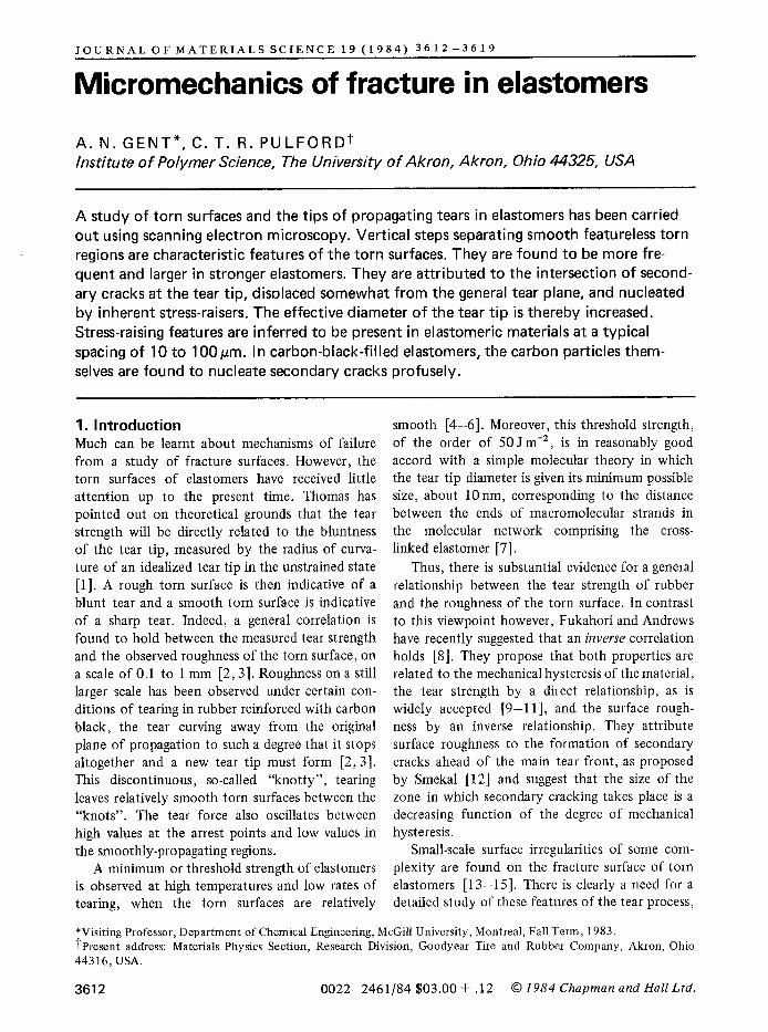
2. Experimental procedure Sheets of rubber, about 1.5 mm thick, were made using the mix formulations and vulcanization con- ditions given in the Appendix. Sample strips, about 7.5 mm wide and 25 mm long, were cut from the sheets. Each strip was cut about half-way through along a centre line by scoring it with a sharp blade. It was then bent back with the cut surface outwards so that tearing took place at the tip of the cut at a rate governed by the bending stresses developed there (Fig. 1). Somewhat similar rates of tearing, between 0.5 and 2 mm sec -1 , were employed with elastomers of widely differing tear strength by varying the degree of bending. The torn surfaces were then gold-coated in a vacuum evaporator and examined by scanning electron microscopy.
An alternative procedure, described by Bascom [13], was employed to study the tear tip itself. In this case the scored strip was bent back over a metal plate and tied in the bent state with wire. As the tear propagated from the initial cut it ran into regions of lower stress and eventually stopped. The sample was gold-coated at this point and examined in the bent state.
(a)
jl I
(b)
Figure 1 Test-pieces employed for SEM studies. (a) Tear tip; (b) torn surface.
Some samples were swollen with paraffin oil and torn in the swollen state. The paraffin oil was then extracted from the sample with acetone before microscopy.
3. Nature of the tear process All unfilled elastomers appeared to tear in the same way. This process is illustrated here in the simplest case, a non-crystallizing mixed-isomer polybutadiene (Diene 35 NFA, Firestone Tire and Rubber Company) cross-linked with a free-radical source, dicumyl peroxide (formulation A in the Appendix).
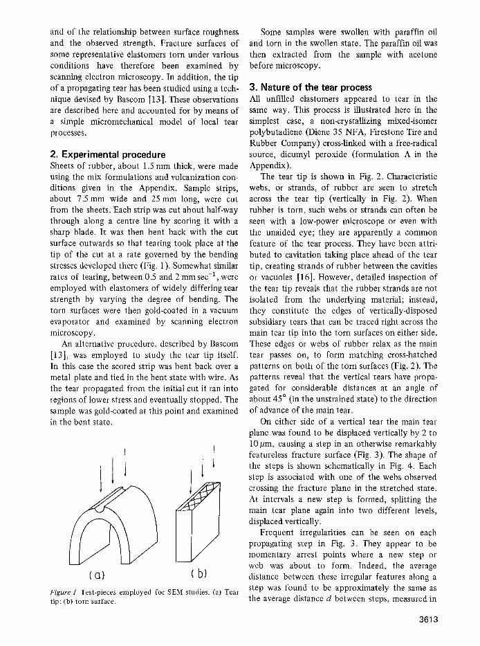
The tear tip is shown in Fig. 2. Characteristic webs, or strands, of rubber are seen to stretch across the tear tip (vertically in Fig. 2). When rubber is torn, such webs or strands can often be seen with a low-power microscope or even with the unaided eye; they are apparently a common feature of the tear process. They have been attri- buted to cavitation taking place ahead of the tear tip, creating strands of rubber between the cavities or vacuoles [16]. However, detailed inspection of the tear tip reveals that the rubber strands are not isolated from the underlying material; instead, they constitute the edges of vertically-disposed subsidiary tears that can be traced right across the main tear tip into the torn surfaces on either side. These edges or webs of rubber relax as the main tear passes on, to form matching cross-hatched patterns on both of the torn surfaces (Fig. 2). The patterns reveal that the vertical tears have propa- gated for considerable distances at an angle of about 45 ~ (in the unstrained state) to the direction of advance of the main tear.
On either side of a vertical tear the main tear plane was found to be displaced vertically by 2 to 10/Jm, causing a step in an otherwise remarkably featureless fracture surface (Fig. 3). The shape of the steps is shown schematically in Fig. 4. Each step is associated with one of the webs observed crossing the fracture plane in the stretched state. At intervals a new step is formed, splitting the main tear plane again into two different levels, displaced vertically.
Frequent irregularities can be seen on each propagating step in Fig. 3. They appear to be momentary arrest points where a new step or web was about to form. Indeed, the average distance between these irregular features along a step was found to be approximately the same as the average distance d between steps, measured in
3613
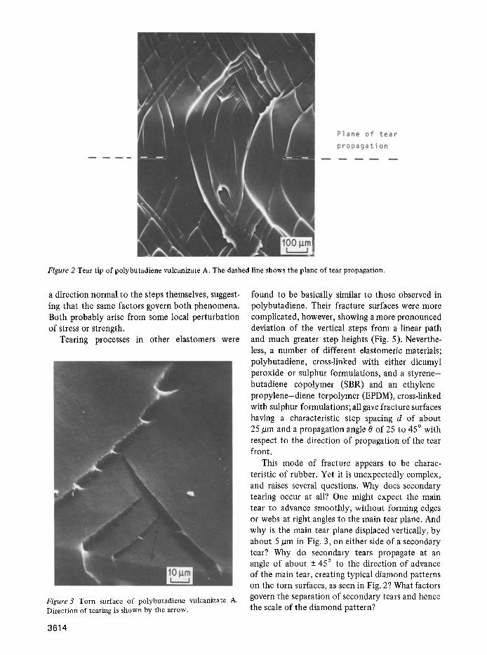
Figure 2 Tear tip of polybutadiene vulcanizate A. The dashed line shows the plane of tear propagation.
a direction normal to the steps themselves, suggest- ing that the same factors govern both phenomena. Both probably arise from some local perturbation of stress or strength.
Tearing processes in other elastomers were
Figure3 Torn surface of polybutadiene vulcanizate A. Direction of tearing is shown by the arrow.
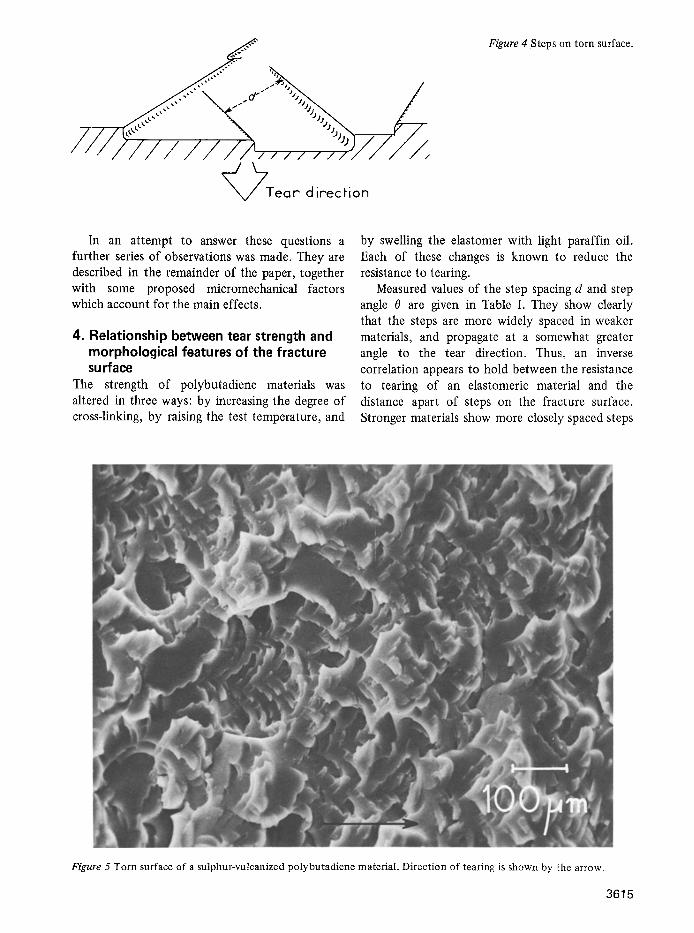
found to be basically similar to those observed in polybutadiene. Their fracture surfaces were more complicated, however, showing a more pronounced deviation of the vertical steps from a linear path and much greater step heights (Fig. 5). Neverthe- less, a number of different elastomeric materials; polybutadiene, cross-linked with either dicumyl peroxide or sulphur formulations, and a styrene- butadiene copolymer (SBR) and an ethylene- propylene-diene terpolymer (EPDM), cross-linked with sulphur formulations; all gave fracture surfaces having a characteristic step spacing d of about 25/ira and a propagation angle 0 of 25 to 45 ~ with respect to the direction of propagation of the tear front.
This mode of fracture appears to be charac- teristic of rubber. Yet it is unexpectedly complex, and raises several questions. Why does secondary tearing occur at all? One might expect the main tear to advance smoothly, without forming edges or webs at right angles to the main tear plane. And why is the main tear plane displaced vertically, by about 5 pm in Fig. 3, on either side of a secondary tear? Why do secondary tears propagate at an angle of about + 45 ~ to the direction of advance of the main tear, creating typical diamond patterns on the torn surfaces, as seen in Fig. 2? What factors govern the separation of secondary tears and hence the scale of the diamond pattern?
3614
__,_,__,~..,,,,,'" --,, ,+
//////////?,,,,, , .U/Y/
~Tear direction
Figure 4 Steps on torn surface.
In an attempt to answer these questions a further series of observations was made. They are described in the remainder of the paper, together with some proposed micromechanical factors which account for the main effects.
4. Relationship between tear strength and morphological features of the fracture su rface
The strength of polybutadiene materials was altered in three ways: by increasing the degree of cross-linking, by raising the test temperature, and
by swelling the elastomer with fight paraffin oil. Each of these changes is known to reduce the resistance to tearing.
Measured values of the step spacing d and step angle 0 are given in Table I. They show clearly that the steps are more widely spaced in weaker materials, and propagate at a somewhat greater angle to the tear direction. Thus, an inverse correlation appears to hold between the resistance to tearing of an elastomeric material and the distance apart of steps on the fracture surface. Stronger materials show more closely spaced steps
Figure 5 Torn surface of a sulphur-vulcanized polybutadiene material. Direction of tearing is shown by the arrow.
3615
Formulation Temperature d 0 (~ C) (pm) (degrees)
A (0.05% dicumyl peroxide) --20 15 25
25 30 30 90 50 35
(c)
B (0.2% dicumyl peroxide) 25 100 45
A, swollen with paraffin oil, 160 per cent by volume 25 240 40
whereas weaker materials show smooth torn areas, extending over large distances, with no distinct features greater than about 0.1 pm in size.
However, this general correlation does not appear to apply to strain-crystallizing elastomers, such as natural rubber, which are much more resistant to tearing than the wholly amorphous elastomers considered so far. The step spacing for a natural rubber vulcanizate was found to be quite comparable in size to that for amorphous materials, ranging from 10 to 100 pro, even though its tear resistance is much greater.
Another feature shown by tear-resistant materials is a greater height of the steps on frac- ture surfaces, so that the tear plane propagates on levels separated by considerable distances. Clearly, a propagating tear tip is rendered effectively less sharp both by closely spaced steps and by larger step heights. Both features appear to be present in stronger elastomers and cause an effective blunting of the tear tip on a microscopic scale. We now consider how the micromechanics of tearing leads to these morphological features.
5. Proposed mechanism for step and web formation
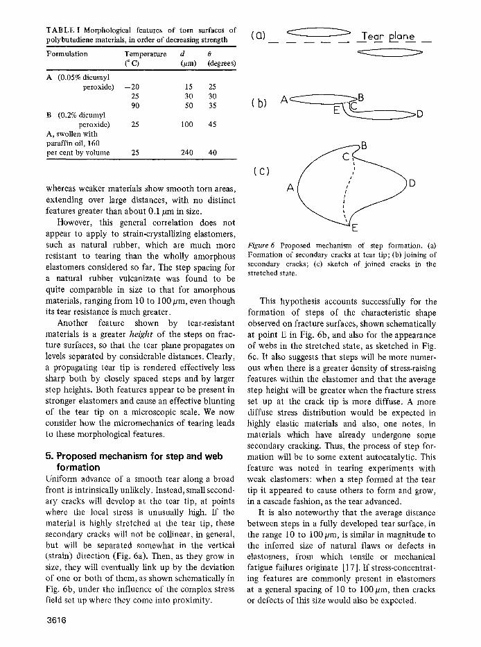
Uniform advance of a smooth tear along a broad front is intrinsically unlikely. Instead, small second- ary cracks will develop at the tear tip, at points where the local stress is unusually high. If the material is highly stretched at the tear tip , these secondary cracks will not be collinear, in general, but will be separated somewhat in the vertical (strain) direction (Fig. 6a). Then, as they grow in size, they will eventually link up by the deviation of one or both of them, as shown schematically in Fig. 6b, under the influence of the complex stress field set up where they come into proximity.
3616
(CI)__ . . . . . . ~ Tear" plane
(b) A~--~IC~ E __~D
B
A
TABLE I Morphological features of torn surfaces of polybutadiene materials, in order of decreasing strength
D
Figure 6 Proposed mechanism of step formation. (a) Formation of secondary cracks at tear tip; (b) joining of secondary cracks; (c) sketch of joined cracks in the stretched state.
This hypothesis accounts successfully for the formation of steps of the characteristic shape observed on fracture surfaces, shown schematically at point E in Fig. 6b, and also for the appearance of webs in the stretched state, as sketched in Fig. 6c. It also suggests that steps will be more numer- ous when there is a greater density of stress-raising features within the elastomer and that the average step height will be greater when the fracture stress set up at the crack tip is more diffuse. A more diffuse stress distribution would be expected in highly elastic materials and also, one notes, in materials which have already undergone some secondary cracking. Thus, the process of step for- mation will be to some extent autocatalytic. This feature was noted in tearing experiments with weak elastomers: when a step formed at the tear tip it appeared to cause others to form and grow, in a cascade fashion, as the tear advanced.
It is also noteworthy that the average distance between steps in a fully developed tear surface, in the range 10 to 100 pro, is similar in magnitude to the inferred size of natural flaws or defects in elastomers, from which tensile or mechanical fatigue failures originate [17]. If stress-concentrat- ing features are commonly present in elastomers at a general spacing of 10 to 100pm, then cracks or defects of this size would also be expected.
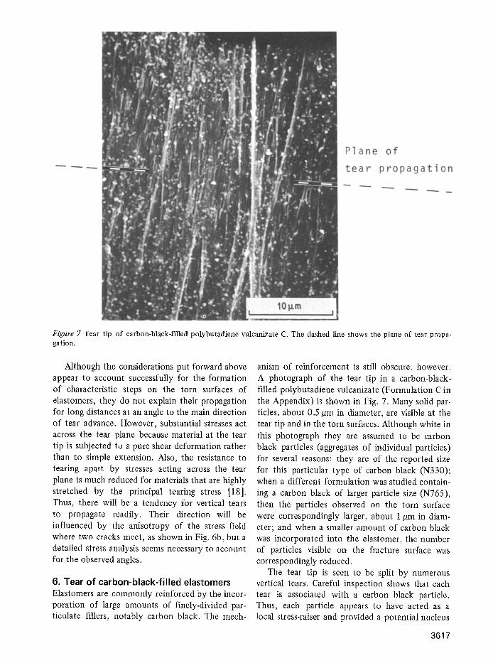
Figure 7 Tear tip of carbon-black-filled polybutadiene vulcanizate C. The dashed line shows the plane of tear propa- gation.
Although the considerations put forward above appear to account successfully for the formation of characteristic steps on the torn surfaces of elastomers, they do not explain their propagation for long distances at an angle to the main direction of tear advance. However, substantial stresses act across the tear plane because material at the tear tip is subjected to a pure shear deformation rather than to simple extension. Also, the resistance to tearing apart by stresses acting across the tear plane is much reduced for materials that are highly stretched by the principal tearing stress [18]. Thus, there will be a tendency for vertical tears to propagate readily. Their direction will be influenced by the anisotropy of the stress field where two cracks meet, as shown in Fig. 6b, but a detailed stress analysis seems necessary to account for the observed angles.
6. Tear of carbon-black-filled elastomers Elastomers are commonly reinforced by the incor- poration of large amounts of finely-divided par- ticulate fillers, notably carbon black. The mech-
anism of reinforcement is still obscure, however. A photograph of the tear tip in a carbon-black- filled polybutadiene vulcanizate (Formulation C in the Appendix) is shown in Fig. 7. Many solid par- ticles, about 0.5 #m in diameter, are visible at the tear tip and in the torn surfaces. Although white in this photograph they are assumed to be carbon black particles (aggregates of individual particles) for several reasons: they are of the reported size for this particular type of carbon black (N330); when a different formulation was studied contain- ing a carbon black of larger particle size (N765), then the particles observed on the torn surface were correspondingly larger, about 1/lm in diam- eter; and when a smaller amount of carbon black was incorporated into the elastomer, the number of particles visible on the fracture surface was correspondingly reduced.
The tear tip is seen to be split by numerous vertical tears. Careful inspection shows that each tear is associated with a carbon black particle. Thus, each particle appears to have acted as a local stress-raiser and provided a potential nucleus
3617
for a secondary crack. The reinforcing action of carbon black thus appears to consist, paradoxi- cally, of inducing many small tears to form in the highly strained material at the tear tip, and in this way to blunt the effective tip diameter [19].
The particle size is extremely important for this reinforcement mechanism to operate. If the par- ticles are much smaller than 1/zm, say, then detachment or tearing in their vicinity becomes improbable because the stresses required become extremely large [20, 21 ]. On the other hand, when the particles are much larger than about 1/~m, then they do not confer significant advantages because unfilled elastomers appear to have inherent stress-raising defects at spacings of 10 to 100/~m, as discussed earlier.
The characteristic marked deviation of a tear in reinforced elastomers from a linear path under some circumstances, so that the effective tip diameter becomes several mm and a new tear must form ("knotty" or "stick-slip" tearing)is not accounted for by the micromechanical consider- ations discussed above. They apply to relatively smooth tearing of filled material, for example, when the tear progresses for relatively short dis- tances, or when tearing takes place at high speeds or at high temperatures, and the filled material is some three times more tear resistant than the corresponding unfilled materials [3,22]. Knotty tearing, when the tear resistance becomes as much as ten times greater, is still unexplained.
7. Conclusions There seems to be a natural tendency for tears in rubber to deviate from a straight path. Complicated fracture surfaces are formed with pronounced splitting in a direction perpendicular to the main tear plane. The splitting is more frequency in stronger materials and runs for longer distances so that the effective diameter of the tear tip is greatly enlarged in comparison with a single sharp tear. A tentative mechanism to account for this splitting, and for the characteristic steps that it gives rise to on torn surfaces, has been proposed in terms of a natural distribution of local stress- raising features at a spacing of the order of 10 to lO0/am. The nature of these stress-concentrating features is unknown. However, the enormously increased density of splitting in carbon-black- filled rubber is attributed to nucleation by carbon black particles of similar secondary cracks.
The proposed mechanism of vertical splitting
3618
of the main tear as a result of the joining up of secondary tears within the main tear front, Fig. 6, must be clearly distinguished from that discussed by Fukahori and Andrews [8], following Smekal [12]. They consider the main tear to link up with secondary cracks located ahead of it. No evidence was found for this process in the torn surfaces studied here.
Appendix The following mix formulations in parts by weight and vulcanization conditions were employed for preparing test specimens.
A. Polybutadiene (Diene 35 NFA, Firestone Tire and Rubber Company), 100; dicumyl per- oxide, 0.05. Heated for 120 min at 150 ~ C.
B. Polybutadiene, 100; dicumyl peroxide, 0.2. Heated for 120 rain at 150 ~ C.
C. Polybutadiene, 100; N330 carbon black (Vul- can 3, Cabot Corporation), 50; zinc oxide, 3.5; stearic acid, 2.5; Philrich HA5, 5; phenyl- 2-naphthylamine, 1; Santocure MOR, 0.6; sulphur, 2. Heated for 60 min at 150 ~ C.
Acknowledgements This work was initiated under a research grant from the Engineering Division of the National Science Foundation (NSF-ENG-16982) and com- pleted under a research grant from the Office of Naval Research (ONR-N00014-76-C-0408), while one of the authors (ANG) was a Visiting Professor in the Department of Chemical Engineering at McGill University, Montreal. The hospitality of the department and its head, Dr M. F. Kamal, is warmly appreciated. Additional support of this research by Cabot Corporation is also gratefully acknow- ledged.
References 1. A . G . THOMAS, J. PolymerSci. 18 (1955) 177. 2. H.W. GREENSMITH, ibid. 21 (1956) 175. 3. ldem, J. Appl. Polymer Sci. 3 (1960) 183. 4. H .K . MUELLER and W. G. KNAUSS, Trans. Soc.
Rheol. 15 (1971) 217. 5. A. AHAGON and A. N. GENT, J. Polymer Sci. Poly-
merPhys, Ed. 13 (1975) 1903. 6. A .N . GENT and R .H . TOBIAS, ibid. 20 (1982)
2317. 7. G . J . LAKE and A. G. THOMAS, Proc. Roy. Soc.
London A300 (1967) 108. 8. Y. FUKAHORI and E. H. ANDREWS, J. Mater. Sci.
13 (1978) 777.
9. L. MULLINS, Trans. Inst. Rubber Ind. 35 (1959) 213.
10. H.W. GREENSMITH, L. MULLINS and A.G. THOMAS, in "The Chemistry and Physics of Rubberlike Substances", edited by L. Bateman (Wiley, New York, 1963) Ch. 10, pp. 249-299.
11. E. H. ANDREWS,,/.. Mater. Sci. 9 (1974) 887. 12. A. SMEKAL, Ergeb. d. Exact. Naturw. 15 (1936)
106. 13. w.D. BASCOM, Rubber Chem. Teehnol. 50 (1977)
875. 14. A.K. BHOWMICK, G.B. NANDO, S. BASU and
S. K. DE, ibid. 53 (1980) 327. 15. D.K. SETUA and S. K. BE, J. Mater. Sci. 18 (1983)
847. 16. H.H. KAUSCH, "Polymer Fracture" (Springer-
Verlag, New York, 1978) p. 237.
17. A.N. GENT, P. B. LINDLEY and A. G. THOMAS, d. Appl. Polymer Sci. 8 (1964) 455.
18. A.N. GENT and H. 3. KIM, Rubber Chem. Technol. 51 (1978) 35.
19. A.E. OBERTH and R. S. BRUENNER, Trans. Soc. Rheol. 9 (1965) 165.
20. A.N. GENT, J. Mater. Sei. 15 (1980) 2884. 21. A.N. GENT and BYOUNGKYEU PARK, ibid, 19
(1984) 1947. 22. A.N. GENT and A. W. HENRY, Proceedings of the
International Rubber Conference, 1967 (Maclaren and Sons, London, 1968) pp. 193-204.
Received 29 December 1983
and accepted 18 January 1984
3619

![PANEL ON MICROMECHANICS AND PHYSICS OF FRACTURE · plastic deformation process itself [ 3 ], (4) the study of atomistic processes of fracture, with special regard to the influences](https://img.pdfslide.us/doc/110x75/5e2867747c363d40ad2ad960/panel-on-micromechanics-and-physics-of-fracture-plastic-deformation-process-itself.jpg)