Embed Size (px)
Citation preview

SIGALARM
MODEL 210
MicroGuard 434
SERVICE MANUAL


SkyAzúl, Equipment Solutions www.skyazul.com 301-371-6126
NOTICE SkyAzúl makes no warranty of any kind with regard to this material, including, but not limited to, the implied warranties of merchantability and/or its fitness for a particular purpose.
SkyAzúl will not be liable for errors contained in this manual or for incidental or consequential damages in connection with the furnishing, performance, or use of this manual. This document contains proprietary information, which is protected by copyright, and all rights are reserved.
No part of this document may be photocopied, reproduced, or translated to another language without the prior written consent of SkyAzúl.
SkyAzúl reserves proprietary rights to all drawings, photos and the data contained therein. The drawings, photos and data are confidential and cannot be used or reproduced without the written consent of SkyAzúl. The drawings and/or photos are subject to technical modification without prior notice.
All information in this document is subject to change without notice.
SkyAzúl, Inc. 16 Walnut Street Middletown, MD 21769 Fax 301-371-0029 [email protected]

SkyAzúl, Equipment Solutions www.skyazul.com 301-371-6126
SkyAzúl, Equipment Solutions www.skyazul.com 301-371-6126
3
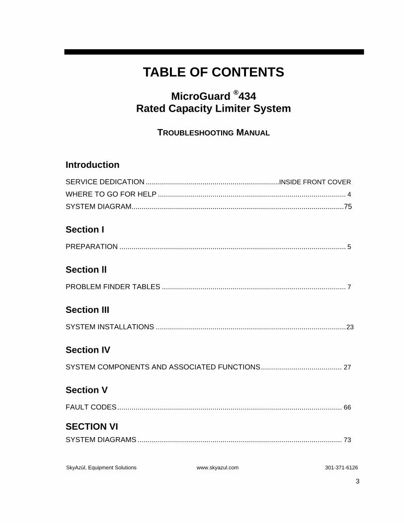
TABLE OF CONTENTS MicroGuard ®434
Rated Capacity Limiter System
TROUBLESHOOTING MANUAL
Introduction
SERVICE DEDICATION ..................................................................INSIDE FRONT COVER
WHERE TO GO FOR HELP ............................................................................................. 4
SYSTEM DIAGRAM.........................................................................................................75
Section I
PREPARATION ................................................................................................................ 5
Section ll
PROBLEM FINDER TABLES ........................................................................................... 7
Section III
SYSTEM INSTALLATIONS ..............................................................................................23
Section IV
SYSTEM COMPONENTS AND ASSOCIATED FUNCTIONS........................................ 27
Section V
FAULT CODES............................................................................................................... 66 SECTION VI SYSTEM DIAGRAMS ..................................................................................................... 73

SkyAzúl, Equipment Solutions www.skyazul.com 301-371-6126
4
When field repairs cannot be made without replacement of a part, when troubleshooting advice is needed, or when corrections to
memory chips are reported, one of the following support numbers should be called:
SkyAzúl, Inc.200 W. Main Street, Suite, 2A Middletown, MD 2176
Phone: 301-371-6126 Fax: 301-371-0029 www.skyazul.com [email protected]
WHERE TO GO FOR HELP

SkyAzúl, Equipment Solutions www.skyazul.com 301-371-6126
5
SECTION I PREPARATION This Troubleshooting Manual for the MicroGuard®434 Rated Capacity Limiter System, manufactured by the Greer Company and installed on Link-Belt Construction Equipment Company (LBCE) cranes, provides information and methods for isolating problems that may arise during operation of the System. Some of these problems can be corrected in the field. Other problems may require replacement of parts or a return of a part to the factory for servicing. Persons servicing this System should have prior training and experience in the procedure for operation and setup of this System.
Please refer to the MicroGuard® 434 Operating Instructions in the LBCE Operator’s Manual and/or the MicroGuard® 434 Calibration Manual regarding questions relating to the operation or calibration of this System. Accurate methods must be used to locate a problem. We recommend using the PROBLEM FINDER TABLES in Section II to help locate and define a problem.
The procedures in this manual, where possible, are based on crane operation and function. A basic tool kit consisting of wrenches and screwdrivers (flat and Phillips’ blades) will be required to remove covers and units for inspection. A digital multimeter (DMM) may be required. The DMM must be capable of measuring DC voltage with a range of 0 volts to ± 50 volts and resolution of 0.1 volts. Resistance range is 0 Ohms to 2 Megohms. Low cost analog meters are not appropriate since the input impedance of these meters can give false readings.

SkyAzúl, Equipment Solutions www.skyazul.com 301-371-6126
6
THIS PAGE SHOULD BE BLANK.
SkyAzúl, Equipment Solutions www.skyazul.com 301-371-6126
7
SECTION II
PROBLEM FINDER TABLES
These Problem Finder Tables are designed to aid in determining the location and type of problem experienced. It is important to review these Tables carefully before contacting us.
SYSTEM SELF-TEST................................................................................................................. 8
COMPUTER/DISPLAY COMMUNICATION ......................................................................9-12
DISPLAY OF FAULT CODES ....................................................................................... 13
CRANE MOTIONS ARE DISABLED ............................................................................. 14
ANTI-TWO BLOCK CIRCUIT ........................................................................................ 15
SWING POT SENSOR.................................................................................................. 16
BOOM EXTENSION SENSOR...................................................................................... 17
BOOM ANGLE SENSOR .............................................................................................. 18
PRESSURE TRANSDUCERS...................................................................................19-20
REMOTE BAR GRAPH ................................................................................................. 21

SkyAzúl, Equipment Solutions www.skyazul.com 301-371-6126
8
SYSTEM SELF-TEST
The Computer and Operator’s Display Console do a Self-Test when the power is turned on or during operation when the ”TEST” button is pressed. The Self-Test verifies that the Computer, Display Console, cables, and all remote sensors are working properly.
TEST SEQUENCE FOR DISPLAY CONSOLE:
1. Push TEST BUTTON (T). BLACK BAR GRAPH (B) spans entire window . All lights and all 7 SEGMENT DISPLAYS turn on and the ALARM sounds. Graphic Display (GD) reads: “This is a Test.”
2. If no Fault (problem) is found, the System will start displaying Load, Radius, Angle, etc.
3. Faults discovered during Self-Test will cause the red and yellow lights to turn on. The Graphics Display (GD) will read: “OUT OF SERVICE.”
4. The Operator then presses and holds the TEST button causing the Fault to be identified with a FAULT CODE NUMBER (See Section V) in the Graphics Display.
CAUSES FOR COMMUNICATION FAILURE:
A) Bad connections between the Display Console and the Computer.
B) Incorrect voltage from the Computer to the Display Console.
C) Failure of the serial Transmit/Receive IC in either the Computer, Display Console, or Remote Bar Graph Unit.
D) Failure of the Reset IC in either the Computer or Display Console.
E) The Computer is locked up and not working.
F) The Display is locked up and not working.
FIGURE 2.0 LIQUID CRYSTAL DISPLAYS
B
GD
T

SkyAzúl, Equipment Solutions www.skyazul.com 301-371-6126
9
COMPUTER/DISPLAY COMMUNICATION
Communication problems are difficult to isolate because of the interaction between the Display Console and the Computer. Failure of either unit causes malfunction of the Display Console. Such problems need resolution before using the Problem Finding Tables.
Six wires, identified below and shown in the following diagram, connect the Computer to the Display Console. (See Figure 4.8, page 40.)
FIGURE 2.1 COMMUNICATION BLOCK DIAGRAM
DA Differential serial communication line
DB Differential serial communication line
RES Reset line from the display to the computer
+VP Power to Operator’s Display Console
0V Common return
0V Common return
COMPUTER
DISPLAY CONSOLE
DA
DB
+VP
0V
RESET
TRANSCEIVERIC5
TRANSCEIVERIC6
5 VOLT POWER SUPPLY
5 VOLT REGULATOR
CPU
“TEST” Button
CPU
DISPLAYS BUTTONS
RELAYS
REMOTE BAR GRAPH DADB
+5V0V
SkyAzúl, Equipment Solutions www.skyazul.com 301-371-6126
10
OPERATOR’S DISPLAY CONSOLE
COMPUTER REMOTE BAR GRAPH
READS: ”This is a SELF-TEST.”
After Self-Test, the relays turn on and allow crane
motions.
All lights turn on during Self-Test and then return to normal.
Lamps on during Self-Test.
Audio alarm sounds during Self-Test.
Bar Graph spans full window.
TEST button resets both Computer and Display
Console.
Listen for the relay “Click.”
NORMAL OCCURRENCES WHEN SYSTEM IS TURNED ON
OR WHEN “TEST” BUTTON IS PUSHED.
OPERATOR’S DISPLAY CONSOLE
COMPUTER REMOTE BAR GRAPH
Shows everything remaining after Self-Test.
Resets every 5 seconds. All lights on.
Lamps remain on. Relays click with every reset.
Audio alarm remains OFF.
TEST button resets both the Computer and the Display.
TEST button clicks the relays.
The following tables describe the reactions of the Operator’s Display Console, Computer, and Remote Bar Graph when 1 of the 6 wires has a simulated failure. The wires were disconnected one at a time and the results recorded. These tables are intended to help identify a faulty wire or circuit.
EITHER DA OR DB IS OPEN TO THE DISPLAY
COMPUTER/DISPLAY COMMUNICATION CONTINUED

SkyAzúl, Equipment Solutions www.skyazul.com 301-371-6126
11
OPERATOR’S DISPLAY CONSOLE
COMPUTER REMOTE BAR GRAPH
Graphics Display READS:
“Serial comms. Failure”
Reset repeats every 5 seconds. All lights on.
Lamps are on. Relays click with every reset.
Audio alarm on.
TEST button resets both Computer & Display in
about 14 seconds.
TEST button clicks the relays. Resets when the TEST button is pressed.
OPERATOR’S DISPLAY CONSOLE
COMPUTER REMOTE BAR GRAPH
Operator’s Display Console is normal
after Self-Test.
Relays turn on and allow crane motions.
Normal.
Graphics Display remains blank when
TEST button is pushed.
Relay clicks when TEST button is pushed.
Resets when TEST button is pushed.
DA AND DB ARE OPEN TO THE DISPLAY
Wires DA and DB going to the Display unit can be checked with an Ohm meter. Unplug Connector 7 at the Computer and connect a meter to pins A and E on the cable. It should read between 210 and 230 ohms.
RESET IS OPEN TO THE COMPUTER
The reset line comes from the Display Console and connects to the Computer through Connector 7, Pin D, and then connects to TB6-14 RES on the Termination Board. When the “TEST” button is pushed this line goes Hi (about 4.5v) and resets the computer. In normal operation the reset line is Low (about 0v).
COMPUTER/DISPLAY COMMUNICATION CONTINUED

SkyAzúl, Equipment Solutions www.skyazul.com 301-371-6126
12
+VP (RED WIRE) IS OPEN
DISPLAY COMPUTER REMOTE BAR GRAPH
Entire Operator’s Display Console does not respond.
Relays turn on and allow crane motions.
Normal.
Relay clicks when TEST button is pushed.
COMPUTER/DISPLAY COMMUNICATION CONTINUED

SkyAzúl, Equipment Solutions www.skyazul.com 301-371-6126
13
DISPLAY OF FAULT CODES
When the System detects a problem, it is identified in the System as a Fault and given a Fault Code Number. At the same time a warning is activated. Fault Codes are displayed by holding down the TEST button. See SECTION V for a complete description of FAULTS.
If a warning sounds or is exhibited on the Operator’s Display Console, and a FAULT does not register, check the OPERATOR’S SETTABLE ALARMS button.
SkyAzúl, Equipment Solutions www.skyazul.com 301-371-6126
14
CRANE MOTIONS ARE DISABLED
Problem: Unable to boom down, extend boom, or hoist up.
Reason: The crane Motion Cut Solenoids aren’t powered.
Theory: The MicroGuard® 434 System protection circuit has 2 relays, in series, between the Battery and Motion Cut Solenoids of the crane. Refer to the MicroGuard® 434 System Diagram on the inside back cover of this Manual. Relay 1 cuts power when a Load Limit has been exceeded or a System failure has been detected. Relay 2 cuts power when the Anti-two Block limit switch is opened.
ACTION RESULT DETAILED INFORMATION
Press and release the TEST button on the
The System will perform a Self-Test.
Please refer to page 8.
Press and Hold the TEST button.
Fault codes will be displayed until the button is
Please refer to Fault Codes, pages 66-72.
Press and Hold the ALARM “OVERRIDE” button for 5 seconds.
Relay 1 and Relay 2 will be forced on by the computer
to provide power to the Motion Cut Solenoids.
See the System Diagram the inside back cover of this Manual to see the voltage path from the battery through
the relays to the solenoids.
Measure the DC voltages on Terminal Block 7 on the
Termination Board.
TB7-7 = 13.8V ( battery in )
TB7-8 = 13.8V ( jumper )
TB7-10 = 13.8V ( jumper )
See the System Diagram on the inside back cover of this Manual and the Termination Board layout in Figure
4.24, page 63).
Measure the resistance from Terminal Block 7 to
TB7-7 to C8-B => 5 Ohms
TB7-11 to C8-E => 5 Ohms
See Figure 4.21, page 60.
Check the wiring from the computer to the Motion
Cable 8 supplies 13.8v to the Motion Cut Solenoids.
Check the ATB Board connections.
All wires are making contact.
See Figure 4.21, page 60.

SkyAzúl, Equipment Solutions www.skyazul.com 301-371-6126
15
The ANTI-TWO BLOCK switch is normally closed connecting ATBIN input to 0 volts. The ANTI-TWO BLOCK WEIGHT holds the switch in this position. The switch is opened when the weight is lifted. The ATBIN input has a 1 megohm pull up resistor that goes Hi when the switch opens. The ATB board opens Relay 2 disabling crane motions. The ATB board also sends a signal to the computer through DIN 13 allowing the computer to display an ATB alarm on the Operator’s Display Console. The ANTI-TWO BLOCK limit switch connects to the computer through a coax cable, slip rings inside the Reeling Drum Assembly, and through cable 3. Please refer to EXTENSION REEL, Section IV.
ANTI-TWO-BLOCK CIRCUIT
PROBLEM CRANE MOTION DISABLED
REASON
There is an ATB ALARM but there isn’t a TWO-
BLOCK condition on the crane.
The ANTI-TWO BLOCK circuit is open. Check the connectors, cables, and slip rings for continuity. The slip rings are inside the
Extension Reel. Check the position of the “Selection Switch” mounted on the Anti-Two Block Switch. It can be set at Main, Both, or
Jib and should be set to reflect the configuration of the crane.
There is an ATB ALARM but there isn’t a TWO
BLOCK problem on the crane.
CRANE MOTION OK The ATB board is not holding DIN 13 Hi. Check the wire from the ATB board to the
Termination Board.
There is NO ATB ALARM when the weight is lifted.
CRANE MOTION OK The ANTI-TWO BLOCK circuit is shorted to ground. Unplug cable 3 to disconnect the ATB switch. This generates an ATB ALARM. With an Ohm meter, measure pins B and G of the
cable and lift the ATB WEIGHT. The resistance is low during normal operation
and should switch to OPEN when the weight is lifted.

SkyAzúl, Equipment Solutions www.skyazul.com 301-371-6126
16
SWING POT SENSOR
FAULT CODE AAA 096
The Swing Pot Sensor is a 2.5k pot with two wiper arms separated at 90°. The System Diagram on the inside back cover of this Manual shows the Swing Pot.
The Swing Pot can be checked with an Ohm meter. Disconnect cable 6 and measure from pin “C” to “D” = 2.5k ± 20%.
Measure the wiper arms from pin “B” to “E” = 1.88k ± 20%.
If power going to the Swing Pot is cut, or if either wiper arm opens, the System will report a Fault. Refer to Section IV, SWING SENSOR, page 64.

SkyAzúl, Equipment Solutions www.skyazul.com 301-371-6126
17
BOOM EXTENSION SENSOR
FAULT CODE AAA 004
The Boom Extension Sensor sends a voltage to the computer. The voltage is sent through cable 3 to AIN2 on the Termination Board. The voltage on AIN2 is about .2v when the boom is retracted and increases about .125v per drum revolution. If the voltage is missing or out of range, the System will send forth an alarm. The Boom Extension Sensor is located inside the Boom Extension Box.
PROBLEM ACTION RESULT
INDICATOR OUT OF SERVICE Alarm.
Press and hold the TEST button.
Fault Code AAA 004.
AIN2 is not getting voltage or is out of range.
Measure AIN2 on the Termination Board.
Retracted = ABOUT .2v. The voltage increases as
the boom is extended.
The Extension Sensor is not getting 5.25v from the
computer.
Measure the 5.25v on the terminal strip inside the Extension Reel. Check
cable 3.
.
NOTE: The computer may need to be re-calibrated when the Extension Sensor is replaced or adjusted.
Please refer to the MicroGuard® 434 System Diagram on the inside back cover of this manual. Also review Section IV in this Manual for a detailed discussion of the Extension Sensor.
SkyAzúl, Equipment Solutions www.skyazul.com 301-371-6126
18
FAULT CODE AAA 008
The Boom Angle Sensor sends a voltage to the computer. The voltage is sent through cable 3 to AIN 3 on the Termination Board. The voltage on AIN3 is about .437v when the Boom is at 0° and 4.375v at 90°. If the voltage is missing or out of this range, the System will display a Fault. The Angle Sensor is located inside the Boom Extension box.
BOOM ANGLE SENSOR
PROBLEM ACTION RESULT
System Overload Alarm.
Press and hold the TEST button.
Fault Code AAA 008
AIN3 is not getting voltage or is out of
range.
Measure AIN3 on the Termination Board.
Boom angle 0° = .437v Boom angle 30° = 1.750v Boom angle 60° = 3.062v Boom angle 90° = 4.375v
The Angle Sensor is not getting 5.25v from
the computer.
Measure the 5.25v on the terminal strip
inside the Extension Reel. Check cable 3.
NOTE: The computer may need to be re-calibrated when the angle sensor is replaced or adjusted.
FOR A MORE DETAILED DESCRIPTION, SEE SECTION IV, PAGE 53.

SkyAzúl, Equipment Solutions www.skyazul.com 301-371-6126
19
PRESSURE TRANSDUCERS
FAULT CODE AAA 001 OR 002
The Rod/Piston Pressure Transducers turn hydraulic pressure into voltages that can be used by the computer. Each transducer has its own cable. They plug into connectors 1 and 2. Connector 1 goes to Terminal Block 2, pins 1, 2, 3, + 4 and connector 2 uses pins 6, 7, 8, + 9 on the Termination Board.
PROBLEM ACTION RESULTS
INDICATOR OUT OF SERVICE Alarm.
Press and hold the TEST button.
Fault Code AAA 001
Power from the computer to the transducer is missing.
Measures the +5.25v supply on the Termination Board.
Terminal block 2 Pin 1 (+DR) +5.25v
Input TXO + or - is missing or incorrect.
Measures TXO inputs on the Termination Board.
Terminal block 2
PIN 3 (TXO+) +2.625v
PIN 4 (TXO–) +2.625v
The transducer or cable has failed.
Unplug the cable and measure the resistance.
Pin C to D = 340 to 360 Ohm
Pin B to E = 340 to 360 Ohm
Pin B, C, D, & E open to the shield.
Connector to Terminal block open.
Measure the connections from terminal block 2 to
connector 1.
Pin C to TB2 +DR = > 1 Ohm
Pin D to TB2 –DR = > 1 Ohm
Pin B to TB2 TXØ+ = > 1 Ohm
Pin E to TB2 TXØ– = > 1 Ohm
CONNECTOR 1 IS THE TXO CHANNEL ON THE INTERFACE BOARD
NOTE: The System will need to be re-calibrated if a new sensor is installed.
FOR A MORE DETAILED DESCRIPTION, SEE PRESSURE SENSOR SEC. IV, PAGE 54.

SkyAzúl, Equipment Solutions www.skyazul.com 301-371-6126
20
PRESSURE TRANSDUCERS CONTINUED
PROBLEM ACTION RESULTS
INDICATOR OUT OF SERVICE Alarm.
Press and hold the TEST button.
Fault Code AAA 002
Power from the computer to the transducer is missing.
Measures the +5.25v supply on the Termination
Board.
Terminal block 2 Pin 6 (+DR) +5.25v Pin 7 (-DR) 0 volts
Input TX1 + or - is missing or incorrect.
Measures TX1 inputs on the interface board.
Terminal block 2
PIN 8 (TX1+) +2.625v
PIN 9 (TX1-) +2.625v
The transducer or cable has failed.
Unplug the cable and measure the resistance.
Pin C to D = 340 to 360 Ohm
Pin B to E = 340 to 360 Ohm
Pin B, C, D, & E open to the shield.
Connector to Terminal block open.
Measure the connections from terminal block 2 to
connector 2.
Pin C to TB2 +DR = > 1 Ohm
Pin D to TB2 –DR = > 1 Ohm
Pin B to TB2 TX1+ = > 1 Ohm
Pin E to TB2 TX1– = > 1 Ohm
NOTE: The System will need to be re-calibrated if a new sensor is installed.
CONNECTOR 2 IS THE TX1 CHANNEL ON THE INTERFACE BOARD
SkyAzúl, Equipment Solutions www.skyazul.com 301-371-6126
21
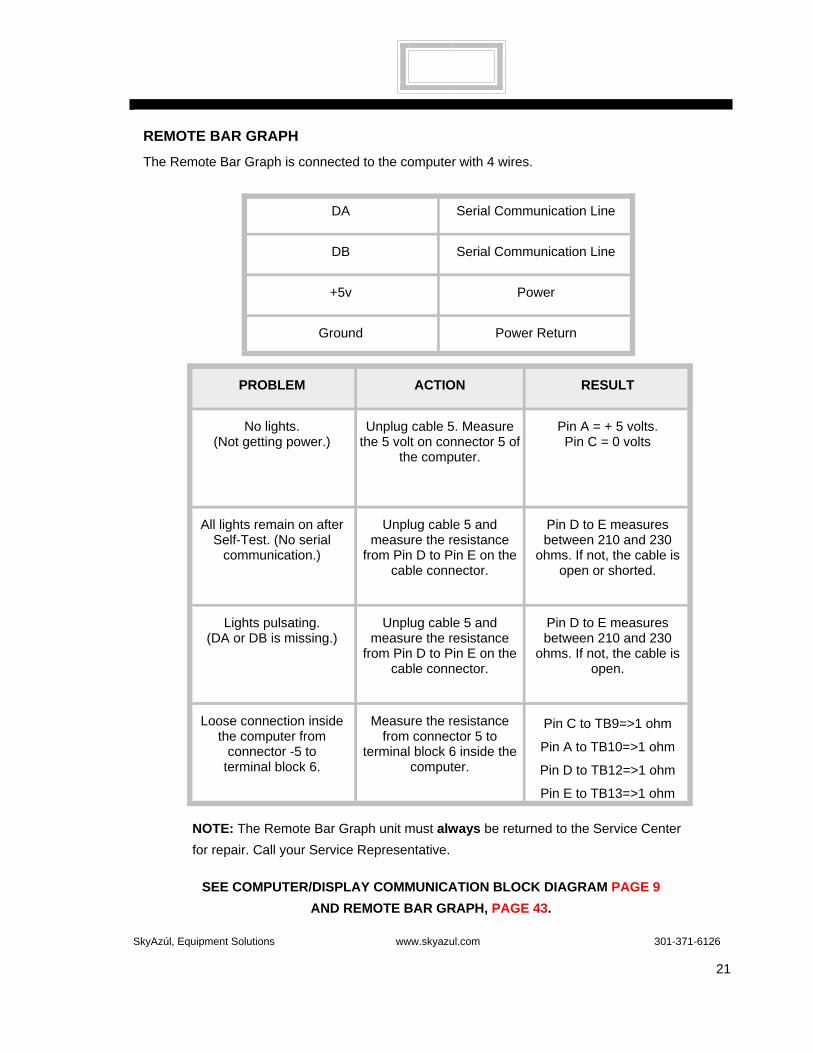
REMOTE BAR GRAPH
The Remote Bar Graph is connected to the computer with 4 wires.
PROBLEM ACTION RESULT
No lights. (Not getting power.)
Unplug cable 5. Measure the 5 volt on connector 5 of
the computer.
Pin A = + 5 volts. Pin C = 0 volts
All lights remain on after Self-Test. (No serial
communication.)
Unplug cable 5 and measure the resistance
from Pin D to Pin E on the cable connector.
Pin D to E measures between 210 and 230
ohms. If not, the cable is open or shorted.
Lights pulsating. (DA or DB is missing.)
Unplug cable 5 and measure the resistance
from Pin D to Pin E on the cable connector.
Pin D to E measures between 210 and 230
ohms. If not, the cable is open.
Loose connection inside the computer from
connector -5 to terminal block 6.
Measure the resistance from connector 5 to
terminal block 6 inside the computer.
Pin C to TB9=>1 ohm
Pin A to TB10=>1 ohm
Pin D to TB12=>1 ohm
Pin E to TB13=>1 ohm
NOTE: The Remote Bar Graph unit must always be returned to the Service Center for repair. Call your Service Representative.
DA Serial Communication Line
DB Serial Communication Line
+5v Power
Ground Power Return
SEE COMPUTER/DISPLAY COMMUNICATION BLOCK DIAGRAM PAGE 9 AND REMOTE BAR GRAPH, PAGE 43.

SkyAzúl, Equipment Solutions www.skyazul.com 301-371-6126
22
THIS PAGE SHOULD BE BLANK.

SkyAzúl, Equipment Solutions www.skyazul.com 301-371-6126
23
Section III
SYSTEM INSTALLATIONS ....................................................................................23
SELECTING THE RIGHT SYSTEM INSTALLATION ILLUSTRATION..................... 24
SYSTEM LAYOUTS WITH CORRESPONDING SERIAL NUMBER PREFIX..........25
1. SYSTEM INSTALLATION E1.......................................................................................25
2. SYSTEM INSTALLATION D3, E9, F1, F2, & F3...........................................................26

SkyAzúl, Equipment Solutions www.skyazul.com 301-371-6126
24
SELECTING THE RIGHT SYSTEM INSTALLATION ILLUSTRATION
The information in this section is meant to familiarize the user with the major components and System setup for most models of the MicroGuard® 434 System.
To locate the correct illustration for your needs, match the first two digits of the serial number of your crane to the serial number prefix in column 1 of the following table. Column 2 will identify the appropriate illustration for your needs in the following pages.
Serial No. Prefix System Installation
E1 1
D3 2
E9 2
F1 2
F2 2
F3 2
FIGURE 3.0 CRANE SERIAL NUMBERS WITH CORRESPONDING ILLUSTRATION NUMBERS.

SkyAzúl, Equipment Solutions www.skyazul.com 301-371-6126
25
1. SYSTEM INSTALLATION
Cranes with Serial Number Prefix E1
SYSTEM LAYOUTS WITH CORRESPONDING SERIAL NUMBER PREFIX
Computer Unit
Connector 8
Connector 7
Connector 6
Connector 5
Connector 3
Connector 2
Connector 1
Extension Drum & Angle Sensor
Anti-Two BlockSwitch
(Main Boom)
Anti-Two BlockSwitch
(Attachment)
Display Console
Bargraph Display (Optional)
Cable 3
Cable 2
Cable 1
Cable 5
Cable 6
Cable 7
Cable 8
Pressure Transducer(Rod Side)
Pressure Transducer(Piston Side)
Swing PotConnection(Inside Collector Column)
Power / Motion DisconnectConnection
OPERATOR CAB
UPPER STRUCTURE(Mounted behind seat in Cab)
BOOMATTACHMENT
Reel-Off Cable toBoom Head
Mounted at Boom Head
Mounted on attachment Head

SkyAzúl, Equipment Solutions www.skyazul.com 301-371-6126
26
2. SYSTEM INSTALLATION
Cranes with Serial Number Prefix D3, E9, F1, F2, & F3
SYSTEM LAYOUTS WITH CORRESPONDING SERIAL NUMBER PREFIX CONTINUED
Computer Unit
Connector 8
Connector 7
Connector 6
Connector 3
Connector 2
Connector 1
Extension Drum & Angle Sensor
Anti-Two BlockSwitch
Anti-Two BlockSwitch
Display Console
Cable 3
Cable 2
Cable 1
Cable 6
Cable 7
Cable 8
Pressure Transducer(Rod Side)
Pressure Transducer(Piston Side)
Swing PotConnection(Inside Collector Column)
Power / Motion DisconnectConnection
OPERATOR CAB
UPPER STRUCTURE(Mounted at rear of Cab)
BOOMATTACHMENT
Reel-Off Cable toBoom Head
Mounted at Boom Head
Mounted on attachment Head
Batt +
Connector 5
Bargraph Display (Optional)Cable 5
Ground Strap toSuperstructure
ALARM

SkyAzúl, Equipment Solutions www.skyazul.com 301-371-6126
27
Section IV
SYSTEM COMPONENTS AND ASSOCIATED FUNCTIONS .........................................31
THE COMPUTER UNIT ...............................................................................................................32
COMPUTER UNIT COMPONENTS..........................................................................................32
ACCESSING THE COMPUTER BOARD AND THE TERMINATION BOARD.........................34
CHECKING THE COMPUTER UNIT ........................................................................................34
CONNECTORS ..................................................................................................................34
UNIT COVER......................................................................................................................34
COMPUTER BOARD ASSEMBLY .....................................................................................34
COMPUTER BOX WIRING/TERMINATION BOARD ASSEMBLY....................................34
WIRE LENGTH.............................................................................................................34
INSULATION REMOVAL .............................................................................................35
FUSES ................................................................................................................................35
TESTING THE COMPUTER UNIT POWER SUPPLY VOLTAGES.........................................35
INPUT VOLTAGE ...............................................................................................................35
INTERNAL POWER SUPPLY VOLTAGE ..........................................................................35
MEASURING THE ANALOG SENSOR DRIVE VOLTAGE ...............................................36
REMOVING AND INSTALLING THE COMPUTER ASSEMBLIES ..........................................37
COMPUTER BOARD REMOVAL.......................................................................................37
COMPUTER BOARD INSTALLATION...............................................................................37
TERMINATION BOARD AND BOX REMOVAL .................................................................38
TERMINATION BOARD AND BOX INSTALLATION .........................................................38
COMPUTER CHIPS .....................................................................................................................38
PROGRAM ROM CHIP.............................................................................................................38
PERSONALITY ROM CHIP ......................................................................................................38
DUTY ROM CHIP......................................................................................................................39
COMPUTER CHIP REMOVAL AND INSTALLATION ..............................................................39
SkyAzúl, Equipment Solutions www.skyazul.com 301-371-6126
28
COMPUTER CHIP REMOVAL ......................................................................................... 39
COMPUTER CHIP INSTALLATION................................................................................. 39
OPERATOR’S DISPLAY CONSOLE...................................................................................... 40
DISPLAY CONSOLE MODELS .............................................................................................. 40
CHECKING THE OPERATOR’S DISPLAY CONSOLE.......................................................... 41
READING THE (LIQUID CRYSTAL) DISPLAYS ............................................................. 41
BUTTONS THAT DON’T RESPOND ............................................................................... 41
CONNECTORS ................................................................................................................ 41
HORN ............................................................................................................................... 42
MOISTURE....................................................................................................................... 42
OPERATOR’S DISPLAY CONSOLE REMOVAL AND INSTALLATION................................ 42
REMOVAL OF HORIZONTAL AND VERTICAL FLUSH MOUNT CONSOLES .............. 42
INSTALLATION OF HORIZONTAL AND VERTICAL FLUSH MOUNT CONSOLES ...... 42
REMOVAL OF HORIZONTAL BRACKET MOUNT CONSOLES .................................... 42
INSTALLATION OF HORIZONTAL BRACKET MOUNT CONSOLES ............................ 42
REMOTE BAR GRAPH ............................................................................................................. 43
CHECKING THE REMOTE BAR GRAPH ............................................................................. 43
LAMPS.............................................................................................................................. 44
BRIGHTNESS CONTROL................................................................................................ 44
VIEWING DIFFICULTIES ................................................................................................. 44
CABLE AND CONNECTOR ............................................................................................. 44
MOISTURE....................................................................................................................... 44
REMOTE BAR GRAPH REMOVAL AND INSTALLATION..................................................... 45
REMOVAL OF A REMOTE BAR GRAPH............................................................................... 45
INSTALLATION OF A REMOTE BAR GRAPH....................................................................... 45
SkyAzúl, Equipment Solutions www.skyazul.com 301-371-6126
29
EXTENSION REEL ...................................................................................................................... 46
CHECKING/TESTING EXTENSION REEL FUNCTIONS........................................................ 47
CHECKING THE VOLTAGE OF THE BOOM EXTENSION SENSOR .................................... 48
CHECKING THE VOLTAGE OF THE BOOM ANGLE SENSOR............................................. 50
ANTI-TWO BLOCK FUNCTION ............................................................................................... 52
EXTENSION REEL PARTS REMOVAL AND INSTALLATION................................................ 52
ANGLE SENSOR REMOVAL .......................................................................................... 52
ANGLE SENSOR INSTALLATION .................................................................................... 53
EXTENSION REEL REMOVAL.......................................................................................... 53
EXTENSION REEL INSTALLATION ................................................................................. 53
PRESSURE SENSOR................................................................................................................. 54
PRESSURE CHANNEL FAULT GUIDE................................................................................... 55
FUNCTIONAL TESTS........................................................................................................ 55
SENSOR RESISTANCE MEASUREMENT....................................................................... 57
PISTON PRESSURE SENSOR......................................................................................... 57
ROD PRESSURE SENSOR .............................................................................................. 58
PRESSURE SENSOR REMOVAL AND INSTALLATION........................................................ 59
ANTI-TWO BLOCK FUNCTION ................................................................................................ 59
LOGIC LEVELS ........................................................................................................................ 59
POWER, MOTION DISCONNECT & BOOM MODE FUNCTIONS ..................................... 62
REPLACEABLE PARTS........................................................................................................... 63
SWING SENSOR ......................................................................................................................... 64
SWING POTENTIOMETER...................................................................................................... 64
AIN 5 AND AIN 6 ...................................................................................................................... 64
CHECKING THE SWING POTENTIOMETER ......................................................................... 64

SkyAzúl, Equipment Solutions www.skyazul.com 301-371-6126
30
THIS PAGE SHOULD BE BLANK.

SkyAzúl, Equipment Solutions www.skyazul.com 301-371-6126
31
Section IV
SYSTEM COMPONENTS AND ASSOCIATED FUNCTIONS
This section provides detailed information on the MicroGuard®434 System components and associated functions.
System components include the Computer Unit, Operator’s Display Console, Remote Bar Graph, Extension Reel, and Pressure Sensor. Functions include the Anti-Two Block Function, the Power, Motion Disconnect, and Boom Mode Functions, and the Swing Sensor. Possible problems are outlined in this section as well as methods for testing, checking, and replacing System components.
SkyAzúl, Equipment Solutions www.skyazul.com 301-371-6126
32
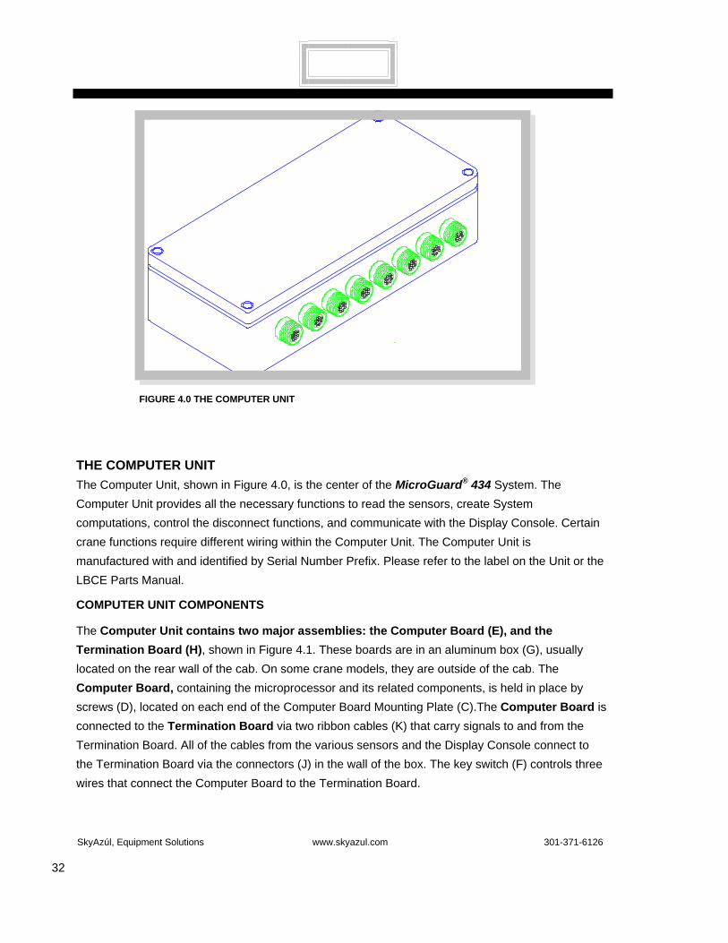
FIGURE 4.0 THE COMPUTER UNIT
THE COMPUTER UNIT The Computer Unit, shown in Figure 4.0, is the center of the MicroGuard® 434 System. The Computer Unit provides all the necessary functions to read the sensors, create System computations, control the disconnect functions, and communicate with the Display Console. Certain crane functions require different wiring within the Computer Unit. The Computer Unit is manufactured with and identified by Serial Number Prefix. Please refer to the label on the Unit or the LBCE Parts Manual.
COMPUTER UNIT COMPONENTS
The Computer Unit contains two major assemblies: the Computer Board (E), and the Termination Board (H), shown in Figure 4.1. These boards are in an aluminum box (G), usually located on the rear wall of the cab. On some crane models, they are outside of the cab. The Computer Board, containing the microprocessor and its related components, is held in place by screws (D), located on each end of the Computer Board Mounting Plate (C).The Computer Board is connected to the Termination Board via two ribbon cables (K) that carry signals to and from the Termination Board. All of the cables from the various sensors and the Display Console connect to the Termination Board via the connectors (J) in the wall of the box. The key switch (F) controls three wires that connect the Computer Board to the Termination Board.

SkyAzúl, Equipment Solutions www.skyazul.com 301-371-6126
33
FIGURE 4.1 COMPUTER UNIT COMPONENTS
FIGURE 4.2 COMPUTER BOX AND LAYOUT OF THE TERMINATION BOARD
0V0V-DR
AIN6AIN5+DR
0V-DR
AIN4AIN3AIN2
0V-DR
AIN1AIN0+DR
+DR
TX1-TX1+-DR+DR0VTX0-TX0+-DR+DR
0V0V0V0V+VP+VP+VP+VP
ATBINDIN15DIN14DIN13DIN12DIN11DIN10DIN9DIN8DIN7
DIN5DIN4DIN3DIN2DIN1
DIN6
DOUT0DOUT1DOUT2DOUT3DOUT4DOUT5DOUT6DOUT70V+5VA+5VBDADBRES0VATBOUT
NOC
NCNO
C
NOC
NC+CL-CL
NC
RELA
Y 2
RELA
Y 1
SPAR
E
-B+B+B+B
A2BBOARD
RL1OVERLOAD
RL2ATB
SPARERELAY
(BOOM MODE)
+B
FS2
FS1
B+ GND +VP +5V RES+15V-15V
TB1
TB2
TB3
TB4
TB5 TB6TB7

SkyAzúl, Equipment Solutions www.skyazul.com 301-371-6126
34
ACCESSING THE COMPUTER BOARD AND THE TERMINATION BOARD
1. Refer to Figure 4.1. To access the Computer Board, remove the four screws (B) that secure the cover (A) to the Computer Box. Carefully remove the lid from the Computer Box. Set the lid and the four screws aside.
2. To access the Termination Board (H), remove the screws (D) located at each end of the Computer Board Mounting Plate. Swing the plate up and out of the way.
Warning: Ensure that the electrical components do not contact the aluminum box or the cab walls. This is especially important if the power is left on for test purposeS.
3. Take care not to damage the ribbon cables. If the Computer Board must be removed from the Computer Box, refer to COMPUTER BOARD REMOVAL, page 37.
4. Figure 4.2 shows the Computer Box and the layout of the Termination Board.
CHECKING THE COMPUTER UNIT
When operated for extended periods of time, under extreme conditions, the computer can become damaged and that damage may or may not be apparent. The following sections identify areas in the computer unit that should be checked for prevention and/or repair of possible problems
• Connectors
There are up to 8 connectors on the computer box. These connectors control all of the signals and power distribution within the System. The pins and sockets within the connector halves can become damaged or a pin may be bent, broken, or ‘pushed back’ inside the housing.
• Unit Cover
The computer unit cover must be secured carefully to prevent water or dust from entering the computer unit. A very small amount of water inside the housing could cause the System to malfunction or fail completely. This is quite possible when the vehicle is pressure-washed on a regular basis.
• Computer Board Assembly
The Computer Board has a number of parts that are plugged into sockets. The parts that are most prone to incorrect insertion are the four largest IC chips: IC2, IC3, IC7, & IC4. The pins on these devices are very easily bent and may not be connecting to the socket underneath. Carefully inspect the board under a good light, looking down at the space between each chip and its socket to detect a bent pin.
• Computer Box Wiring/Termination Board Assembly
Cable ends must conform to the following requirements and must be carefully inserted.
◊ Wire Length: Measure wire length carefully. Wires that are too long get trapped or pinched when the Termination Board Assembly is replaced or when
SkyAzúl, Equipment Solutions www.skyazul.com 301-371-6126
35
the Computer box is closed. Wires that are too short could break internally, when under tension.
Insulation Removal: Remove Insulation around wires before clamping them in the terminal block. With too little exposed wire, the Terminal Block could attach to the insulation rather than the conductor. Too much exposed wire may mean that a short-circuit could occur between adjacent conductors.
Warning: Ensure that all of the strands of a stripped wire are inside the Terminal Block. Loose strands of wire sometimes short to adjacent Terminal Blocks or even to other cables.
• Fuses
Two fuses, on the Termination Board, protect the equipment during abnormal or extreme conditions. Fuse failure is usually due to excessive current.
TESTING THE COMPUTER UNIT
POWER SUPPLY VOLTAGES
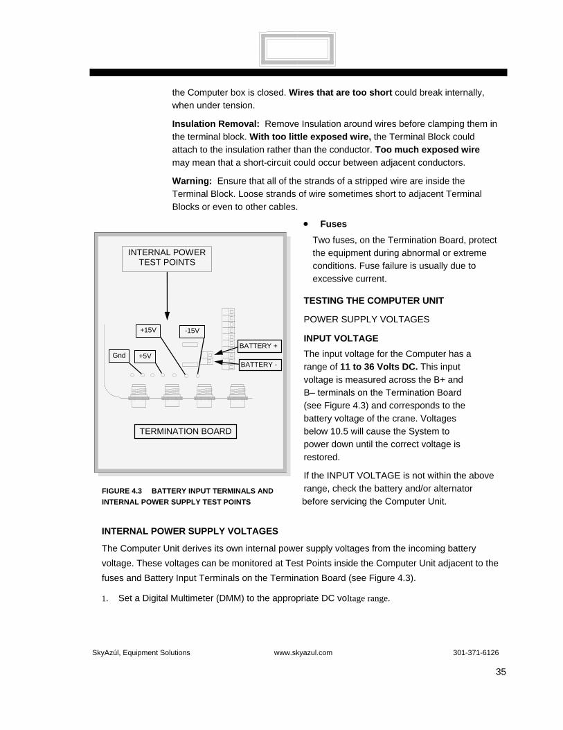
INPUT VOLTAGE The input voltage for the Computer has a range of 11 to 36 Volts DC. This input voltage is measured across the B+ and B– terminals on the Termination Board (see Figure 4.3) and corresponds to the battery voltage of the crane. Voltages below 10.5 will cause the System to power down until the correct voltage is restored.
If the INPUT VOLTAGE is not within the above range, check the battery and/or alternator before servicing the Computer Unit.
INTERNAL POWER SUPPLY VOLTAGES
The Computer Unit derives its own internal power supply voltages from the incoming battery voltage. These voltages can be monitored at Test Points inside the Computer Unit adjacent to the fuses and Battery Input Terminals on the Termination Board (see Figure 4.3).
1. Set a Digital Multimeter (DMM) to the appropriate DC voltage range.
INTERNAL POWER TEST POINTS
TERMINATION BOARD
BATTERY -
BATTERY +Gnd +5V
+15V -15V
FIGURE 4.3 BATTERY INPUT TERMINALS AND INTERNAL POWER SUPPLY TEST POINTS

SkyAzúl, Equipment Solutions www.skyazul.com 301-371-6126
36
2. Turn on the power. 3. Connect the negative lead to the GND Test Point.
4. Place the positive lead in each of the following test points:
• +5V Test Point [+4.90V ~ +5.10V]
• +15V Test Point [+14.90V ~ +15.10V]
• -15V Test Point [-14.90V ~ -15.10V]
The above voltages indicated for each point are in the acceptable range. If any of these voltage points are out of range, it may be necessary to replace the Computer Box. Before replacing the Computer Box, please call for support. Refer to “Where to Go for Help,” page 4.
MEASURING THE ANALOG SENSOR DRIVE VOLTAGE
Analog Sensor Drive Voltages are measured at the Analog Input Group Terminals on the Termination Board in the Computer Unit. The drive voltage for all analog sensors is measured between any +DR and –DR in the Analog Input group. Refer to Figure 4.4. The voltage should read 5.25 ± 0.1 Volts.
1. Set a Digital Multimeter (DMM) to an appropriate DC voltage range.
2. Turn on the power.
3. Place the black (negative) lead on any –DR (–Drive) and the red (positive) lead on any +DR (+Drive) terminal.
4. The voltage should be 5.25 ± 0.1 Volts.
5. If the Analog Drive Voltage is not within this range, shut off the power, and disconnect all of the external sensor cables including the pressure sensors, cables 1-5.
6. Recheck the Analog Drive Voltage. If the voltage is still out of range, the Computer Board will need to be replaced. If the voltage is within range, reconnect each cable, one at a time, checking the Analog Drive Voltage after each cable is connected.
7. If, after reconnecting any one of the sensor cables, the Analog Drive Voltage goes out of range, the wiring to the sensor is probably grounded or the sensor itself is faulty.
8. Check all wiring and the sensor itself. Repair the faulty wiring or replace the defective sensor.
FIGURE 4.4 MEASURING THE ANALOG SENSOR DRIVE VOLTAGE
0V0V-DR
AIN6AIN5+DR
0V-DR
AIN4AIN3AIN2
0V-DR
AIN1AIN0+DR
+DR
TX1-TX1+-DR+DR0VTX0-TX0+-DR+DR
0V0V0V0V+VP+VP+VP+VP
Drive Voltage5.25V +/-0.1V
The analog drive voltage maybe measured between any+DR & -DR terminal.
TB2
TB3
TB4

SkyAzúl, Equipment Solutions www.skyazul.com 301-371-6126
37
REMOVING AND INSTALLING THE COMPUTER ASSEMBLIES The Computer Board Assembly and the Termination Board and Box Assembly may be replaced, if necessary. Step-by-step instructions for this procedure are outlined below.
COMPUTER BOARD REMOVAL
1. Turn off the power. Remove the cover of the Computer Unit to access the Computer Board. See Accessing the Computer Board and the Termination Board, page 34.
2. Release the two screws located at opposite ends of the Computer Board Mounting Plate. Carefully swing the Computer Board Mounting Plate up and out of the way.
3. Disconnect both ribbon cables at the Termination Board connectors by pushing the locking tabs outwards. The connectors will automatically eject.
4. Disconnect the following three wires that connect the key switch on the Computer Board Mounting Plate to the Termination Board (see Figure 4.2).
• Red Wire > Relay 1 ‘C’ Terminal Block TB7, PIN 7
• Black Wire > Relay 1 ‘NO’ Terminal Block TB7, PIN 8
• Yellow Wire > DIN10 Terminal Block TB5, PIN 10
5. Remove the Computer Board Assembly with attached ribbon cables.
6. Carefully remove the necessary computer chips ( IC 2, 3, & 7) from the defective Computer Board.
COMPUTER BOARD INSTALLATION
1. Immediately transfer the computer chips ( IC 2, 3, & 7) from the defective Computer Board to the new Computer Board Assembly. Refer to Computer Chip Installation, page 39.
2. Ensure that the ribbon cables on the Computer Board are fully engaged and locked. Refer to Termination Board and Box Installation, page 38.
3 Position the new Computer Assembly above the computer box and reconnect the key switch wires to the correct terminals of the Termination Board (see Step 4 above).
4. Reconnect the two ribbon cables to the Termination Board. Ensure the connectors are fully engaged and locked.
5. Insert and tighten the two screws that secure the Computer Board to the Mounting Plate. Ensure that the ribbon cables are not trapped or pinched and are away from the edge of the box when installing the cover.
OFF
ON
FIGURE 4.5 CALIBRATION
SWITCH IN OFF
POSITION
CAL.

SkyAzúl, Equipment Solutions www.skyazul.com 301-371-6126
38
6. Ensure that the ‘CALIBRATION ENABLED/DISABLED’ switch is set at the ‘DISABLED’ position. Refer to Figures 4.5 and 4.6.
7. Install the Computer Box cover.
TERMINATION BOARD AND BOX REMOVAL
1. Remove the Computer Board. See Computer Board Removal, page 37.
2. Disconnect all cable connectors from the Computer Box.
3. Remove the four screws securing the Computer Box.
4. Remove the Computer Box.
Note: The Termination Board must always be replaced with the Aluminum Box due to the wiring looms between the board assembly.
TERMINATION BOARD AND BOX INSTALLATION
1. Install the new Computer Box, securing it with the four mounting screws.
2. Follow the steps in Computer Board Installation, page 37-38, Numbers 2-7.
3. Reconnect all other cables to appropriate connectors.
Note: Connectors 1 and 2 are SIMILAR. These connectors are color-coded. Ensure that the color on the connecting cable matches the color on the socket.
COMPUTER CHIPS
The computer Unit contains three replaceable computer chips identified below and illustrated in Figure 4.6 on the next page. For any computer chip replacement, follow directions in Computer Chip Removal and Installation, page 39.
The Computer Chips include:
The Program ROM Chip, identified as IC2 on the Computer Board, includes information specific to the System and contains the main program data needed for the computer to function. Installation of the Program ROM Chip does NOT necessitate recalibration of the System.
The Personality ROM Chip, identified as IC7 on the Computer Board, contains calibration data unique to each crane. The Personality ROM Chip must correspond to the prefix serial number on the crane. Installation of the Personality ROM Chip does not necessitate recalibration of the System, if the new Personality ROM Chip is an exact duplicate of the original. If a copy of the Personality ROM Chip is not available, the System will need to be completely recalibrated.

SkyAzúl, Equipment Solutions www.skyazul.com 301-371-6126
39
Calibration Switch
The Duty ROM Chip, identified as IC3 on the Computer Board, contains a copy of the Load Chart which MUST MATCH the Load Chart in the crane. Installation of the Duty ROM Chip does NOT necessitate recalibration of the System.
COMPUTER CHIP REMOVAL AND INSTALLATION
Warning: When removing and installing chips, ensure that the power is off. Do not touch the chip pins unless you are properly grounded. Static electricity can damage chips. Warning: Before removing or installing computer chips, refer to Computer Chips, page 38.
COMPUTER CHIP REMOVAL 1. Turn the power off.
2. Refer to Figure 4.6 above. Remove chip from Computer Board with a chip removal tool. Note: Chip removal and installation tools can be obtained from any electronics store. COMPUTER CHIP INSTALLATION
1. Following package instructions, use the installation tool to insert new chip into socket.
2. Ensure that the notch in the chip lines up with the notch in the socket.
3. Ensure that all pins are properly inserted into the chip socket. These pins are very easily bent.
Warning: Failure to have all pins inserted properly into the chip socket can cause damage to the System and the chip.
FIGURE 4.6 THE MAIN COMPUTER BOARD
IC4 Ram
SkyAzúl, Equipment Solutions www.skyazul.com 301-371-6126
40
FIGURE 4.7: OPERATOR DISPLAY CONSOLE
OPERATOR DISPLAY CONSOLE
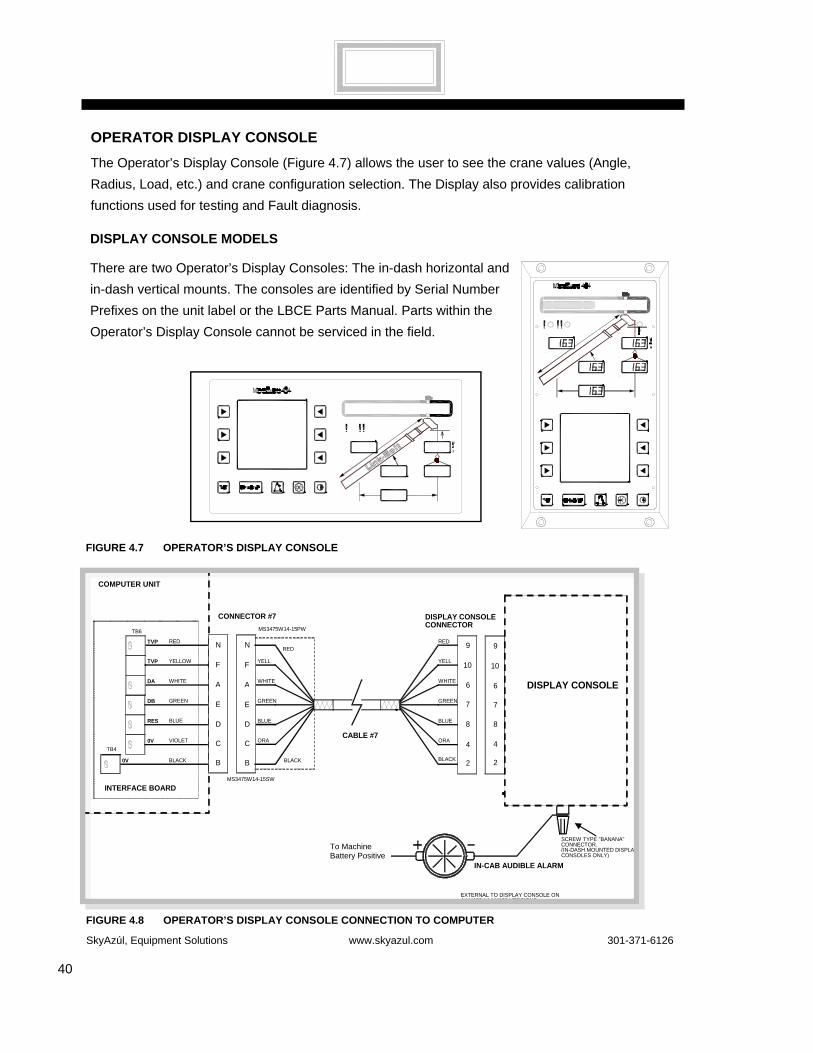
The Operator’s Display Console (Figure 4.7) allows the user to see the crane values (Angle, Radius, Load, etc.) and crane configuration selection. The Display also provides calibration functions used for testing and Fault diagnosis.
DISPLAY CONSOLE MODELS
There are two Operator’s Display Consoles: The in-dash horizontal and in-dash vertical mounts. The consoles are identified by Serial Number Prefixes on the unit label or the LBCE Parts Manual. Parts within the Operator’s Display Console cannot be serviced in the field.
FIGURE 4.8 OPERATOR’S DISPLAY CONSOLE CONNECTION TO COMPUTER
FIGURE 4.7 OPERATOR’S DISPLAY CONSOLE
BLACK
ORA
YELL
GREEN
WHITE
9
10
2
4
6
DISPLAY CONSOLE CONNECTOR
TB6
INTERFACE BOARD
CABLE #7
YELL
BLACK
ORA
WHITE
GREEN 7
8
RED
BLUE
9
10
2
4
6
7
8
DISPLAY CONSOLE
N
F
A
E
D
C
B
RED
BLUE
N
F
A
E
D
C
B
COMPUTER UNIT
YELLOW
BLACK
VIOLET
WHITE
GREEN
RED
BLUE
MS3475W14-15PW
MS3475W14-15SW
TVP
0V
0V
DA
DB
TVP
RES
CONNECTOR #7
TB4
TO MACHINE BATTERY POSITIVE IN-CAB AUDIBLE ALARM
EXTERNAL TO DISPLAY CONSOLE ON A444106 / A444108 VERSIONS.
SCREW TYPE "BANANA" CONNECTOR. (IN-DASH MOUNTED DISPLAY CONSOLES ONLY)
To Machine Battery Positive

SkyAzúl, Equipment Solutions www.skyazul.com 301-371-6126
41
CHECKING THE OPERATOR’S DISPLAY CONSOLE
The Operator’s Display Console is normally very reliable. However, when operated for extended periods, under extreme conditions, the Console can become damaged. The damage is not always apparent. To help identify subtle faults that are sometimes difficult to find, or that may be attributed, mistakenly, to other kinds of problems, please review the following comments.
READING THE (LIQUID CRYSTAL) DISPLAYS
Always adjust the Display contrast first. On bracket-mounted models only, reposition the Display Console slightly. The most commonly encountered problem is caused by reflections.
Note: It may not be possible to correct this problem completely, especially on flush-mounted Display Consoles exposed to bright sunlight. If the problem concerns the contents of one or more of the Display Screens, refer to the Problem Finder Flow Charts in this Manual.
BUTTONS THAT DON’T RESPOND
All button options are not available for use at all times. Ensure that the non-responsive button is programmed to respond at that point in the operation of the System. Press the button in the center. Pressing the printed symbol ‘at one end’ may not activate the switch underneath. Buttons that are damaged or have a surface that is worn may cause the switch underneath to operate improperly. In this case, refer to Operator’s Display Console Removal and Installation, page 42.
CONNECTORS
A single circular connector, common to all Display Models, is positioned on the rear of the Display Console. On the bracket-mounted style, it is clearly visible on the rear of the housing. On the flush-mounted versions, it is ‘hidden’ behind the panel, within the dash assembly. This connector carries power and signals from the Computer Unit to the Display Console. Examine this connector carefully. It is possible for the pins and sockets within the connector halves to bend, break, or ‘be pushed back’ inside the housing.
• On flush-mounted Display Consoles (vertical model), one additional connection, besides the circular connector, is required: The Horn Drive Wire is a single black lead that should be attached to the black terminal on the rear of the Display Console housing.
SkyAzúl, Equipment Solutions www.skyazul.com 301-371-6126
42
HORN
On bracket-mounted Display Consoles, the Horn is inside at the rear of the housing. On flush-mounted Consoles, the Horn is outside the housing. If there is a problem with the horn, ensure that the Horn Drive Wire is connected correctly to the black terminal on the rear of the Display Console housing. Release the Display from its connections and pull the Display gently forward. If the wire is intact and connected correctly and the horn is still not operating correctly, the horn may need to be replaced. If possible, test the horn operation by temporarily installing another horn known to operate correctly.
MOISTURE
The Display Consoles (both bracket and flush-mounted designs) offer adequate protection against dust and water, when correctly installed. However, they are unlikely to fully protect the sensitive electronic assemblies inside against pressure-washing or heavy rainfall. In this case, replace the Console, especially if moisture is visible behind the Display ‘windows.’
OPERATOR DISPLAY CONSOLE REMOVAL AND INSTALLATION
REMOVAL OF HORIZONTAL AND VERTICAL FLUSH MOUNT CONSOLES
1. Remove and set aside the four mounting screws on the defective Operator’s Display Console.
2. Disconnect the cable and ground wire from the connector on the rear of the defective Operator’s Display Console.
INSTALLATION OF HORIZONTAL AND VERTICAL FLUSH MOUNT CONSOLES
1. Attach the electrical cable to the electrical connector on the new Console.
2. Attach the new Operator’s Display Console to the cab with the four mounting screws.
REMOVAL OF HORIZONTAL BRACKET MOUNT CONSOLES
1. Disconnect the electrical cable from the electrical connector on the rear of the Operator’s Display Console.
2. Remove the defective Operator’s Display Console from the bracket in the cab by removing the knob on each side of the Console. Retain the knobs for future use.
INSTALLATION OF HORIZONTAL BRACKET MOUNT CONSOLES
1. Install the new Operator’s Display Console on the bracket in the cab by positioning it between the bracket legs and inserting and tightening the knob on each side of the Operator’s Display Console.
continued on next page
SkyAzúl, Equipment Solutions www.skyazul.com 301-371-6126
43
2. Connect the electrical cable to the electrical connector on the rear of the Operator’s Display
Console. Refer to Figure 4.8.
REMOTE BAR GRAPH
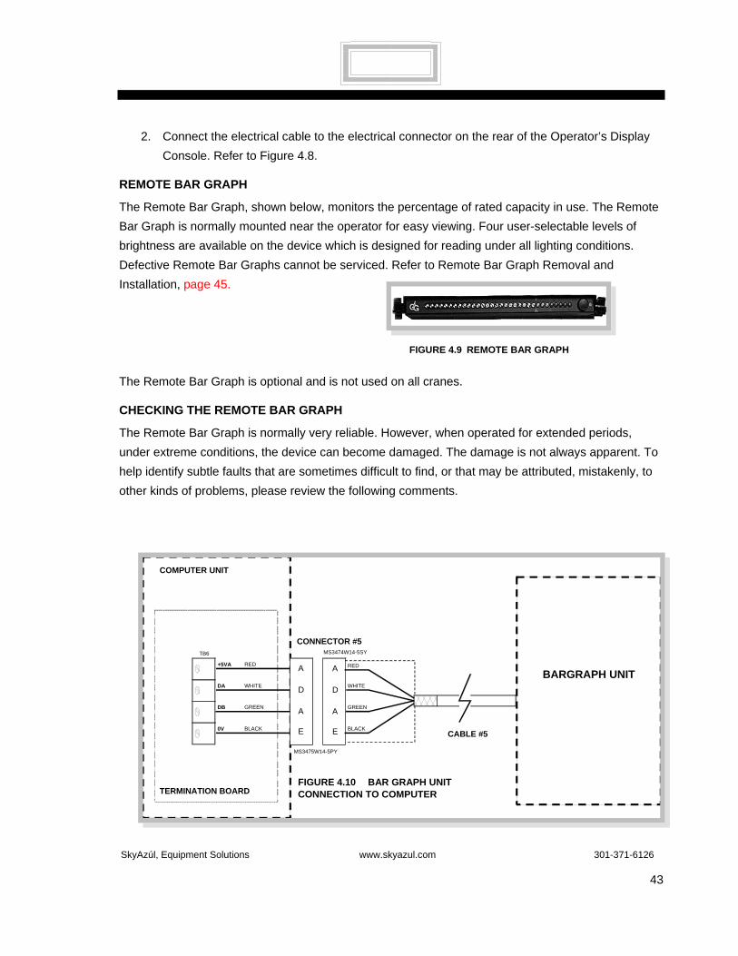
The Remote Bar Graph, shown below, monitors the percentage of rated capacity in use. The Remote Bar Graph is normally mounted near the operator for easy viewing. Four user-selectable levels of brightness are available on the device which is designed for reading under all lighting conditions. Defective Remote Bar Graphs cannot be serviced. Refer to Remote Bar Graph Removal and Installation, page 45.
The Remote Bar Graph is optional and is not used on all cranes.
CHECKING THE REMOTE BAR GRAPH
The Remote Bar Graph is normally very reliable. However, when operated for extended periods, under extreme conditions, the device can become damaged. The damage is not always apparent. To help identify subtle faults that are sometimes difficult to find, or that may be attributed, mistakenly, to other kinds of problems, please review the following comments.
TB6
TERMINATION BOARD
CABLE #5BLACK
GREEN
BARGRAPH UNITA
A
D
E
RED
WHITE
A
A
D
E
COMPUTER UNIT
BLACK
GREEN
RED
WHITE
MS3474W14-5SY
MS3475W14-5PY
0V
DB
+5VA
DA
CONNECTOR #5
FIGURE 4.9 REMOTE BAR GRAPH
FIGURE 4.10 BAR GRAPH UNIT CONNECTION TO COMPUTER
SkyAzúl, Equipment Solutions www.skyazul.com 301-371-6126
44
LAMPS
The ‘lamps’ are Light Emitting Diodes (LED’s). They are more reliable than standard incandescent bulbs and consume far less power. LED operation can be checked at any time by the operator using the ‘Lamp Test’ feature. Always replace the entire Bar Graph Unit, if it is found to be faulty.
With the System powered, there should always be at least one (GREEN) LED lighted – the one furthest from the Brightness Control push-button, even when there is no load suspended. The Remote Bar Graph LED's should ‘track’ or ‘echo’ the Bar Graph on the Operator’s Display Console at all times.
BRIGHTNESS CONTROL
BRIGHTNESS CONTROL
Brightness Selection: There are four levels of brightness. Holding the Brightness Control button continuously will cause the Unit to automatically ‘cycle’ through the available levels. Release the button at any time to select the desired setting. Alternately pressing and releasing the button will cause the cycle to progress through the four levels in sequence. It is not possible to ‘switch-off’ the LED’s using this control.
The currently selected brightness level is not stored within the MicroGuard® System when the power is switched off. Therefore, the brightness desired will have to be set again manually when the System is next used. The Remote Bar Graph always starts with the LED’s set to MAXIMUM brightness.
VIEWING DIFFICULTIES
Always adjust the LED Brightness first. Then, reposition the Remote Bar Graph slightly. The most commonly encountered problem with this type of Display is that of reflective light. It may not be possible to correct this problem completely, especially with Units exposed to bright sunlight.
CABLE AND CONNECTOR
The Remote Bar Graph uses a single cable to communicate with the Computer Unit and to carry power. The cable is nonremovable and is a fixed length. Excess cable should be stored (not discarded) when the Unit is installed. Extending this cable is not recommended.
There is a single connector on the far end of this cable. This connector carries power and various signals between the Computer Unit and the Remote Bar Graph. Because of the nature of connectors, it is possible for the pins and sockets within the connector halves to be damaged. A pin may be bent, broken, or ‘pushed back’ inside the housing.
MOISTURE
The Remote Bar Graph offers adequate protection against dust and water when correctly installed. It is not possible, however, to fully protect the sensitive electronic assembly inside against pressure-washing or heavy rainfall. If this occurs, the Remote Bar Graph should be replaced.

SkyAzúl, Equipment Solutions www.skyazul.com 301-371-6126
45
REMOTE BAR GRAPH REMOVAL AND INSTALLATION REMOVAL OF A REMOTE BAR GRAPH
1. Turn off the power.
2. Disconnect the Remote Bar Graph cable from the Computer Box.
3. Remove the Remote Bar Graph from its bracket by loosening and removing the knob at each end of the Remote Bar Graph. Retain the knobs for reuse.
INSTALLATION OF A REMOTE BAR GRAPH
1. Put the new Remote Bar Graph in position. Reconnect and tighten the two knobs.
2. Route the cable to the computer box and connect the cable. Store excess cable line.
3. Turn on the power and ensure that the Remote Bar Graph operates correctly.

SkyAzúl, Equipment Solutions www.skyazul.com 301-371-6126
46
THE EXTENSION REEL The primary operation of the Extension Reel is to measure the extension of the telescoping sections of the boom. The Extension Reel includes an Anti-Two Block function that provides an electrical path for transmission of a signal to the Computer Unit. The Computer transmits this signal to the Operator’s Display Console warning the operator of an impending Two Block problem.
The Extension Reel includes the Anti-Two Block Function that warns of a developing Two Block condition and houses the Boom Angle Sensor, which provides the angle of the load relative to the horizon.

SkyAzúl, Equipment Solutions www.skyazul.com 301-371-6126
47
CHECKING/TESTING THE EXTENSION REEL FUNCTIONS
To check or test the following:
• Boom Extension Sensor – See Checking the Voltage of the Boom Extension Sensor, page 48.
• Boom Angle Sensor – See Checking the Voltage of the Boom Angle Sensor, page 50.
• Anti-Two Block Function – See Anti-Two Block Function, page 52.

SkyAzúl, Equipment Solutions www.skyazul.com 301-371-6126
48
CHECKING THE VOLTAGE OF THE BOOM EXTENSION SENSOR
To check or test an Extension Sensor, check the voltage. Follow the steps outlined below:
1. Fully retract the boom.
2. Access the Termination Board (see Figure 4.12). Measure the Analog Sensor Drive Voltage. Refer to page 36, Figure 4.4.
3. With a Digital Multimeter (DMM) set to read DC voltage, place the negative lead on any 0 Volt terminal of the Analog Input group.
4. Place the positive lead of the meter on the AIN2 terminal of the Analog Input group. The voltage should be 0.1 Volts.
5. Extend the boom as far as is safe to do so. The boom need not be horizontal for this test.
6. The voltage should be less than 4.9 Volts when the boom is fully extended. NOTE: During extension, the voltage should increase linearly. During retraction, the voltage should decrease linearly. If the voltage is out of range remove the four screws securing the cover on the Extension Reel Assembly (located on the left side of the main boom section) and remove.
7. Under the cover on the right side of the Extension Reel, locate the terminal strip (see Figure 4.11). This terminal strip has six wires connected to the bottom screws.
8. With a Digital Multimeter set to read DC Voltage, place the negative lead on the terminal with the blue wire (- DRive) and the positive lead on the terminal with the red wire (+DRive).
9. The voltage should be 5.25 ± 0.1 Volts. If this voltage is out of range and the Analog Drive Voltage measured in the computer is within range, the cable may be open between the Computer Unit and the Extension Reel Assembly. Check all connections and plugs between these two components. Repair or replace, as required.
10. With the negative lead of the multimeter connected to the terminal with the white wire (–DRive) and the positive lead of the multimeter connected to the terminal with the blue wire (extension signal), the voltage should be the same as the voltage measured at AIN2 of the Analog Input group in the Computer Unit. If this voltage is not the same, the cable between the Extension Reel Assembly and the Computer Unit may be faulty.

SkyAzúl, Equipment Solutions www.skyazul.com 301-371-6126
49
FIG
UR
E 4.
11
TE
RM
INA
L ST
RIP
VO
LTA
GES
TE
RM
INA
L ST
RIP
W
IRE
C
ON
NEC
TOR
1 +D
R
5.
25 v
olts
R
ed
N
2 –D
R
0
volts
W
hite
D
3 A
IN2
L
engt
h B
lue
E
4 A
IN3
A
ngle
G
reen
A
5 A
TBIN
N
orm
. - 0
vol
ts
Bro
wn
G
6 0
volts
0
volts
Bl
ack
B
EXTE
NSI
ON
REE
L

SkyAzúl, Equipment Solutions www.skyazul.com 301-371-6126
50
CHECKING THE VOLTAGE OF THE BOOM ANGLE SENSOR
Follow the steps below to check the voltage of the boom.
1. Using an inclinometer for verification, place the main boom at a zero degree angle.
2. Access the Termination Board (see Figure 4.12). Measure the Analog Drive Voltage. Refer to page 36, Figure 4.4.
3. With a Digital Multimeter set for DC Volts, connect the negative lead of the meter to any 0 Volt terminal of the Analog Input group.
4. Connect the positive lead to the AIN3 terminal of the Analog Input group.
5. With the boom horizontal, the voltage should be 0.4 ± 0.1 Volts [0.3V ~ 0.5V is within range].
6. Raise the main boom to a 60 degree angle. Verify that it is at a 60 degree angle with an inclinometer.
7. With the boom at a 60 degree angle, the voltage should be 3.02 ± 0.1 Volts [2.92V ~ 3.12V is within range]. If voltage is out of range, return boom to the horizontal position. Remove the cover from the Extension Reel on the left side of the main boom.
8. Locate the terminal strip (see Figure 4.11) on the right side of the Extension Reel. This terminal strip has six wires connected to the bottom screws.
9. With a Digital Multimeter set to read DC Voltage, place the negative lead on the terminal with the white wire (–DRive) and the positive lead on the terminal with the red wire (+DRive).
10. The voltage should be 5.25 ± 0.1 Volts. If this voltage is out of range and the Analog Drive Voltage checked in step 2 was within range, the Extension Reel cable may be open between the Computer Unit and the Extension Reel Assembly. Check all connections between these two components. Repair or replace as required.
11. With the negative lead of the multimeter connected to white, (–DRive) and the positive lead of the multimeter connected to green, (Angle Signal), the voltage should be the same as the voltage measured at AIN3 of the Analog Input group in the computer. If this voltage is not the same, the cable between the reel and the computer or the boom angle sensor

SkyAzúl, Equipment Solutions www.skyazul.com 301-371-6126
51
FIGURE 4.12 TERMINATION BOARD
FIGURE 4.13 EXTENSION REEL TERMINAL STRIP
RED +DR
BLUE -DR
GREEN ANGLE SIGNAL TO AIN3
AIN2 - LENGTH - WHITE WIRE
0V0V-DR
AIN6AIN5+DR
0V-DR
AIN4AIN3AIN2
0V-DR
AIN1AIN0+DR
+DR
TX1-TX1+-DR+DR0VTX0-TX0+-DR+DR
AIN3, Voltage varieswith Boom angle.0.4V at 0 deg.3.02V at 60 deg.
Drive Voltage
TB2
TB3
TB4
Ain2 voltage varies with Boom length

SkyAzúl, Equipment Solutions www.skyazul.com 301-371-6126
52
may be faulty.
ANTI-TWO BLOCK FUNCTION
The Anti-Two Block Function is a safety function that signals an impending collision between the hook block or ball and head sheaves. When the distance between these points is within an acceptable range, there is a zero voltage reading. As distance changes to a dangerous zone, a voltage registers and releases a warning and/or a danger alert. Refer to Anti-Two Block Function, page 59.
EXTENSION REEL PARTS REMOVAL AND INSTALLATION
When all tests have been completed, and it has been determined that parts must be replaced rather than repaired, locate the appropriate section below and follow the steps, as directed.
ANGLE SENSOR REMOVAL
1. Refer to Figure 4.11. Access the Angle Sensor by removing the cover from the Extension Reel Assembly.
2. Disconnect the three wire leads at the terminal block from the Angle Sensor.
3. Loosen the cable clamps so the Angle Sensor cable can be removed from the triangle plate.
4. Remove the Angle Sensor from the Extension Reel Assembly by removing the two mounting nuts and washers.

SkyAzúl, Equipment Solutions www.skyazul.com 301-371-6126
53
ANGLE SENSOR INSTALLATION
1. Install the new Angle Sensor and secure it loosely with the two mounting nuts and washers. See Figure 4.11.
2. Secure the Angle Sensor cable to the triangle plate with the three cable clamps.
3. Install the three wire leads from the Angle Sensor to the terminal block.
4. Raise the boom to a 60 degree angle, and verify the angle with an inclinometer. While viewing the Display, position the Angle Sensor until the Display reads 60 degrees. Tighten the mounting nuts.
5. Place the boom in horizontal position, and verify that it is at zero degrees with an inclinometer.
6. Verify that the displayed boom angle is reading zero degrees ±0.5 degrees.
7. Replace the cover on the Extension Reel Assembly.
EXTENSION REEL REMOVAL
1. Fully retract the main boom.
2. Disconnect the cable for the Two Block switch, and release the cable from the boom head anchor.
3. Without letting the cable retract too rapidly, allow the cable to retract onto the Reel.
4. Disconnect the electrical cable from the plug on the Extension Reel Assembly.
5. Remove the Extension Reel Assembly. Retain the mounting hardware for reuse.
EXTENSION REEL INSTALLATION
1. Install the new Extension Reel Assembly and secure it with the mounting hardware. Remove the cover.
2. Reconnect the electrical cable to the plug on the Extension Reel Assembly.
3. Remove the shipping cable clamp from the new cable. Slowly rewind the cable onto the Reel to avoid tension. Continue to rewind the Reel in the same direction until the distance between the boom head and the connector is approximately 12 ft.
4. Pull the cable out, passing it through the cable guides, until the end of the cable is 3 ft. beyond the boom head.
5. Wrap the cable, a minimum of five times, around the boom head anchor, and secure the line with a wire tie or the shipping cable clamp.
SkyAzúl, Equipment Solutions www.skyazul.com 301-371-6126
54
6. Reconnect the cable to the Two Block switch.
7. Manually turn the large gear connected to the potentiometer fully counter-clockwise.
8. Observe the display that shows boom length. Turn the large gear at least 3 clicks clockwise until the length on the Display shows the retracted boom length.
9. Replace and secure the Extension Reel Cover.
10. Extend and retract the main boom. Ensure that the boom length reading on the Display is correct.
PRESSURE SENSOR
The Pressure Sensor (Figure 4.14) is based around a strong metal diaphragm, which, when subjected to hydraulic pressure, bends in a predictable and repeatable way. This diaphragm is totally enclosed within the body of the sensor. The body provides strong mechanical and environmental protection for the sensitive measuring elements within. The body cavity is filled with resin to prevent moisture penetration. A fixed cable line exits from the rear end of the sensor body.
The Pressure Sensor has four electrical connections (Figure 4.15). These connections transmit power and information via the cable line to the Termination Board within the Computer Box. Two of the connections provide power (or ‘Drive’) for the strain gauge to operate. The other two carry the signal representing the amount of hydraulic pressure being measured by the sensor.
There are two Pressure Sensors installed on a MicroGuard® 434 System. One is fitted to the Piston side of the Boom Hoist Cylinders; the other to the Rod side. The Sensor on the Piston side is subject to the hydraulic pressure necessary to support the weight of the Boom, any attachments, and the Load. The other Sensor monitors the pressure necessary to control the position of the Boom. The Computer Unit uses this information (along with that from other sensors such as Extension Length and Angle) to compute the weight of the suspended load.
(Continued on page 55)
PRESSURE SENSOR
MS3475W14-5PZ
FIGURE 4.14 PRESSURE SENSOR
A B
C
E
D
“B” TO “E” 350Ω +/- 10Ω
“D” TO “C” 350Ω =+/- 10Ω
PRESSURE SENSOR CONNECTOR MS3475W14-5PZ
FIGURE 4.15 PRESSURE SENSOR CONNECTOR

SkyAzúl, Equipment Solutions www.skyazul.com 301-371-6126
55
The maximum continuous working pressure for these devices is 250 Bar (3625 psi).
There are no user-serviceable parts within the Pressure Sensor. A defective unit should be replaced. Refer to Pressure Sensor Removal and Installation, page 59.
PRESSURE CHANNEL FAULT GUIDE
A fault in a pressure sensor can cause an apparent fault in the other channel. It is necessary, therefore, to test both channels and both sensors together in order to determine which sensor is at fault.
FUNCTIONAL TESTS
PRESSURE CHANNEL FAULT GUIDE FUNCTIONAL TEST
1. Boom down all the way ensuring that the boom hoist cylinders are fully retracted. Switch off the engine.
2. Loosen the pressure sensor fittings to ensure that no pressure remains.
3. Turn on the power (not the engine).
4. Refer to FIGURE 27, page 74. Press and hold the CRANE SETUP BUTTON (CS) and the TEST BUTTON (T) on the OPERATOR’S DISPLAY CONSOLE. The GRAPHICS DISPLAY (GD) will request the SECURITY ENTRY CODE.
5. To enter the SECURITY CODE, press the TOP LEFT ARROW followed immediately by the
FIGURE 4.16 PRESSURE SENSOR CONNECTION TO THE COMPUTER
BLUE-DR D
BLUE
TX0+YELLOW
BYELLOW
RED+DR C
RED
TX0-GREEN
EGREEN
PISTONCABLE 1
CONNECTOR 1
BLUE-DR D
BLUE
YELLOWB
YELLOW
RED+DR C
RED
GREENE
GREENTX1+
TX1-
RODCABLE 2
CONNECTOR 2

SkyAzúl, Equipment Solutions www.skyazul.com 301-371-6126
56
BOTTOM RIGHT ARROW. Then quickly press the BOTTOM LEFT ARROW followed by the TOP RIGHT ARROW. (Complete this sequence in 5 seconds; if not, the SECURITY CODE will have to be entered again.)
6. The GRAPHICS DISPLAY will read: “RUN.” Press the ARROW next to MENU UP or MENU DOWN in the GRAPHICS DISPLAY and scroll to Command 03 ZERO SENSOR. To continue, PRESS THE TOP LEFT ARROW.
7. The SELECTION BOX should read ZERO TX.0 followed by 0 (ZERO) plus or minus 20. Press the TOP LEFT ARROW.
8. Press the ARROW next to MENU UP and scroll to ZERO TX.1 followed by 0 (ZERO) plus or minus 20. Press TOP LEFT ARROW to continue.
9. Retighten the fittings on the sensors.
10. Raise the boom up to a 60 degree angle.
11. Access the Zero of TX.0 described in step 7. The Display should read 200 ± 100.
12. Access the Zero of TX.1, described in step 8. The Display should read 5 ± 25.
13. Boom down. As the boom is moving down, the displayed number of TX.1 should increase.
14. Place the retracted boom at a 60 degree angle. Access the Zero of TX.0, described in step 7. Extend the boom. As the boom is extended, the displayed number of TX.0 should increase.
15. When the boom is fully extended, the Display should read 400 ± 100 for a three section boom, and 600 ± 100 for a four section boom.
16. Exit the calibration test by pressing the BOTTOM RIGHT ARROW.
The values listed are nominal values. The actual values will differ according to how the crane is equipped.
• A three section boom will show a smaller value on TX.0 under the same conditions as a four section boom.
• Additional equipment on the main boom, such as stored fly, auxiliary head sheaves, and hook blocks will give a higher value than the main boom alone.
• If any value is out of range, contact your distributor or factory service department before replacing a pressure sensor.
If the foregoing functional tests indicate faults in the pressure channels, proceed with Sensor Resistance Measurements on the next page and/or Measuring Analog Sensor Drive Voltage, on page 36.

SkyAzúl, Equipment Solutions www.skyazul.com 301-371-6126
57
SENSOR RESISTANCE MEASUREMENT
The Pressure Sensor is a balanced bridge composed of strain gauges bonded to a flexible diaphragm. The following resistance tests can be performed to establish the condition of the Pressure Sensor.
PISTON PRESSURE SENSOR
1. Turn off the computer. Disconnect the piston pressure sensor cable from connector 1 on the Computer Unit.
2. With the Digital Multimeter (DMM) set to the Ohms range, measure the resistance between pins “C” an “D” of connector MS3475W14-5PZ (see Figure 4.17). The resistance should be 350Ω± 1Ω.
3. With the DMM set to the Ohms range, measure the resistance between pins “B” an “E” of connector MS3475W14-5PZ. The resistance should be 350Ω± 10Ω.
4. With the DMM set to the Ohms range, attempt to measure the resistance in turn between pins B, C, D, E, and the case of the sensor. The DMM should indicate that an open-circuit exists in each case.
A B
C
E
D
“B” TO “E” 350Ω +/- 10Ω
“D” TO “C” 350Ω =+/- 10Ω
PRESSURE SENSOR CONNECTOR MS3475W14-5PZ
FIGURE 4.17 PRESSURE CONNECTOR

SkyAzúl, Equipment Solutions www.skyazul.com 301-371-6126
58
ROD PRESSURE SENSOR
1. Turn off the power. Disconnect the rod pressure sensor cable from connector 2 on the Computer Unit.
2. With the Digital Multimeter (DMM) set to the Ohms range, measure the resistance between pins “C” an “D” of connector MS3475W14-5PZ (see Figure 4.18). The resistance should be. 350Ω± 10Ω.
3. With the DMM set to the Ohms range, measure the resistance between pins “B” an “E” of connector MS3475Ω14-5PZ. The resistance should be 350Ω± 10Ω.
4. With the DMM set to the Ohms range, attempt to measure the resistance in turn between pins B, C, D, E, and the case of the sensor. The DMM should indicate that an open-circuit exists in each case.
FIGURE 4.18 THE PRESSURE SENSOR CONNECTED TO THE COMPUTER
BLUE-DR D
BLUE
TX0+YELLOW
BYELLOW
RED+DR C
RED
TX0-GREEN
EGREEN
PISTONCABLE 1
CONNECTOR 1
BLUE-DR D
BLUE
YELLOWB
YELLOW
RED+DR C
RED
GREENE
GREENTX1+
TX1-
RODCABLE 2
CONNECTOR 2
SkyAzúl, Equipment Solutions www.skyazul.com 301-371-6126
59
ANTI-TWO BLOCK FUNCTION LOGIC LEVELS
The signal from the Anti-Two Block (ATB) switches at the boom and fly tips is a switched ground. The ground signal is sourced in the Computer at the 0 Volt terminal of the Digital Input group.
When there is no ATB alarm, the switches at the boom head are closed, allowing the ground to be returned to the computer at the ATBIN terminal.
When there is a Two Block condition, the appropriate ATB switch will go to the open position, thereby removing the ground from ATBIN and causing ATB Alarm and Function Disconnect.
The ATB alarm and Function Disconnects are controlled separately by the ATB board in the Computer Unit.
PRESSURE SENSOR REMOVAL AND INSTALLATION PRESSURE SENSOR REMOVAL
1. We recommend that a new sensor being installed closely matches the sensitivity of the old sensor. The sensitivity value is recorded on the serial number plate (Figure 4.19).
2. Remove the connector from the faulty sensor in the computer box.
3. With the boom cylinder completely retracted in the rest position, or with the boom safely supported, remove the sensor from the boom hoist cylinder.
PRESSURE SENSOR INSTALLATION
1. Install the new sensor on the boom hoist cylinder.
2. Run the cable to the computer box and connect it to the appropriate computer box connector.
3. Pick a known weight to verify the accuracy of the system. If the load reading is not within tolerance after installing the new pressure sensor, carry out Command 6, Pressure, in the MicroGuard® 434 Calibration procedure.
FIGURE 4.19 SENSOR SERIAL NUMBER PLATE

SkyAzúl, Equipment Solutions www.skyazul.com 301-371-6126
60
The ATB board, shown on the Termination Board (Figure 4.20), operates:
• the function disconnects by controlling the coil of RL2, ATB relay, at DOUT 1.
• the audible alarm and on-screen message by controlling the logic level at DIN13.
The logic levels are as follows:
NO ALARM ATB ALARM
ATB SWITCH CLOSED OPEN
ATB IN LOW 0.2 VOLT HIGH 5 VOLT
DOUT 1 LOW 0.2 VOLT HIGH 5 VOLT
DIN 13 HIGH 12 VOLT LOW 0.2 VOLT
DOUT1
ATBIN
ATB BOARD
RL2 A2B
RL1 LOAD
DIN13
DOUT1 CONTROLS THE A2B RELAY RL2 NO A2B = LOW, 0.2VOLT ALARM = HIGH, 5VOLT
DIN13 CONTROLS THE AUBIBLE ALARM AND ON SCREEN MESSAGE. NO A2B = HIGH 12VOLT ALARM = LOW 0.2VOLT
ATBIN NO A2B =LOW O.2VOLT ALARM = HIGH 5VOLT
0V
FIGURE 4.21 TERMINATION BOARD
FIGURE 4.20 LOGIC LEVELS

SkyAzúl, Equipment Solutions www.skyazul.com 301-371-6126
61
FIGURE 4.22 ANTI-TWO BLOCK FUNCTION
2 BLOCK SWITCH AT JIB HEAD
2 BLOCK SWITCH AT MAIN BOOM HEAD
2 BLOCK SWITCH

SkyAzúl, Equipment Solutions www.skyazul.com 301-371-6126
62
POWER, MOTION DISCONNECT, & BOOM MODE FUNCTIONS
The Power and Function Disconnect wiring provides the MicroGuard® System with battery power from the machine breaker and machine motion disconnect functions controlled by the computer unit.
Some computer versions also provide a Boom Mode output which controls telescoping modes A & B of the machine.
Note: Some models may not use a power cable but have the connector on the wire harness.
FIGURE 4.23 TABLE SHOWING BOOM MODES
SEE THE SYSTEM DIAGRAM ON THE INSIDE BACK COVER FOR A TYPICAL MOTION DISCONNECT CIRCUIT.
MODEL BOOM MODE
D3 A/B
E1 A/B
E9 A/B
F1 A/B
F2 A/B
F3 MAIN BOOM + MANUAL
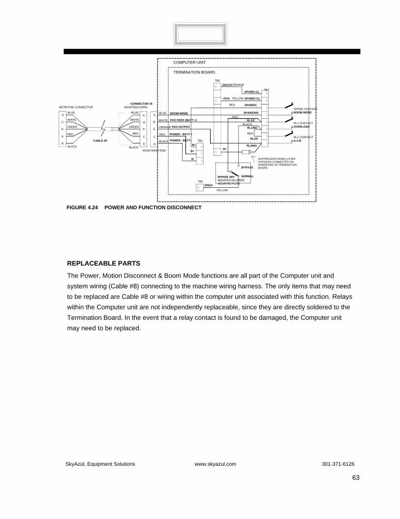
SkyAzúl, Equipment Solutions www.skyazul.com 301-371-6126
63
REPLACEABLE PARTS
The Power, Motion Disconnect & Boom Mode functions are all part of the Computer unit and system wiring (Cable #8) connecting to the machine wiring harness. The only items that may need to be replaced are Cable #8 or wiring within the computer unit associated with this function. Relays within the Computer unit are not independently replaceable, since they are directly soldered to the Termination Board. In the event that a relay contact is found to be damaged, the Computer unit may need to be replaced.
FIGURE 4.24 POWER AND FUNCTION DISCONNECT
GREEN
BLUE
WHITE
BLACK
RED
B
E
A
C
D D
C
A
E
B WHITE
ORANGE
RED
BLACK
FKO FEED (BATT +)
FKO OUTPUT
POWER - BATT +
POWER - BATT -
CONNECTOR #8MS3475W14-5PW
MS3474W14-5SW
TB1
B+
B-
TB7SPARE/-CL
SPARE/+CL
SPARE/C
RL1/C
RL1/NO
RL2/C
RL2/NOB+
SPARE/NO
0V
TB6
DIN10TB5
BYPASS KEYMOUNTED ON UPPERMOUNTING PLATE
BYPASS
NORMAL
RL1 CONTACTOVERLOAD
RL2 CONTACTA-2-B
TERMINATION BOARD
CABLE #8
SUPPRESSOR DIODE(LATER VERSIONS CONNECTED ONUNDERSIDE OF TERMINATION BOARD)
WHITE
GREEN
BLUE
RED
BLACK
RED
BLACK
YELLOW
SPARE CONTACTBOOM MODE
COMPUTER UNIT
DOUT4
+5VA YELLOW
RED
ORANGE
BLUE
RED
BOOM MODE
C
D
E
A
B
METRI-PAK CONNECTOR
SUPPRESSOR DIODE (LATER VERSIONS CONNECTED ON UNDERSIDE OF TERMINATION BOARD.

SkyAzúl, Equipment Solutions www.skyazul.com 301-371-6126
64
SWING SENSOR SWING POTENTIOMETER
AIN5 AND AIN6
It is necessary to determine the position of the upper structure of the crane in relation to the base of the crane, known as the carrier. The swing potentiometer provides this signal.
CHECKING THE SWING POTENTIOMETER
1. Access the Termination Board (see Figure 4.25). Check the Analog Drive Voltage. Refer to Measuring Analog Sensor Drive Voltage, page 36.
2. With a Digital Multimeter (DMM) set for DC Volts, check the voltage at the connections to the potentiometer located on the Anti-Two Block Board (see Figure 4.26). A red wire is attached to Connection 1; a black wire is attached to Connection 3.
3. Connect the black (negative) lead of the DMM to Connection 3 with the black wire and the red (positive) lead of the DMM to connection 1 with the red wire. The voltage should be 4.125 ± 0.1 Volts (4.025V ~ 4.225V is within range). If the voltage is out of range, the Termination Board may need to be replaced.
4. With the black lead on any 0 Volt terminal, check the voltage at AIN5 terminal and AIN6 terminal. The voltage should be 4.50V ± 0.1 maximum and 0.365V ± 0.1V minimum. Both of these voltages should rise and fall linearly within this range as the upper is rotated left or right. If the Drive Voltage and the Voltage at the connection to the potentiometer were correct, and the voltages on AIN5 and AIN6 are out of range, the Swing Potentiometer will need to replaced.
Contact your distributor or your Factory Service Department for procedures on replacing the swing potentiometer.

SkyAzúl, Equipment Solutions www.skyazul.com 301-371-6126
65
1
4 2
3
Voltage measured between 2 and 4 = 5.25 Volts.
Voltage measured between 1 and 3 = 4.125 Volts.
FIGURE 4.26 ANTI-TWO BLOCK BOARD
FIGURE 4.25 SWING POT CONNECTIONS
0V0V-DR
AIN6AIN5+DR
0V-DR
AIN4AIN3AIN2
0V-DR
AIN1AIN0+DR
+DR
TX1-TX1+-DR+DR0VTX0-TX0+-DR+DR
0V0V0V0V+VP+VP+VP+VP
AIN5 & AIN6, Voltage varieswith rotation of the upper structure.4.2V maximum, 0.36V minimumwhen the upper structure is rotating.
Drive Voltage
TB2
TB3
TB4
SkyAzúl, Equipment Solutions www.skyazul.com 301-371-6126
66
SECTION V
FAULT CODES
FAULT REPORTING AND FAULT CODES ............................................................................67
FAULT DIAGNOSTIC PROCEDURES .............................................................................67
FINDING AND UNDERSTANDING FAULT CODES...............................................................68

SkyAzúl, Equipment Solutions www.skyazul.com 301-371-6126
67
FAULT REPORTING AND FAULT CODES
System Fault Codes provide one of the most important ways to quickly locate and assess problems in the MicroGuard®System. Please review this section carefully.
FAULT DIAGNOSTIC PROCEDURES
Each time the System is turned on, it goes through a self-testing process lasting two to three seconds that automatically detects any Faults in the System. During normal operation, a Self-Test can be initiated at any time by pressing the TEST button on the Display Console.
Fault conditions in external sensors are detected without a System Self-Test.
Faults detected in the System during Self-Test, are indicated on the Display Console in the following way:
• The RED LAMP will illuminate and the AUDIBLE ALARM will sound.
Diagnosis of a Fault is obtained by PRESSING and HOLDING the TEST button. The System will then go through a Self-Test followed by the appearance of a Fault Code screen. The Fault Code screen will remain visible as long as the TEST button is pressed. Information will be displayed on the screen in the four groups shown in Figure 5.0. Note: Always repair Analog Sensor Faults (AAA) prior to investigating other faults. A complete listing of all possible Fault Codes and the description of each is listed on the following pages.
000 NO FAULTS
001 TX.0 PISTON PRESSURE SENSOR
002 TX.1 ROD PRESSURE SENSOR
004 AIN2 EXTENSION SENSOR
008 AIN3 BOOM ANGLE SENSOR
016 AIN4 S’STRUCTURE ANGLE SENSOR
032 AIN5 SWING POTENTIOMETER “A”
064 AIN6 SWING POTENTIOMETER “B”
Group AAA Analog Sensors
0 NO FAULTS
1 1 DIGITAL INPUT AND OUTPUT
2 2 ANALOG INPUT AND OUTPUT
4 4 DISPLAY UNIT
GROUP B IO FAULTS
00 NO FAULTS
01 1 PROGRAM ROM
02 2 DUTY ROM
04 4 SCRATCHPAD RAM
08 8 PERSONALITY ROM
GROUP CC MEMORY FAULTS
00 NO FAULTS
01 1 NO DUTY FOUND
02 2 CURRENT DUTY BAD
GROUP DD GENERAL FAULTS
FIGURE 5.0 FAULT CODES

SkyAzúl, Equipment Solutions www.skyazul.com 301-371-6126
68
FINDING AND UNDERSTANDING FAULT CODE(S) A Display Console window, shown below, shows how the various Fault Codes will be exhibited. The following tables have been created to simplify the identification of Faults detected by the Computer. Some Faults involve a combination of Code Numbers, indicating that there may be more than one problem or that a single problem is affecting other operations. Each Fault Code Number has been identified in the following pages on the left side of the tables and described in the column to the right.
For Example: If Code Number 009 appears in the Fault Code window, the Operator would check the table below under 009 in the left column. To the right, the Operator would see the description as Faults 001 and 008. Looking again in the left column, we see that 001 indicates a Piston Pressure Sensor problem and 008 indicates a Boom Angle Sensor problem. Read the sections relating to these operations in Section IV of this Troubleshooting Manual and report the findings to the Service Representative.
000 NO FAULTS DETECTED
001 PISTON PRESSURE
SENSOR
002 ROD PRESSURE SENSOR
003 FAULTS 001 & 002
004 EXTENSION SENSOR
005 FAULTS 001 & 004
AAA Fault Codes FAULT No. DESCRIPTION
006 FAULTS 002 & 004
007 FAULTS 001, 002, & 004
008 BOOM ANGLE SENSOR
009 Faults 001 & 008
010 Faults 002 & 008
011 Faults 001, 002, & 008
012 Faults 004 & 008
013 Faults 001, 004, & 008
014 Faults 002, 004, & 008
015 Faults 001, 002, 004, & 008
016 Superstructure Angle Sensor
017 Faults 001 & 016
AAA Fault Codes FAULT No. DESCRIPTION
AAA B DD CC
ØØØ Ø ØØ ØØ
FIGURE 5.1 DISPLAY CONSOLE WINDOW IDENTIFYING FAULT CODES.
Figure 5.2 AAA Analog Sensor Fault Codes Numbers 1-127

SkyAzúl, Equipment Solutions www.skyazul.com 301-371-6126
69
018 Fault 002 & 016
019 Fault 001, 002, & 016
020 Fault 004 & 016
021 Fault 001, 004, & 016
022 Fault 002, 004, & 016
023 Fault 001, 002, 004, & 016
024 Fault 008, & 016
025 Fault 001, 008, & 016
026 Fault 002, 008, & 016
027 Fault 001, 002, 008, & 016
028 Fault 004, 008, & 016
029 Fault 001, 004, 008, & 016
030 Fault 002, 004, 008, & 016
031 Fault 001, 002, 004, 008, & 016
032 Swing Pot “A”
033 Fault 001, & 032
034 Faults 002, & 032
035 Faults 001, 002, &
AAA Fault Codes continued FAULT No. DESCRIPTION
036 Faults 004 & 32
037 Faults 001, 004, & 032
038 Faults 002, 004, & 032
039 Faults 001, 002, 004, & 032
040 Faults 008, & 032
041 Faults 001 008, & 032
042 Faults 002, 008, & 032
043 Faults 001, 002, 008, & 032
044 Faults 004, 008, & 032
045 Faults 001, 004, 008, & 032
046 Faults 002, 004, 008, & 032
047 Faults 001, 002, 004, 008, & 32
048 Faults 016 & 032
049 Faults 001, 016, & 032
050 Faults 002, 016, & 032
051 Faults 001, 002, 016, & 032
052 Faults 004, 016, &
AAA Fault Codes FAULT No. DESCRIPTION
Figure 5.2 AAA Analog Sensor Fault Codes Numbers 1-127 continued

SkyAzúl, Equipment Solutions www.skyazul.com 301-371-6126
70
053 Faults 001, 004, 016, & 32
054 Faults 002, 004, 016, & 32
055 Faults 001, 002, 004, 016, & 32
056 Faults 008, 016, & 032
057 Faults 001, 008, 016, & 032
058 Faults 002, 008, 016, & 032
059 Faults 001, 002, 008, 016, & 032
060 Faults 004, 008, 016, & 032
061 Faults 001, 004, 008, 016, & 032
062 Faults 002, 004, 008, 016, & 032
063 Faults 001, 002, 004, 008, 016, & 032
064 SWING POT “B”
065 Faults 001 & 064
066 Faults 002 & 064
067 Faults 001, 002, & 064
068 Faults 004 & 064
069 Faults 001, 004, & 064
070 Faults 002, 004, & 064
071 Faults 001, 002, 004,
AAA Fault Codes continued FAULT No. DESCRIPTION
072 Faults 008, & 64
073 Faults 001, 008, & 64
074 Faults 002, 008, & 064
075 Faults 001, 002, 008, & 064
076 Faults 004, 008, & 064
077 Faults 001, 004, 008, & 064
078 Faults 002, 004, 008, & 064
079 Faults 001, 002, 004, 008, & 064
080 Faults 016 & 064
081 Faults 001, 016 & 064
082 Faults 002, 016 & 064
083 Faults 001, 002, 016 & 064
084 Faults 004, 016, & 064
085 Faults 001, 004, 016, & 064
086 Faults 002, 004, 016, & 064
087 Faults 001, 002, 004, 016, & 064
088 Faults 008, 016, & 064
089 Faults 001, 008, 016, & 064
090 Faults 002, 008, 016,
AAA Fault Codes continued FAULT No. DESCRIPTION
Figure 5.2 AAA Analog Sensor Fault Codes Numbers 1-127 continued
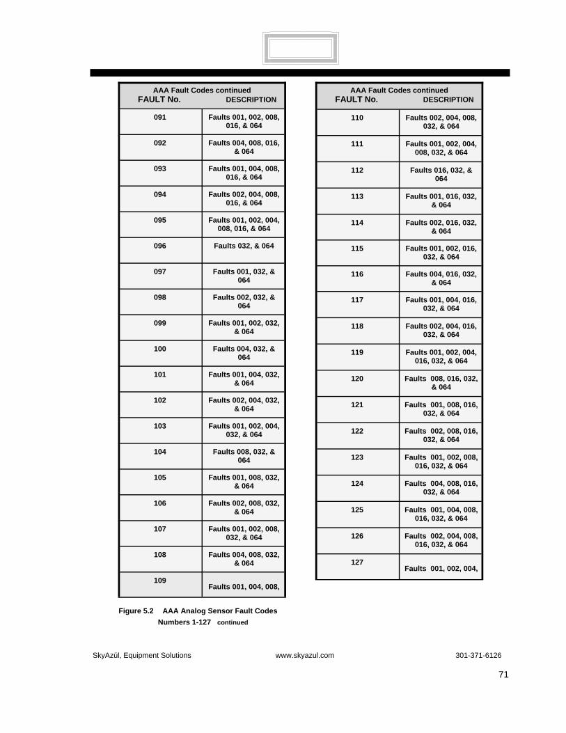
SkyAzúl, Equipment Solutions www.skyazul.com 301-371-6126
71
091 Faults 001, 002, 008, 016, & 064
092 Faults 004, 008, 016, & 064
093 Faults 001, 004, 008, 016, & 064
094 Faults 002, 004, 008, 016, & 064
095 Faults 001, 002, 004, 008, 016, & 064
096 Faults 032, & 064
097 Faults 001, 032, & 064
098 Faults 002, 032, & 064
099 Faults 001, 002, 032, & 064
100 Faults 004, 032, & 064
101 Faults 001, 004, 032, & 064
102 Faults 002, 004, 032, & 064
103 Faults 001, 002, 004, 032, & 064
104 Faults 008, 032, & 064
105 Faults 001, 008, 032, & 064
106 Faults 002, 008, 032, & 064
107 Faults 001, 002, 008, 032, & 064
108 Faults 004, 008, 032, & 064
109 Faults 001, 004, 008,
AAA Fault Codes continued FAULT No. DESCRIPTION
110 Faults 002, 004, 008, 032, & 064
111 Faults 001, 002, 004, 008, 032, & 064
112 Faults 016, 032, & 064
113 Faults 001, 016, 032, & 064
114 Faults 002, 016, 032, & 064
115 Faults 001, 002, 016, 032, & 064
116 Faults 004, 016, 032, & 064
117 Faults 001, 004, 016, 032, & 064
118 Faults 002, 004, 016, 032, & 064
119 Faults 001, 002, 004, 016, 032, & 064
120 Faults 008, 016, 032, & 064
121 Faults 001, 008, 016, 032, & 064
122 Faults 002, 008, 016, 032, & 064
123 Faults 001, 002, 008, 016, 032, & 064
124 Faults 004, 008, 016, 032, & 064
125 Faults 001, 004, 008, 016, 032, & 064
126 Faults 002, 004, 008, 016, 032, & 064
127 Faults 001, 002, 004,
AAA Fault Codes continued FAULT No. DESCRIPTION
Figure 5.2 AAA Analog Sensor Fault Codes Numbers 1-127 continued

SkyAzúl, Equipment Solutions www.skyazul.com 301-371-6126
72
0 No Faults
1 Digital Input and
2 Analog Input and Output
3 Faults 1 & 2
4 Display Unit
5 Faults 1 & 4
6 Faults 2 & 4
7 Faults 1, 2, & 4
FAULT No. DESCRIPTION
00 No Faults
01 Program ROM
02 Duty ROM
03 Faults 01 & 02
04 Scratchpad RAM
05 Faults 02 & 03
06 Faults 02 & 04
07 Faults 01, 02, & 04
08 Personality ROM
09 Faults 01, & 08
10 Faults 02 & 08
11 Faults 01, 02, & 08
12
Faults 04 & 08
13 Faults 01, 04, & 08
14 Faults 02, 04, & 08
15 Faults 01, 02, 04, &
FAULT No. DESCRIPTION
0 No Faults
01 No Duty
02 Current Duty Bad
03 Faults 01 & 02
FAULT No. DESCRIPTION
Figure 5.3 B IO Fault Codes
Figure 5.5 DD General Fault Codes
Figure 5.4 CC Memory Fault Codes

SkyAzúl, Equipment Solutions www.skyazul.com 301-371-6126
73
SYSTEM DIAGRAMS

SkyAzúl, Equipment Solutions www.skyazul.com 301-371-6126
74
SEL
MU
CS
T
B
FIGURE 27: OPERATOR’S DISPLAY CONSOLE
MD
MENU UP
MENU DOWN
SELECTION BOX
SB
B BAR GRAPH
GD GRAPHICS DISPLAY WINDOW
T TEST BUTTON
CS CRANE SETUP BUTTON
SEL APPROVE & CONTINUE/CALIBRATE
MU MENU UP
MD MENU DOWN
SB SELECTION BOX
EX EXIT
TO SCROLL TO DESIRED COMMAND shown in SELECTION BOX
GD
EXIT EX
Refer to Section IV, page 40.

SkyAzúl, Equipment Solutions www.skyazul.com 301-371-6126
75
CR
AN
E S
OLE
NO
IDS
IC2
IC3
IC7
PRO
GR
AM
DU
TY
PER
SON
ALIT
Y
DIS
PLA
Y
CO
MPU
TER
BO
AR
D
INTE
RFA
CE
BO
AR
D
EXTE
NSI
ON AN
GLE
SLIP
RIN
G
N/O
CCBO
OM
BOO
MU
PH
OIS
TEX
TEN
DD
OW
N
1k5k
BOAR
DBL
OC
KAN
TI-T
WO
+5V 1M
THE
ATB
SW
ITC
HE
S A
RE
SH
OW
NIN
TH
E N
OR
MA
L O
PE
RA
TIN
GP
OS
ITIO
N.
EMER
GE
NC
YBY
-PAS
S S
WIT
CH
DA
DB OV
.36V
AIN
6A
IN5
4.45
V
-DR
+DR
AIN
3A
IN2
ATB
IN0V
TB1-
1
TB1-
3TB
1-2
TB1-
4TB
1-5
SU
PP
LY
+/- 1
5VP
OW
ER
SU
PP
LY
+5V
PO
WE
R
220
TB3-
14TB
3-13
34
470
12
ATB
BRD
ATB
BRD+5
.25V
TB3-
4TB
3-1
TB3-
8TB
3-7
REE
LIN
G D
RU
M
CO
AX
ANTI
-TW
O B
LOC
K SW
ITC
HES
MA
IN B
OO
MJI
B
PIS
TON
350
OH
MP
RE
SS
UR
E
SW
ING
PO
T36
0 D
eg
2.5k
-8
V+8
V+5
.25V
0V+5
V
-15V
+15V
RL1
+V
RL
OU
T
DO
UT
0
+V
RL2
REM
OTE
BA
R G
RA
PH
TB7-
11
DIN
10D
OU
T 1
DIN
13
A B
1 3
N/O
TB2 TX
1+
-DR
+DR
TX1-
TB7-
10
TB7-
8
TB7-
7P
IN-B
THE
REL
AYS
AN
D B
Y-PA
SS
SWIT
CH
OPE
RA
TIN
G P
OSI
TIO
NS.
ARE
SHO
WN
IN T
HE
NO
RM
AL
RO
DP
RE
SSU
RE
350
OH
M
TB2 TX
0++D
RTX
0--D
R
B+ B-C
RAN
EBA
TTER
Y
+CL
-CL
TB7
B+
(DO
UT
4)
BO
OM
MO
DE
DIA
GR
AM
SPA
RE
REL
AY
PIN
-EC
8 C8
(+5V
)
C N/O
C N/O
C8
PIN
A
BO
OM
MO
DE
SO
LEN
OID
B-
+5V
OV
DA
DB
OV
RES
ET
+VP M
ICR
OG
UA
RD
434
SYS
TEM
DIA
GR
AM


SkyAzúl, Equipment Solutions www.skyazul.com 301-371-6126

SkyAzúl, Equipment Solutions www.skyazul.com 301-371-6126
SkyAzúl, Inc. 16 Walnut Street Middletown, MD 21769 Phone 301-371-6126 Fax 301-371-0029 [email protected] www.skyazul.com

![Z MG540 Display.ppt - SkyAzul€¦ · Microsoft PowerPoint - Z MG540 Display.ppt [Compatibility Mode] Author: SKYAZUL Main Created Date: 6/14/2016 6:03:05 PM](https://img.pdfslide.us/doc/110x75/602eb09a93169310f675679c/z-mg540-skyazul-microsoft-powerpoint-z-mg540-compatibility-mode-author-skyazul.jpg)