Embed Size (px)
Citation preview

Microgrid in Remote Communities-Technical Challenges
Mostafa Farokhabadi, Ph.D. CandidateUniversity of Waterloo
Ehsan Nasr, Ph.D.
Canadian Solar Inc.
1

Canadian Solar Inc. (CSI)
• Background
2
Top 3 PV module supplier in the world
Proven project development track record and
8.5GW project pipeline
Founded in Ontario, 2001
Listed on NASDAQ (CSIQ) in 2006
Over 7,000 employees globally
Global footprint in 90 countries
PV module supplier
PV project development
Energy storage and Microgridsolutions

Canadian Solar Global Network
More than 7,000 employees in 18 countries

CSI Microgrid Solutions
4
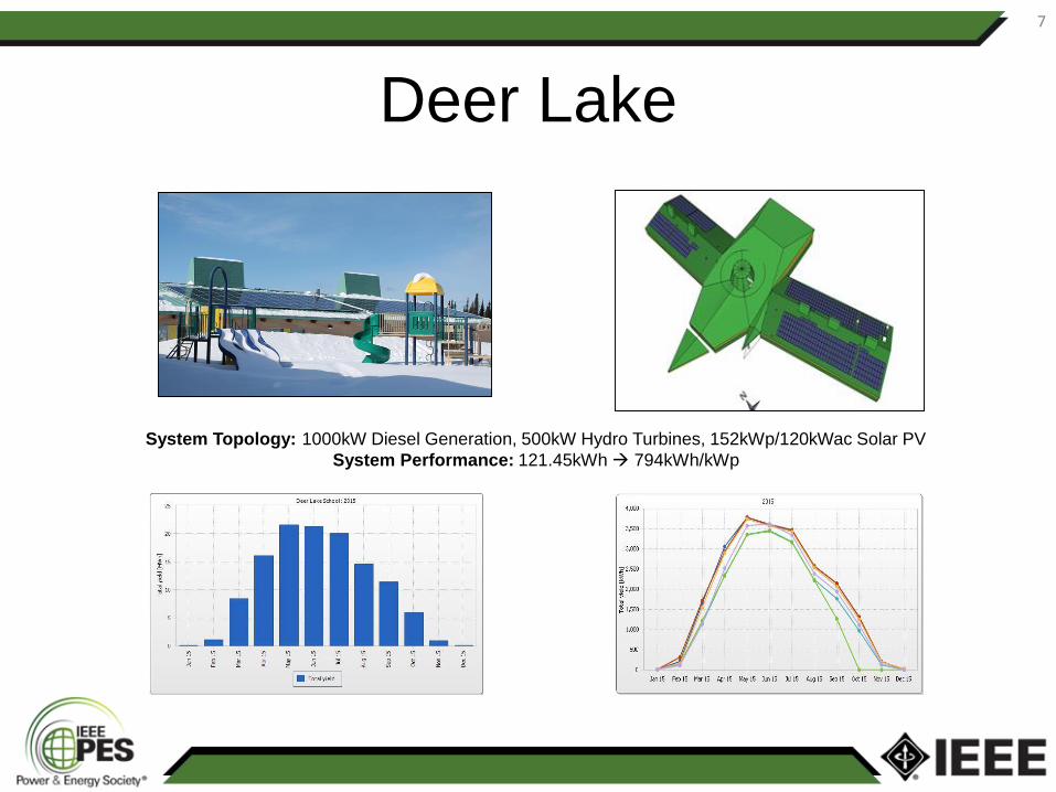
Microgrid Project Experience (Remote Communities)
5
Deer Lake
North Spirit Lake McDowell Lake
Keewaywin
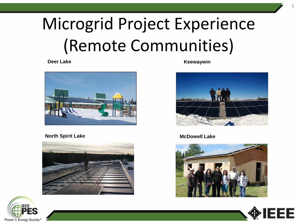
Deer Lake
6
----What did we do?
Proposed a phased-in solar capacity development plan
Phase I - Install a 152kWdc/120kWac solar rooftop system connected into the diesel generating system.
Gained confidence of community and utility that renewables would not have a negative impact.
----What will we do?
Phase II – Implement a full microgrid system with 1MW solar system and energy storage.
----What did we learn?
Installation in these
remote areas with
extreme weather is
very challenging.
Logistics via winter roads
can experience delays
and unexpected
complications.
Important to triple check
and cross check bills of
material.
Ability to adapt to
unexpected situations.
Hydro One Remotes and
most Independent Power
Authorities now see the
benefit of renewable and
are eager to do more.
----How did it start?
High dependency on
diesel generation.
Existing generation
capacity could not
meet the rising energy
demands of their
growing communities .
7 homes unconnected.
Keewaytinook
Okimakanak (KO)
approached Canadian
Solar for a solution.
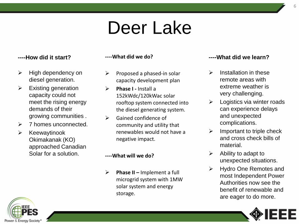
Deer Lake
7
System Topology: 1000kW Diesel Generation, 500kW Hydro Turbines, 152kWp/120kWac Solar PV
System Performance: 121.45kWh 794kWh/kWp

Deer Lake
8
Pack Everything!
Bring your own food →
Work can be Cold!
↓

Fort Severn
9
----What did we do?
Proposed a phased-in solar capacity development plan
Phase I - Installed a grid connected 24kWdc/20kWac solar rooftop system.
Gained confidence of community and utility that renewables would not have a negative impact.
Phase II – To implement a pilot microgrid including 300kW solar, 10kW wind and 200kW battery to study the impact on the grid with diesel as primary.
Phase III – To implement a full microgrid including 600kW solar, 500kW wind and 750kW battery allowing for diesel-off operation.
----What did we learned?
Logistics in remote
locations is
unpredictable.
Shipping BOS
materials was another
challenge
Important to triple check
and cross check bills of
material.
Necessity of working
with the situations as
they arrive and adapting
to a change on the fly.
----How did it start?
Most remote
community in Ontario.
Highest cost of
electricity generation
due to transport cost of
diesel fuel.
Planned community
growth.
Prior – failed –
experience with wind
energy.

Fort Severn
10

Fort Severn
11
Technical Challenges
• Ground mount PV installation in permafrost
– Ballasted racking system
• Renewable penetration levels
– Power
– Energy
• Energy storage system sizing
• Frequency stability
• Grid forming capability of Power Conversion System (PCS)
• Ride through capability of PV and battery inverter (UL 1741, IEEE 1547)
12

Battery Sizing (Dynamic Simulation)
13
Battery Requirement #1 for 300 kW PV shading
Input Output
Battery Characteristics Minimum Frequency f < 57 duration (s)
Droop rate (kW/Hz) 30
57.09 0Output Level (kW) 90
Power rate (kW/S) 210
Battery Requirement #2 for 300 kW PV disconnection
Input Output
Battery Characteristics Minimum Frequency f < 57 duration (s)
Droop rate (kW/Hz) 60
57.24 0Output Level (kW) 160
Power rate (kW/S) 580

ValidationModeling
ValidationModeling
Software Simulation – Dynamic Modeling

0 2 4 6 8 100
50
100
150
200
250
300
350
Time (s)
PV o
utpu
t (kW
)
0 2 4 6 8 1056
57
58
59
60
61
Time (s)
Freq
uenc
y (H
z)
Configuration/input Simulation output
Software Simulation – Dynamic Analysis

Frequency Stability
16
0 1 2 3 4 5 6 7 8 9 1055
56
57
58
59
60
61
62
X: 4.927
Y: 60.5
t(s)
Freq
uenc
y(H
z)
X: 6.256
Y: 60.5
X: 4.082
Y: 57
X: 2.784
Y: 57
300 kW PV shading
0 1 2 3 4 5 6 7 8 9 1056
57
58
59
60
61
62
X: 4.971
Y: 60.5
t(s)
Freq
uenc
y(H
z)
X: 6.187
Y: 60.5
X: 3.936
Y: 57
X: 2.907
Y: 57
250 kW PV shading
0 1 2 3 4 5 6 7 8 9 1056.5
57
57.5
58
58.5
59
59.5
60
60.5
61
X: 5.042
Y: 60.5
t(s)
Freq
uenc
y(Hz
)
X: 6.064
Y: 60.5
X: 3.575
Y: 57
X: 3.26
Y: 57
200 kW PV shading
0 1 2 3 4 5 6 7 8 9 1057
57.5
58
58.5
59
59.5
60
60.5
61
X: 5.165
Y: 60.5
t(s)
Freq
uenc
y(Hz
)
X: 5.856
Y: 60.5
150 kW PV shading
• System With PV Without Battery Energy Storage System (BESS)

Frequency Stability
17
• Short term (high resolution data) for a PV and BESS active power
output

Grid forming vs grid following PCS
• Virtual Synchronous generator
• Frequency/voltage droop control-voltage source inverter
• Current source inverter
18
Not every supplier in the market has grid forming capability for
Battery PCS.

Standard/ Requirement
• Hydro one interconnection requirement
• IEEE 1547/ UL 1741
• May need to expand the frequency range
19
Frequency Range (Hz) Clearing Times (s)
> 60.5 0.16
< (59.5 – 57.0) 300 (adjustable)
< 57.0 0.16
Ref: Hydro One Distributed Generation Interconnection Requirements

Conclusion
• Challenges in remote communities to
implement microgrids are different than other
microgrid applications.
• Frequency stability is of main concerns for off
grid system.
• Standard/ requirements for these applications
may need to be revisited.
• Battery energy storage system and control
system in microgrid application are not “plug and
play”, and close attention should be paid for
system stability concerns.
20

21
Thank You