Embed Size (px)
Citation preview

Microfluidic assay for simultaneous culture ofmultiple cell types on surfaces or within hydrogels
The MIT Faculty has made this article openly available. Please share how this access benefits you. Your story matters.
Citation Shin, Yoojin, Sewoon Han, Jessie S Jeon, Kyoko Yamamoto, IoannisK Zervantonakis, Ryo Sudo, Roger D Kamm, and Seok Chung.“Microfluidic Assay for Simultaneous Culture of Multiple Cell Typeson Surfaces or Within Hydrogels.” Nat Protoc 7, no. 7 (June 7, 2012):1247–1259.
As Published http://dx.doi.org/10.1038/nprot.2012.051
Publisher Nature Publishing Group
Version Author's final manuscript
Citable link http://hdl.handle.net/1721.1/87711
Terms of Use Creative Commons Attribution-Noncommercial-Share Alike
Detailed Terms http://creativecommons.org/licenses/by-nc-sa/4.0/
Microfluidic assay for simultaneous culture of multiple cell typeson surfaces or within hydrogels
Yoojin Shin1, Sewoon Han1, Jessie S. Jeon2, Kyoko Yamamoto4, Ioannis K.Zervantonakis2, Ryo Sudo4, Roger D. Kamm2,3, and Seok Chung1
1School of Mechanical Engineering, Korea University, Seoul, Korea.
2Department of Mechanical Engineering, Massachusetts Institute of Technology, Cambridge, MA,USA.
3Department of Biological Engineering, Massachusetts Institute of Technology, Cambridge, MA,USA.
4Department of System Design Engineering, Keio University, Yokohama, Japan.
Abstract
This protocol describes a simple but robust microfluidic assay combining three-dimensional (3D)
and two-dimensional (2D) cell culture. The microfluidic platform comprises hydrogel
incorporating chambers between surface-accessible microchannels. Using this platform, well-
defined biochemical and biophysical stimuli can be applied to multiple cell types interacting over
distances of <1mm, thereby replicating many aspects of the in vivo microenvironment.
Capabilities exist for time-dependent manipulation of flows and concentration gradients as well as
high-resolution real-time imaging for observing spatial-temporal single cell behavior, cell-cell
communication, cell-matrix interactions and cell population dynamics. These heterotypic cell type
assays can be used to study cell survival, proliferation, migration, morphogenesis and
differentiation under controlled conditions. Applications include the study of previously
unexplored cellular interactions, and have already provided new insights into how biochemical
and biophysical factors regulate interactions between populations of different cell types. It takes 3
days to fabricate the system and experiments can run for up to several weeks.
INTRODUCTION
Development of the protocol
Three-dimensional (3D) models of cellular microenvironments mimicking the functions of
intact tissues are recognized to have numerous advantages over well-plate based two-
dimensional (2D) cell culture approaches1. A robust in vitro assay enabling 3D cell culture
is beneficial for cell-based drug and toxicity screening to closely mimic the
Correspondence should be addressed to R.D.K. ([email protected]) and S.C. ([email protected])..
AUTHOR CONTRIBUTIONSY.S. and S.H. were equally contributed to this protocol, designing and carrying out the experiments and writing the paper. J.S.J, K.Y.,I.K.Z, R.S. and S.C. designed and carried the experiments. S.C. is responsible for all the experiments described in this article andpreparation of the paper. R.D.K. is responsible for providing guidance for the experiments and for editing the paper.
NIH Public AccessAuthor ManuscriptNat Protoc. Author manuscript; available in PMC 2014 May 27.
Published in final edited form as:Nat Protoc. ; 7(7): 1247–1259. doi:10.1038/nprot.2012.051.
NIH
-PA
Author M
anuscriptN
IH-P
A A
uthor Manuscript
NIH
-PA
Author M
anuscript

microenvironment of living tissues, and to successfully isolate and define specific
contributions of single and/or multiple factors to the overall processes of cellular
morphogenesis including cell migration, angiogenesis, and cancer metastasis2-5. Cells
cultured using traditional 2D tissue culture methods are morphologically different from cells
in 3D environments, and moreover, show different gene expression levels of a variety of
proteins2,3 compared to their native environment in vivo. Approaches that employ cells
suspended in 3D gels have also been used, but these typically lack the ability to culture in
defined locations cells of different types6. For example, Transwell® systems enable the
study of 3D chemotactic responses of the cells cultured on filters or in gels placed on the
filters, but lack the ability to image at high resolution in real time, or to control many aspects
of the local cellular microenvironments. Other 3D assays suspending cells in a gel or plating
cells on beads within a gel provide a simple and effective means for monitoring cellular
morphogenesis within an extracellular matrix (ECM)7,8. However, sprouts or migration of
cells from a solid bead differ from cellular morphogenesis in vivo. It is also difficult to
produce a well-controlled microenvironment with similar dimensions to tissue structures in
vivo.
Recognizing the need to better replicate the in vivo environment, we developed a novel
hydrogel-incorporating microfluidic cell culture assay, which facilitates the interaction of
cells in 3D ECM scaffolds, and thus, better captures the complex behaviors that occur within
the in vivo microenvironment compared to 2D in vitro assays9. Similar microfluidic
platform protocols designed for neuroscience research10, gelatin-based cellular interaction11
and bacterial chemotaxis12 have enabled integration of complex environmental factors and
high resolution in situ imaging. Our system is a multipurpose platform for local containment
of ECM-mimicking hydrogels to supply precisely controlled conditions to the cells cultured
on and/or inside. It also provides the flexibility necessary to study 3D cellular
morphogenesis13, 3D homotypic/heterotypic cell-cell and cell-ECM interactions9,14,15, and
3D responses to biochemical gradients16-18, interstitial flow15, diffusion of soluble factors,
and various mechanical stimuli19 with the same batch of cells at the same time. Furthermore,
due to the smaller length scales compared to traditional cultures it requires lower volumes of
reagents and media.
Applications of the method
The microfluidic platform described in this protocol has been widely applied to 3D cell
culture in various applications, including 3D angiogenic responses under the gradient of
growth factors introduced in the media13,16-18 or secreted by co-cultured tumor cells14. The
angiogenic structure of networks of endothelial cells in the hydrogel was confirmed as 3D
and regulated by surface treatment of the microfluidic channel13. We also found that
primary hepatocytes cultured on the hydrogel under interstitial flow formed 3D tissues,
enabling detoxification and regulating capillary morphogenesis of co-cultured endothelial
cells20. We investigated the endothelium-dependent migration of smooth muscle cells co-
cultured with ECs21, 3D axonal responses under various growth factor gradients22, and 3D
cancer metastasic processes14,23. Cancer cells invaded and migrated in 3D into the hydrogel
and finally intravasated through the endothelial monolayer cultured in a microfluidic
channel14. We modified the microfluidic design to create a more stable concentration
Shin et al. Page 2
Nat Protoc. Author manuscript; available in PMC 2014 May 27.
NIH
-PA
Author M
anuscriptN
IH-P
A A
uthor Manuscript
NIH
-PA
Author M
anuscript

gradient that was better able to represent the metabolic activity of cells18,24 and also
successfully manufactured a platform of similar design suitable for high volume
manufacture using hot-embossed plastics25. The structure, results and possible applications
of the platform technology have been described in two recent reviews9,26. In this protocol,
we describe the basic procedure for using a hydrogel-incorporating microfluidic assay using
angiogenesis studies as an example. Based on the protocol, the readers can easily integrate
conventional soft lithography technology27 to explore a wide variety of applications with
small modifications in cell seeding and culturing procedures.
Experimental design
Microfluidic systems are fabricated in PDMS using standard soft lithographic methods.
Other materials such as standard tissue culture plastics can also be used in combination with
either hot-embossing or injection molding methods. It is preferable if all features are of
uniform depth to enable simple single-stage fabrication. Drilling or coring holes through the
full thickness of the device provides direct access to the gel-containing and media channels,
and bonding a coverslip to the side with imprinted features produces closed channels. The
entire process of microfluidic cell culture including fabrication, cell culture and analysis is
explained here. From various microfluidic device designs, we chose to focus on the one
most widely used for 3D cell culture assay, which is composed of 4 gel regions and 3
channels, each of which is individually accessible (Fig.1). The cells are usually cultured in
the center channel and the other two side channels act as control channel and condition
channel, respectively. The interior of the channels is coated with ECM proteins to promote
cell adhesion. In particular, the described method of coating with Poly-D-lysine
Hydrobromide (PDL) has been confirmed to promote 3D capillary morphogenesis into the
hydrogel13. Finally, we illustrate the method for introducing a hydrogel solution (type I
collagen gel as the prototypical example) controlling gel stiffness, seeding cells inside the
gel region and immunostaining the cells after the experiment using a method that is specially
optimized for the micro-scale. In addition to general instructions we give specific details for
how to evaluate the angiogenic response to a gradient in vascular endothelial growth factor
(VEGF).
The part of the protocol describing the manufacture of the microfluidic device can be
divided into the master fabrication (photolithography; steps 1-8) and mold fabrication (soft
lithography stages). The first stage only needs to be performed once per master type, as a
master can be used multiple times in the subsequent stages. For the general biology
community, the photolithography stage may require equipment not available in the typically
stocked lab plus assistance from someone experienced in microfluidics or microfabrication.
Further details can also be acquired from other protocols (see procedure 1-712 & procedure
1-527). However, the soft lithography stage only requires equipment (vacuum desiccator and
dry oven) that is commonly available in a biology laboratory and is easier to follow without
specialist knowledge. Further details about how to perform soft lithography can be found in
other protocols (see procedure 8-1212 & procedure 6-1127).
Shin et al. Page 3
Nat Protoc. Author manuscript; available in PMC 2014 May 27.
NIH
-PA
Author M
anuscriptN
IH-P
A A
uthor Manuscript
NIH
-PA
Author M
anuscript

Limitations
Whereas the small dimensions within the device are essential for realistic cell-cell signaling
to occur, it also imposes certain inherent limitations. Typical biochemical assays could be
difficult to perform due to the small cell number (typically <1000 cells), so methods of
interrogating biological function are generally restricted to antibody staining for the
distribution, concentration or activation of various intra- or extracellular biomolecules.
Channel structure has been modified in similar devices to increase cell number to enable
conventional biochemical analysis of ELISA or RT-PCR28. Loading the system with
hydrogel, media and cells requires training, but can usually be mastered in a day. Imaging is
typically performed by conventional microscopy including confocal microscopy, but other
methods such as transmission EM are also possible.
MATERIALS
REAGENTS
Photoresist SU-8 2050 (for photolithography, Microchem) ! CAUTION Wear protective
goggles and gloves and suitable protective clothing when working with photoresist.
Photoresists developer (for photolithography, PGMEA, Microchem)
Isopropyl alcohol (for photolithography, IPA)
Sylgard 184 silicone elastomer base and curing agent (for soft lithography, Dow Corning)
Sterile 1X phosphate buffered saline (PBS), pH 7.4 (Thermo Scientific, cat. no.
SH30256.01)
Deionized water (Direct-Q® 3; water purifying system, Millipore)
Ethanol: 70% in sterile deionized water
Methanol
Poly-D-lysine (PDL) hydrobromide solution (see REAGENT SETUP) (Sigma-Aldrich, cat.
no. P7886)
Trypsin 0.25% (1X) with EDTA (Gibco, cat. no. 25200-056)
Collagen type I, rat tail (BD Bioscience, cat. no. 40236)
10X phosphate buffered saline (PBS) with phenol red (see REAGENT SETUP) (Gibco, cat.
no. 14080-055)
0.5N NaOH solution (see REAGENT SETUP) (Sigma-Aldrich, cat. no. 655104)
Human microvascular endothelial cells (hMVEC) culture medium, EGM-2MV Bulletkit
(Lonza, cat. no. CC-3202,)
Human vascular endothelial growth factor (VEGF; R&D systems, cat. no. 293-VE)
Shin et al. Page 4
Nat Protoc. Author manuscript; available in PMC 2014 May 27.
NIH
-PA
Author M
anuscriptN
IH-P
A A
uthor Manuscript
NIH
-PA
Author M
anuscript

Trypan blue stain 0.4% (Gibco, cat. no. 15250-061) ! CAUTION Wear suitable protective
clothing and gloves when working with trypan blue.
DAPI, dilactate (Sigma-Aldrich, cat. no. D9564)
Rhodamine Phalloidin (Molecular probe, cat. no. R415)
Paraformaldehyde (PFA) (USB-Affymetrix, cat. no. 19943 1 LT)
Triton X-100 solution (see REAGENT SETUP) (Sigma-Aldrich, cat. no. T8787)
EQUIPMENT
4 inch Silicon wafers (for photolithography)
UV mask aligner (for photolithography, SUSS MicroTec)
Photo mask (for photolithography, printed transparent film)
Spin coater (for photolithography, spin coating SU-8 photoresists, Dong Ah Trade)
Nitrogen gas (for photolithography, removal dust particles adhering on silicon wafers and
glass cover slips)
Hotplates (for photolithography, baking SU-8 films, DongSeo Scientific)
Optical microscope (for characterizing patterns on masters at the microscale, SOMETECH)
Sonicator (for cleaning, Branson)
Alpha step (for photolithography, profiling thickness of SU-8 pattern, KLA-Tencor, ASIQ)
Vacuum desiccator (for soft lithography, removal bubbles in PDMS solution, GAST)
Dry Oven (for soft lithography, drying sterile cured PDMS and glass cover slips, DongSeo
Scientific)
Glass cover slips (24×24 mm, Paul Marienfeld)
Plasma cleaner (for surface modification, Femto Science)
Disposable Biopsy Punches (4mm & 1mm diameter, Miltex)
Autoclave (Daihan Scientific, DS-PAC80,)
Incubator at 37°, 5% CO2, MCO-15AC (Sanyo)
Water bath at 37° (Jeio Tech)
Inverted microscope (for imaging cells, Olympus)
Syringe filters (Pall, cat. no. PN4612)
Shin et al. Page 5
Nat Protoc. Author manuscript; available in PMC 2014 May 27.
NIH
-PA
Author M
anuscriptN
IH-P
A A
uthor Manuscript
NIH
-PA
Author M
anuscript

REAGENT SETUP
Poly-D-lysine (PDL) hydrobromide solution—Dissolve PDL (Sigma-Aldrich, cat. no.
P7886) in sterile deionized water (1 mg/ml) using a stirrer at room temperature (23°C).
Sterilize the solution with a 250 ml bottle top 0.2 μ filter. Dispense the sterile solution into 1
ml each and store at –20°C for future use.
Triton X-100 solution—Dilute 0.1% of Triton X-100 (Sigma-Aldrich, cat. no. T8787)
(v/v) in distilled deionized water (DDW) and store at room temperature (23°C).
10X phosphate buffered saline (PBS) with phenol red—Dissolve 63.6 mg of
Phenol red sodium salt (Sigma-Aldrich, cat. no. 114537-5G,) in 400ml of 10×PBS (Gibco,
cat. no. 14080-055) using a vortex generator. Sterilize the solution using a 250 ml bottle-top
0.2 μ filter and store at room temperature (23°C).
0.5N NaOH solution—Dissolve 5 g of NaOH tablets in 230 ml DDW by stirring. ▲CRITICAL STEP Add no more than 1g of NaOH tablets into sterile deionized water each
time. If NaOH tablets are added into sterile deionized water at once, the solution will
become hot. Add sterile deionized water up to 250 ml into the solution. Sterilize the solution
using a 250 ml bottle-top filter (0.2 μ) and store at room temperature (23°C).
PROCEDUREI
Fabrication of the master (photolithography) ● TIMING 3h
1| Dispense about 4 ml of SU-8 100 on a cleaned and dehydrated 4 inch silicon wafer.
2| Coat the dispensed SU-8 uniformly on the wafer using a spinner by ramping up to 500
rpm at 100 rpm/sec for 10 seconds (for 150 μ thick patterns).
3| Ramp to 2,000 rpm at an acceleration of 300 rpm/second for 30 seconds (for 150 μ thick
patterns).
4| Pre-bake the wafer for 20 minutes at 65 ° and for 50 minutes at 95 ° on a hotplate (for 150
μ thick patterns). ! CRITICAL STEP Keep the coated wafers level (Fig.2a).
5| Use a transparency photomask printed at 20,000 dpi to produce the master by exposing
the wafer to an appropriate dose of UV light as per Microchem's protocol (Fig.2b).
6| After exposure, post-exposure bake the wafer for 1 minute at 65 ° and for 12 min at 95 °
on the hotplate (for 150 μ thick patterns).
7| Develop for 15 minutes in Photoresist developer (for > 150 μ thick patterns) (Fig.2c).
8| Rinse the substrate briefly with isopropyl alcohol (IPA) and gently dry with pressurized
nitrogen gas.
■ PAUSE POINT The master can be stored until further use.
Shin et al. Page 6
Nat Protoc. Author manuscript; available in PMC 2014 May 27.
NIH
-PA
Author M
anuscriptN
IH-P
A A
uthor Manuscript
NIH
-PA
Author M
anuscript

Fabrication of PDMS molds (soft lithography) ● TIMING 7 h
9| Tape (using scotch tape) the master securely on a petri dish (100 mm in diameter), in
order to prevent the PDMS solution from percolating down through the wafer.
10| Blow dust particles off the wafer using pressurized nitrogen gas.
11| Take a disposable plastic cup and fill it with Sylgard 184 silicone elastomer base and the
curing agent in a 10:1 weight ratio and mix the solution using metal spatula.
12| Pour the mixed solution into the petri dish containing the master to the desired thickness
(4-5 mm) and degas to remove air bubbles trapped in patterns.
13| Cure the solution in an oven at 80 ° for 1 hour 30 min (Fig.2d).
14| Use a scalpel to cut out the cured PDMS and remove PDMS from the wafer (Fig.2e).
15| Punch holes through the reservoir pattern at appropriate points using a dermal biopsy
punch (Disposable Biopsy Punches 4mm). To make inlets for hydrogel filling, punch holes
using another punch (Disposable Biopsy Punches 1mm) (Fig.2f).
16| Apply and detach scotch tapes on the PDMS to remove small particles, which can cause
contamination and leakage of the bonded device.
17| Place the devices in a glass beaker with deionized water and cover the flask with
aluminum foil. Using an autoclave, sterilize them at 120 ° for 20 min (a wet autoclave).
Make sure that the devices are not stuck to each other for effective sterilization.
18| Place the devices in a clean box using a pair of sterilized tweezers (do this step in a
sterile laminar flow hood), the channel side up and sterilize again using an autoclave at 120 °
for 20 min (a dry autoclave).
! CRITICAL STEP Both wet and dry autoclaves are recommended for complete
sterilization.
19| Dry the box containing sterile devices in an oven at 80 ° for at least 4 hours.
■ PAUSE POINT These devices can be stored at room temperature 23 ° for up to a month
before bonding to glass coverslips.
Cleaning glass coverslips ● TIMING 5 h
20| Using pressurized nitrogen gas, blow off particles adhering to the glass coverslips.
21| Autoclave the glass coverslips in a clean pipette tip box at 120 ° for 20 minutes and dry
them in an oven at 80 ° for more than 4 hours. ! CAUTION All steps after sterilization, the
autoclaved coverslips and devices should be handled in sterile environment (in laminar flow
hood with sterilized gloves).
Device assembly ● TIMING 10 min
Shin et al. Page 7
Nat Protoc. Author manuscript; available in PMC 2014 May 27.
NIH
-PA
Author M
anuscriptN
IH-P
A A
uthor Manuscript
NIH
-PA
Author M
anuscript

22| Place the devices and glass coverslips in a plasma cleaner, the channel side up (Fig.3a).
23| Turn on a vacuum pump and wait until pressure drops below 600 mTorr. It takes about
30 seconds. In this bonding step, the working conditions may vary depending on
specifications of plasma cleaner and vacuum pump. Working conditions (vacuum time and
working pressure) should be optimized.
24| Turn on plasma to treat the surfaces of PDMS and glass coverslips for 50 seconds. A
pale violet color should be observed in the vacuum chamber during this process.
25| Vent the chamber immediately.
26| Bond the device to the glass coverslip and press the device softly with a sterile pair of
tweezers, avoiding pressure on the channel area (Fig.3b).
? TROUBLESHOOTING
PDL coating of the microchannels ● TIMING 5h
27| Fill the channels with 60 μl of surface coating solution (Fig.3c). As a surface coating
solution, various polymer (PDL, and Poly-L-lysine etc.) and ECMs (fibronection, collagen,
and matrigel etc.) can be used according to desired cell types. Table 1 summarizes available
surface coating solutions for various cell types. In example application of angiogenesis with
type I collagen as hydrogel, PDL (1 mg/ml) coated channel surface is preferred for
endothelial cell culture, which can prevent the detachment of collagen gel, resulting in 3D
capillary morphogenesis into the type 1 collagen13.
28| Put the devices in an incubator for > 4 hours.
29| Remove the PDL solution in the channels thoroughly using an aspirator.
30| Fill the channels with 150 μl of sterile deionized water, and then wash more than 3 times
with a micropipette. Repeat this washing process twice. Excess PDL molecules can cause
cell damage. ! CRITICAL STEP This is different from a conventional surface coating
protocol. Do not wash with PBS solution as this makes white stains in the microfluidic
channel and interrupts hydrogel filling in the desired position.
31| Aspirate all microfluidic channels completely (Fig.3d).
Surface hydrophobicity restoration ● TIMING 1 day
32| Place the coated devices in a sterile dish and place at 80 ° in an oven for at least 24
hours, but no longer than 72 hours. It takes over 24 hours to restore hydrophobicity of the
bonded surfaces. ▲ CRITICAL STEP Surface modification for the PDMS bonding (see
the Device assembly steps) may lead to unintended breakage of optimal surface tension
during the gel filling step. Therefore, hydrophobicity of the surfaces should be obtained.
Shin et al. Page 8
Nat Protoc. Author manuscript; available in PMC 2014 May 27.
NIH
-PA
Author M
anuscriptN
IH-P
A A
uthor Manuscript
NIH
-PA
Author M
anuscript

Collagen gel solution preparation ● TIMING 5 min
33| To make 200ul of 2.0mg/ml, prepare 10X phosphate buffered saline (PBS) with phenol
red, 0.5N NaOH solution, Collagen type I, and deionized water. Keep all solutions on ice.
[Note that cells can also be added to the collagen gel solution for the experiments requiring
3D cell seeding or co-culture with another cell type.]
34| Calculate the exact amount of collagen type I solution needed based on the collagen
solution stock density. 400μg of collagen is needed to make 200μl of 2.0mg/ml density
collagen type I gel. The protocol described below is, as an example, for pH 7.4 collagen
solution using one common stock density of 3.67mg/ml, but any density in the range of
3mg/ml to 4mg/ml may be used.
35| Add fixed amount (20μl) of 10X phosphate buffered saline (PBS) with phenol red
solution into a 1ml tube.
36| Add 7.9μlof 0.5N NaOH solution into the same tube. The amount of NaOH solution can
be adjusted according to the desired pH. ▲ CRITICAL STEP Be careful not to leave any
residue in the pipet tip as slight differences in amount of 0.5N NaOH solution may alter the
pH.
37| Add 109μl [3.67mg: 1ml = 400ug: x] of type 1 collagen stock solution and carefully
swirl and pipet up and down the entire mixture until there are no variations of color in the
gel. From the point when the gel seems to be uniform, thoroughly mix for about 20% time
longer than the duration required to mix the solution. ▲ CRITICAL STEP Because of high
viscosity of collagen, it is easy to create undesirable bubbles while mixing. Mix the solution
with special care to avoid creating bubbles.
38| Add deionized water (option A, in the example application of angiogenesis) or cell
suspension and deionized water (option B, when cells need to embedded within hydrogen)
to the solution. The amount of water should be added to meet total amount (200ul).
(A) Collagen gel solution without embedding cells
(i) Add 63.1ul deionized water to the solution to meet the total amount. Mix thoroughly by
swirling around the pipet tip and pipetting the solution in and out multiple times.
(B) Collagen gel solution embedding cells
(i) Make cell suspension with a cell density of 10 times that required on seeding.
(ii) Place the cell suspension in ice to cool down for 5 min. ▲ CRITICAL STEP This step
is required for avoiding pre-polymerization of collagen gel suspension
(iii) Add 20ul of pre-chilled cell suspension to the solution and stir it gently using a large
pipette tip. ▲ CRITICAL STEP Use a large pipette tip to reduce shear stress which will
have an effect on cell function and/or viability.
Shin et al. Page 9
Nat Protoc. Author manuscript; available in PMC 2014 May 27.
NIH
-PA
Author M
anuscriptN
IH-P
A A
uthor Manuscript
NIH
-PA
Author M
anuscript

(iv) Add 43.1ul deionized water to the cell embedded solution to create the total required
volume (200ul) and carefully mix. ▲ CRITICAL STEP Use a large pipette tip to prevent
cell damage.
39| Check the pH of the media is correct using a pH meter. If you follow the above process,
the pH of the resultant collagen gel should be about 7.4. The color of the collagen solution
can be a good indicator for the initial pH (Fig.4a). In addition to using collagen type 1 as
scaffold, various hydrogels (matrigel, hyaluronic acid(HA), and hydrogel mixture etc.) can
be used.
Collagen gel filling ● TIMING 40 min
40| Prepare a humid chamber and put it in a CO2 incubator to keep warm before gel filling.
41| Gently and slowly fill the collagen gel solution into all four hydrogel scaffold regions
with a 10ul micropipette. Collagen gel solution is easily fixed in hydrogel scaffold regions
because of the surface tension caused by posts in the hydrogel region (Fig.3e, Fig.4c&d).
?TROUBLESHOOTING
42| Place the gel-filled device in the prepared humid chamber with the channel side facing
up.
43| Put the humid chamber in a CO2 incubator for 30 minutes to allow the collagen to gel
(Fig.4b).
44| After incubation, place the device in a petri dish and fill medium in all channels.
45| Place the device in a CO2 incubator.
■ PAUSE POINT If cells are not already seeded, the device can be stored in a CO2
incubator for 2~3 days before cell seeding.
Cell suspension preparation ● TIMING 10 min
46| Remove media from cells to be used in the microfluidic device and wash cells once with
PBS. Subsequently add warm trypsin 0.25% with EDTA solution to a cell culture dish that is
about 70% confluent with hMVECs and incubate for 5 minutes. [Note that other cell types
could be used in place of the hMVEC cells, depending on the nature of the experiment.]
47| Add 10 times volume of media containing FBS to dilute trypsin.
48| Centrifuge at 200×g for 5 minutes to obtain hMVEC pellet and remove supernatant.
49| Add appropriate amount of medium to obtain the proper density of hMVECs for seeding.
For hMVECs, 2 million cells /ml is generally suitable.
Shin et al. Page 10
Nat Protoc. Author manuscript; available in PMC 2014 May 27.
NIH
-PA
Author M
anuscriptN
IH-P
A A
uthor Manuscript
NIH
-PA
Author M
anuscript
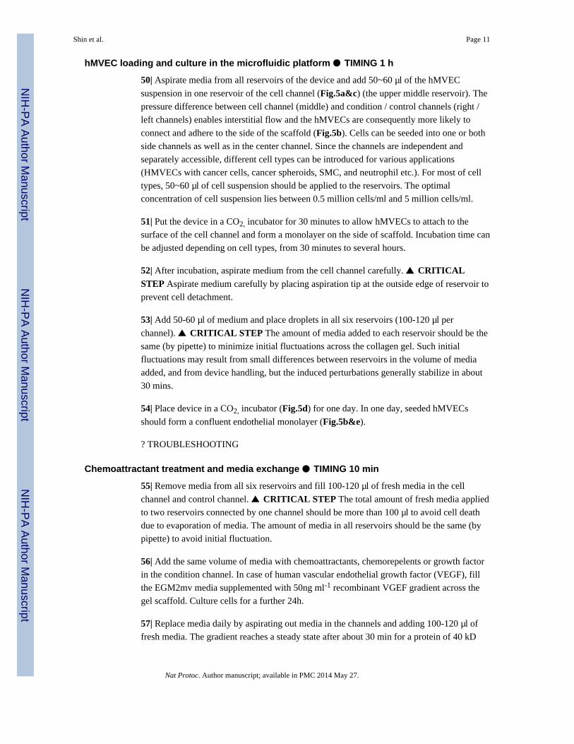
hMVEC loading and culture in the microfluidic platform ● TIMING 1 h
50| Aspirate media from all reservoirs of the device and add 50~60 μl of the hMVEC
suspension in one reservoir of the cell channel (Fig.5a&c) (the upper middle reservoir). The
pressure difference between cell channel (middle) and condition / control channels (right /
left channels) enables interstitial flow and the hMVECs are consequently more likely to
connect and adhere to the side of the scaffold (Fig.5b). Cells can be seeded into one or both
side channels as well as in the center channel. Since the channels are independent and
separately accessible, different cell types can be introduced for various applications
(HMVECs with cancer cells, cancer spheroids, SMC, and neutrophil etc.). For most of cell
types, 50~60 μl of cell suspension should be applied to the reservoirs. The optimal
concentration of cell suspension lies between 0.5 million cells/ml and 5 million cells/ml.
51| Put the device in a CO2, incubator for 30 minutes to allow hMVECs to attach to the
surface of the cell channel and form a monolayer on the side of scaffold. Incubation time can
be adjusted depending on cell types, from 30 minutes to several hours.
52| After incubation, aspirate medium from the cell channel carefully. ▲ CRITICALSTEP Aspirate medium carefully by placing aspiration tip at the outside edge of reservoir to
prevent cell detachment.
53| Add 50-60 μl of medium and place droplets in all six reservoirs (100-120 μl per
channel). ▲ CRITICAL STEP The amount of media added to each reservoir should be the
same (by pipette) to minimize initial fluctuations across the collagen gel. Such initial
fluctuations may result from small differences between reservoirs in the volume of media
added, and from device handling, but the induced perturbations generally stabilize in about
30 mins.
54| Place device in a CO2, incubator (Fig.5d) for one day. In one day, seeded hMVECs
should form a confluent endothelial monolayer (Fig.5b&e).
? TROUBLESHOOTING
Chemoattractant treatment and media exchange ● TIMING 10 min
55| Remove media from all six reservoirs and fill 100-120 μl of fresh media in the cell
channel and control channel. ▲ CRITICAL STEP The total amount of fresh media applied
to two reservoirs connected by one channel should be more than 100 μl to avoid cell death
due to evaporation of media. The amount of media in all reservoirs should be the same (by
pipette) to avoid initial fluctuation.
56| Add the same volume of media with chemoattractants, chemorepelents or growth factor
in the condition channel. In case of human vascular endothelial growth factor (VEGF), fill
the EGM2mv media supplemented with 50ng ml-1 recombinant VGEF gradient across the
gel scaffold. Culture cells for a further 24h.
57| Replace media daily by aspirating out media in the channels and adding 100-120 μl of
fresh media. The gradient reaches a steady state after about 30 min for a protein of 40 kD
Shin et al. Page 11
Nat Protoc. Author manuscript; available in PMC 2014 May 27.
NIH
-PA
Author M
anuscriptN
IH-P
A A
uthor Manuscript
NIH
-PA
Author M
anuscript

molecular weight (VEGF) but will dissipate over time if not replenished by either another
media change or by introducing a steady, slow flow through the channels by peristaltic or
syringe pump. Without slow perfusion, linearity can be maintained for 24 hours and easily
restored by daily replacement of media, which enables multiple experiments with the same
batch of cells. ▲ CRITICAL STEP The time to establish a gradient is determined by the
diffusion coefficient of the applied protein in the hydrogel, and can also be affected by
matrix binding. Slope can be visualized by a fluorescent molecule (e.g., dextran) and also
simulated by conventional CFD software (Fig.6). After applying a chemical gradient,
cellular responses can be monitored and quantified daily by conventional microscopy (Fig.6c&d). Media or cells in the channel can be collected for biochemical or PCR analysis.
Cell staining
58| At the desired cell culture endpoint, remove the remaining cell culture media in all
reservoirs by vacuum aspiration. ▲ CRITICAL STEP when aspirating media or other
solutions from the reservoirs, aspirate media carefully by placing aspiration tip at the outside
edge of reservoirs to prevent cells from detaching.
59| Rinse the channels of the device with PBS. Fill 90~100 μl PBS in one side of the
reservoirs, then let it flow along the channels and check to ensure that it also filled the
opposite reservoirs. Remove PBS in all reservoirs of the device. Repeat this step twice.
60| Add 50~60ul of 4% PFA in all reservoirs and leave it to stand for 15 min for cell
fixation. ! CAUTION Wear suitable protective clothing and gloves when working with 4%
PFA.
61| After 15 min of incubation, remove 4% PFA from each reservoir using a 1000 μl
pipette. ! CAUTION Properly dispose of the PFA.
62| Wash the channels twice with PBS as described in step (60). ! CAUTION The first wash
of PBS should be disposed into the PFA waste bottle.
63| Add 50~60ul of 0.1% Triton-X in each reservoir for solubilization and permeabilization
of cell membranes. Let incubate on bench top for 5min.
64| Aspirate 0.1% Trion-X and wash twice with PBS as in step (60).
█ PAUSE POINT The device filled with PBS can be stored for 1-2 days at 4° in the
refrigerator before fluorescent staining.
65| If fluorescent staining, follow option A. If using antibodies, follow option B. These
methods can be combined.
(A) Fluorescent staining ● TIMING 2 h
(i) Dilute Rhodamine Phalloidin in the ratio of 1:40 and DAPI in the ration of 1:1000 with
PBS to make a working concentration of fluorescent staining solution mixture. ▲
Shin et al. Page 12
Nat Protoc. Author manuscript; available in PMC 2014 May 27.
NIH
-PA
Author M
anuscriptN
IH-P
A A
uthor Manuscript
NIH
-PA
Author M
anuscript
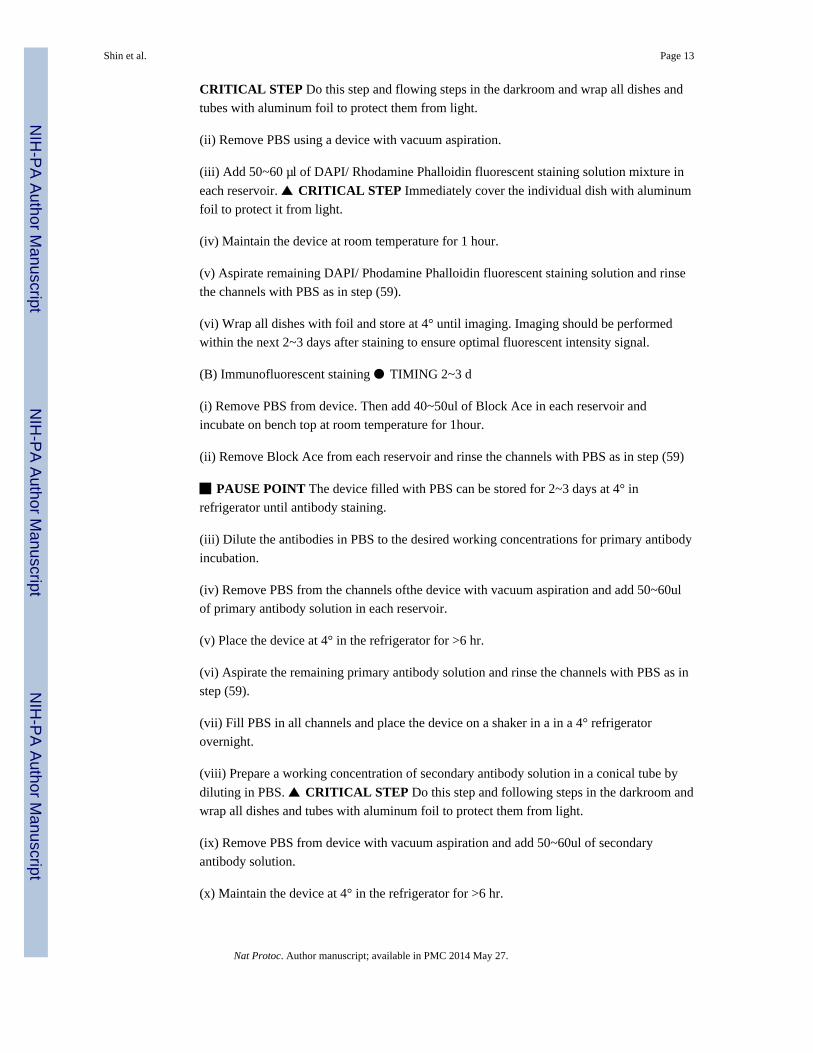
CRITICAL STEP Do this step and flowing steps in the darkroom and wrap all dishes and
tubes with aluminum foil to protect them from light.
(ii) Remove PBS using a device with vacuum aspiration.
(iii) Add 50~60 μl of DAPI/ Rhodamine Phalloidin fluorescent staining solution mixture in
each reservoir. ▲ CRITICAL STEP Immediately cover the individual dish with aluminum
foil to protect it from light.
(iv) Maintain the device at room temperature for 1 hour.
(v) Aspirate remaining DAPI/ Phodamine Phalloidin fluorescent staining solution and rinse
the channels with PBS as in step (59).
(vi) Wrap all dishes with foil and store at 4° until imaging. Imaging should be performed
within the next 2~3 days after staining to ensure optimal fluorescent intensity signal.
(B) Immunofluorescent staining ● TIMING 2~3 d
(i) Remove PBS from device. Then add 40~50ul of Block Ace in each reservoir and
incubate on bench top at room temperature for 1hour.
(ii) Remove Block Ace from each reservoir and rinse the channels with PBS as in step (59)
█ PAUSE POINT The device filled with PBS can be stored for 2~3 days at 4° in
refrigerator until antibody staining.
(iii) Dilute the antibodies in PBS to the desired working concentrations for primary antibody
incubation.
(iv) Remove PBS from the channels ofthe device with vacuum aspiration and add 50~60ul
of primary antibody solution in each reservoir.
(v) Place the device at 4° in the refrigerator for >6 hr.
(vi) Aspirate the remaining primary antibody solution and rinse the channels with PBS as in
step (59).
(vii) Fill PBS in all channels and place the device on a shaker in a in a 4° refrigerator
overnight.
(viii) Prepare a working concentration of secondary antibody solution in a conical tube by
diluting in PBS. ▲ CRITICAL STEP Do this step and following steps in the darkroom and
wrap all dishes and tubes with aluminum foil to protect them from light.
(ix) Remove PBS from device with vacuum aspiration and add 50~60ul of secondary
antibody solution.
(x) Maintain the device at 4° in the refrigerator for >6 hr.
Shin et al. Page 13
Nat Protoc. Author manuscript; available in PMC 2014 May 27.
NIH
-PA
Author M
anuscriptN
IH-P
A A
uthor Manuscript
NIH
-PA
Author M
anuscript
(xi) Aspirate remaining secondary antibody solution and rinse the channels with PBS as in
step (59).
(xii) Fill the channels of device with PBS and place on a shaker in a 4° refrigerator for
overnight then store device at 4° until imaging.
■ PAUSE POINT In this cell staining step, the incubating time with staining solution may
vary depending on the cell numbers and amount of cells in hydrogel. Working time should
be optimized.
●TIMING
Steps 1-8, Fabrication of the master: 3h
Steps 9-19, Fabrication of PDMS molds: 7 h
Steps 20-21, Cleaning glass coverslips: 5 h
Steps 22-26, Device assembly: 10 min
Steps 27-31, PDL coating of the microchannels: 5 h
Step 32, Surface hydrophobicity restoration: 1 day
Steps 33-39, Collagen gel solution preparation: 5 min
Steps 40-45, Collagen gel filling: 40 min
Steps 46-49, Cell suspension preparation: 10 min
Steps 50-54, hMVEC loading and culture in the microfluidic platform: 1 h
Steps 55-57, Chemoattractant treatment and media exchange: 10 min
Steps 58-64, Cell staining: 2h or 2~3 d
?TROUBLESHOOTING
Troubleshooting advice can be found in Table 2.
ANTICIPATED RESULTS
The described platform allows for a large number of different experimental cell culture
designs depending on which channels or gel regions contain cells, the types of cells used,
and the nature of biochemical gradients or flow that are imposed. We first focus on the
results obtained for the specific case described above, that of endothelial cells being seeded
in the center channel with no cells seeded elsewhere in the system (either the side channels
or the gel regions), and in the case with a gradient of growth factor applied on one side to
induce angiogenesis. Fig.7 shows successful culturing of hMVEC in the cell channel and a
3D sprouting angiogenic response in the direction of increased VEGF concentration (from
Shin et al. Page 14
Nat Protoc. Author manuscript; available in PMC 2014 May 27.
NIH
-PA
Author M
anuscriptN
IH-P
A A
uthor Manuscript
NIH
-PA
Author M
anuscript

right side). Cells can be observed to progressively invade 3D into the type 1 collagen
hydrogel towards the right side where a higher VEGF concentration has been introduced.
Sprouting of the endothelial monolayer is observed only on the right side of the center
channel, leaving the left side (no added VEGF) stable14. Using confocal microscopy, the
monolayer has been demonstrated to be confluent over the face of the gel and the 3D nature
of the capillaries has been confirmed. Other cell types exhibit a variety of responses when
seeded in the center channel and put in contact with a collagen hydrogel (Fig.8). Gradient of
growth factors or chemoattractants can regulate both the morphology and the degree of
cellular morphogenesis into the collagen hydrogel. Various experimental modes of cell
seeding and morphogenesis in hydrogel incorporating microfluidic assay are listed in Fig.9.
When hMVEC are seeded in the center channel and another cell type (e.g., cancer cells, 10T
1/2) is seeded and cultured in the side channel, paracrine interactions occur across the ~1
mm hydrogel region. Various responses can be observed. In some cases, cancer cells induce
a sprouting response in the endothelial monolayer, similar to that found with added VEGF8.
In other cases, the added cells migrate through the gel and interact with the other cells or
monolayer inducing cellular morphogenesis in some instances and in others suppressing it
(Fig.10a)14,15,21. The microfluidic cell culture assay also allows the study of 3D cell-cell
interactions and cell-ECM interactions26, especially for the evaluation of new synthesized
biodegradable polymers (hyaluronic acid, synthetic peptides, etc.) or other ECM materials
(Matrigel, fibrin etc.)29. Co-cultures of cancer cells-endothelial cells (Fig.10b&d)8,
hepatocyte-endothelial cells10, and smooth muscle cells (SMCs)-endothelial cells (Fig.10c)11 have already been realized, to enable study of cellular morphogenesis and
interactions. We proved that the assay can generate well-defined biochemical and
biophysical stimuli to multiple cell types interacting with each other, thereby replicating
many aspects of the in vivo microenvironment with significant implications for drug
discovery and artificial organ systems in vitro and with time and cost benefits for drug
screening.
Acknowledgments
We acknowledge support to S.C. from the National Research Foundation of Korea (Grant no. 2010-0023975), toR.S. from Japan Science and Technology Agency and Japan Society for Promotion of Science (22680037, G2212),and to R.D.K. from the National Science Foundation (CBET-0939511). We thank Dr. Yamato Kikkawa, TokyoUniv Pharm & Life Sci. for generously providing anti-CD146 antibody.
REFERENCES
1. Pampaloni F, Reynaud EG, Stelzer EHK. The third dimension bridges the gap between cell cultureand live tissue. Nature Reviews Molecular Cell Biology. 2007; 8:839–845.
2. Even-Ram S, Yamada KM. Cell migration in 3D matrix. Current opinion in cell biology. 2005;17:524–532. [PubMed: 16112853]
3. Feder-Mengus C, Ghosh S, Reschner A, Martin I, Spagnoli GC. New dimensions in tumorimmunology: what does 3D culture reveal? Trends in Molecular Medicine. 2008; 14:333–340.[PubMed: 18614399]
4. Griffith LG, Swartz MA. Capturing complex 3D tissue physiology in vitro. Nature ReviewsMolecular Cell Biology. 2006; 7:211–224.
5. Yamada KM, Cukierman E. Modeling tissue morphogenesis and cancer in 3D. Cell. 2007; 130:601–610. [PubMed: 17719539]
Shin et al. Page 15
Nat Protoc. Author manuscript; available in PMC 2014 May 27.
NIH
-PA
Author M
anuscriptN
IH-P
A A
uthor Manuscript
NIH
-PA
Author M
anuscript

6. Cukierman E, Pankov R, Yamada K. Cell interactions with three-dimensional matrices. Currentopinion in cell biology. 2002; 14:633–640. [PubMed: 12231360]
7. Wenger A, et al. Modulation of in vitro angiogenesis in a three-dimensional spheroidal coculturemodel for bone tissue engineering. Tissue Engineering. 2004; 10:1536–1547. [PubMed: 15588413]
8. Ghajar CM, Blevins KS, Hughes CCW, George SC, Putnam AJ. Mesenchymal stem cells enhanceangiogenesis in mechanically viable prevascularized tissues via early matrix metalloproteinaseupregulation. Tissue Engineering. 2006; 12:2875–2888. [PubMed: 17518656]
9. Chung S, Sudo R, Vickerman V, Zervantonakis I, Kamm R. Microfluidic Platforms for Studies ofAngiogenesis, Cell Migration, and Cell-Cell Interactions. Annals of Biomedical Engineering. 2010;38:1164–1177. [PubMed: 20336839]
10. Park JW, Vahidi B, Taylor AM, Rhee SW, Jeon NL. Microfluidic culture platform forneuroscience research. Nature protocols. 2006; 1:2128–2136.
11. Paguirigan AL, Beebe DJ. Protocol for the fabrication of enzymatically crosslinked gelatinmicrochannels for microfluidic cell culture. Nature protocols. 2007; 2:1782–1788.
12. Englert DL, Manson MD, Jayaraman A. Investigation of bacterial chemotaxis in flow-basedmicrofluidic devices. Nature protocols. 2010; 5:864–872.
13. Chung S, Sudo R, Zervantonakis I, Rimchala T, Kamm R. Surface Treatment Induced ThreeDimensional Capillary Morphogenesis in a Microfluidic Platform. Advanced Materials. 2009;21:4863–4867. [PubMed: 21049511]
14. Chung S, et al. Cell migration into scaffolds under co-culture conditions in a microfluidic platform.Lab on a Chip. 2009; 9:269–275. [PubMed: 19107284]
15. Sudo R, et al. Transport-mediated angiogenesis in 3D epithelial coculture. The FASEB Journal.2009; 23:2155–2164.
16. Vickerman V, Blundo J, Chung S, Kamm R. Design, fabrication and implementation of a novelmulti parameter control microfluidic platform for three-dimensional cell culture and real-timeimaging. Lab on a Chip. 2008; 8:1468–1477. [PubMed: 18818801]
17. Shin Y, et al. In vitro 3D collective sprouting angiogenesis under orchestrated ANG-1 and VEGFgradients. Lab Chip. 2011; 11:2175–2181. [PubMed: 21617793]
18. Jeong GS, S. H. Shin Y, Kwon GH, Kamm RD, Lee S-H, Chung S. Sprouting angiogenesis undera chemical gradient regulated by interaction with endothelial monolayer in microfluidic platform.Analytical Chemistry. 2011; 83:8454–8459. [PubMed: 21985643]
19. Wan C, Chung S, Kamm RD. Differentiation of Embryonic Stem Cells into Cardiomyocytes in aCompliant Microfluidic System. Annals of Biomedical Engineering. 2011; 39:1840–1847.[PubMed: 21336802]
20. Sudo R, et al. Transport-mediated angiogenesis in 3D epithelial coculture. The FASEB Journal.2009; 23:2155–2164.
21. Mack PJ, et al. Biomechanical regulation of endothelium-dependent events critical for adaptiveremodeling. Journal of Biological Chemistry. 2009; 284:8412–8420. [PubMed: 19047056]
22. Kothapalli CR, et al. A High-throughput Microfluidic Assay to Study Axonal Response to GrowthFactor Gradients. Lab on a Chip. 2011; 11:497–507. [PubMed: 21107471]
23. Zervantonakis IK, et al. Concentration gradients in microfluidic 3D matrix cell culture systems.International Journal of Micro-Nano Scale Transport. 2010; 1:27–36.
24. Amadi OC, et al. A low resistance microfluidic system for the creation of stable concentrationgradients in a defined 3D microenvironment. Biomedical Microdevices. 2010; 12:1027–1041.[PubMed: 20661647]
25. Jeon JS, Chung S, Kamm RD, Charest JL. Hot embossing for fabrication of a microfluidic 3D cellculture platform. Biomedical Microdevices. 2011; 13:325–333. [PubMed: 21113663]
26. Zervantonakis IK, Kothapalli CR, Chung S, Sudo R, Kamm RD. Microfluidic devices for studyingheterotypic cell-cell interactions and tissue specimen cultures under controlled microenvironments.Biomicrofluidics. 2011; 5:013406.
27. Qin D, Xia Y, Whitesides GM. Soft lithography for micro-and nanoscale patterning. Natureprotocols. 2010; 5:491–502.
Shin et al. Page 16
Nat Protoc. Author manuscript; available in PMC 2014 May 27.
NIH
-PA
Author M
anuscriptN
IH-P
A A
uthor Manuscript
NIH
-PA
Author M
anuscript

28. Han, S.; K. Y.; Shin, Y.; Kamm, RD.; Chung, S.; Cho, SW. Extracellular matrix mediated neuralstem cell differentiation in microenvironment. 2011. submitted
29. Jeong GS, et al. Microfluidic assay of endothelial cell migration in 3D interpenetrating polymersemi-network HA-Collagen hydrogel. Biomedical Microdevices. 2011; 13:717–723. [PubMed:21494794]
Shin et al. Page 17
Nat Protoc. Author manuscript; available in PMC 2014 May 27.
NIH
-PA
Author M
anuscriptN
IH-P
A A
uthor Manuscript
NIH
-PA
Author M
anuscript
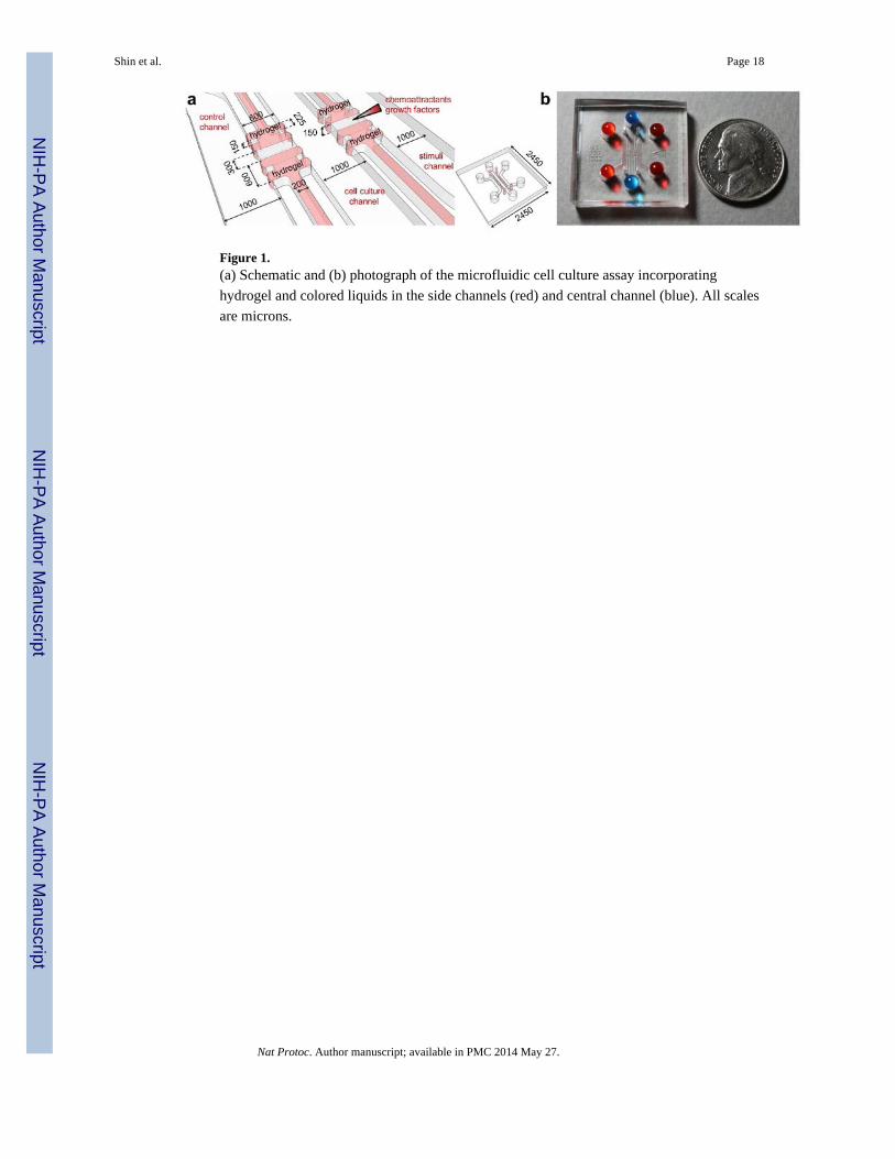
Figure 1.(a) Schematic and (b) photograph of the microfluidic cell culture assay incorporating
hydrogel and colored liquids in the side channels (red) and central channel (blue). All scales
are microns.
Shin et al. Page 18
Nat Protoc. Author manuscript; available in PMC 2014 May 27.
NIH
-PA
Author M
anuscriptN
IH-P
A A
uthor Manuscript
NIH
-PA
Author M
anuscript
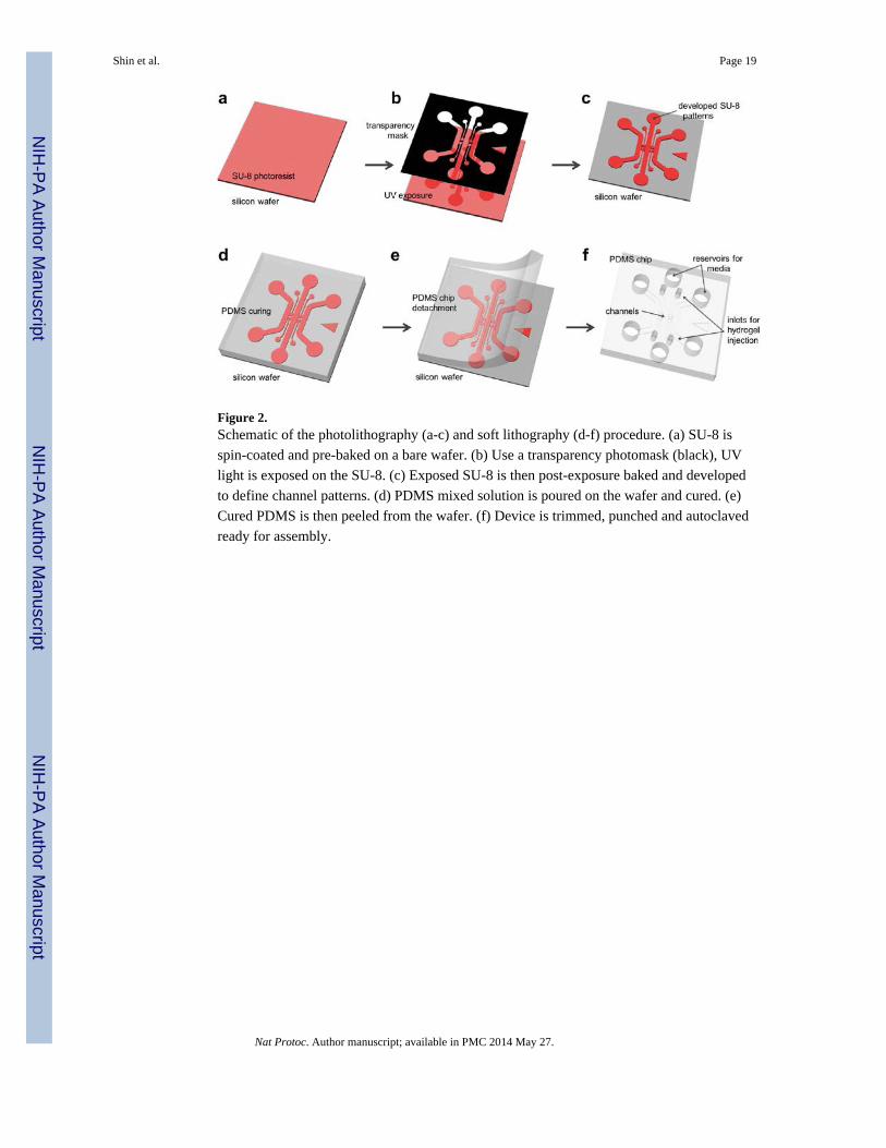
Figure 2.Schematic of the photolithography (a-c) and soft lithography (d-f) procedure. (a) SU-8 is
spin-coated and pre-baked on a bare wafer. (b) Use a transparency photomask (black), UV
light is exposed on the SU-8. (c) Exposed SU-8 is then post-exposure baked and developed
to define channel patterns. (d) PDMS mixed solution is poured on the wafer and cured. (e)
Cured PDMS is then peeled from the wafer. (f) Device is trimmed, punched and autoclaved
ready for assembly.
Shin et al. Page 19
Nat Protoc. Author manuscript; available in PMC 2014 May 27.
NIH
-PA
Author M
anuscriptN
IH-P
A A
uthor Manuscript
NIH
-PA
Author M
anuscript
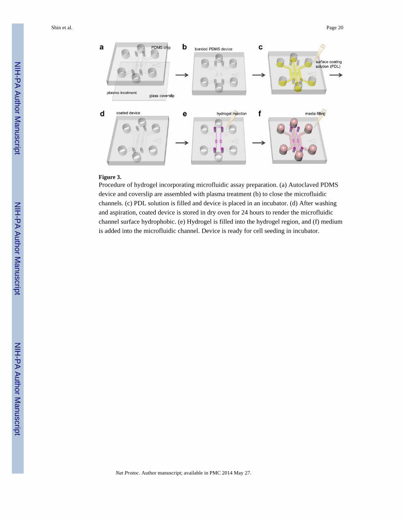
Figure 3.Procedure of hydrogel incorporating microfluidic assay preparation. (a) Autoclaved PDMS
device and coverslip are assembled with plasma treatment (b) to close the microfluidic
channels. (c) PDL solution is filled and device is placed in an incubator. (d) After washing
and aspiration, coated device is stored in dry oven for 24 hours to render the microfluidic
channel surface hydrophobic. (e) Hydrogel is filled into the hydrogel region, and (f) medium
is added into the microfluidic channel. Device is ready for cell seeding in incubator.
Shin et al. Page 20
Nat Protoc. Author manuscript; available in PMC 2014 May 27.
NIH
-PA
Author M
anuscriptN
IH-P
A A
uthor Manuscript
NIH
-PA
Author M
anuscript

Figure 4.(a) Color of type 1 collagen solution (before gellation) with different pH; about 5.0 (left),
7.4 (center) and 11.0 (right). The prepared type 1 collagen solution was then filled into the
hydrogel region. (b) SEM image of gelled filbers of type 1 collagen gel (after gellation) with
different initial pH; about 5.0 (left), 7.4 (center) and 11.0 (right). Scale bars indicate 1
microns. (c) In hydrogel filling, use 10 ul pipette and slowly inject hydrogel into the gel
region. (d) Injected hydrogel perfectly filled into the hydrogel region (red) and stoped by
surface tension between post and PDMS wall.
Shin et al. Page 21
Nat Protoc. Author manuscript; available in PMC 2014 May 27.
NIH
-PA
Author M
anuscriptN
IH-P
A A
uthor Manuscript
NIH
-PA
Author M
anuscript

Figure 5.Cell culture in microfluidic assay. (a) After aspiration of medium in the reservoir, 50~60 μl
of the hMVEC suspension is added into one reservoir connected to the center channel. (b)
Hydrostatic pressure difference in the reservoirs pushes the suspended hMVECs onto the
collagen gel to facilitate attachment. hMVECs right after seeding (right top) and tight
monolayer at 1 day (right bottom). Scale bar indicates 250 microns. (c) To add cell
suspension or media into the reservoir, use a pipette and gently inject medium into one
reservoir after aspiration. The filled liquid automatically fills the channel and replaces the
contained medium. (d) Cell seeded assays can be stored in incubator or 6 well plate with
various experimental conditions. (e) In 4 days of culture, hMVECs form intact monolayer in
channel and on type 1 collagen wall. Actin filaments and nuclei were then stained with
rhodamine-phalloidin (yellow; Sigma-Aldrich) and 4',6-diamidino-2-phenylindole (DAPI;
blue; Sigma-Aldrich), respectively. Scale bar indicates 50 microns. EC monolayer was
imaged by confocal microscope13 and its diffusion coefficient was measured by fluorescent
dextran diffusion13,14,18.
Shin et al. Page 22
Nat Protoc. Author manuscript; available in PMC 2014 May 27.
NIH
-PA
Author M
anuscriptN
IH-P
A A
uthor Manuscript
NIH
-PA
Author M
anuscript
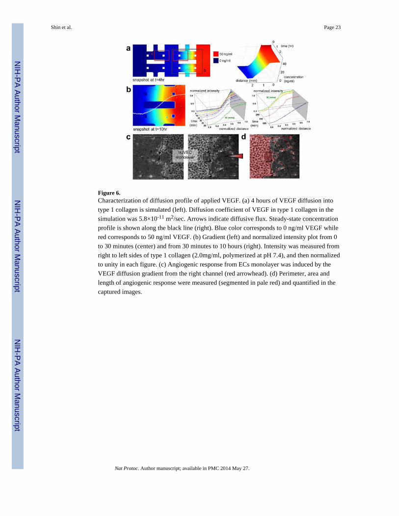
Figure 6.Characterization of diffusion profile of applied VEGF. (a) 4 hours of VEGF diffusion into
type 1 collagen is simulated (left). Diffusion coefficient of VEGF in type 1 collagen in the
simulation was 5.8×10⁻¹¹ m2/sec. Arrows indicate diffusive flux. Steady-state concentration
profile is shown along the black line (right). Blue color corresponds to 0 ng/ml VEGF while
red corresponds to 50 ng/ml VEGF. (b) Gradient (left) and normalized intensity plot from 0
to 30 minutes (center) and from 30 minutes to 10 hours (right). Intensity was measured from
right to left sides of type 1 collagen (2.0mg/ml, polymerized at pH 7.4), and then normalized
to unity in each figure. (c) Angiogenic response from ECs monolayer was induced by the
VEGF diffusion gradient from the right channel (red arrowhead). (d) Perimeter, area and
length of angiogenic response were measured (segmented in pale red) and quantified in the
captured images.
Shin et al. Page 23
Nat Protoc. Author manuscript; available in PMC 2014 May 27.
NIH
-PA
Author M
anuscriptN
IH-P
A A
uthor Manuscript
NIH
-PA
Author M
anuscript

Figure 7.Confocal image of 3D angiogenic response into the type 1 collagen (2.0 mg/ml, polymerized
at pH 7.4) induced by VEGF diffused from the right channel. (left) 3D projection image of
the capillary-like structures formed by hMVEC on day 12 of culture, which was
reconstructed from confocal z-stack images. hMVECs formed 3D capillary-like networks
extending into the collagen gel, which were stained with CD-146 (hMVEC, red) and DAPI
(nucleus, blue). (right) A single z-plane image and x-z and y-z cross-sectional images of the
capillary-like networks. Image field corresponds to the left image. Arrowheads indicate a
capillary-like structure which is continuous from the monolayer in the channel. An arrow in
the x-z image indicates a lumen of the capillary-like structure.
Shin et al. Page 24
Nat Protoc. Author manuscript; available in PMC 2014 May 27.
NIH
-PA
Author M
anuscriptN
IH-P
A A
uthor Manuscript
NIH
-PA
Author M
anuscript

Figure 8.3D interaction of various types of cells with incorporated hydrogel. (a) Cells are seeded onto
hydrogel, and then migrate in individually. (top) Migration of mouse smooth muscle
precursor cells (10T 1/2) into type 1 collagen (2.0 mg/ml, initial pH 9.0), on day 6 co-
cultured with hMVECs (right channel). (center) Sheet like migration of mouse breast cancer
cells (MTLn3) into type 1 collagen (2.0 mg/ml, initial pH 7.4) in day 3 co-cultured with
hMVECs (right channel). (bottom) Migration of human breast cancer cells (MDA-MB-231)
into type 1 collagen (2.0 mg/ml, initial pH 7.4) on day 3 under 5 % FBS gradient. (b) Cells
formed 3D tissue-like structures on hydrogel. (top) Axonal growth into type 1 collagen (1.0
mg/ml, initial pH 7.4) from primary mouse cortical neurons cultured 2 days under 50 μM
Forskolin gradient. (center) Primary hepatocyte cultured on type 1 collagen (2.0 mg/ml,
initial pH 7.4) in 7 days under interstitial flow condition. Cells were fixed at day 7 and
stained for actin filaments (rhodamine-phalloidin; red), nuclei (DAPI; blue) and SEC
fraction (GFP; green). Tight tissue-like hepatocyte structure can be found, without
migration. (bottom) Human breast cancer cells (MCF-7) cultured on type 1 collagen (2.0
mg/ml, initial pH 9.0) for 3 days under 5 % FBS gradient formed tight tumor colony without
migration. (c) Endothelial cells form intact monolayer on hydrogel, showing capillary
morphogenesis into hydrogel. hMVEC cells form complex capillary structure in type 1
collagen (2.0 mg/ml, initial pH 7.4) for 5 days under VEGF gradient and ANG-1
supplement. (d) Floating cells in the media migrate into hydrogel under chemoattractant
gradient. T lymphocyte cells (Jurkat) migrating into type 1 collagen (2.0 mg/ml, initial pH
7.4) on day 3 under SDF-1 gradient. (e) Co-culture of neutrophil (HL60) in microfluidic
channel covered by hMVEC monolayer cultured 3 days. HL60 migrated through the
nMVEC monolayer and then into type 1 collagen (2.0 mg/ml, initial pH 10). Cells were
fixed at day 4 and stained for actin filaments (rhodaminephalloidin; red), nuclei (DAPI;
blue) and neutrophil (CFDA-SE cell tracker; green). In all other figures not mentioned, actin
filaments and nuclei were stained with rhodamine-phalloidin (yellow) and DAPI (blue),
respectively. White lines indicate outline of incorporated hydrogel. Scale bars indicate 100
μm.
Shin et al. Page 25
Nat Protoc. Author manuscript; available in PMC 2014 May 27.
NIH
-PA
Author M
anuscriptN
IH-P
A A
uthor Manuscript
NIH
-PA
Author M
anuscript
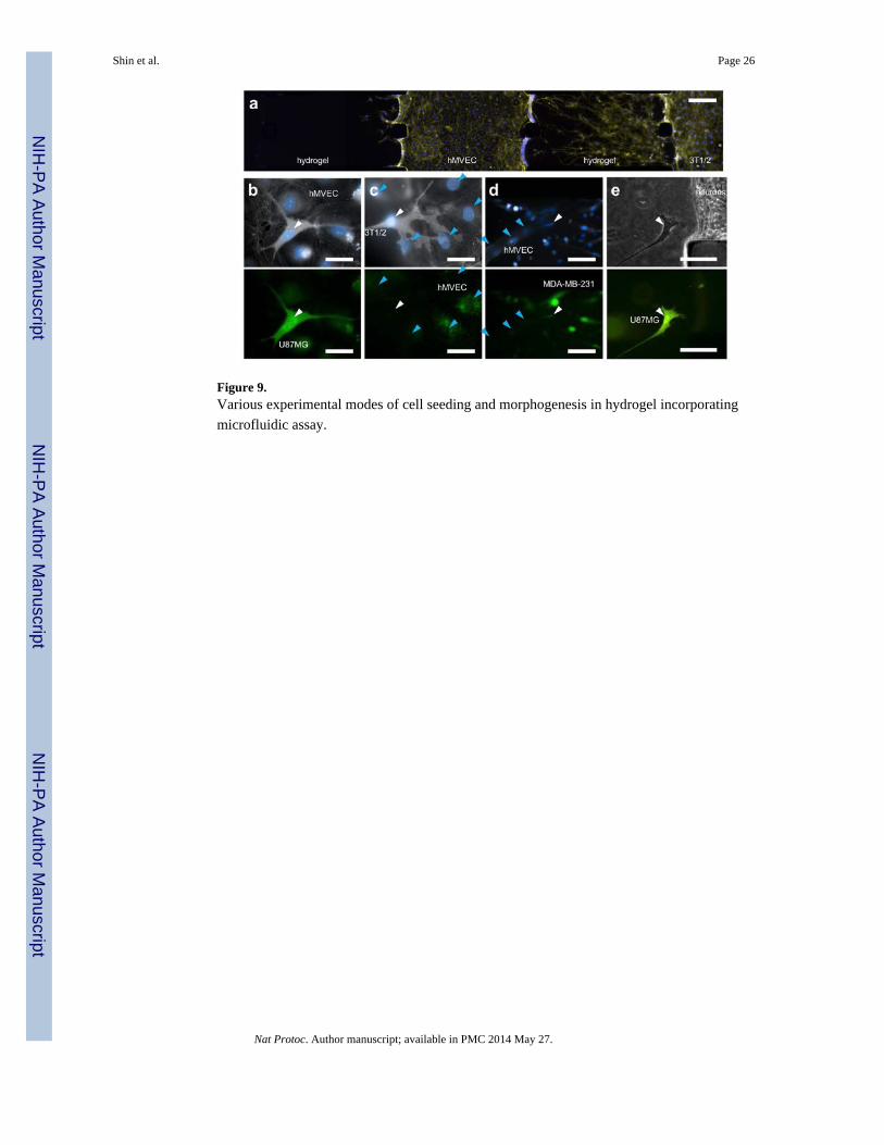
Figure 9.Various experimental modes of cell seeding and morphogenesis in hydrogel incorporating
microfluidic assay.
Shin et al. Page 26
Nat Protoc. Author manuscript; available in PMC 2014 May 27.
NIH
-PA
Author M
anuscriptN
IH-P
A A
uthor Manuscript
NIH
-PA
Author M
anuscript

Figure 10.Examples of cell-cell 3D interaction in hydrogel. (a) Co-culture of SMCs (10T 1/2; right
channel) and ECs (hMVEC; center channel). Active 3D sprouting angiogenesis into type 1
collagen is monitored (into left hydrogels), while the hMVEC monolayer is stabilized by the
presence of SMCs (right hydrogels). 10T 1/2 migration was also activated by the existence
of hMVEC monolayer in the center channel. Actin filaments and nuclei were stained with
rhodamine-phalloidin (yellow) and DAPI (blue), respectively. (b) GFP transfected U87MG
(white arrowheads) transmigrated through the hMVEC monolayer. Colors indicate actin
(white), nucleus (blue) and GFP (green). Scale bars 50 μm. (c) Interaction between SMC
(white arrowhead) and hMVEC (blue arrowheads). A SMC touches the hMVEC monolayer
with its filopodia, and becomes adhered to the monolayer. Colors indicate actin (white),
nucleus (blue) and EC-specific primary antibody (green). Scale bars 50 μm. (d) GFP
transfected breast cancer cell MDA-MB-231 (white arrowhead) interacting with hMVEC
(blue arrowheads) sprouts in type 1 collagen scaffold. Colors indicate actin (white), nucleus
(blue) and GFP (green). Scale bars 100 μm. (e) Primary neurons generating axons towards
GFP transfected glioblastoma cells U87MG (white arrowheads). Colors indicate actin
(white), nucleus (blue) and GFP (green). Scale bars 100 μm.
Shin et al. Page 27
Nat Protoc. Author manuscript; available in PMC 2014 May 27.
NIH
-PA
Author M
anuscriptN
IH-P
A A
uthor Manuscript
NIH
-PA
Author M
anuscript

NIH
-PA
Author M
anuscriptN
IH-P
A A
uthor Manuscript
NIH
-PA
Author M
anuscript
Shin et al. Page 28
Table 1
Examples of surface coating solution and preferred cell types in hydrogel incorporating microfluidic assay.
Surface type Preferred cell types toculture on cell cultureplate
Preferred cell types to culturein hydrogel incorporatingmicrofluidic assay
Purpose of experiment
Without coating - Neuronal cells, hepatocytes inFig.8bStem cellsFloating cells (Jurkat in Fig.8d)
To culture cells only on the hydrogel surfaceTo culture cells embedded in hydrogelTo make cells only interact with hydrogelsurface
Type 1 collagen Endothelial cells,hepatocytes, fibroblasts,tumor cells, neuronal cells
Tumor cells
Poly-Lysine (PDL, PLL) Neuronal cells, tumor cells Endothelial cells in Fig.8c, Fig.8eTumor cells in Fig.8a, Fig.8b
To generate 3D capillary morphogenesis intotype 1 collagenTo generate 3D migration into type 1 collagen*Enhanced adhesion to type 1 collagenhydrogel
Fibronectin, laminin Neuronal cells, tumor cells *Weak adhesion to type 1 collagen hydrogel
Matrigel Endothelial cells Endothelial cells To mimic basement membrane
Nat Protoc. Author manuscript; available in PMC 2014 May 27.

NIH
-PA
Author M
anuscriptN
IH-P
A A
uthor Manuscript
NIH
-PA
Author M
anuscript
Shin et al. Page 29
Table 2
Troubleshooting table.
Step Problem Possible reason Solution
26 Defect in bonding Mishandling in bonding process Press the defective region using a pair of tweezers until theunbounded PDMS surface adheres to the glass surface.
Weak bonding Weak plasma treatment Increase plasma treatment time or place the bonded deviceat 80 °C in an oven for several hours.
41 Collagen solution flows outinto the media channel
Hydrophobicity of the device not yetrecovered to the required level
Let device dry for a longer time (e.g. 48 hrs after PDLcoating) in an 80 °C oven.
54 Non-confluent endothelialmonolayer on one day
Low hMVECs seeding density Wait one more day and increase cell seeding density.
Unhealthy hMVECs Poor surface coating Use fresh surface coating solution.
Media evaporation in reservoirs Maintain a stable humidity in the incubator and add moremedium into the reservoirs.
Nat Protoc. Author manuscript; available in PMC 2014 May 27.


![HPV detection methods · At present the only real-time assay that allows con-sensus HPV-PCR with simultaneous typing is a molec-ular beacons assay [37]. However, the multiplicity](https://img.pdfslide.us/doc/110x75/60a217a3a81c97703d422379/hpv-detection-methods-at-present-the-only-real-time-assay-that-allows-con-sensus.jpg)